CN211437577U - Stamping die for large negative angle bending forming - Google Patents
Stamping die for large negative angle bending forming Download PDFInfo
- Publication number
- CN211437577U CN211437577U CN201920966524.4U CN201920966524U CN211437577U CN 211437577 U CN211437577 U CN 211437577U CN 201920966524 U CN201920966524 U CN 201920966524U CN 211437577 U CN211437577 U CN 211437577U
- Authority
- CN
- China
- Prior art keywords
- die
- bending
- punch
- negative angle
- plate
- Prior art date
- Legal status (The legal status is an assumption and is not a legal conclusion. Google has not performed a legal analysis and makes no representation as to the accuracy of the status listed.)
- Active
Links
Images


Abstract
The utility model provides a stamping die for large negative angle bending forming, which comprises an upper die and a lower die which are correspondingly arranged, wherein the upper die comprises an upper die base, an upper padding plate and a punch assembly, the upper padding plate is fixedly arranged at the bottom of the upper die base, the punch assembly is arranged at the bottom of the upper padding plate, the punch assembly comprises a roller fixing base, a roller and a bending punch, the roller fixing base is fixedly arranged at the bottom of the upper padding plate, and the bending punch is hinged with the roller fixing base through the roller; the bottom surface of the bending punch is a first plane part used for pressing the material sheet, and the side surface of the bending punch is a second plane part connected with the first plane part; the utility model discloses a department sets up the drift of bending with it articulated at the upper die base, and the drift of bending under the natural state is because self action of gravity is in flagging state, and the width of drift is less than the groove width of waiting to process the work piece to the realization is bent the drift and is not interfered with the work piece, the machining precision of very high product at compound die and drawing of patterns in-process.
Description
Technical Field
The utility model relates to a stamping die technical field, in particular to be used for fashioned stamping die of bending of big negative angle.
Background
Stamping die is also called stamping die, hardware die and hardware stamping die. The method is a pressure processing method for obtaining parts with certain size requirement and qualified appearance quality by applying certain pressure on a metal or nonmetal plate by using a die fixed on a punch press or a pressing machine to separate or form the material.
With the development of science and technology and the progress of society, the application of stamping dies is more and more extensive, and especially in the automobile industry, its style and structure are constantly being updated and changed, therefore the variety of automobile parts is very much. Because the precision requirement of the automobile industry on parts is particularly high, when the automobile parts are manufactured, the machining efficiency needs to be ensured, and meanwhile, the quality of parts needs to be ensured.
When a groove-shaped workpiece with a back-off structure is machined in the prior art, because the space in a workpiece groove is narrow, a forming punch is difficult to be separated from the groove when a large negative angle is bent, and when the stamping die in the prior art is used for machining such products, the punch is directly taken out from the groove, so that the back-off part at the upper end of the workpiece is easy to deform, and the precision of the product cannot meet the requirement.
Improvements are therefore needed.
SUMMERY OF THE UTILITY MODEL
An object of the utility model is to provide an easy drawing of patterns, machining precision are high, be used for big negative angle fashioned stamping die of bending to solve above-mentioned problem.
The utility model discloses a following technical scheme realizes above-mentioned purpose:
a stamping die for large negative angle bending forming comprises an upper die and a lower die which are correspondingly arranged, wherein the upper die comprises an upper die base, an upper base plate and a punch assembly, the upper base plate is fixedly arranged at the bottom of the upper die base, the punch assembly is arranged at the bottom of the upper base plate, the punch assembly comprises a roller fixing seat, a roller and a bending punch, the roller fixing seat is fixedly arranged at the bottom of the upper base plate, and the bending punch is hinged with the roller fixing seat through the roller; the bottom surface of the bending punch is a first plane part used for pressing a material sheet, and the side surface of the bending punch is a second plane part connected with the first plane part; the lower die comprises a lower die base, a lower backing plate and a buoyancy lifting assembly, the lower backing plate is fixedly arranged at the upper part of the lower die, a female die is arranged on the lower backing plate, a bending template for bending material sheets is arranged on the side surface of the female die, and the buoyancy lifting assembly is arranged in the female die; the buoyancy lifting assembly comprises a buoyancy lifting plate connected with the lower die base through a guide post, and the bottom of the buoyancy lifting plate is also provided with a nitrogen spring in contact with the buoyancy lifting plate.
In a further technical scheme, two bending punch heads are arranged and are hinged with the roller fixing seat through the rollers in a bilateral symmetry mode.
In a further technical scheme, the bottom of the upper backing plate is provided with a limiting groove, and the upper part of the bending punch is provided with a limiting pin extending into the limiting groove.
In a further technical scheme, the upper part of the lower base plate is provided with two positioning thimbles for limiting the position of the material sheet, and the two positioning thimbles are respectively positioned on two sides of the female die.
In a further technical scheme, a reset spring which is correspondingly arranged with the positioning thimble is arranged in the lower cushion plate, and the reset spring is connected with the bottom of the positioning thimble.
In a further technical scheme, the upper part of the upper die base is provided with upper die feet, and the lower part of the lower die base is provided with lower die feet.
In a further technical scheme, an included angle between the first plane part and the second plane part is smaller than 90 degrees.
The beneficial effects of the utility model reside in that: the utility model discloses a department sets up the drift of bending with it articulated at the upper die base, and the drift of bending under the natural state is because self action of gravity is in flagging state, and the width of drift is less than the groove width of waiting to process the work piece to the realization is bent the drift and is not interfered with the work piece, the machining precision of very high product at compound die and drawing of patterns in-process.
Drawings
In fig. 1, a is a schematic structural diagram of a product before bending processing, and b is a schematic structural diagram of the product after bending processing;
fig. 2 is a schematic view of the overall structure of the present invention;
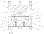
FIG. 3 is an enlarged schematic view of portion A of FIG. 2;
FIG. 4 is a schematic structural diagram of a bending die in a clamping state;
FIG. 5 is a schematic view of the mechanism of the open state of the bending mold.
Detailed Description
The present invention will be further explained with reference to the accompanying drawings:
as shown in fig. 1 to 4, a stamping die for large negative angle bending forming includes an upper die 1 and a lower die 2 which are correspondingly arranged, where the upper die 1 includes an upper die holder 11, an upper padding plate 12 and a punch assembly 3, the upper padding plate 12 is fixedly arranged at the bottom of the upper die holder 11, the punch assembly 3 is mounted at the bottom of the upper padding plate 12, the punch assembly 3 includes a roller fixing seat 31, a roller 32 and a bending punch 33, the roller fixing seat 31 is fixedly arranged at the bottom of the upper padding plate 12, and the bending punch 33 is hinged to the roller fixing seat 31 through the roller; the bottom surface of the bending punch 33 is a first flat surface part 33a used for pressing a material sheet, the side surface of the bending punch 33 is arranged to be a second flat surface part 33b connected with the first flat surface part 33a, and an included angle alpha between the first flat surface part 33a and the second flat surface part 33b is smaller than 90 degrees; the lower die 2 comprises a lower die base 21, a lower cushion plate 22 and a buoyancy lifting assembly 4, the lower cushion plate 22 is fixedly arranged at the upper part of the lower die 2, a female die 22a is arranged on the lower cushion plate 22, a bending template 5 for bending a material sheet 6 is arranged on the side surface of the female die 22a, and the buoyancy lifting assembly 4 is arranged in the female die 22 a; the buoyancy lifting assembly 4 comprises a buoyancy lifting plate 41 connected with the lower die base 21 through a guide post, and a nitrogen spring 42 in contact with the buoyancy lifting plate 41 is further arranged at the bottom of the buoyancy lifting plate 41.
In this embodiment, two bending punches 33 are provided, and are hinged to the roller holders 31 through the rollers, respectively, in a bilaterally symmetrical manner.
In this embodiment, the bottom of the upper cushion plate 12 is provided with a limiting groove 12a, and the upper portion of the bending punch 33 is provided with a limiting pin 33c extending into the limiting groove 12 a.
In this embodiment, the upper portion of the lower cushion plate 22 is provided with two positioning pins 22b for defining the material sheet position, and the two positioning pins 22b are respectively located at two sides of the concave die 22 a.
In this embodiment, the lower pad 22 has a return spring 22c disposed therein corresponding to the positioning pin 22b, and the return spring 22c is connected to the bottom of the positioning pin 22 b.
In this embodiment, the upper die base 11 is provided with an upper die leg 11a at an upper portion thereof, and the lower die base 21 is provided with a lower die leg 21a at a lower portion thereof.
The working principle is as follows: before processing, operating personnel will treat the sheet metal component of processing and place the upper portion at buoyancy lift plate 41, because the effect of gravity, drift subassembly 3 this moment all is in the state of natural flagging, and after the sheet metal component placed and finishes, the whole vertical downstream of punch press drive upper die base 11, until drift subassembly 3 and sheet metal component contact, the state of mould this moment is as shown in fig. 2.
After the punch assembly 3 contacts with the sheet metal part, the punch press continues to drive the punch assembly 3 to vertically move downwards, due to the obstruction of the sheet metal part, the bending punch 33 rotates around the rolling shaft until the first plane part 33a of the bending punch 33 is completely attached to the surface of the sheet metal part, the punch press continues to move downwards and compresses the nitrogen spring 42, the bending template 5 is matched with the second plane of the bending punch 33 at the moment, the edge of the sheet metal part is bent until the nitrogen spring 42 is completely compressed, and the state of the die is as shown in fig. 3 at the moment.
After bending is finished, the punching machine drives the whole upper die holder 11 to vertically move upwards until the bending punch 33 is separated from the sheet metal part and returns to a naturally drooping state under the action of gravity, and meanwhile, the nitrogen spring 42 ejects the floating plate 41 out of the female die 22a and ejects the sheet metal part out of the female die 22a, and at the moment, the die state is as shown in fig. 4.
The foregoing illustrates and describes the principles, general features, and advantages of the present invention. It will be understood by those skilled in the art that the present invention is not limited to the above embodiments, and that the foregoing embodiments and descriptions are provided only to illustrate the principles of the present invention without departing from the spirit and scope of the present invention. The scope of the invention is defined by the appended claims and equivalents thereof.
Claims (7)
1. The utility model provides a stamping die for big negative angle is bent fashioned, includes the last mould and the lower mould that correspond the setting, its characterized in that: the upper die comprises an upper die base, an upper padding plate and a punch assembly, the upper padding plate is fixedly arranged at the bottom of the upper die base, the punch assembly is installed at the bottom of the upper padding plate, the punch assembly comprises a roller fixing seat, a roller and a bending punch, the roller fixing seat is fixedly arranged at the bottom of the upper padding plate, and the bending punch is hinged with the roller fixing seat through the roller; the bottom surface of the bending punch is a first plane part used for pressing a material sheet, and the side surface of the bending punch is a second plane part connected with the first plane part; the lower die comprises a lower die base, a lower backing plate and a buoyancy lifting assembly, the lower backing plate is fixedly arranged at the upper part of the lower die, a female die is arranged on the lower backing plate, a bending template for bending material sheets is arranged on the side surface of the female die, and the buoyancy lifting assembly is arranged in the female die; the buoyancy lifting assembly comprises a buoyancy lifting plate connected with the lower die base through a guide post, and the bottom of the buoyancy lifting plate is also provided with a nitrogen spring in contact with the buoyancy lifting plate.
2. The stamping die for large negative angle bending forming according to claim 1, wherein: the number of the bending punch heads is two, and the bending punch heads are hinged to the roller fixing seats through the rollers in a bilateral symmetry mode.
3. The stamping die for large negative angle bending forming according to claim 1 or 2, wherein: the bottom of the upper backing plate is provided with a limiting groove, and the upper part of the bending punch is provided with a limiting pin extending into the limiting groove.
4. The stamping die for large negative angle bending forming according to claim 3, wherein: and the upper part of the lower base plate is provided with two positioning thimbles for limiting the position of the material sheet, and the two positioning thimbles are respectively positioned at two sides of the female die.
5. The stamping die for large negative angle bending forming according to claim 4, wherein: the lower backing plate is internally provided with a return spring which is correspondingly arranged with the positioning thimble, and the return spring is connected with the bottom of the positioning thimble.
6. The stamping die for large negative angle bending forming according to claim 1, wherein: the upper die base is provided with upper die legs at the upper part, and the lower die base is provided with lower die legs at the lower part.
7. The stamping die for large negative angle bending forming according to claim 1, wherein: the included angle between the first plane part and the second plane part is smaller than 90 degrees.
Priority Applications (1)
| Application Number | Priority Date | Filing Date | Title |
|---|---|---|---|
| CN201920966524.4U CN211437577U (en) | 2019-06-26 | 2019-06-26 | Stamping die for large negative angle bending forming |
Applications Claiming Priority (1)
| Application Number | Priority Date | Filing Date | Title |
|---|---|---|---|
| CN201920966524.4U CN211437577U (en) | 2019-06-26 | 2019-06-26 | Stamping die for large negative angle bending forming |
Publications (1)
| Publication Number | Publication Date |
|---|---|
| CN211437577U true CN211437577U (en) | 2020-09-08 |
Family
ID=72319355
Family Applications (1)
| Application Number | Title | Priority Date | Filing Date |
|---|---|---|---|
| CN201920966524.4U Active CN211437577U (en) | 2019-06-26 | 2019-06-26 | Stamping die for large negative angle bending forming |
Country Status (1)
| Country | Link |
|---|---|
| CN (1) | CN211437577U (en) |
Cited By (1)
| Publication number | Priority date | Publication date | Assignee | Title |
|---|---|---|---|---|
| CN110479804A (en) * | 2019-06-26 | 2019-11-22 | 广东天倬智能装备科技有限公司 | A kind of stamping die for big negative angle bending and molding |
-
2019
- 2019-06-26 CN CN201920966524.4U patent/CN211437577U/en active Active
Cited By (1)
| Publication number | Priority date | Publication date | Assignee | Title |
|---|---|---|---|---|
| CN110479804A (en) * | 2019-06-26 | 2019-11-22 | 广东天倬智能装备科技有限公司 | A kind of stamping die for big negative angle bending and molding |
Similar Documents
| Publication | Publication Date | Title |
|---|---|---|
| CN202779384U (en) | Punching die with convex dies capable of moving horizontally | |
| CN202087692U (en) | Die for the negative angel bending of sheet metal | |
| CN102303074A (en) | Side hole punching die | |
| CN108393397B (en) | Continuous stamping die for automobile corner plate pieces | |
| CN205289438U (en) | Edge rolling mould | |
| CN110919378B (en) | Panel beating all-in-one of polishing of buckling | |
| CN211437577U (en) | Stamping die for large negative angle bending forming | |
| CN110479804A (en) | A kind of stamping die for big negative angle bending and molding | |
| CN211437767U (en) | Punching and trimming forming die for two ends of inner reinforcing plate of automobile front wheel | |
| CN201871614U (en) | Automobile shock absorber connecting plate shaping die | |
| CN201799525U (en) | Die with tapered wedge | |
| CN204564822U (en) | Bender reflexed pressuring flat device | |
| CN207533817U (en) | A kind of guide and locating mechanism of punching press progressive die | |
| CN201720294U (en) | Hypoid bending mechanism | |
| CN206747410U (en) | A kind of carved punched part flanging die of V-arrangement | |
| CN107030197B (en) | A kind of integrally formed mold of multiple flanging | |
| CN210676451U (en) | Composite bending die capable of reducing work stations | |
| CN214688793U (en) | Fixing device is used in coining mill production and processing | |
| CN2693370Y (en) | Second compacting invert punching die for refrigerator beam | |
| CN108356147B (en) | Continuous stamping die for automobile seat slide rail material sheets | |
| CN209424401U (en) | Integrated steel ring expanding press-moulding die | |
| CN202343678U (en) | Tool for forming U-shaped clips of steel plate spring | |
| CN210586711U (en) | Multi-bending one-step forming stamping die | |
| CN213728787U (en) | Stretching forming device for sheet special-shaped parts | |
| CN220426548U (en) | Composite die for one-step forming of bending and flanging |
Legal Events
| Date | Code | Title | Description |
|---|---|---|---|
| GR01 | Patent grant | ||
| GR01 | Patent grant | ||
| CP02 | Change in the address of a patent holder | ||
| CP02 | Change in the address of a patent holder |
Address after: 523000 Building 1, No. 90 Chongde Road, Hengli Town, Dongguan City, Guangdong Province Patentee after: GUANGDONG TIANZHUO INTELLIGENT EQUIPMENT TECHNOLOGY Co.,Ltd. Address before: 523000 peach garden high tech Industrial Park, Hengli Town, Dongguan, Guangdong Patentee before: GUANGDONG TIANZHUO INTELLIGENT EQUIPMENT TECHNOLOGY Co.,Ltd. |