EP2407073B1 - Staubsauger - Google Patents
Staubsauger Download PDFInfo
- Publication number
- EP2407073B1 EP2407073B1 EP09841543.3A EP09841543A EP2407073B1 EP 2407073 B1 EP2407073 B1 EP 2407073B1 EP 09841543 A EP09841543 A EP 09841543A EP 2407073 B1 EP2407073 B1 EP 2407073B1
- Authority
- EP
- European Patent Office
- Prior art keywords
- shaft
- wheel
- coupled
- suction motor
- vacuum cleaner
- Prior art date
- Legal status (The legal status is an assumption and is not a legal conclusion. Google has not performed a legal analysis and makes no representation as to the accuracy of the status listed.)
- Active
Links
- 230000008878 coupling Effects 0.000 claims description 33
- 238000010168 coupling process Methods 0.000 claims description 33
- 238000005859 coupling reaction Methods 0.000 claims description 33
- 238000000926 separation method Methods 0.000 claims description 17
- 230000033001 locomotion Effects 0.000 claims description 12
- 230000002093 peripheral effect Effects 0.000 claims description 4
- 238000001746 injection moulding Methods 0.000 claims description 3
- 239000000314 lubricant Substances 0.000 claims description 3
- 239000000428 dust Substances 0.000 description 30
- 238000010521 absorption reaction Methods 0.000 description 29
- 230000009467 reduction Effects 0.000 description 12
- 230000004308 accommodation Effects 0.000 description 9
- 230000002745 absorbent Effects 0.000 description 8
- 239000002250 absorbent Substances 0.000 description 8
- 230000003139 buffering effect Effects 0.000 description 6
- 239000000463 material Substances 0.000 description 5
- 230000005540 biological transmission Effects 0.000 description 3
- 238000003780 insertion Methods 0.000 description 3
- 230000037431 insertion Effects 0.000 description 3
- 238000000034 method Methods 0.000 description 3
- 230000008569 process Effects 0.000 description 3
- 238000001914 filtration Methods 0.000 description 2
- 229920003002 synthetic resin Polymers 0.000 description 2
- 239000000057 synthetic resin Substances 0.000 description 2
- 230000000712 assembly Effects 0.000 description 1
- 238000000429 assembly Methods 0.000 description 1
- 230000008901 benefit Effects 0.000 description 1
- 230000008859 change Effects 0.000 description 1
- 238000002347 injection Methods 0.000 description 1
- 239000007924 injection Substances 0.000 description 1
- 238000012986 modification Methods 0.000 description 1
- 230000004048 modification Effects 0.000 description 1
- 230000000149 penetrating effect Effects 0.000 description 1
- 238000011144 upstream manufacturing Methods 0.000 description 1
Images





Classifications
-
- A—HUMAN NECESSITIES
- A47—FURNITURE; DOMESTIC ARTICLES OR APPLIANCES; COFFEE MILLS; SPICE MILLS; SUCTION CLEANERS IN GENERAL
- A47L—DOMESTIC WASHING OR CLEANING; SUCTION CLEANERS IN GENERAL
- A47L5/00—Structural features of suction cleaners
- A47L5/12—Structural features of suction cleaners with power-driven air-pumps or air-compressors, e.g. driven by motor vehicle engine vacuum
- A47L5/22—Structural features of suction cleaners with power-driven air-pumps or air-compressors, e.g. driven by motor vehicle engine vacuum with rotary fans
- A47L5/36—Suction cleaners with hose between nozzle and casing; Suction cleaners for fixing on staircases; Suction cleaners for carrying on the back
-
- A—HUMAN NECESSITIES
- A47—FURNITURE; DOMESTIC ARTICLES OR APPLIANCES; COFFEE MILLS; SPICE MILLS; SUCTION CLEANERS IN GENERAL
- A47L—DOMESTIC WASHING OR CLEANING; SUCTION CLEANERS IN GENERAL
- A47L9/00—Details or accessories of suction cleaners, e.g. mechanical means for controlling the suction or for effecting pulsating action; Storing devices specially adapted to suction cleaners or parts thereof; Carrying-vehicles specially adapted for suction cleaners
- A47L9/0081—Means for exhaust-air diffusion; Means for sound or vibration damping
-
- A—HUMAN NECESSITIES
- A47—FURNITURE; DOMESTIC ARTICLES OR APPLIANCES; COFFEE MILLS; SPICE MILLS; SUCTION CLEANERS IN GENERAL
- A47L—DOMESTIC WASHING OR CLEANING; SUCTION CLEANERS IN GENERAL
- A47L9/00—Details or accessories of suction cleaners, e.g. mechanical means for controlling the suction or for effecting pulsating action; Storing devices specially adapted to suction cleaners or parts thereof; Carrying-vehicles specially adapted for suction cleaners
- A47L9/009—Carrying-vehicles; Arrangements of trollies or wheels; Means for avoiding mechanical obstacles
-
- A—HUMAN NECESSITIES
- A47—FURNITURE; DOMESTIC ARTICLES OR APPLIANCES; COFFEE MILLS; SPICE MILLS; SUCTION CLEANERS IN GENERAL
- A47L—DOMESTIC WASHING OR CLEANING; SUCTION CLEANERS IN GENERAL
- A47L9/00—Details or accessories of suction cleaners, e.g. mechanical means for controlling the suction or for effecting pulsating action; Storing devices specially adapted to suction cleaners or parts thereof; Carrying-vehicles specially adapted for suction cleaners
- A47L9/10—Filters; Dust separators; Dust removal; Automatic exchange of filters
- A47L9/16—Arrangement or disposition of cyclones or other devices with centrifugal action
- A47L9/1616—Multiple arrangement thereof
- A47L9/1625—Multiple arrangement thereof for series flow
Definitions
- the present invention relates to a vacuum cleaner.
- a vacuum cleaner is a filtering apparatus in which after inhaling air containing dust the dust is filtered out of the air by a dust separation unit by using a suction force generated by a suction motor included in a main body.
- Such a vacuum cleaner includes a cleaner body provided with a suction motor assembly, a dust separation unit which separates dust contained in an inhaled air, and a dust container accommodating the dust separated by the dust separation unit.
- the cleaner body is provided with wheels to facilitate a movement of the cleaner body.
- the noise generated by the vacuum cleaner may occur from an operation of the suction motor or a rotation of the wheel. Therefore, the effort of reducing the noise generated by the vacuum cleaner has been required.
- GB 2 263 153 A relates to a wheel assembly for a vacuum cleaner including an axle, a collar, and a wheel.
- the axle is cylindrical and has inward and outward ends. The inward end is attached to a housing of an associated vacuum cleaner and the outward end has locking projections extending radially outwardly from an axial centerline.
- the collar has an outward end which includes collar gaps. When the axle is fitted within the collar, the locking projections fit into the collar gaps preventing rotational movement between the collar and the axle.
- the wheel has a wheel bore therethrough.
- the locking projections snap radially outwardly against an outer surface of the wheel, thereby holding the wheel, collar, and axle together and permitting rotational movement between the wheel and the collar.
- An object of the present invention is to provide a vacuum cleaner in which noise due to a rotation of a wheel is reduced.
- Another object of the present invention is to provide a vacuum cleaner in which noise due to an operation of a suction motor is reduced.
- a vacuum cleaner includes a cleaner body provided with a suction motor assembly for generating a suction force; and a wheel assembly to facilitate a movement of the cleaner body, the wheel assembly includes a wheel support having a fixed portion coupled with the inside of the cleaner body and a shaft which is the center axis of rotation; and a wheel body coupled with the shaft in the outside of the cleaner body and the fixed portion and the shaft are integrally formed by an inserting injection mould.
- the shaft which is the center axis of the wheel body is integrally provided with the fixed portion, such that a friction due to the relative movement of the shaft and the fixed portion during the rotation process of the wheel body is prevent and the noise may be reduced.
- the wheel body and a bearing are integrally formed, such that a friction due to the relative movement of the bearing and the wheel body is prevented and the noise may be reduced.
- a first absorption member is provided in the lower side of the suction motor and an inner housing
- a second absorption member is provide in the inner housing and an outer housing
- a third absorption member is provided between the inner housing and a upper side of the suction motor, such that a vibration of the suction motor and the noise due to the vibration may be reduced.
- the first absorption member is configured to couple an upper member and a lower member each other, a vibration absorbed amount may be increased and a noise due to the vibration may be reduced.
- noise absorbent absorbing noise is provided between the inner housing and the outer housing, and noise reduction portion moving the noise toward the noise absorbent is provided, such that the noise generated by an operation of the suction motor may be reduced.
- FIG. 1 is a perspective view showing a vacuum cleaner according to a first embodiment of the present invention
- FIG. 2 is a perspective view showing a condition in which a dust separation unit is separated in the vacuum cleaner according to the first embodiment of the present invention.
- the vacuum cleaner 1 includes a cleaner body 10 of constructing the appearance, a dust separation unit 21 separably mounted on the cleaner body 10 and, a dust container 20 separably mounted on the cleaner body 10.
- the cleaner body 10 includes a suction nozzle for inhaling the dust from a bottom surface, and a coupling device coupling the suction nozzle with the cleaner body.
- a suction nozzle for inhaling the dust from a bottom surface
- a coupling device coupling the suction nozzle with the cleaner body.
- the cleaner body 10 is provided with a lower body 11, and an upper body 12 coupled with an upper side of the lower body 11.
- the dust separation unit 21 and the dust container 20 are separably mounted on the upper body 12.
- the upper body 12 is provided with a fixing plate 13 in which the upper side of the dust container 20 is fixed.
- the upper portion of the upper body 12 is provided with an accommodation portion 16 which accommodates the dust separation unit 21.
- the cleaner body 10 includes a cover member 17, which covers the dust separation unit 21, in a condition in which the dust separation unit 21 is accommodated in the accommodation portion 16.
- One end of the cover member 17 is separably coupled with the upper body 12, and other end of the cover member 17 is separably coupled the fixing plate 13.
- a part of the dust separation unit 21 is duly mounted in the fixing plate 13 in a condition in which the dust separation unit 21 is accommodated in the accommodation portion 16.
- the fixing plate 13 is provided with opening 15 in which the dust separated from the dust separation unit 21 is moved into the dust container 20.
- the opening 15 is communicated with a dust discharge portion of the dust separation unit 21 described later.
- the dust, separation unit 21 includes a cyclone unit 210 generating a cyclonic flow, and a filter unit 220 filtering the air discharged from the cyclone unit 210.
- the cyclone unit 210 includes a plurality of air suction portions 211 and at least one dust discharge portion 213.
- the fixing plate 13 is provided with a plurality of suction holes 14 through which the dust containing air is introduced into the dust separation unit 21.
- FIG. 3 is showing a exploded perspective view of the vacuum cleaner according to the first embodiment of the present invention.
- the cleaner body 10 includes the lower body 11 and the upper body 12, a pair of wheel assemblies 30 coupled with both sides of the lower body 11, a suction motor assembly 40 mounted on the upper side of the lower body 11, and a cord reel 50 around which a power cord for supplying power to the cleaner body 10 is wound.
- the upper body 12 covers the suction motor assembly 40 in a condition in which the suction motor assembly 40 is duly mounted on the upper side of the lower body 11.
- the wheel assembly 30 includes a wheel supporter 310 provided with a shaft (refer to 316 in FIG. 4 ), a wheel body 320 which is rotated based on the shaft (refer to 316 in FIG. 4 ) as a rotation center, a buffer member 330 coupled with the perimeter of the wheel body 320 and buffering an impact, a wheel cover 340 coupled with the outside of the wheel body 320, and a coupling member 350 coupled with the shaft (refer to 316 in FIG 4 ) in a condition in which the shaft (refer to 316 in FIG. 4 ) and the wheel body 320 are coupled with each other.
- the suction motor assembly 40 includes outer housings 410 and 420, inner housings 430 and 440 accommodated in the outer housings 410 and 420, a suction motor 450 which is accommodated in the inner housings 430 and 440 and generates a suction force, a first absorption member 460 provided into the lower side of the suction motor 450 and which absorbs a vibration of the suction motor 450, a plurality of second absorption member 470 provided between the inner housings 430 and 440 and the outer housings 410 and 420 and which absorbs a vibration, a third absorption member 480 provided on the upper side of the suction motor 450 and which absorbs a vibration of the suction motor 450, and a sealer 490 provided between the inner housings 430 and 440 and the outer housings 410 and 420.
- FIG.4 is a perspective view of a wheel supporter according to the first embodiment of the present invention
- FIG. 5 is a front view of the wheel supporter
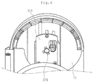
- FIG. 6 is a perspective view showing a condition in which the wheel supporter is coupled with a lower body.
- the wheel supporter 310 includes a fixing portion 311 coupled with the inside of the lower body 11, and a shaft 316 integrally formed by the fixing portion 311 and the inserting. That is, the shaft 316 is first formed, and the fixing portion 311 is integrally provided with the shaft 316 by injecting melted synthetic resins inside a mold in a condition in which the mold corresponding to the fixing portion 311 is formed.
- the shaft 316 is integrally provided with the fixing portion 311, a friction of the relative movement of the shaft 316 and the fixing portion 311 is prevented during the rotation of the wheel body 320, and noise may be reduced.
- the completed fixing portion 311 is provided with support portion 314 which wraps around the perimeter of the shaft 316.
- the support portion 314 protrudes from the fixing portion 311 to a predetermined length to maintain a stably coupled state with the shaft 316.
- the fixing portion 311 is provided with a plurality of hooks 312 so as to be coupled with the lower body 11, and the lower body 11 is provided with a plurality of hooks coupling portion 113 so as to be coupled with the plurality of hooks 312.
- the lower body 11 and the fixing portion 311 are provided with a plurality of fixation members 115 and 313 for fixation of the fixation members, respectively.
- the support portion 314 is provided with a plurality of storage portions 315 for storing a lubricant.
- the plurality of storage portions 315 is formed in a position adjacent to the shaft 316.
- FIG. 7 is showing a partial cross-sectional view showing a condition in which the wheel assembly is coupled with the lower body according to the first embodiment of the present invention.
- the perimeter of the shaft 316 is provided with a coupling groove 316a.
- the coupling groove 316a may be generally formed along the perimeter of the shaft 316.
- the plurality of coupling groove 316a having a predetermined size may be formed at the perimeter of the shaft 316.
- the fixing portion 311 is formed by an injection molding, the fixing portion 311 is provided with a protruded portion 314a inserted into the coupling groove 316a. That is, the protruded portion 314a is formed at inner peripheral surface of the support portion 314.
- the protruded portion 314a is formed in the same number and the same shape as those of the coupling groove 316a.
- the protruded portion 314a is inserted into the coupling groove 316a, which may prevent the shaft 316 from separating from the fixing portion 311.
- the end of the shaft 316 is provided with a fixation portion 316b so as to fix the coupling portion 350.
- the fixation portion 316b may be a groove so to insert the part of the coupling member 350.
- the wheel body 320 is coupled with the shaft 316 at the outer of the lower body 11.
- the wheel body 320 includes a bearing 324 so as to facilitate the rotation of the wheel body 320.
- the bearing 324 is integrally provided with wheel body 320 by a inserting mold. That is, the bearing 324 is first formed, and the wheel body 320 is integrally provided with the bearing 324 by injecting melted synthetic resins inside a mold in a condition in which the mold corresponding to the wheel body 320 is formed.
- the completed wheel body 320 is provided with support portion 322 which wraps around the perimeter of the bearing 324.
- the shaft 316 is inserted into the bearing 324.
- the bearing 324 and the wheel body 320 are rotated about the shaft 316 in a condition in which the shaft 316 is inserted into the bearing 324.
- the bearing 324 is integrally provided with the wheel body 320, such that a friction of the relative movement of the bearing 324 and the wheel body 320 is prevented, thereby reducing the noise.
- the bearing 324 and the shaft 316 may be provided with the same materials.
- the lubricant stored in storage portion 315 of the supporter 310 is applied to a contacted area of the shaft 316 with the bearing 324, such that the bearing 324 may be more smoothly rotated.
- the lower body 11 is provided with a guide portion 111 to guide the rotation of the wheel body 320, and the shaft 316 and the bearing 324 are inserted into the guide portion 111.
- the guide portion 111 is protruded from the lower body 11 outside, and is substantially formed in the size corresponding to the support portion 322.
- the wheel body 320 is provided with a cover portion 326 covering the perimeter of the guide portion 111 in a condition in which the support portion 322 is inserted into the guide portion 111.
- the buffering member 330 is coupled with the circumference of the wheel body 320. That is, the buffering member 330 is formed in a ring shape.
- the buffering member 330 may be formed in rubber materials, for example, - to buffer an impact. However, it is revealed that the materials of the buffering member 330 are not limited.
- the wheel cover 340 is coupled with the wheel body 320 from the outside of the wheel body 320.
- the wheel cover 340 may be, for example, hook coupled with the wheel body 320. If the wheel cover 340 is coupled with the wheel body 320, the wheel cover 340 covers the shaft 316 and the bearing 324.
- the fixing portion 311 is coupled with the lower body 11 by the plurality of hooks 312. If the fixing portion 311 is coupled with the lower body 11, the shaft 316 passes through the guide portion 111.
- the fixation member S is fixed on the fixing portion 311 and the lower body 11.
- the wheel body 320 integrally provided with- the bearing 324 is coupled with the shaft 316. That is, the bearing 324 may be inserted into the guide portion 111. Then, the shaft 316 is inserted into the bearing 324.
- the end of the shaft 316 is protruded outside the bearing 324. Further, the protruded end of the bearing 324 is fixed with the coupling member 350.
- the coupling member 350 may be, for example, an e-ring or c-ring.
- the coupling member 350 is inserted into the fixation portion 316b of the shaft 316.
- the coupling member 350 may prevent the bearing 324 from separating from the guide portion 111 during the rotation of the wheel body 320.
- the assembly of the wheel assembly 30 is completed.
- the coupling of the buffering member and the wheel body may be achieved in any process.
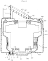
- FIG. 8 is showing a vertical cross-sectional view showing a suction motor assembly according to the first embodiment of the present invention.
- the outer housings 410 and 420 include a lower outer housing 410 coupled with the lower body 11, and a upper outer housing 420 coupled with the upper side of the lower outer housing 410.
- the upper outer housing 420 is provided with an air inlet 421 in which air discharged from the filter unit 220 is introduced.
- the air inlet 421 is protruded from the upper outer housing 420 upwards.
- the air inlet 421 includes an inlet grill 422, and the inlet grill 422 is provided with a plurality of holes 423 through which the air is passed.
- the air inlet portion 421 may be provided with a filter in the upstream or downstream of the air inlet portion 421 (not shown).
- the inner housings 430 and 440 are accommodated in the inside of the outer housings 410 and 420.
- the suction motor 450 is accommodated in the inside of the inner housings 430 and 440.
- the inner housings 430 and 440 includes the lower inner housing 430, and the upper inner housing 440 coupled with the upper side of the lower inner housing 430.
- the upper inner housing 440 is provided with the inlet hole 441 in which the air passed through the air inlet portion 421 is introduced.
- the inlet hole 441 is located at the bottom of the air inlet portion 421.
- the sealer 490 is provided between the upper outer housing 420 and the upper inner housing 440, which may prevent a leakage of air passed through the air inlet portion 421. That is, the sealer 490 prevents the air passed through the air inlet portion 421 from introducing into a space between the upper outer housing 420 and the upper inner housing 440 and guides so as to pass the inlet hole 441.
- the lower inner housing 430 is provided with a plurality of holes 431 through which the air passed through the suction motor 450 is discharged.
- the lower outer housing 410 is formed a discharge unit 416 in which the air passed through the hole 431 is discharged (refer to FIG. 3 ).
- the discharge unit 416 (refer to FIG. 3 ) may be provided with a filter.
- the first suction absorption member 460 includes an upper member 461 attached to the lower side of the suction motor 450, and a lower member 466 provided in the lower side of the upper member 461.
- the first absorption member 460 absorbs the lower vibration of the suction motor 450 and minimizes the vibration of the suction motor 450 transferred to the lower inner housing 430.
- the second absorption member 470 which is coupled with the outer side of the lower inner housing 430, absorbs the lower vibration of the lower inner housing 430 and minimizes the vibration of the lower inner housing 430 transferred to the lower outer housing 410.
- the plurality of second absorption members 470 is coupled with the lower inner housing 430 at the location spaced to each other.
- the third absorption member 480 is duly mounted in the upper side of the suction motor 450 and the part of the third absorption member 480 is inserted into the inlet hole 441 of the upper inner housing 440.
- the third absorption member 480 absorbs the upper vibration of the suction motor 450 and minimizes the upper vibration of the suction motor 450 transferred to the upper inner housing 440.
- the sealer 490 absorbs the vibration of the upper inner housing 440 while preventing the leakage of air, and minimizes the upper vibration of the upper inner housing 440 transferred to the upper outer housing 420.
- each absorption member and the sealer may be formed, for example, the rubber materials, if those have a vibration absorbing function, the materials are not limited.
- FIG. 9 is a perspective view of an upper member which constructs a first absorption member according to the first embodiment of the present invention
- FIG. 10 is a perspective view of a lower member which constructs the first absorption member.
- the upper member 461 is formed in a ring shape. A center part of the upper member 461 is provided with an opening 462 through which a lower part of the suction motor 450 is passed. In addition, the upper member 461 is provided with at least of one coupling holes 463 so as to couple the lower member 466. FIG.9 illustrates that the upper member 461 is provided with two coupling holes 463.
- the upper and lower sides of the upper member 461 are provided with a plurality of protruded portion 464 in the circumferential direction of the upper member 461. Further, the plurality of protruded portion 464 is substantially connected to the lower side of the suction motor 450 and the upper side of the lower member 466.
- the plurality of protruded portions 464 is connected to the lower side of the suction motor 450, such that the contact area of the suction motor 450 and the upper member 461 is reduced, the transmission of vibration may be reduced.
- the vibration absorbing amount of the upper member 461 may be increased.
- a center part of the lower member 466 is provided with the accommodation portion 467 in which the lower part of the suction motor 450 penetrating the upper member 461 is accommodated.
- the inner peripheral surface of the accommodation portion 467 is provided with a plurality of contact portion 467a to which the lower part of the accommodated suction motor 450 is connected.
- the contact portions 467a are formed separately from each other and extend in both directions up and down.
- the plurality of contact portions 467a is connected to the suction motor 450, such that the lower member 466 may directly absorb a downward vibration of the suction motor 450.
- the plurality of contact portions 467a is connected to the suction motor 450, such that the contact area of the suction motor 450 and the lower member 466 is reduced, the transmission of vibration may be reduced.
- the vibration absorbing amount of the lower member 466 may be increased.
- the upper side of the lower member 466 is provided with at least one of coupling protruded portion 468 to which the coupling hole 463 of the upper member 461 is connected.
- the coupling protruded portion 468 is inserted into the suction motor 450 in a condition the coupling hole 463 is penetrated. Therefore, the vibration of the suction motor 450 may be absorbed by the coupling protruded portion 468.
- a vibration transmitted to the coupling protruded portion 468 is primarily absorbed by the coupling protruded portion 468. Then, the vibration may be secondary absorbed by the upper member 461. Therefore, the vibration absorbing amount may be increased.
- the vibration absorbing amount may be increased.
- the first absorption member 460 is configured by an upper member 461 and a lower member 466 connected to each other, such that a vibration absorbing amount may be increased and noise due to the vibration may be reduced.
- the lower member 466 is coupled with hole 432 formed on the bottom of the lower inner housing 430. Therefore, one part of the lower member 466 is duly mounted into the upper side of the bottom of the lower inner housing 430, and other part of the lower member 466 penetrates the hole 432.
- the lower outer housing 410 is provided with the accommodation portion 411 accommodating the bottom part of the lower member 466.
- the lower member 466 is separated from the accommodation portion 411 in a condition where the bottom part of the lower member 466 is accommodated in the accommodation portion 411. That is, a gap of constant interval is formed between the accommodation portion 411 and the lower member 466. Therefore, a vibration of the lower member 466 may be prevented to be directly transmitted to the lower outer housing 410.
- FIG. 11 is showing a perspective view of a absorption suction member according to the first embodiment of the present invention.
- the second absorption member 470 is coupled with coupling portion 434 protruded from the lower inner housing 430.
- the lower outer housing 410 is provided with a insertion groove 412 inserting the second absorption member 470.
- the second absorption member 470 includes a body 471 in which a groove 472 accommodating the coupling portion 434 is formed. The groove 472 is recessed downward from the upper surface the body 471 and then is formed.
- the outer peripheral surface of the body 471 is provided with the plurality of protruded portions 473.
- the plurality of protruded portions 473 is formed separately from each other and is extended in both directions up and down.
- a plurality of holes 474 is penetrated into the body 471.
- the holes 474 are extended in both directions up and down.
- a plurality of contact portion 475 contacting the insertion groove 412 is formed on a bottom surface of the body 471 Therefore, when the second absorption member470 is inserted into the insertion groove 412, the plurality of protruded portions 473 and a plurality of contact portions 475 contact the lower outer housing 410.
- the plurality of protruded portions 473 and a plurality of contact portions 475 is contacted with the lower outer housing 410, such that the contact area of the lower outer housing 410 and the second absorption member 470 is reduced, thereby reducing the vibration transmission.
- the vibration absorbing amount of the second absorption member 470 may be increased.
- the vibration absorbing amount may be more increased.
- FIG. 12 is showing a vertical cross-sectional view showing a suction motor assembly according to a second embodiment of the present invention
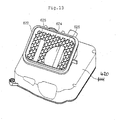
- FIG. 13 is showing a perspective view of an upper outer housing according to the second embodiment of the present invention.
- the second embodiment is the same as the first embodiment, but it is characterized that a configuration to reduce noise is added. Therefore, a characterized part of the second embodiment will be only described hereinafter.
- an absorbent 630 absorbing noise generated during the operation of the suction motor is provided between the upper outer housing 420 and the upper inner housing 434.
- An air inlet 622 in which air discharged from the filter unit of the first embodiment is introduced is provided in the upper outer housing 420.
- the air inlet 622 is protruded from the upper outer housing 420 upwards.
- the air inlet 622 includes a suction grill 624, and a plurality of holes 625 through which the air is passed is provided in the suction grill 624.
- noise reduction portion 626 which reduces the noise during the operation of the suction motor, is provided in the suction grill 624.
- the noise reduction portion 626 changes noise path to move the noise toward the absorbent 630. That is, the noise reduction portion 626 acts as a wall to reflect the noise, and is located on the noise path.
- At least part of the noise reduction portion 626 may be disposed vertically upward of the inlet hole 441 provided at the lower inner housing 440.
- the absorbent 630 is provided around the inlet hole 441. Therefore, after the generated noise from the operation of the suction motor 450 is passed through the inlet hole 411, the noise is impacted against the noise reduction portion 626, the movement direction of the noise is changed, and the noise proceed to the absorbent 630. Therefore, according to the second embodiment, the generated noise from the operation of the suction motor may be reduced.
- the arrow shows the outline of the motion path of the noise.
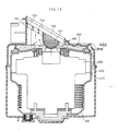
- FIG. 14 illustrates a vertical cross-sectional view showing a suction motor assembly according to a third embodiment of the present invention
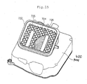
- FIG. 15 illustrates a perspective view of an upper outer housing according to the third embodiment of the present invention.
- the third embodiment is the same as the second embodiment, but a configuration of reducing noise is different. Therefore, a characterized part of the embodiment will be only described hereinafter.
- the air inlet 722 is protruded vertically above from the upper outer housing 420.
- the air inlet 722 includes a suction grill 724, and a plurality of holes 725 through which the air is passed is provided in the suction grill 724.
- the noise reduction portion 726 which reduces the noise from the operation of the suction motor, is provided in the suction grill 724.
- the noise reduction portion 726 is extended from the suction grill 724 to the suction motor 450.
- the bottom part of the noise reduction portion 726 is rounded.
- the plurality of noise reducing holes 727 is disposed in the noise reduction portion 726.
- the plurality of noise reducing holes 727 is disposed to allow passage of air, to change the path of the noise, and to offset the noise.
- a part in which no noise reducing hole 727 is formed in the noise reduction portion 726 is disposed to be moved toward the absorbent 630 by changing the direction of the noise.
- the arrow schematically shows the outline of the motion path of the noise.
- the generated noise from the operation of the suction motor may be reduced by the noise reduction portion 726 itself and the absorbents 630 when operating of the suction motor.
- a vacuum -cleaner of such type as a canister vacuum cleaner is described, the present invention may be applied to a vacuum cleaner or a robot vacuum cleaner such type as an upright.
Landscapes
- Engineering & Computer Science (AREA)
- Mechanical Engineering (AREA)
- Nozzles For Electric Vacuum Cleaners (AREA)
Claims (7)
- Staubsauger mit:einem Staubsaugerkörper (10) mit einer Saugmotoranordnung (40), um eine Saugkraft zu erzeugen, undeiner Radanordnung (30), um ein Bewegen des Staubsaugerkörpers (10) zu vereinfachen,wobei die Radanordnung (30) aufweist:einen Radhalter (310) mit einem Befestigungsteil (311), das mit dem Inneren des Staubsaugerkörpers (10) und einer Welle (316) verbunden ist, die die Mittelrotationsachse darstellt, undeinen Radkörper (320), der mit der Welle (316) außen am Staubsaugerkörper (10) verbunden ist, wobei das Befestigungsteil (311) und die Welle (316) durch Umspritzguss einstückig ausgebildet sind,dadurch gekennzeichnet, dassein mit der Welle (316) zu verbindendes Lager (324) am Radkörper (320) vorgesehen ist und das Lager (324) und der Radkörper (320) durch den Umspritzguss einstückig ausgebildet sind.
- Staubsauger nach Anspruch 1, wobei ein Auflageteil (322), das das Lager (324) lagert, im Radkörper (320) vorgesehen ist, und
ein Führungsteil (111), das eine Drehung des Auflageteils (322) führt, im Staubsaugerkörper (10) vorgesehen ist. - Staubsauger nach Anspruch 1, ferner mit einem Verbindungselement (350), das mit der Welle (316) verbunden ist, um eine Abtrennung des Radkörpers (320) zu verhindern, wenn der Radkörper (320) und die Welle (316) miteinander verbunden sind.
- Staubsauger nach Anspruch 1, wobei das Befestigungsteil (311) ein Auflageteil (314) aufweist, das die Welle (316) lagert, so dass diese vorsteht, und das Auflageteil (314) den Umfang der Welle (316) umgibt.
- Staubsauger nach Anspruch 4, wobei der Umfang der Welle (316) eine Verbindungsnut (316a) aufweist und
das Auflageteil (314) ein vorstehendes Teil (314a) aufweist, das in die Verbindungsnut (316a) eingesetzt wird. - Staubsauger nach Anspruch 5, wobei das vorstehende Teil (314a) in der Innenumfangsfläche des Auflageteils (314) vorgesehen ist.
- Staubsauger nach Anspruch 4, wobei das Auflageteil (314) ein Speicherteil (315) aufweist, das ein auf die Welle (316) aufgebrachtes Schmiermittel speichert.
Applications Claiming Priority (1)
| Application Number | Priority Date | Filing Date | Title |
|---|---|---|---|
| PCT/KR2009/001275 WO2010104229A1 (ko) | 2009-03-13 | 2009-03-13 | 진공 청소기 |
Publications (3)
| Publication Number | Publication Date |
|---|---|
| EP2407073A1 EP2407073A1 (de) | 2012-01-18 |
| EP2407073A4 EP2407073A4 (de) | 2013-02-20 |
| EP2407073B1 true EP2407073B1 (de) | 2019-05-08 |
Family
ID=42728500
Family Applications (1)
| Application Number | Title | Priority Date | Filing Date |
|---|---|---|---|
| EP09841543.3A Active EP2407073B1 (de) | 2009-03-13 | 2009-03-13 | Staubsauger |
Country Status (3)
| Country | Link |
|---|---|
| EP (1) | EP2407073B1 (de) |
| AU (1) | AU2009341752B2 (de) |
| WO (1) | WO2010104229A1 (de) |
Families Citing this family (1)
| Publication number | Priority date | Publication date | Assignee | Title |
|---|---|---|---|---|
| JP6058506B2 (ja) * | 2013-08-23 | 2017-01-11 | 日立アプライアンス株式会社 | 電気掃除機 |
Family Cites Families (6)
| Publication number | Priority date | Publication date | Assignee | Title |
|---|---|---|---|---|
| JP2573367B2 (ja) * | 1989-09-05 | 1997-01-22 | 三菱電機ホーム機器株式会社 | 電気掃除機 |
| US5115537A (en) * | 1989-11-29 | 1992-05-26 | The Scott Fetzer Company | Drive system |
| JPH03184857A (ja) * | 1989-12-14 | 1991-08-12 | Ricoh Co Ltd | 有機化合物の光粘性効果を利用した記録装置 |
| US5249328A (en) * | 1990-03-20 | 1993-10-05 | Goldstar Co., Ltd. | Vacuum cleaner beater brush structure |
| US5222786A (en) * | 1992-01-10 | 1993-06-29 | Royal Appliance Mfg. Co. | Wheel construction for vacuum cleaner |
| JP3184857B2 (ja) * | 1994-07-15 | 2001-07-09 | 東芝テック株式会社 | 電気掃除機 |
-
2009
- 2009-03-13 EP EP09841543.3A patent/EP2407073B1/de active Active
- 2009-03-13 WO PCT/KR2009/001275 patent/WO2010104229A1/ko not_active Ceased
- 2009-03-13 AU AU2009341752A patent/AU2009341752B2/en not_active Ceased
Non-Patent Citations (1)
| Title |
|---|
| None * |
Also Published As
| Publication number | Publication date |
|---|---|
| WO2010104229A1 (ko) | 2010-09-16 |
| AU2009341752B2 (en) | 2016-04-14 |
| AU2009341752A1 (en) | 2011-09-01 |
| EP2407073A4 (de) | 2013-02-20 |
| EP2407073A1 (de) | 2012-01-18 |
Similar Documents
| Publication | Publication Date | Title |
|---|---|---|
| KR102560212B1 (ko) | 청소기의 노즐 | |
| TWI664944B (zh) | 真空吸塵器 | |
| TWI643594B (zh) | 真空吸塵器 | |
| TWI641351B (zh) | 真空吸塵器 | |
| TWI637718B (zh) | 真空吸塵器 | |
| KR102274418B1 (ko) | 필터 카트리지 및 에어 필터 조립체 | |
| US8673042B2 (en) | Filter element and filter device | |
| US20160220935A1 (en) | Hollow Filter Element, Grip Device of a Hollow Filter Element, and Filter Device with at Least One Hollow Filter Element | |
| EP2826410A1 (de) | Staubsauger | |
| JP2008544151A (ja) | フィルタハウジングを備えたフィルタ装置 | |
| TW201731433A (zh) | 真空吸塵器 | |
| TW201731445A (zh) | 真空吸塵器 | |
| CN112568784A (zh) | 真空吸尘器 | |
| CN107002598A (zh) | 过滤装置、过滤元件和过滤装置的维护过程 | |
| EP2862492A1 (de) | Staubsauger | |
| KR20140030059A (ko) | 전기 청소기 | |
| AU2009341752B2 (en) | Vacuum cleaner | |
| EP3960060A1 (de) | Reiniger | |
| JP2010273872A (ja) | 吸込口体および電気掃除機 | |
| CN211511639U (zh) | 用于家用吸尘器的吸入装置以及包括其的家用吸尘器 | |
| CN103096774A (zh) | 集尘装置和电动吸尘器 | |
| CN106996351A (zh) | 用于内燃机的空气滤清器 | |
| CN211511624U (zh) | 吸入装置、家用吸尘器以及气动密封元件 | |
| EP2306878B1 (de) | Staubsauger | |
| CN105996904B (zh) | 一种吸尘器过滤袋支撑架 |
Legal Events
| Date | Code | Title | Description |
|---|---|---|---|
| PUAI | Public reference made under article 153(3) epc to a published international application that has entered the european phase |
Free format text: ORIGINAL CODE: 0009012 |
|
| 17P | Request for examination filed |
Effective date: 20110831 |
|
| AK | Designated contracting states |
Kind code of ref document: A1 Designated state(s): AT BE BG CH CY CZ DE DK EE ES FI FR GB GR HR HU IE IS IT LI LT LU LV MC MK MT NL NO PL PT RO SE SI SK TR |
|
| DAX | Request for extension of the european patent (deleted) | ||
| RIN1 | Information on inventor provided before grant (corrected) |
Inventor name: LEE, CHANG-OOK Inventor name: SEO, JONG-HYUN |
|
| A4 | Supplementary search report drawn up and despatched |
Effective date: 20130121 |
|
| RIC1 | Information provided on ipc code assigned before grant |
Ipc: A47L 5/08 20060101ALI20130115BHEP Ipc: A47L 9/00 20060101AFI20130115BHEP |
|
| GRAP | Despatch of communication of intention to grant a patent |
Free format text: ORIGINAL CODE: EPIDOSNIGR1 |
|
| STAA | Information on the status of an ep patent application or granted ep patent |
Free format text: STATUS: GRANT OF PATENT IS INTENDED |
|
| INTG | Intention to grant announced |
Effective date: 20181109 |
|
| GRAS | Grant fee paid |
Free format text: ORIGINAL CODE: EPIDOSNIGR3 |
|
| GRAA | (expected) grant |
Free format text: ORIGINAL CODE: 0009210 |
|
| STAA | Information on the status of an ep patent application or granted ep patent |
Free format text: STATUS: THE PATENT HAS BEEN GRANTED |
|
| RAP1 | Party data changed (applicant data changed or rights of an application transferred) |
Owner name: LG ELECTRONICS INC. |
|
| AK | Designated contracting states |
Kind code of ref document: B1 Designated state(s): AT BE BG CH CY CZ DE DK EE ES FI FR GB GR HR HU IE IS IT LI LT LU LV MC MK MT NL NO PL PT RO SE SI SK TR |
|
| REG | Reference to a national code |
Ref country code: GB Ref legal event code: FG4D |
|
| REG | Reference to a national code |
Ref country code: CH Ref legal event code: EP Ref country code: AT Ref legal event code: REF Ref document number: 1128869 Country of ref document: AT Kind code of ref document: T Effective date: 20190515 |
|
| REG | Reference to a national code |
Ref country code: DE Ref legal event code: R096 Ref document number: 602009058303 Country of ref document: DE |
|
| REG | Reference to a national code |
Ref country code: IE Ref legal event code: FG4D |
|
| REG | Reference to a national code |
Ref country code: NL Ref legal event code: FP |
|
| REG | Reference to a national code |
Ref country code: LT Ref legal event code: MG4D |
|
| PG25 | Lapsed in a contracting state [announced via postgrant information from national office to epo] |
Ref country code: SE Free format text: LAPSE BECAUSE OF FAILURE TO SUBMIT A TRANSLATION OF THE DESCRIPTION OR TO PAY THE FEE WITHIN THE PRESCRIBED TIME-LIMIT Effective date: 20190508 Ref country code: LT Free format text: LAPSE BECAUSE OF FAILURE TO SUBMIT A TRANSLATION OF THE DESCRIPTION OR TO PAY THE FEE WITHIN THE PRESCRIBED TIME-LIMIT Effective date: 20190508 Ref country code: ES Free format text: LAPSE BECAUSE OF FAILURE TO SUBMIT A TRANSLATION OF THE DESCRIPTION OR TO PAY THE FEE WITHIN THE PRESCRIBED TIME-LIMIT Effective date: 20190508 Ref country code: FI Free format text: LAPSE BECAUSE OF FAILURE TO SUBMIT A TRANSLATION OF THE DESCRIPTION OR TO PAY THE FEE WITHIN THE PRESCRIBED TIME-LIMIT Effective date: 20190508 Ref country code: PT Free format text: LAPSE BECAUSE OF FAILURE TO SUBMIT A TRANSLATION OF THE DESCRIPTION OR TO PAY THE FEE WITHIN THE PRESCRIBED TIME-LIMIT Effective date: 20190908 Ref country code: NO Free format text: LAPSE BECAUSE OF FAILURE TO SUBMIT A TRANSLATION OF THE DESCRIPTION OR TO PAY THE FEE WITHIN THE PRESCRIBED TIME-LIMIT Effective date: 20190808 Ref country code: HR Free format text: LAPSE BECAUSE OF FAILURE TO SUBMIT A TRANSLATION OF THE DESCRIPTION OR TO PAY THE FEE WITHIN THE PRESCRIBED TIME-LIMIT Effective date: 20190508 |
|
| PG25 | Lapsed in a contracting state [announced via postgrant information from national office to epo] |
Ref country code: GR Free format text: LAPSE BECAUSE OF FAILURE TO SUBMIT A TRANSLATION OF THE DESCRIPTION OR TO PAY THE FEE WITHIN THE PRESCRIBED TIME-LIMIT Effective date: 20190809 Ref country code: LV Free format text: LAPSE BECAUSE OF FAILURE TO SUBMIT A TRANSLATION OF THE DESCRIPTION OR TO PAY THE FEE WITHIN THE PRESCRIBED TIME-LIMIT Effective date: 20190508 Ref country code: BG Free format text: LAPSE BECAUSE OF FAILURE TO SUBMIT A TRANSLATION OF THE DESCRIPTION OR TO PAY THE FEE WITHIN THE PRESCRIBED TIME-LIMIT Effective date: 20190808 |
|
| REG | Reference to a national code |
Ref country code: AT Ref legal event code: MK05 Ref document number: 1128869 Country of ref document: AT Kind code of ref document: T Effective date: 20190508 |
|
| PG25 | Lapsed in a contracting state [announced via postgrant information from national office to epo] |
Ref country code: DK Free format text: LAPSE BECAUSE OF FAILURE TO SUBMIT A TRANSLATION OF THE DESCRIPTION OR TO PAY THE FEE WITHIN THE PRESCRIBED TIME-LIMIT Effective date: 20190508 Ref country code: AT Free format text: LAPSE BECAUSE OF FAILURE TO SUBMIT A TRANSLATION OF THE DESCRIPTION OR TO PAY THE FEE WITHIN THE PRESCRIBED TIME-LIMIT Effective date: 20190508 Ref country code: EE Free format text: LAPSE BECAUSE OF FAILURE TO SUBMIT A TRANSLATION OF THE DESCRIPTION OR TO PAY THE FEE WITHIN THE PRESCRIBED TIME-LIMIT Effective date: 20190508 Ref country code: RO Free format text: LAPSE BECAUSE OF FAILURE TO SUBMIT A TRANSLATION OF THE DESCRIPTION OR TO PAY THE FEE WITHIN THE PRESCRIBED TIME-LIMIT Effective date: 20190508 Ref country code: CZ Free format text: LAPSE BECAUSE OF FAILURE TO SUBMIT A TRANSLATION OF THE DESCRIPTION OR TO PAY THE FEE WITHIN THE PRESCRIBED TIME-LIMIT Effective date: 20190508 Ref country code: SK Free format text: LAPSE BECAUSE OF FAILURE TO SUBMIT A TRANSLATION OF THE DESCRIPTION OR TO PAY THE FEE WITHIN THE PRESCRIBED TIME-LIMIT Effective date: 20190508 |
|
| REG | Reference to a national code |
Ref country code: DE Ref legal event code: R097 Ref document number: 602009058303 Country of ref document: DE |
|
| PG25 | Lapsed in a contracting state [announced via postgrant information from national office to epo] |
Ref country code: IT Free format text: LAPSE BECAUSE OF FAILURE TO SUBMIT A TRANSLATION OF THE DESCRIPTION OR TO PAY THE FEE WITHIN THE PRESCRIBED TIME-LIMIT Effective date: 20190508 |
|
| PLBE | No opposition filed within time limit |
Free format text: ORIGINAL CODE: 0009261 |
|
| STAA | Information on the status of an ep patent application or granted ep patent |
Free format text: STATUS: NO OPPOSITION FILED WITHIN TIME LIMIT |
|
| PG25 | Lapsed in a contracting state [announced via postgrant information from national office to epo] |
Ref country code: TR Free format text: LAPSE BECAUSE OF FAILURE TO SUBMIT A TRANSLATION OF THE DESCRIPTION OR TO PAY THE FEE WITHIN THE PRESCRIBED TIME-LIMIT Effective date: 20190508 |
|
| 26N | No opposition filed |
Effective date: 20200211 |
|
| PG25 | Lapsed in a contracting state [announced via postgrant information from national office to epo] |
Ref country code: PL Free format text: LAPSE BECAUSE OF FAILURE TO SUBMIT A TRANSLATION OF THE DESCRIPTION OR TO PAY THE FEE WITHIN THE PRESCRIBED TIME-LIMIT Effective date: 20190508 |
|
| PGFP | Annual fee paid to national office [announced via postgrant information from national office to epo] |
Ref country code: GB Payment date: 20200213 Year of fee payment: 12 |
|
| PG25 | Lapsed in a contracting state [announced via postgrant information from national office to epo] |
Ref country code: SI Free format text: LAPSE BECAUSE OF FAILURE TO SUBMIT A TRANSLATION OF THE DESCRIPTION OR TO PAY THE FEE WITHIN THE PRESCRIBED TIME-LIMIT Effective date: 20190508 |
|
| PG25 | Lapsed in a contracting state [announced via postgrant information from national office to epo] |
Ref country code: MC Free format text: LAPSE BECAUSE OF FAILURE TO SUBMIT A TRANSLATION OF THE DESCRIPTION OR TO PAY THE FEE WITHIN THE PRESCRIBED TIME-LIMIT Effective date: 20190508 |
|
| REG | Reference to a national code |
Ref country code: CH Ref legal event code: PL |
|
| REG | Reference to a national code |
Ref country code: NL Ref legal event code: MM Effective date: 20200401 |
|
| REG | Reference to a national code |
Ref country code: BE Ref legal event code: MM Effective date: 20200331 |
|
| PG25 | Lapsed in a contracting state [announced via postgrant information from national office to epo] |
Ref country code: LU Free format text: LAPSE BECAUSE OF NON-PAYMENT OF DUE FEES Effective date: 20200313 Ref country code: NL Free format text: LAPSE BECAUSE OF NON-PAYMENT OF DUE FEES Effective date: 20200401 |
|
| PG25 | Lapsed in a contracting state [announced via postgrant information from national office to epo] |
Ref country code: CH Free format text: LAPSE BECAUSE OF NON-PAYMENT OF DUE FEES Effective date: 20200331 Ref country code: LI Free format text: LAPSE BECAUSE OF NON-PAYMENT OF DUE FEES Effective date: 20200331 Ref country code: IE Free format text: LAPSE BECAUSE OF NON-PAYMENT OF DUE FEES Effective date: 20200313 Ref country code: FR Free format text: LAPSE BECAUSE OF NON-PAYMENT OF DUE FEES Effective date: 20200331 |
|
| PG25 | Lapsed in a contracting state [announced via postgrant information from national office to epo] |
Ref country code: BE Free format text: LAPSE BECAUSE OF NON-PAYMENT OF DUE FEES Effective date: 20200331 |
|
| GBPC | Gb: european patent ceased through non-payment of renewal fee |
Effective date: 20210313 |
|
| PG25 | Lapsed in a contracting state [announced via postgrant information from national office to epo] |
Ref country code: GB Free format text: LAPSE BECAUSE OF NON-PAYMENT OF DUE FEES Effective date: 20210313 |
|
| PGFP | Annual fee paid to national office [announced via postgrant information from national office to epo] |
Ref country code: DE Payment date: 20220207 Year of fee payment: 14 |
|
| PG25 | Lapsed in a contracting state [announced via postgrant information from national office to epo] |
Ref country code: MT Free format text: LAPSE BECAUSE OF FAILURE TO SUBMIT A TRANSLATION OF THE DESCRIPTION OR TO PAY THE FEE WITHIN THE PRESCRIBED TIME-LIMIT Effective date: 20190508 Ref country code: CY Free format text: LAPSE BECAUSE OF FAILURE TO SUBMIT A TRANSLATION OF THE DESCRIPTION OR TO PAY THE FEE WITHIN THE PRESCRIBED TIME-LIMIT Effective date: 20190508 |
|
| PG25 | Lapsed in a contracting state [announced via postgrant information from national office to epo] |
Ref country code: MK Free format text: LAPSE BECAUSE OF FAILURE TO SUBMIT A TRANSLATION OF THE DESCRIPTION OR TO PAY THE FEE WITHIN THE PRESCRIBED TIME-LIMIT Effective date: 20190508 Ref country code: IS Free format text: LAPSE BECAUSE OF FAILURE TO SUBMIT A TRANSLATION OF THE DESCRIPTION OR TO PAY THE FEE WITHIN THE PRESCRIBED TIME-LIMIT Effective date: 20190908 |
|
| REG | Reference to a national code |
Ref country code: DE Ref legal event code: R119 Ref document number: 602009058303 Country of ref document: DE |
|
| PG25 | Lapsed in a contracting state [announced via postgrant information from national office to epo] |
Ref country code: DE Free format text: LAPSE BECAUSE OF NON-PAYMENT OF DUE FEES Effective date: 20231003 |