EP2406808B1 - Method for assembling an electron exit window and an electron exit window assembly - Google Patents
Method for assembling an electron exit window and an electron exit window assembly Download PDFInfo
- Publication number
- EP2406808B1 EP2406808B1 EP10751075.2A EP10751075A EP2406808B1 EP 2406808 B1 EP2406808 B1 EP 2406808B1 EP 10751075 A EP10751075 A EP 10751075A EP 2406808 B1 EP2406808 B1 EP 2406808B1
- Authority
- EP
- European Patent Office
- Prior art keywords
- foil
- support plate
- housing
- skirt
- exit window
- Prior art date
- Legal status (The legal status is an assumption and is not a legal conclusion. Google has not performed a legal analysis and makes no representation as to the accuracy of the status listed.)
- Not-in-force
Links
- 238000000034 method Methods 0.000 title claims description 17
- 239000011888 foil Substances 0.000 claims description 53
- 238000010894 electron beam technology Methods 0.000 claims description 23
- 238000009792 diffusion process Methods 0.000 claims description 4
- 238000004026 adhesive bonding Methods 0.000 claims description 3
- 230000000063 preceeding effect Effects 0.000 claims 3
- RYGMFSIKBFXOCR-UHFFFAOYSA-N Copper Chemical compound [Cu] RYGMFSIKBFXOCR-UHFFFAOYSA-N 0.000 description 12
- 239000010949 copper Substances 0.000 description 11
- 229910052802 copper Inorganic materials 0.000 description 11
- MHAJPDPJQMAIIY-UHFFFAOYSA-N Hydrogen peroxide Chemical compound OO MHAJPDPJQMAIIY-UHFFFAOYSA-N 0.000 description 6
- 239000003292 glue Substances 0.000 description 5
- 238000005260 corrosion Methods 0.000 description 4
- 230000007797 corrosion Effects 0.000 description 4
- 238000003466 welding Methods 0.000 description 4
- CBENFWSGALASAD-UHFFFAOYSA-N Ozone Chemical compound [O-][O+]=O CBENFWSGALASAD-UHFFFAOYSA-N 0.000 description 2
- RTAQQCXQSZGOHL-UHFFFAOYSA-N Titanium Chemical compound [Ti] RTAQQCXQSZGOHL-UHFFFAOYSA-N 0.000 description 2
- 238000005219 brazing Methods 0.000 description 2
- 239000003518 caustics Substances 0.000 description 2
- 238000000576 coating method Methods 0.000 description 2
- 230000001419 dependent effect Effects 0.000 description 2
- 238000004519 manufacturing process Methods 0.000 description 2
- 230000001954 sterilising effect Effects 0.000 description 2
- 238000004659 sterilization and disinfection Methods 0.000 description 2
- 239000010936 titanium Substances 0.000 description 2
- 229910052719 titanium Inorganic materials 0.000 description 2
- QVGXLLKOCUKJST-UHFFFAOYSA-N atomic oxygen Chemical compound [O] QVGXLLKOCUKJST-UHFFFAOYSA-N 0.000 description 1
- 239000011889 copper foil Substances 0.000 description 1
- 230000003467 diminishing effect Effects 0.000 description 1
- 239000007789 gas Substances 0.000 description 1
- 239000000463 material Substances 0.000 description 1
- 238000012986 modification Methods 0.000 description 1
- 230000004048 modification Effects 0.000 description 1
- 239000001301 oxygen Substances 0.000 description 1
- 229910052760 oxygen Inorganic materials 0.000 description 1
- 238000004806 packaging method and process Methods 0.000 description 1
- 238000007493 shaping process Methods 0.000 description 1
- 229910001220 stainless steel Inorganic materials 0.000 description 1
- 239000010935 stainless steel Substances 0.000 description 1
- 238000009966 trimming Methods 0.000 description 1
Images

Classifications
-
- G—PHYSICS
- G21—NUCLEAR PHYSICS; NUCLEAR ENGINEERING
- G21K—TECHNIQUES FOR HANDLING PARTICLES OR IONISING RADIATION NOT OTHERWISE PROVIDED FOR; IRRADIATION DEVICES; GAMMA RAY OR X-RAY MICROSCOPES
- G21K5/00—Irradiation devices
- G21K5/02—Irradiation devices having no beam-forming means
-
- G—PHYSICS
- G21—NUCLEAR PHYSICS; NUCLEAR ENGINEERING
- G21K—TECHNIQUES FOR HANDLING PARTICLES OR IONISING RADIATION NOT OTHERWISE PROVIDED FOR; IRRADIATION DEVICES; GAMMA RAY OR X-RAY MICROSCOPES
- G21K5/00—Irradiation devices
- G21K5/04—Irradiation devices with beam-forming means
-
- H—ELECTRICITY
- H01—ELECTRIC ELEMENTS
- H01J—ELECTRIC DISCHARGE TUBES OR DISCHARGE LAMPS
- H01J33/00—Discharge tubes with provision for emergence of electrons or ions from the vessel; Lenard tubes
- H01J33/02—Details
- H01J33/04—Windows
-
- Y—GENERAL TAGGING OF NEW TECHNOLOGICAL DEVELOPMENTS; GENERAL TAGGING OF CROSS-SECTIONAL TECHNOLOGIES SPANNING OVER SEVERAL SECTIONS OF THE IPC; TECHNICAL SUBJECTS COVERED BY FORMER USPC CROSS-REFERENCE ART COLLECTIONS [XRACs] AND DIGESTS
- Y10—TECHNICAL SUBJECTS COVERED BY FORMER USPC
- Y10T—TECHNICAL SUBJECTS COVERED BY FORMER US CLASSIFICATION
- Y10T156/00—Adhesive bonding and miscellaneous chemical manufacture
- Y10T156/10—Methods of surface bonding and/or assembly therefor
Definitions
- the present invention refers to a method for assembling an electron exit window and an electron exit window assembly.
- Electron beam generating devices may be used in sterilization of items, such as for example in sterilization of food packages or medical equipment, or they may be used in curing of e.g. ink.
- these devices comprise an electron exit window formed by a foil and a foil support plate.
- the support plate which is preferably made of copper, has a plurality of apertures through which the electrons will exit from the electron beam generating device during operation.
- the foil may have a thickness of around 6-10 ⁇ m and may be made of titanium. Due to the thinness most of the electrons are able to pass through it.
- the present invention primarily relates to electron beam generation devices used for irradiation of webs of material, i.e., electron beam generation devices having relatively large electron exit windows.
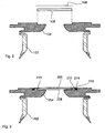
- the electron beam device 100 comprises two parts; a tube body 102 housing and protecting the assembly 103 generating and shaping the electron beam, and a flange 104 carrying components relating to the output of the electron beam, such as the window foil 106 and the foil support plate 108 preventing the window foil 106 from collapsing as vacuum is established inside the device 100. Further, during operation of the electron beam device the foil is subject to excessive heat. Thereby, the foil support plate 108 also serves the important purpose of conducting heat generated in the foil 106 during use away from the foil of the device. By keeping the foil temperature moderate a sufficiently long lifetime of the foil 106 may be obtained.
- the support plate 108 being of copper, is bonded to the flange 104, which is separate from the tube body 102 at this stage.
- the flange 104 is generally made of stainless steel.
- the window foil 106 is then bonded onto the foil support plate 108 along a line extending along the perimeter of the foil support plate 108 (not shown, but the bonding is made at a similar point as the bonding line 210 in Fig. 3 ), and excess window foil 106 is trimmed off.
- the foil 106 may subsequently be coated, in order to improve its properties regarding for instance heat transfer.
- the flange 104 is subsequently attached to the tube body 102 to form a sealed housing.
- the inventors of the present invention have discovered that this prior solution is not optimal when the electron beam device is used in for example oxygen containing atmospheres. Under these circumstances the accelerated electrons will generate ozone, which is a highly corrosive substance. The ozone may corrode the copper support, which may in turn compromise the seal of the housing and the function of the electron beam device.
- hydrogen peroxide is often used to sterilize the machine parts before production of packages starts. Thus, the copper support may come into contact with hydrogen peroxide as well. Hydrogen peroxide is also highly corrosive for the copper support.
- the most sensitive location is the copper volume at the bonding line with the foil 106.
- the corrosion only needs to work underneath the bonding line, which is only a few tenths of a millimetre, in order to result in the unfortunate result described above.
- the present invention aims at solving this problem by providing a method for assembling an electron exit window of an electron beam generating device, comprising the steps of arranging a foil support plate on a housing of the electron beam generating device, bonding a window foil to the foil support plate along at least one continuous bonding line, attaching a skirt of said window foil extending radially outside of the at least one bonding line to the housing along at least one continuous attachment line.
- the attachement of the foil to the housing will provide a seal, which will protect the copper support plate from being subjected to corrosive substances, which may cause corrosion and failing sealability.
- the invention also comprises an electron exit window assembly of an electron beam generating device comprising a foil support plate and a window foil, wherein said foil support plate is attached to a housing of the electron beam generating device, said window foil is bonded to the foil support plate along at least one continuous bonding line, and a skirt of said window foil, extending radially outside of the at least one bonding line, is attached to the housing along at least one continuous attachment line.
- Figs. 1 and 2 have already been described.
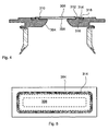
- Fig. 3 is a cross section similar to Fig. 2 , but not exploded, of a first embodiment of the present invention.
- the similarity of Fig. 2 and Fig. 3 is intentional, in order to simplify understanding of the present invention.
- the similarity should not, however, be construed as diminishing the inventiveness of the present invention since there is more to it than meets the eye.
- the copper support 208 is bonded to the flange 204.
- One possible bonding technique is brazing.
- the window foil 206 made of titanium, is bonded onto the copper support 208.
- Possible bonding techniques may be for example laser welding, electron beam welding, brazing, ultrasonic welding, diffusion bonding and gluing.
- the bonding is made along a bonding line 210 at the circumference of the copper support 208.
- the bonding technique is diffusion bonding.
- the bonding line 210 is continuous to be able to maintain vacuum inside the electron beam device.
- continuous is used to define that the line is endless or closed. Further, it should be defined that the bonding line 210 extends along the perimeter of the support plate 208.
- the bonding line 210 extends at a distance from the perimeter of the frame support plate 208. Furthermore, at least one bonding line 210 is made. Thus, two or more bonding lines may be made. For example, an inner and an outer bonding line may be made, and the two lines may, for instance, be concentric with each other.
- the flange 204, the copper support 208 and the foil 206 form a window sub-assembly.
- the foil 206 may then optionally be coated and in the coating process only the window sub-assembly needs to be processed.
- the flange 204 is bonded to the tube body 202.
- One possible bonding technique is for example plasma welding.
- a circumferential skirt 212 is left untouched.
- the free end of the skirt 212 is subsequently arranged in a groove 216 in the flange 204, where a glue 214 is applied.
- the glue will function as a gas and moisture seal and as such prevent harmful corrosion of the sensitive volume around the bonding line 210.
- the glue is preferably a high temperature resistant glue.
- the groove 216 is continuous and forms a continuous attachment line for the skirt 212. Further, the groove 216 is positioned at a distance from the perimeter of a hole configuration in the flange 204 over which hole configuration the support plate 208 is attached and through which hole configuration the electrons are arranged to pass.
- a second embodiment is shown in Fig. 4 .
- the support plate 308 is attached to the flange 304, and the foil 306 is bonded to the support plate 308 along a bonding line 310, in ways similar to that of the first embodiment.
- the difference is that the groove 316 may be large enough to receive a frame 318 on top of the foil skirt 312. Said frame 318 will facilitate tying down the skirt 312 towards the flange 304.
- Glue 314 is used to attach the frame 318 in the groove 316.
- the frame 318 is preferably continuous.
- the skirt extending radially outside of the bonding line may be attached directly to the housing without a groove.
- the frame which can be used for tying down the skirt, may be attached directly to the housing.
Landscapes
- Physics & Mathematics (AREA)
- Engineering & Computer Science (AREA)
- General Engineering & Computer Science (AREA)
- High Energy & Nuclear Physics (AREA)
- Apparatus For Disinfection Or Sterilisation (AREA)
- Physical Or Chemical Processes And Apparatus (AREA)
- Particle Accelerators (AREA)
Applications Claiming Priority (3)
| Application Number | Priority Date | Filing Date | Title |
|---|---|---|---|
| SE0900316A SE534156C2 (sv) | 2009-03-11 | 2009-03-11 | Förfarande för montering av ett fönster för utgående elektroner och en fönsterenhet för utgående elektroner |
| US16013109P | 2009-03-13 | 2009-03-13 | |
| PCT/SE2010/000018 WO2010104439A1 (en) | 2009-03-11 | 2010-01-27 | Method for assembling an electron exit window and an electron exit window assembly |
Publications (3)
| Publication Number | Publication Date |
|---|---|
| EP2406808A1 EP2406808A1 (en) | 2012-01-18 |
| EP2406808A4 EP2406808A4 (en) | 2013-06-26 |
| EP2406808B1 true EP2406808B1 (en) | 2014-05-21 |
Family
ID=42728554
Family Applications (1)
| Application Number | Title | Priority Date | Filing Date |
|---|---|---|---|
| EP10751075.2A Not-in-force EP2406808B1 (en) | 2009-03-11 | 2010-01-27 | Method for assembling an electron exit window and an electron exit window assembly |
Country Status (6)
| Country | Link |
|---|---|
| US (1) | US9183963B2 (enExample) |
| EP (1) | EP2406808B1 (enExample) |
| JP (1) | JP2012520457A (enExample) |
| CN (1) | CN102341885B (enExample) |
| SE (1) | SE534156C2 (enExample) |
| WO (1) | WO2010104439A1 (enExample) |
Families Citing this family (8)
| Publication number | Priority date | Publication date | Assignee | Title |
|---|---|---|---|---|
| SE533567C2 (sv) * | 2009-03-11 | 2010-10-26 | Tetra Laval Holdings & Finance | Förfarande för montering av ett fönster för utgående elektroner och en fönsterenhet för utgående elektroner |
| CN103620726B (zh) | 2011-07-04 | 2016-12-28 | 利乐拉瓦尔集团及财务有限公司 | 一种电子束装置、吸气器片和制造装配有所述吸气器片的电子束装置的方法 |
| US9078747B2 (en) | 2011-12-21 | 2015-07-14 | Edwards Lifesciences Corporation | Anchoring device for replacing or repairing a heart valve |
| CN102881545B (zh) * | 2012-09-18 | 2016-01-20 | 中国科学院上海应用物理研究所 | 电子射线源产生装置及产生低剂量率电子射线的方法 |
| CN103077762B (zh) * | 2012-12-19 | 2016-09-28 | 中国科学院上海应用物理研究所 | 电子射线源产生装置及产生低剂量率电子射线的方法 |
| RU2648241C2 (ru) * | 2016-09-01 | 2018-03-23 | Акционерное Общество "Нииэфа Им. Д.В. Ефремова" | Широкоапертурный ускоритель с планарной электронно-оптической системой |
| EP3574720A4 (en) * | 2017-01-26 | 2020-11-11 | Canadian Light Source Inc. | ELECTRON BEAM EXIT WINDOW FOR ISOTOPE PRODUCTION |
| CN112271128B (zh) * | 2020-11-13 | 2025-04-01 | 黄石上方检测设备有限公司 | 一种横向真空电子束管 |
Family Cites Families (9)
| Publication number | Priority date | Publication date | Assignee | Title |
|---|---|---|---|---|
| DE4219562C1 (enExample) * | 1992-06-15 | 1993-07-15 | Fraunhofer-Gesellschaft Zur Foerderung Der Angewandten Forschung Ev, 8000 Muenchen, De | |
| US5391958A (en) | 1993-04-12 | 1995-02-21 | Charged Injection Corporation | Electron beam window devices and methods of making same |
| US5621270A (en) * | 1995-03-22 | 1997-04-15 | Litton Systems, Inc. | Electron window for toxic remediation device with a support grid having diverging angle holes |
| US5962995A (en) | 1997-01-02 | 1999-10-05 | Applied Advanced Technologies, Inc. | Electron beam accelerator |
| JP3586411B2 (ja) * | 2000-04-25 | 2004-11-10 | 三菱電機株式会社 | 放射線源格納装置 |
| JP2007509462A (ja) * | 2003-10-07 | 2007-04-12 | コーニンクレッカ フィリップス エレクトロニクス エヌ ヴィ | 特にx線源の電子ビームの電子のために透明な窓を製造する方法 |
| JP2005156285A (ja) * | 2003-11-25 | 2005-06-16 | Nhv Corporation | 電子線照射装置 |
| KR100577473B1 (ko) * | 2004-03-09 | 2006-05-10 | 한국원자력연구소 | 전계방출팁을 이용한 저에너지 대면적 전자빔 조사장치 |
| JP4584851B2 (ja) * | 2006-03-10 | 2010-11-24 | 浜松ホトニクス株式会社 | 電子線発生装置 |
-
2009
- 2009-03-11 SE SE0900316A patent/SE534156C2/sv not_active IP Right Cessation
-
2010
- 2010-01-27 EP EP10751075.2A patent/EP2406808B1/en not_active Not-in-force
- 2010-01-27 JP JP2011553981A patent/JP2012520457A/ja active Pending
- 2010-01-27 US US13/255,297 patent/US9183963B2/en active Active
- 2010-01-27 CN CN201080010766.8A patent/CN102341885B/zh active Active
- 2010-01-27 WO PCT/SE2010/000018 patent/WO2010104439A1/en not_active Ceased
Also Published As
| Publication number | Publication date |
|---|---|
| SE534156C2 (sv) | 2011-05-17 |
| US20120087842A1 (en) | 2012-04-12 |
| EP2406808A1 (en) | 2012-01-18 |
| JP2012520457A (ja) | 2012-09-06 |
| CN102341885B (zh) | 2016-06-08 |
| EP2406808A4 (en) | 2013-06-26 |
| US9183963B2 (en) | 2015-11-10 |
| WO2010104439A1 (en) | 2010-09-16 |
| CN102341885A (zh) | 2012-02-01 |
| SE0900316A1 (sv) | 2010-09-12 |
Similar Documents
| Publication | Publication Date | Title |
|---|---|---|
| EP2406808B1 (en) | Method for assembling an electron exit window and an electron exit window assembly | |
| US10032596B2 (en) | Method for assembling an electron exit window and an electron exit window assembly | |
| JP5908492B2 (ja) | 電子射出窓箔、電子ビーム発生器、電子射出窓箔を提供するための方法及び高性能電子ビームデバイスを提供するための方法 | |
| US8110974B2 (en) | Electron beam generating apparatus | |
| WO2009066732A1 (ja) | 放射線検出器及びその製造方法 | |
| JP4234546B2 (ja) | 真空密閉容器及びその製造方法 | |
| WO2005029531A1 (ja) | X線管 | |
| US9659742B2 (en) | X-ray tube and method of manufacturing the same | |
| EP1178841B1 (en) | Method for circuit protection during radiation sterilization | |
| US9412550B2 (en) | Electron beam device, a getter sheet and a method of manufacturing an electron beam device provided with said getter sheet | |
| HK1166419A (en) | Method for assembling an electron exit window and an electron exit window assembly | |
| JP3931888B2 (ja) | 真空パッケージの製造方法 | |
| CA2571151A1 (en) | Process for encapsulation of cellulose based substrate using non-electromagnetic heating | |
| KR102606388B1 (ko) | 기밀 단자 | |
| JPH02266919A (ja) | レーザ溶接方法 | |
| JP2005185488A (ja) | 真空構造体の製造方法 | |
| JPS6267840A (ja) | ダイオ−ド | |
| JPS61267214A (ja) | 真空容器の排気管保護装置 |
Legal Events
| Date | Code | Title | Description |
|---|---|---|---|
| PUAI | Public reference made under article 153(3) epc to a published international application that has entered the european phase |
Free format text: ORIGINAL CODE: 0009012 |
|
| 17P | Request for examination filed |
Effective date: 20111011 |
|
| AK | Designated contracting states |
Kind code of ref document: A1 Designated state(s): AT BE BG CH CY CZ DE DK EE ES FI FR GB GR HR HU IE IS IT LI LT LU LV MC MK MT NL NO PL PT RO SE SI SK SM TR |
|
| DAX | Request for extension of the european patent (deleted) | ||
| A4 | Supplementary search report drawn up and despatched |
Effective date: 20130528 |
|
| RIC1 | Information provided on ipc code assigned before grant |
Ipc: G21K 5/04 20060101ALI20130522BHEP Ipc: H01J 33/04 20060101AFI20130522BHEP |
|
| GRAP | Despatch of communication of intention to grant a patent |
Free format text: ORIGINAL CODE: EPIDOSNIGR1 |
|
| INTG | Intention to grant announced |
Effective date: 20131220 |
|
| GRAS | Grant fee paid |
Free format text: ORIGINAL CODE: EPIDOSNIGR3 |
|
| GRAA | (expected) grant |
Free format text: ORIGINAL CODE: 0009210 |
|
| AK | Designated contracting states |
Kind code of ref document: B1 Designated state(s): AT BE BG CH CY CZ DE DK EE ES FI FR GB GR HR HU IE IS IT LI LT LU LV MC MK MT NL NO PL PT RO SE SI SK SM TR |
|
| REG | Reference to a national code |
Ref country code: GB Ref legal event code: FG4D |
|
| REG | Reference to a national code |
Ref country code: CH Ref legal event code: EP |
|
| REG | Reference to a national code |
Ref country code: AT Ref legal event code: REF Ref document number: 669971 Country of ref document: AT Kind code of ref document: T Effective date: 20140615 |
|
| REG | Reference to a national code |
Ref country code: IE Ref legal event code: FG4D |
|
| REG | Reference to a national code |
Ref country code: DE Ref legal event code: R096 Ref document number: 602010016270 Country of ref document: DE Effective date: 20140710 |
|
| REG | Reference to a national code |
Ref country code: NL Ref legal event code: VDEP Effective date: 20140521 Ref country code: AT Ref legal event code: MK05 Ref document number: 669971 Country of ref document: AT Kind code of ref document: T Effective date: 20140521 |
|
| REG | Reference to a national code |
Ref country code: LT Ref legal event code: MG4D |
|
| PG25 | Lapsed in a contracting state [announced via postgrant information from national office to epo] |
Ref country code: IS Free format text: LAPSE BECAUSE OF FAILURE TO SUBMIT A TRANSLATION OF THE DESCRIPTION OR TO PAY THE FEE WITHIN THE PRESCRIBED TIME-LIMIT Effective date: 20140921 Ref country code: NO Free format text: LAPSE BECAUSE OF FAILURE TO SUBMIT A TRANSLATION OF THE DESCRIPTION OR TO PAY THE FEE WITHIN THE PRESCRIBED TIME-LIMIT Effective date: 20140821 Ref country code: FI Free format text: LAPSE BECAUSE OF FAILURE TO SUBMIT A TRANSLATION OF THE DESCRIPTION OR TO PAY THE FEE WITHIN THE PRESCRIBED TIME-LIMIT Effective date: 20140521 Ref country code: GR Free format text: LAPSE BECAUSE OF FAILURE TO SUBMIT A TRANSLATION OF THE DESCRIPTION OR TO PAY THE FEE WITHIN THE PRESCRIBED TIME-LIMIT Effective date: 20140822 Ref country code: LT Free format text: LAPSE BECAUSE OF FAILURE TO SUBMIT A TRANSLATION OF THE DESCRIPTION OR TO PAY THE FEE WITHIN THE PRESCRIBED TIME-LIMIT Effective date: 20140521 |
|
| PG25 | Lapsed in a contracting state [announced via postgrant information from national office to epo] |
Ref country code: SE Free format text: LAPSE BECAUSE OF FAILURE TO SUBMIT A TRANSLATION OF THE DESCRIPTION OR TO PAY THE FEE WITHIN THE PRESCRIBED TIME-LIMIT Effective date: 20140521 Ref country code: AT Free format text: LAPSE BECAUSE OF FAILURE TO SUBMIT A TRANSLATION OF THE DESCRIPTION OR TO PAY THE FEE WITHIN THE PRESCRIBED TIME-LIMIT Effective date: 20140521 Ref country code: PL Free format text: LAPSE BECAUSE OF FAILURE TO SUBMIT A TRANSLATION OF THE DESCRIPTION OR TO PAY THE FEE WITHIN THE PRESCRIBED TIME-LIMIT Effective date: 20140521 Ref country code: ES Free format text: LAPSE BECAUSE OF FAILURE TO SUBMIT A TRANSLATION OF THE DESCRIPTION OR TO PAY THE FEE WITHIN THE PRESCRIBED TIME-LIMIT Effective date: 20140521 Ref country code: LV Free format text: LAPSE BECAUSE OF FAILURE TO SUBMIT A TRANSLATION OF THE DESCRIPTION OR TO PAY THE FEE WITHIN THE PRESCRIBED TIME-LIMIT Effective date: 20140521 Ref country code: HR Free format text: LAPSE BECAUSE OF FAILURE TO SUBMIT A TRANSLATION OF THE DESCRIPTION OR TO PAY THE FEE WITHIN THE PRESCRIBED TIME-LIMIT Effective date: 20140521 |
|
| PG25 | Lapsed in a contracting state [announced via postgrant information from national office to epo] |
Ref country code: PT Free format text: LAPSE BECAUSE OF FAILURE TO SUBMIT A TRANSLATION OF THE DESCRIPTION OR TO PAY THE FEE WITHIN THE PRESCRIBED TIME-LIMIT Effective date: 20140922 |
|
| PG25 | Lapsed in a contracting state [announced via postgrant information from national office to epo] |
Ref country code: BE Free format text: LAPSE BECAUSE OF FAILURE TO SUBMIT A TRANSLATION OF THE DESCRIPTION OR TO PAY THE FEE WITHIN THE PRESCRIBED TIME-LIMIT Effective date: 20140521 Ref country code: EE Free format text: LAPSE BECAUSE OF FAILURE TO SUBMIT A TRANSLATION OF THE DESCRIPTION OR TO PAY THE FEE WITHIN THE PRESCRIBED TIME-LIMIT Effective date: 20140521 Ref country code: CZ Free format text: LAPSE BECAUSE OF FAILURE TO SUBMIT A TRANSLATION OF THE DESCRIPTION OR TO PAY THE FEE WITHIN THE PRESCRIBED TIME-LIMIT Effective date: 20140521 Ref country code: DK Free format text: LAPSE BECAUSE OF FAILURE TO SUBMIT A TRANSLATION OF THE DESCRIPTION OR TO PAY THE FEE WITHIN THE PRESCRIBED TIME-LIMIT Effective date: 20140521 Ref country code: RO Free format text: LAPSE BECAUSE OF FAILURE TO SUBMIT A TRANSLATION OF THE DESCRIPTION OR TO PAY THE FEE WITHIN THE PRESCRIBED TIME-LIMIT Effective date: 20140521 Ref country code: SK Free format text: LAPSE BECAUSE OF FAILURE TO SUBMIT A TRANSLATION OF THE DESCRIPTION OR TO PAY THE FEE WITHIN THE PRESCRIBED TIME-LIMIT Effective date: 20140521 |
|
| REG | Reference to a national code |
Ref country code: DE Ref legal event code: R097 Ref document number: 602010016270 Country of ref document: DE |
|
| PG25 | Lapsed in a contracting state [announced via postgrant information from national office to epo] |
Ref country code: NL Free format text: LAPSE BECAUSE OF FAILURE TO SUBMIT A TRANSLATION OF THE DESCRIPTION OR TO PAY THE FEE WITHIN THE PRESCRIBED TIME-LIMIT Effective date: 20140521 |
|
| PLBE | No opposition filed within time limit |
Free format text: ORIGINAL CODE: 0009261 |
|
| STAA | Information on the status of an ep patent application or granted ep patent |
Free format text: STATUS: NO OPPOSITION FILED WITHIN TIME LIMIT |
|
| 26N | No opposition filed |
Effective date: 20150224 |
|
| REG | Reference to a national code |
Ref country code: DE Ref legal event code: R097 Ref document number: 602010016270 Country of ref document: DE Effective date: 20150224 |
|
| PG25 | Lapsed in a contracting state [announced via postgrant information from national office to epo] |
Ref country code: SI Free format text: LAPSE BECAUSE OF FAILURE TO SUBMIT A TRANSLATION OF THE DESCRIPTION OR TO PAY THE FEE WITHIN THE PRESCRIBED TIME-LIMIT Effective date: 20140521 |
|
| REG | Reference to a national code |
Ref country code: CH Ref legal event code: PL |
|
| PG25 | Lapsed in a contracting state [announced via postgrant information from national office to epo] |
Ref country code: LU Free format text: LAPSE BECAUSE OF FAILURE TO SUBMIT A TRANSLATION OF THE DESCRIPTION OR TO PAY THE FEE WITHIN THE PRESCRIBED TIME-LIMIT Effective date: 20150127 |
|
| GBPC | Gb: european patent ceased through non-payment of renewal fee |
Effective date: 20150127 |
|
| PG25 | Lapsed in a contracting state [announced via postgrant information from national office to epo] |
Ref country code: MC Free format text: LAPSE BECAUSE OF FAILURE TO SUBMIT A TRANSLATION OF THE DESCRIPTION OR TO PAY THE FEE WITHIN THE PRESCRIBED TIME-LIMIT Effective date: 20140521 |
|
| PG25 | Lapsed in a contracting state [announced via postgrant information from national office to epo] |
Ref country code: GB Free format text: LAPSE BECAUSE OF NON-PAYMENT OF DUE FEES Effective date: 20150127 Ref country code: CH Free format text: LAPSE BECAUSE OF NON-PAYMENT OF DUE FEES Effective date: 20150131 Ref country code: LI Free format text: LAPSE BECAUSE OF NON-PAYMENT OF DUE FEES Effective date: 20150131 |
|
| REG | Reference to a national code |
Ref country code: IE Ref legal event code: MM4A |
|
| REG | Reference to a national code |
Ref country code: FR Ref legal event code: PLFP Year of fee payment: 7 |
|
| PG25 | Lapsed in a contracting state [announced via postgrant information from national office to epo] |
Ref country code: IE Free format text: LAPSE BECAUSE OF NON-PAYMENT OF DUE FEES Effective date: 20150127 |
|
| REG | Reference to a national code |
Ref country code: FR Ref legal event code: PLFP Year of fee payment: 8 |
|
| PG25 | Lapsed in a contracting state [announced via postgrant information from national office to epo] |
Ref country code: MT Free format text: LAPSE BECAUSE OF FAILURE TO SUBMIT A TRANSLATION OF THE DESCRIPTION OR TO PAY THE FEE WITHIN THE PRESCRIBED TIME-LIMIT Effective date: 20140521 |
|
| PG25 | Lapsed in a contracting state [announced via postgrant information from national office to epo] |
Ref country code: HU Free format text: LAPSE BECAUSE OF FAILURE TO SUBMIT A TRANSLATION OF THE DESCRIPTION OR TO PAY THE FEE WITHIN THE PRESCRIBED TIME-LIMIT; INVALID AB INITIO Effective date: 20100127 Ref country code: BG Free format text: LAPSE BECAUSE OF FAILURE TO SUBMIT A TRANSLATION OF THE DESCRIPTION OR TO PAY THE FEE WITHIN THE PRESCRIBED TIME-LIMIT Effective date: 20140521 Ref country code: SM Free format text: LAPSE BECAUSE OF FAILURE TO SUBMIT A TRANSLATION OF THE DESCRIPTION OR TO PAY THE FEE WITHIN THE PRESCRIBED TIME-LIMIT Effective date: 20140521 |
|
| PG25 | Lapsed in a contracting state [announced via postgrant information from national office to epo] |
Ref country code: CY Free format text: LAPSE BECAUSE OF FAILURE TO SUBMIT A TRANSLATION OF THE DESCRIPTION OR TO PAY THE FEE WITHIN THE PRESCRIBED TIME-LIMIT Effective date: 20140521 |
|
| PG25 | Lapsed in a contracting state [announced via postgrant information from national office to epo] |
Ref country code: TR Free format text: LAPSE BECAUSE OF FAILURE TO SUBMIT A TRANSLATION OF THE DESCRIPTION OR TO PAY THE FEE WITHIN THE PRESCRIBED TIME-LIMIT Effective date: 20140521 |
|
| REG | Reference to a national code |
Ref country code: FR Ref legal event code: PLFP Year of fee payment: 9 |
|
| PG25 | Lapsed in a contracting state [announced via postgrant information from national office to epo] |
Ref country code: MK Free format text: LAPSE BECAUSE OF FAILURE TO SUBMIT A TRANSLATION OF THE DESCRIPTION OR TO PAY THE FEE WITHIN THE PRESCRIBED TIME-LIMIT Effective date: 20140521 |
|
| PGFP | Annual fee paid to national office [announced via postgrant information from national office to epo] |
Ref country code: FR Payment date: 20230124 Year of fee payment: 14 |
|
| PGFP | Annual fee paid to national office [announced via postgrant information from national office to epo] |
Ref country code: IT Payment date: 20230120 Year of fee payment: 14 Ref country code: DE Payment date: 20230127 Year of fee payment: 14 |
|
| P01 | Opt-out of the competence of the unified patent court (upc) registered |
Effective date: 20230426 |
|
| REG | Reference to a national code |
Ref country code: DE Ref legal event code: R119 Ref document number: 602010016270 Country of ref document: DE |
|
| PG25 | Lapsed in a contracting state [announced via postgrant information from national office to epo] |
Ref country code: DE Free format text: LAPSE BECAUSE OF NON-PAYMENT OF DUE FEES Effective date: 20240801 |
|
| PG25 | Lapsed in a contracting state [announced via postgrant information from national office to epo] |
Ref country code: FR Free format text: LAPSE BECAUSE OF NON-PAYMENT OF DUE FEES Effective date: 20240131 |
|
| PG25 | Lapsed in a contracting state [announced via postgrant information from national office to epo] |
Ref country code: FR Free format text: LAPSE BECAUSE OF NON-PAYMENT OF DUE FEES Effective date: 20240131 Ref country code: DE Free format text: LAPSE BECAUSE OF NON-PAYMENT OF DUE FEES Effective date: 20240801 |
|
| PG25 | Lapsed in a contracting state [announced via postgrant information from national office to epo] |
Ref country code: IT Free format text: LAPSE BECAUSE OF NON-PAYMENT OF DUE FEES Effective date: 20240127 |