EP2405565A1 - Power converter - Google Patents
Power converter Download PDFInfo
- Publication number
- EP2405565A1 EP2405565A1 EP10748628A EP10748628A EP2405565A1 EP 2405565 A1 EP2405565 A1 EP 2405565A1 EP 10748628 A EP10748628 A EP 10748628A EP 10748628 A EP10748628 A EP 10748628A EP 2405565 A1 EP2405565 A1 EP 2405565A1
- Authority
- EP
- European Patent Office
- Prior art keywords
- discharge
- signal
- circuit
- control circuit
- conversion system
- Prior art date
- Legal status (The legal status is an assumption and is not a legal conclusion. Google has not performed a legal analysis and makes no representation as to the accuracy of the status listed.)
- Granted
Links
Images


Classifications
-
- H—ELECTRICITY
- H02—GENERATION; CONVERSION OR DISTRIBUTION OF ELECTRIC POWER
- H02M—APPARATUS FOR CONVERSION BETWEEN AC AND AC, BETWEEN AC AND DC, OR BETWEEN DC AND DC, AND FOR USE WITH MAINS OR SIMILAR POWER SUPPLY SYSTEMS; CONVERSION OF DC OR AC INPUT POWER INTO SURGE OUTPUT POWER; CONTROL OR REGULATION THEREOF
- H02M7/00—Conversion of ac power input into dc power output; Conversion of dc power input into ac power output
- H02M7/42—Conversion of dc power input into ac power output without possibility of reversal
- H02M7/44—Conversion of dc power input into ac power output without possibility of reversal by static converters
- H02M7/48—Conversion of dc power input into ac power output without possibility of reversal by static converters using discharge tubes with control electrode or semiconductor devices with control electrode
-
- B—PERFORMING OPERATIONS; TRANSPORTING
- B60—VEHICLES IN GENERAL
- B60L—PROPULSION OF ELECTRICALLY-PROPELLED VEHICLES; SUPPLYING ELECTRIC POWER FOR AUXILIARY EQUIPMENT OF ELECTRICALLY-PROPELLED VEHICLES; ELECTRODYNAMIC BRAKE SYSTEMS FOR VEHICLES IN GENERAL; MAGNETIC SUSPENSION OR LEVITATION FOR VEHICLES; MONITORING OPERATING VARIABLES OF ELECTRICALLY-PROPELLED VEHICLES; ELECTRIC SAFETY DEVICES FOR ELECTRICALLY-PROPELLED VEHICLES
- B60L58/00—Methods or circuit arrangements for monitoring or controlling batteries or fuel cells, specially adapted for electric vehicles
- B60L58/10—Methods or circuit arrangements for monitoring or controlling batteries or fuel cells, specially adapted for electric vehicles for monitoring or controlling batteries
-
- H—ELECTRICITY
- H02—GENERATION; CONVERSION OR DISTRIBUTION OF ELECTRIC POWER
- H02M—APPARATUS FOR CONVERSION BETWEEN AC AND AC, BETWEEN AC AND DC, OR BETWEEN DC AND DC, AND FOR USE WITH MAINS OR SIMILAR POWER SUPPLY SYSTEMS; CONVERSION OF DC OR AC INPUT POWER INTO SURGE OUTPUT POWER; CONTROL OR REGULATION THEREOF
- H02M1/00—Details of apparatus for conversion
- H02M1/32—Means for protecting converters other than automatic disconnection
- H02M1/322—Means for rapidly discharging a capacitor of the converter for protecting electrical components or for preventing electrical shock
-
- Y—GENERAL TAGGING OF NEW TECHNOLOGICAL DEVELOPMENTS; GENERAL TAGGING OF CROSS-SECTIONAL TECHNOLOGIES SPANNING OVER SEVERAL SECTIONS OF THE IPC; TECHNICAL SUBJECTS COVERED BY FORMER USPC CROSS-REFERENCE ART COLLECTIONS [XRACs] AND DIGESTS
- Y02—TECHNOLOGIES OR APPLICATIONS FOR MITIGATION OR ADAPTATION AGAINST CLIMATE CHANGE
- Y02T—CLIMATE CHANGE MITIGATION TECHNOLOGIES RELATED TO TRANSPORTATION
- Y02T10/00—Road transport of goods or passengers
- Y02T10/60—Other road transportation technologies with climate change mitigation effect
- Y02T10/70—Energy storage systems for electromobility, e.g. batteries
Landscapes
- Engineering & Computer Science (AREA)
- Power Engineering (AREA)
- Life Sciences & Earth Sciences (AREA)
- Sustainable Development (AREA)
- Sustainable Energy (AREA)
- Transportation (AREA)
- Mechanical Engineering (AREA)
- Inverter Devices (AREA)
Abstract
Description
- The present invention relates to a discharge control unit for discharging charges stored in a capacitor and a electric power conversion system equipped therewith.
- An inverter that is used in an electric vehicle in many cases is equipped with a capacitor for smoothing direct current voltage of the main circuit. As a method for discharging charges stored in the capacitor that remains after the switch of the inverter is turned off, there is adopted a method of connecting a discharge resistor across both ends of the capacitor. However, this method leads to heat generation by the resistor due to continuously flowing current on the discharge resistor, and also leads to a deterioration of conversion efficiency of the inverter. Therefore, a method in which a switching element or the like is connected to the discharge resistor in series so that discharging can be started by switching the switching element to be conducting by a discharge command signal that is output only when discharge is required. For determining whether the discharge command signal should be output, a method of detecting a change in voltage across both ends of the capacitor with a differentiation circuit is used in the
Patent Literature 1. - However, a further improvement of reliability of discharge control in an inverter device is desired.
- [Patent Literature 1] Japanese Patent Publication Laid-open No.
2006-42459 - A problem which the present invention is to solve is to improve reliability of discharge control in a discharge control device and a power conversion system using the same.
- According to the first aspect of the present invention, a power conversion system comprises: an inverter circuit unit that converts a direct current power supplied from a direct current source into an alternating current power, the direct current power being supplied to the inverter circuit through a contactor that conducts and interrupts the direct current; a capacitor that smoothes the direct current power; a discharge circuit unit that is connected to the capacitor in parallel, and that includes a discharge resistor for discharging a charge stored in the capacitor and a switching element for the discharge resistor, being connected in series to the discharge resistor; a voltage detection circuit unit that detects voltage between both terminals of the capacitor; a first discharge control circuit that includes a first microcomputer, and that outputs a control signal to control switching of the switching element for discharging; and a second discharge control circuit that outputs an interruption signal to interrupt the switching element for the discharge resistor.
According to the 2nd aspect of the present invention, in a power conversion system according to the 1st aspect, it is preferred that the first discharge control circuit outputs the control signal to controls switching of the switching element for discharging, based on a voltage value detected by the voltage detection circuit unit and on a switch signal for the contactor output from an external upper controller.
According to the 3rd aspect of the present invention, in a power conversion system according to the 1st aspect, it is preferred that the first discharge control circuit receives a discharge signal to start discharging output from an external upper controller, and outputs the control signal to control switching of the switching element for discharging, based on the discharge signal and the voltage value.
According to the 4th aspect of the present invention, in a power conversion system according to the 1st aspect, it is preferred that the first discharge control circuit outputs the control signal to control switching of the switching element for discharging based on the discharge signal detected by the voltage detection circuit unit and a discharge signal to start discharging output from an external upper controller, and the second discharge control circuit outputs, based on the control signal, a conduction command signal to achieve conduction of the switching element for the discharge resistor for a predetermined period and an interruption command signal to interrupt the switching element for the discharge resistor after the conduction for the predetermined period.
According to the 5th aspect of the present invention, in a power conversion system according to any one of the 1st to the 4th aspects, it is preferred that the control signal output by the first discharge control circuit is a control signal that has a rising edge and a falling edge, and the second discharge control circuit outputs the conduction command signal or the interruption command signal corresponding to the rising edge and the falling edge, respectively.
According to the 6th aspect of the present invention, in a power conversion system according to any one of the 1st to the 4th aspects, it is preferred that the control signal output by the first discharge control circuit is a control signal that has a high level signal and a low level signal, and the second discharge control circuit outputs the conduction command signal or the interruption command signal corresponding to the high level signal and the low level signal, respectively.
According to the 7th aspect of the present invention, in a power conversion system according to the 1st aspect, it is preferred that the first discharge control circuit and the second discharge control circuit are insulated from each other with an insulated transmission element.
According to the 8th aspect of the present invention, in a power conversion system according to the 1st aspect, it is preferred that the second discharge control circuit includes a circuit equipped with a second microcomputer.
According to the 9th aspect of the present invention, in a power conversion system according to the 1st aspect, it is preferred that the second discharge control circuit includes a circuit equipped with a one-shot circuit.
According to the 10th aspect of the present invention, in a power conversion system according to the 7th or 8th aspect, it is preferred that the second discharge control circuit controls a pulse width of the control signal generated by the first discharge control circuit and a pulse width of a second control signal generated by the second discharge control circuit.
According to the 11th aspect of the present invention, in a power conversion system according to the 1st aspect, it is preferred that the power conversion system further comprises: an informing circuit that is connected to the capacitor in parallel and that informs whether charges stored in the capacitor have been discharged.
According to the 12th aspect of the present invention, in a power conversion system according to the 10th aspect, it is preferred that the power conversion system further comprises: a direct current source terminal that is supplied with direct current power from the direct current source and supplies the direct current power to the inverter circuit unit; and an alternating current output terminal that is supplied with the alternating current power from the inverter circuit unit, wherein the informing circuit includes a light emitting device and arranged on a side that is closer to the direct current source terminal than the alternating current output terminal.
According to the 13th aspect of the present invention, a discharge control device comprises: a discharge resistor that is electrically connected to a capacitor that smoothes current or voltage input to an inverter circuit unit; a discharge circuit unit including a switching circuit connected to the discharge resistor in series; a microcomputer that outputs a first pulse to control whether a charge stored in the capacitor is discharged to the discharge circuit unit; and a pulse generation circuit unit that generates a second pulse having a predetermined pulse width based on rising or falling or both of the first pulse, wherein the switching circuit is controlled such that discharging of the charges stored in the capacitor to the discharge resistor is stopped based on output of the second pulse. - With the power conversion system according to the present invention, discharging of the capacitor can be stopped by the second discharge control circuit even when the contactor or the first discharge control circuit is in failure, so that the reliability of discharge control in the power conversion system can be improved. Even when the microcomputer or the like is in failure, discharging of the capacitor can be stopped by the pulse generation circuit unit, so that the reliability of discharge control can be increased. According to the present invention, these can improve the reliability of the discharge control device and the power conversion system using the same.
-
-
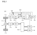
FIG. 1 presents a control block diagram for a hybrid vehicle in which the electric power conversion system according to an embodiment of the present invention is applied; -
FIG. 2 presents an electric circuit diagram of the electric conversion system according to an embodiment of the present invention; -
FIG. 3 presents a block diagram of a discharge control circuit in the power conversion system according to an embodiment of the present invention; -
FIG. 4 presents a circuit diagram showing a first exemplary embodiment of the present invention; -
FIG. 5 presents a circuit diagram showing a second exemplary embodiment of the present invention; -
FIG. 6 presents a circuit diagram showing a conventional construction that has no second discharge control circuit of an embodiment according to the present invention; -
FIG. 7 presents timing charts of various signals when a normal discharging is carried out in an embodiment of the present invention; -
FIG. 8 presents timing charts of various signals when the contactor is out of order in an embodiment of the present invention; -
FIG. 9 presents timing charts of various signals when the first discharge control circuit is out of order in an embodiment of the present invention; and -
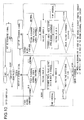
FIG. 10 presents a flowchart of discharge operation in an embodiment of the present invention. - Hereafter, the electric power conversion system according to an embodiment of the present invention will be described in detail with reference to the attached drawings. The electric power conversion system according to an embodiment of the present invention is applicable to hybrid vehicles and pure electric vehicles. Control construction and circuitry of the electric power conversion system in case of a power conversion system according to an embodiment of the present invention is applied to a hybrid automobile are explained with reference to
FIGs. 1 and2 .FIG. 1 presents a block diagram for controlling of a hybrid vehicle. - The electric power conversion system according to one embodiment of the present invention is explained by taking an example of an electric power conversion system equipped to an automobile, in particular an inverter device for an electrical machinery system that is equipped to an automobile, and in particular one that is used for an electrical machinery system for driving a vehicle in very severe environments of equipment and operation. An inverter for driving a vehicle on the one hand, which is provided in an electrical machinery system for driving a vehicle as a controller that controls driving of a motor for driving the vehicle, converts DC power supplied from an onboard battery or an onboard electricity generation device into predetermined AC power, and supplies this AC power to an AC electric motor for driving the vehicle. On the other hand, the motor for driving a vehicle has a function of an electricity generator and performs the inverse conversion of AC power generated by the AC electric motor for driving the vehicle into DC power. The converted DC power is supplied to the on-board battery.
- The construction of the present embodiment is most suitable as an electric power conversion system for driving a vehicle such as an automobile, a truck or the like.
- Referring to
Fig. 1 , a hybrid electric vehicle 110 (hereinafter termed a "HEV") is a kind of electrically powered vehicle that is equipped with two vehicle drive systems. One of these is an engine system that utilizes an internal combustion engine (ENG) 120 as a drive source. This engine system is principally used as a source of drive power for the HEV 110. The other drive system is an in-vehicle electrical machine system that utilizes motor-generators 192 and 194 (MG1 and MG2) as sources of drive force. The in-vehicle electrical machine system is principally used as a source of drive force for theHEV 110 and as a power generation source for theHEV 110. The motor-generators -
Front wheel shafts 114 are rotatably supported at the front portion of the body of the vehicle, and a pair offront wheels 112 is provided upon the ends of thesefront wheel shafts 114. Moreover, a pair of rear wheel shafts (not shown) is rotatably supported at the rear portion of the vehicle body, and a pair of rear wheels (also not shown) is provided upon the ends of these rear wheel shafts. While, with the HEV 110 of this embodiment, the so-called front wheel drive configuration is employed in which the main wheels that are powered by drive force are thefront wheels 112, and the trailing wheels that free-wheel are the rear wheels (not shown), the present invention could also be applied to the reverse configuration, i.e. to a HEV that employs the rear wheel drive configuration. - A front wheel side differential gear system 116 (hereinafter termed the "front wheel differential (DEF)") is provided at the central portion between the two
front wheel shafts 114. Thefront wheel shafts 114 are mechanically connected to the output sides of thisfront wheel differential 116. Furthermore, the output shaft of atransmission 118 is mechanically connected to the input side of thefront wheel differential 116. The front wheel differential (DEF) 116 is a differential type drive force distribution mechanism that distributes the rotational drive force that is transmitted and speed-changed through thetransmission 118 to the left and rightfront wheel shafts 114. The output side of the motor-generator 192 is mechanically connected to the input side of thetransmission 118. Furthermore, the output side of theengine 120 and the output side of the motor-generator 194 are mechanically connected to the input side of the motor-generator 192 via a driveforce distribution mechanism 122. It should be understood that the motor-generators force distribution mechanism 122 are stored in the interior of the casing 119 of thespeed change mechanism 118. - The motor-
generators inverter devices 140 and 142 (INV1 and INV2), and thereby drive control of the motor-generators inverter devices battery 136 and theinverter devices - The
HEV 110 of this first embodiment includes two motor-generator units, i.e. a first motor-generator unit that includes the motor-generator 192 and theinverter device 140, and a second motor-generator unit that includes the motor-generator 194 and theinverter device 142; and selection between these units is done according to the vehicle driving status. In other words, when the vehicle is being driven by the drive force from theengine 120, if the drive torque of the vehicle is to be assisted, the second motor-generator unit is operated as an electricity generation unit by the drive force from theengine 120, while the first motor-generator unit is operated as an electrically driven unit using the power that is generated in this way. Moreover, in a similar way, when the speed of the vehicle is to be assisted, the first motor-generator unit is operated as an electricity generation unit by the rotational force from theengine 120, while the second motor-generator unit is operated as an electrically driven unit using the power that is generated in this way. - Furthermore, with the HEV of this first embodiment, it is possible to operate the first electric drive/generator unit as an electrical drive unit using the power of the
battery 136, so as to drive the vehicle only with the drive force of the motor-generator 192. Yet further, with the HEV of this first embodiment, it is possible to operate the first electric drive/generator unit or the second electric drive/generator unit as an electricity generation unit with the drive power from theengine 120, or with drive power from the vehicle wheels, so as to charge up thebattery 136. - The
battery 136 is also used as a power supply for drivingauxiliary machinery motor 195. In such auxiliary machinery there may be incorporated, for example, a motor that drives a compressor for an air conditioner, or a motor that drives a hydraulic pump for control; DC power is supplied from thebattery 136 to aninverter device 43, and is converted into AC power by theinverter device 43 and supplied to themotor 195. This auxiliarymachinery inverter device 43 is endowed with a function similar to that of theinverter devices motor 195. For example, themotor 195 generates torque due to AC power having a leading phase with respect to the rotation of the rotor of themotor 195 being supplied. Conversely, by AC power having a delayed phase being generated, themotor 195 operates as a generator, so that themotor 195 performs regenerative braking operation. The control function of this type for theinverter device 43 is the same as the control functions for theinverter devices inverter device 43 is smaller than those of theinverter devices motor 195 is smaller than the capacities of the motor-generators inverter device 43 is fundamentally the same as the circuit structures of theinverter devices - The
inverter devices inverter device 43 as well as acapacitor module 500 are in close electrical relationship with each other. Moreover these all have the common characteristic in regard to that they need countermeasures against generation of heat. Furthermore, it is desirable to make the volumes of the inverter devices as small as possible. From these points of view, in the power conversion device that is described in detail hereinafter, theinverter devices inverter device 43, and thecapacitor module 500 are housed within the chassis of the power conversion device. With this type of structure, it is possible to implement a device that is compact and whose reliability is high. - Furthermore, by housing the
inverter devices inverter device 43, and thecapacitor module 500 within a single chassis, the beneficial effects are obtained that it is possible to simplify the wiring and to implement countermeasures against noise. Yet further, it is possible to reduce the inductances of the connection circuitry between thecapacitor module 500 and theinverter devices inverter device 43, and due to this not only is it possible to prevent the generation of spike voltage, but also it is possible to anticipate the reduction of heat generation and the enhancement of heat dissipation efficiency. The circuit structure of theinverter devices inverter device 43 will be explained with reference toFIG. 2 . Explanation is made taking examples in which the circuit structure of theinverter devices inverter device 43 are separately constructed. Since each of theinverter devices inverter device 140 will be explained as a representative. - A
power conversion device 200 includes theinverter device 140 and thecapacitor module 500, and theinverter device 140 includes aninverter circuit 144 and acontrol unit 170. And theinverter circuit 144 comprises a plurality ofcircuits 150 each including an in-series connected upper arm and lower arm (in the example shown inFig. 2 , threecircuits 150 of in-series connected upper arm and lower arm), with each of these upper arm including an IGBT (Insulated Gate type Bipolar Transistor) 328 and adiode 156 and operating as an upper arm, and each of these lower arm including an IGBT (Insulated Gate type Bipolar Transistor) 330 and adiode 166 and operating as a lower arm; and the midway point of each of the upper and lowerarm series circuits 150, i.e. theintermediate electrode 169, is connected via anAC terminal 159 to an AC power line (i.e. an AC bus bar) 186, thus being connected via theAC power line 186 to the motor-generator 192. Thecontrol unit 170 includes adriver circuit 174 that controls the operation of theinverter circuit 144, and acontrol circuit 172 that supplies a control signal to thedriver circuit 174 via asignal line 176. - The
IGBTs 328 and 330 in the upper and lower arms are semiconductor elements for power switching, and are operated by drive signals from thecontrol unit 170 so as to convert DC power supplied from thebattery 136 into three phase AC power. This power that has been converted is supplied to the armature windings of the motor-generator 192. - The
inverter circuit 144 is built as a three phase bridge circuit in which the upper and lowerarm series circuits 150 for each of three phases are electrically connected in parallel between a DCpositive terminal 314 and a DCnegative terminal 316, and the DCpositive terminal 314 and the DCnegative terminal 316 are respectively connected to the positive electrode side and the negative electrode side of thebattery 136. - The present embodiment exemplifies usage of the
IGBTs 328 and 330 as power semiconductors for switching. TheIGBTs 328 and 330 haverespective collector electrodes emitter electrode terminals gate electrode terminals 154 and 164).Diodes collector electrode IGBTs 328 and 330 and their emitter electrodes, as shown in the figure. Each of thediodes IGBTs 328 and 330 while their anode electrodes are electrically connected to the emitter electrodes of theIGBTs 328 and 330, so that the forward directions of thediodes IGBTs 328 and 330 towards their collector electrode sides. While, in this first embodiment, an example is shown in which theIGBTs 328 and 330 are used as the semiconductor elements for power switching, it would also be acceptable to use MOSFETs (Metallic Oxide Semiconductor type Field Effect Transistors) as these switching elements for power switching. In such a case, thediodes - The upper and lower
arm series circuits 150 are provided for each of three phases, corresponding to each of the three phase armature windings of the motor-generator 192. The three upper arm and the three lowerarm series circuits 150 are connected respectively to the U-phase, the V-phase, or the W-phase of themotor generator 192, respectively viaAC terminals 159 from intermediate electrode 169s, to which the emitter electrodes of the IGBTs (in the case of upper arm IGBTs 328) or thecollector electrodes 163 of the IGBTs (in the case of lower arm IGBTs 330) are connected. The upper and lowerarm series circuits 150 are connected in parallel. Thecollector electrodes 153 of theupper arm IGBTs 328 are each electrically connected (i.e. are connected via the DC bus bars) to the positive electrodeside capacitor electrode 506 of thecapacitor module 500 via the positive terminals 157 (i.e. the P terminals), while the emitter electrodes of the lower arm IGBTs 330 are each electrically connected to the negative electrodeside capacitor electrode 504 of thecapacitor module 500 via the negative terminals 158 (i.e. the N terminals). Theintermediate electrodes 169 at the connection portions between the emitter electrodes of theupper arm IGBTs 328 and the collector electrodes of the lower arm IGBTs 330 are electrically connected to the armature windings of the motor-generator 192 of the corresponding phases via anAC connector 188. - The
capacitor module 500 acts as a smoothing circuit for suppressing fluctuations of the DC voltage generated by the switching operation of theIGBTs 328 and 330. ViaDC connectors 138, the positive electrode side of thebattery 136 is connected to the positive electrodeside capacitor electrode 506 of thecapacitor module 500, while the negative electrode side of thebattery 136 is connected to the negative electrodeside capacitor electrode 504 of thecapacitor module 500. Due to this, thecapacitor module 500 is connected to the line between thecollector electrodes 153 of theupper arm IGBTs 328 and the positive electrode side of thebattery 136, and to the line between the emitter electrodes of the lower arm IGBTs 330 and the negative electrode side of thebattery 136, and thus is electrically in parallel connected to thebattery 136 and the upper and lowerarm series circuits 150. - The
control unit 170 is a circuit for operating theIGBTs 328 and 330, and includes acontrol circuit 172 that generates timing signals for controlling the timings of switching of theIGBTs 328 and 330 on the basis of information that is inputted from other control devices or sensors or the like, and adriver circuit 174 that generates a drive signal for causing the switching operations of theIGBTs 328 and 330 on the basis of these timing signals outputted from thecontrol circuit 172. - The
control circuit 172 includes a microcomputer (not shown in the figures) for performing processing for calculating the switching timings for theIGBTs 328 and 330. As input information, a target torque value that is requested for the motor-generator 192, values of currents being supplied to the armature windings of the motor-generator 192 from the upper and lowerarm series circuits 150, and the position of the magnetic poles of the rotor of the motor-generator 192, are inputted to this microcomputer. The target torque value is a value based upon a command signal outputted from a higher level control device not shown in the figures, and the current values are values that are determined on the basis of a detection signal outputted from acurrent sensor 180. Moreover, the magnetic pole position is a value that is determined on the basis of a detection signal outputted from a rotating magnetic pole sensor not shown in the figures that is provided to the motor-generator 192.While in this first embodiment an example is described in which the AC current value for each of the three phases is detected, it would also be acceptable to arrange only to detect AC current values for two of the phases. - The microcomputer (not shown) incorporated in the
control circuit 172 calculates current command values for the d-q axes of the motor-generator 192 on the basis of the target torque value, then calculates voltage command values for the d-q axes on the basis of the differences between the current command values for the d-q axes that are the result of the above calculation and the current values for the d-q axes that have been detected, and then converts these voltage command values for the d-q axis to voltage command values for the U-phase, the V-phase, and the W-phase on the basis of the magnetic pole position that has been detected. And modulated pulsed waves are generated by comparing together fundamental waves (sine waves) based upon these voltage command values for the U phase, the V phase, and the W phase and carrier waves (triangular waves), and these modulated pulsed waves are outputted to thedriver circuit 174 as PWM (Pulse Width Modulation) signals. - When driving the lower arm, the
driver circuit 174 amplifies the PWM signal described above and outputs it as a drive signal to the gate electrode of the corresponding IGBT 330 of the lower arm. Furthermore, when driving the upper arm, it amplifies the PWM signal after having shifted the level of the reference potential of the PWM signal to the level of the reference potential of the upper arm, and outputs it as a drive signal to the gate electrode of thecorresponding IGBT 328 of the upper arm. Due to this, each of theIGBTs 328 and 330 performs switching operation on the basis of the drive signal that is inputted. - The
control unit 170 performs detection of anomalies such as excess current, excess voltage, excess temperature and so on, and thereby protects the upper and lowerarm series circuits 150. For this purpose, sensing information is inputted to thecontrol unit 170. For example, information about the current that flows in the emitter electrode of each of theIGBTs 328 and 330 is inputted from theemitter electrode terminals corresponding IGBT 328 or 330, thus protecting the correspondingIGBT 328 or 330 from excessive current. Furthermore, information about the temperatures of the upper and lowerarm series circuits 150 is inputted to the microcomputer from temperature sensors (not shown in the figures) that are provided to the upper and lowerarm series circuits 150. Yet further, information about the voltage at the DC positive electrode side of the upper and lowerarm series circuits 150 is inputted to the microcomputer. The microcomputer performs excess temperature detection and excess voltage detection on the basis of such information, and, if it detects excess temperature or excess voltage, stops the switching operation of all of theIGBTs 328 and 330, thus protecting the upper and lowerarm series circuits 150, and also the semiconductor modules that includes thesecircuits 150, from excess temperature and excess voltage. - The operation of the
IGBTs 328 and 330 of the upper and lower arms of theinverter circuit 144 is changed over in a fixed order, and the current in the fixed windings of the motor-generator 192 during this changeover flows in the circuits constituted by thediodes - As shown in the figure, the upper and lower
arm series circuits 150 have: positive terminals (P terminals) 157, negative terminals (N terminals) 158,AC terminals 159 from the upper and lower armintermediate electrodes 169, upper arm signal terminals (emitter electrode terminals for monitoring) 155, upper armgate electrode terminals 154, lower arm signal terminals (emitter electrode terminals for monitoring) 165, and lower armgate electrode terminals 164. Furthermore, thepower conversion device 200 has theDC connector 138 at its input side and theAC connector 188 at its output side, and is connected to thebattery 136 and the motor-generator 192 via theconnectors -
FIG. 3 presents a block diagram showing the construction of the discharge circuit according to one embodiment of the present invention. InFig. 3 , the same reference symbols are affixed to elements that are the same as elements shown inFigs. 1 and2 , and the explanation will concentrate upon specific aspects that are different from theFigs. 1 and2 . Thebattery 136 is connected to thecapacitor module 500 for smoothing voltage provided in the inverter circuit in parallel and thebattery 136 and thecapacitor module 500 are connected via acontactor 451 provided in series therebetween to supply voltage to the inverter circuit. The ON/OFF-operation of thecontactor 451 is controlled by anupper controller 454 such as an engine controller or a battery controller. For example, in an HEV, thecontactor 451 is operated in response to a contactor ON/OFF signal from theupper controller 454 in association with start/stop-operation of the engine. - A first
discharge control circuit 470 includes a microcomputer and detects a voltage value across both ends of thecapacitor module 500 from thevoltage detection circuit 460 and an active discharge signal, which is a signal that enables discharge, from theupper controller 454 and generates a first discharge signal (A_DCHG). - The
voltage detection circuit 460 includes a plurality of resistors connected in series. Thevoltage detection circuit 460 divides the voltage between both terminals of thecapacitor module 500 and outputs the divided voltage to the firstdischarge control circuit 470. The first discharge signal (A_DCHG) output from the firstdischarge control circuit 470 is input to the seconddischarge control circuit 480 via aninsulated transmission element 453a. - The second
discharge control circuit 480 includes a microcomputer and a one-shot circuit and generates a second discharge signal (DCHG_FET) based on the first discharge signal (A_DCHG). As mentioned above, the first discharge signal (A_DCHG) can be treated as a discharge signal that is hardly influenced by noises by being regenerated as a second discharge signal (DCHG_FET) through the second discharge control circuit. The second discharge signal (DCHG_FET) is a signal that controls conduction of aswitching element 452 for discharge connected with thedischarge resistor 450 in series. When theswitching element 452 for discharging is conducted based on this signal, thecapacitor module 500 and thedischarge resistor 450 are electrically connected to each other. Charges accumulated in thecapacitor module 500 are converted into thermal energy by thedischarge resistor 450 connected in parallel to thecapacitor module 500. - Between the drain and source of the switching element 452 (between the collector and the emitter in the case of a transistor) for discharging, there is provided a
voltage detection circuit 490 that detects a voltage across both ends of theswitching element 452 for discharging. The voltage across both the ends of theswitching element 452 for discharging is output to the firstdischarge control circuit 470 via theinsulated transmission element 453b. In the firstdischarge control circuit 470, this voltage value is detected by a microcomputer equipped in the circuit and whether the switchingelement 452 for discharge operates normally or whether the discharging is carried out without fail is determined. -
LED 458 informs whether charges are stored in thecapacitor module 500. TheLED 458 connected in parallel to thecapacitor module 500 is turned ON when thecapacitor module 500 is charged to inform a maintenance operator of the possibility of electric shock. On the other hand, when the discharging of thecapacitor module 500 has been completed, theLED 458 is turned OFF. Therefore, the power conversion system is provided with a means with which the state of charge/discharge of thecapacitor module 500 can be confirmed by confirming the ON/OFF state of the LED. - The
LED 458 is to prevent electric shock when the maintenance operator touches thepower conversion system 200, so that theLED 458 should be provided at a position where the ON/OFF state of theLED 458 can be visually monitored. Therefore, theLED 458 should be provided on the surface of thepower conversion system 200. It is desirable that theLED 458 is provided, in particular, in the vicinity of a DC currentpositive terminal 314 or aDC connector 138 where electric shock occurs most likely in thepower conversion system 200. - The microcomputer provided in the first discharge control circuit outputs to the
upper controller 454 the discharge state of thecapacitor module 500, for example, as to whether charges remain in thecapacitor module 500 or the capacitor module is completely discharged, or whether the switchingelement 452 for discharge is conducting and during discharging from the voltage value between the terminals of thecapacitor module 500 and the voltage value of theswitching element 452 for discharging. - The discharge state of the
capacitor module 500, of which information is obtained from the first discharge control circuit via CAN or the like, is informed to the maintenance operator by theupper controller 454 on a display of an HEV instrument panel, or the discharge state of thecapacitor module 500 is indicated by utilizing turning ON of an LED provided on the power conversion system or peripheral circuits thereof. -
FIG. 4 shows a circuitry according to a first embodiment of the present invention. - In
FIG. 4 , the firstdischarge control circuit 470 includes afirst microcomputer 455 and detects and generates a first discharge command signal (A_DCHG) based on the voltage between both terminals of thecapacitor module 500 detected by thevoltage detection circuit 460. The first discharge command signal (A_DCHG) is input to thesecond microcomputer 456 provided in the seconddischarge control circuit 480 through theinsulated transmission element 453a such as a photocoupler. - The
second microcomputer 456 generates a second discharge command signal (DCHG_FET) based on a rising edge or a falling edge of the first discharge signal (A_DCHG). According to the method of generating a discharge signal as mentioned above, when thefirst microcomputer 455 is in failure or erroneously operates at the time of, for example, the contactor welding, a second discharge command signal (DCHG_FET) is output from thesecond microcomputer 456 based on the rising edge or falling edge of the first discharge command signal (A_DCHG) even though the first discharge command signal (A_DCHG) is affixed to H or L. Therefore, the discharge to thedischarge resistor 450 can be stopped to prevent burn out of thedischarge resistor 450. - The switching
element 452 for discharge turns to be conducting based on the second discharge command signal (DCHG_FET) and the charge stored in thecapacitor module 500 is discharged by thedischarge resistor 450 connected thereto in series. - The
voltage detection circuit 490 for switching element for discharge includes a transistor T1, a diode D1, and resistors R4, R5, and R6. When performing discharge, the switchingelement 452 for discharge is turned ON to detect the voltage across both ends of the switching element for discharging and turn the transistor T1 ON, so that theinsulated transmission element 453b connected to the transistor T1 in series is also turned ON, so that a signal of L state is input to thefirst microcomputer 455. - On the other hand, when no discharging is performed, the switching
element 452 for discharging is OFF, so that the transistor T1 and theinsulated transmission element 453b are also turned OFF. Therefore, a signal of H state obtained by pulling up to the voltage of power source of the firstdischarge control circuit 470 by means of the resistor R2 is input to thefirst microcomputer 455. It can be determined whether discharging is normally carried out based on whether the signal is H or L. - Further, the
first microcomputer 455 compares a first discharge command signal output from thefirst microcomputer 455 with a signal from thevoltage detection circuit 490 for the switching element for discharging and the result can be utilized for detecting failure of theswitching element 452 for discharging. - Further, similarly to the
first microcomputer 455, thesecond microcomputer 456 has a detection function to detect a detection voltage from thevoltage detection circuit 460 and a detection voltage from thevoltage detection circuit 490 for the switching element for discharging. With this construction, discharging can be carried out by generating an second discharge command signal (DCHG_FET) independently by thesecond microcomputer 456 alone. However, in this case, there must be adopted a circuit construction in which the circuit of the seconddischarge control circuit 480 at high voltage and the circuit of theupper controller 454 at low voltage are insulated from each other by using an insulated transmission element similar to theinsulated transmission element 453a for transmitting and receiving an active discharge signal between thesecond microcomputer 456 and theupper controller 454. -
FIG. 5 shows the circuit construction of the power conversion system according to a second embodiment of the present invention. The power conversion system according to the second embodiment corresponds to a circuit which is obtained by using a one-shot IC 457 instead of thesecond microcomputer 456 and basic circuit operations are as explained with respect to the first embodiment shown inFIG. 4 . Differences of the present embodiment from the first embodiment are explained hereafter. - The first discharge command signal (A_DCHG) output from the
first microcomputer 455 is input to the one-shot IC 457 through an insulated amplifier circuit, for example, theinsulated transmission element 453a. In the one-shot IC 457, a second discharge command signal (DCHG_FET) having a predetermined pulse width is generated based the rising edge or falling edge of the input signal. According to the method of generating a discharge signal as mentioned above, when thefirst microcomputer 455 is in failure or erroneously operates at the time of, for example, welding the contactor, a second discharge command signal (DCHG_FET) is output from the one-shot IC 457 based on the rising edge or falling edge of the first discharge command signal (A_DCHG) even though the first discharge command signal (A_DCHG) is fixed to H or L. Therefore, the discharging through thedischarge resistor 450 can be stopped to prevent burn out of thedischarge resistor 450. In this case, the seconddischarge control circuit 480 can be made to have a circuit construction that is at low cost and simple while retaining the function of preventing burn out of the discharge resistor when thefirst microcomputer 455 is in failure or erroneously operating. -
FIG. 6 shows a conventional discharge circuit construction which differs from the circuit construction according to the present embodiment. The differences from the embodiments shown inFIG. 4 orFIG. 5 will be described later. -
FIG. 7(a) presents a timing chart illustrating each signal when normal operation is performed in the present embodiment. Normal discharging of the charge stored in thecapacitor module 500 is performed in a state in which thecontactor 451 is turned OPEN and discontinuous from thebattery 136 connected in parallel thereto. - The first
discharge control circuit 470 receives active discharge signal ON from theupper controller 454 and outputs a check pulse for a certain period as the first discharge command signal (A_DCHG). The firstdischarge control circuit 470 detects the voltage between both terminals of thecapacitor module 500 at that point in time (A) by thevoltage detection circuit 460 and stores the voltage value between both terminals of thecapacitor module 500. The check pulse of the first discharge command signal (A_DCHG) output form the firstdischarge control circuit 470 is input to the seconddischarge control circuit 480 via theinsulated transmission element 453a. - The second
discharge control circuit 480 generates a second discharge command signal (DCHG_FET) by thesecond microcomputer 456 or the one-shot IC 457 based on the input first discharge command signal (A_DCHG). The charge stored in thecapacitor module 500 is discharged when the switchingelement 452 for discharge is turned conducting based on the second discharge command signal (DCHG_FET) output from the seconddischarge control circuit 480 to connect thedischarge resistor 450 in series to theswitching element 452 for discharge. After discharging (preliminary discharging) is carried out only for a check pulse period, for a predetermined period, the voltage between both terminals of thecapacitor module 500 is detected by avoltage detection circuit 460 immediately after output of the check pulse (B). - The
first microcomputer 455 provided in the firstdischarge control circuit 470 calculates a difference between a detected voltage value at time (A) and a detected voltage value at time (B) to obtain a voltage difference ΔV of (A) - (B), and when the voltage difference ΔV is greater than the predetermined voltage drop value (ΔV>ΔVsh), it is determined that the contactor is OPEN and main discharging is carried out. -
FIG. 8(a) presents a timing chart showing each signal in the present invention when the contactor is abnormal. Similarly to the normal discharging shown inFIG. 7(a) , discharging with check pulse is carried out. Thefirst microcomputer 455 equipped in the firstdischarge control circuit 470 compares the voltage difference ΔV with the predetermined voltage drop value ΔVsh. When comparison calculation results in ΔV<ΔVsh, for example in a case when thecontactor 451 is welded, it is determined that thecontactor 451 is in a CLOSE state, and the main discharging is not carried out. Therefore, discharging when thecontactor 451 is welded can be prevented from carrying out. - The timing charts shown in
FIG. 7(b) andFIG. 8(b) correspond to examples when the first discharge command signal (A_DCHG) and the second discharge command signal (DCHG_FET) are generated in the form of pulses having short duties. By using a microcomputer in the firstdischarge control circuit 470 or the second discharge control circuit, the pulse widths of the first discharge command signal (A_DCHG) and the second discharge command signal (DCHG_FET) can be freely varied by setting parameters on related software in the microcomputer. As a result, each discharge command signal can be output in the form of a pulse having a short duty, so that discharged power per pulse of discharge command signal can be decreased. That is, heat generation of thedischarge resistor 450 can be suppressed by carrying out discharging little by little with discharge command signals in the form of pulses having short duty durations. Therefore, if it is not necessary to take care of discharging time length, it is possible to use adischarge resistor 450 having a small rated power and a small volume by repeating stepwise short discharging together with suppressing heat generation of thedischarge resistor 450 as much as possible, so that the power conversion system can be down-sized. -
FIGS. 9(a) and 9(b) respectively present a timing chart illustrating each signal in the conventional circuit that is not equipped with the circuit according to the present embodiment when the first discharge control circuit is in an abnormal state, and a timing chart illustrating each signal in a circuit that is equipped with the circuit according to the present invention for comparison. For example,FIGs. 9(a) and 9(b) relate to a situation where thecontactor 451 is in a CLOSE state and the active discharge signal from theupper controller 454 is OFF, and the first discharge command signal (A_DCHG) is fixed to H or L by a failure or erroneous operation of thefirst microcomputer 455. - In the conventional circuit, the first discharge command signal (A_DCHG) is inverted to form as such the second discharge command signal (DCHG_FET) and hence it is possible that when the first discharge command signal (A_DCHG) is always ON as the active discharge signal, discharging is performed even when the contactor is in a CLOSE state, resulting in burn out of the
discharge resistor 450. - On the other hand, in the discharge circuit in the power conversion system according to the present embodiment, the second discharge command signal (DCHG_FET) is generated by an edge of the first discharge command signal (A_DCHG). As a result, even when the first discharge command signal (A_DCHG) is output always in a state of ON, due to failure or erroneous operation of the
first microcomputer 455, the output second discharge command signal (DCHG_FET) is a discharge command pulse having a short duration, so that the burn out of thedischarge resistor 450 can be prevented. - Further, similarly to the
first microcomputer 455, thesecond microcomputer 456 has a function of monitoring a detected voltage from thevoltage detection circuit 460 and a detected voltage from thevoltage detection circuit 490 for the switching element for discharging, so that thesecond microcomputer 456 by itself can independently generate a second discharge command signal (DCHG_FET) to carry out discharging. - In this case, however, it is necessary as mentioned above to use an insulated transmission element similar to the
insulated transmission element 453a to insulate the seconddischarge control circuit 480 at a high voltage and the circuit of theupper controller 454 at a low voltage from each other in transmitting and receiving active discharge signal between thesecond microcomputer 456 and theupper controller 454. -
FIG. 10 presents a flowchart illustrating discharge operation in the present embodiment. Theupper controller 454 controls an switch command signal to switch thecontactor 451 to the firstdischarge control circuit 470 or the seconddischarge control circuit 480 and the active discharge signal of theswitching element 452 for discharging. When discharging is carried out, theupper controller 454 controls thecontactor 451 to be in an OPEN state, and then outputs an active discharge signal to the firstdischarge control circuit 470. However, when thecontactor 451 is in a CLOSE state, no active discharge signal is output and is OFF, so that the discharge operation flow returns to START. - The first
discharge control circuit 470 performs checking operation of its own circuit based on the input active discharge signal. When it is determined that the operation of the firstdischarge control circuit 470 is normal, voltage check A is performed by thevoltage detection circuit 460 to detect a voltage between both terminals of thecapacitor module 500 at time A and stores the detected voltage value. On the other hand, when it is determined that the operation of the firstdischarge control circuit 470 is abnormal, the firstdischarge control circuit 470 transmits an abnormal determination signal to theupper controller 454. - When the first
discharge control circuit 470 is determined to be in an abnormal state, if the seconddischarge control circuit 480 includes asecond microcomputer 456 in the circuitry, the active discharge signal from theupper controller 454 is output to the seconddischarge control circuit 480. In the construction in which the seconddischarge control circuit 480 includes one-shot IC 457 or the like, it outputs only an abnormality determination signal to theupper controller 454 and its operation circulates in a determination loop for determining OPEN/CLOSE of the contactor. - After the first
discharge control circuit 470 is determined to be normal and the voltage check A is performed, the firstdischarge control circuit 470 outputs a discharge check pulse to perform preliminary discharge. Thefirst microcomputer 455 equipped in the firstdischarge control circuit 470 detects with the voltage detection circuit 460 a voltage between both terminals of thecapacitor module 500 at time B immediately after the preliminary discharging has been carried out. Thefirst microcomputer 455 calculates a voltage difference ΔV between voltages detected at times A and B. When the voltage difference ΔV is equal to or greater than the predetermined voltage threshold value, the main discharging is carried out. On the other hand, when the calculated voltage difference ΔV is equal to or less than the voltage threshold ΔVsh, the discharge operation flow is carried out again starting from the voltage check after a predetermined time interval elapsed. - The discharge operation flow for the second discharge control circuit, when discharging is carried out by the second
discharge control circuit 480 in a case that the first discharge circuit is in an abnormal state, is similar to the above mentioned discharge operation flow for the firstdischarge control circuit 470. After the active discharge signal is received from theupper controller 454, the voltage between both terminals of thecapacitor module 500 is detected by the voltage check A and preliminary discharging is carried out according to the discharge check pulse. After the preliminary discharging, the voltage check B is performed, and a voltage difference ΔV between the detected voltages is calculated. The calculated voltage difference ΔV is compared with the voltage threshold value ΔVsh, and main discharging is performed. - According to the present embodiment, there can be provided an inverter control device that can prevent the burn out of the discharge resistor due to failure of the discharge control circuit or due to erroneous discharge signal in a state where the contactor is closed and enables improvement of reliability. Since the discharge signal is variable, discharging time can be adjusted. In addition, if it is not necessary to take care of discharging time length, discharge resistors having low rating can be used, so that a down-sized inverter control device can be provided.
- Although various embodiments and variations have been explained above, the present invention is not limited thereto. Other embodiments and variations that are conceivable within the range of technical concept of the present invention are also included in the scope of the present invention.
- The disclosure of the following priority application is herein incorporated by reference: Japanese Patent Application No.
2009-048718 filed March 3, 2009
Claims (13)
- A power conversion system comprising:an inverter circuit unit that converts a direct current power supplied from a direct current source into an alternating current power, the direct current power being supplied to the inverter circuit through a contactor that conducts and interrupts the direct current;a capacitor that smoothes the direct current power;a discharge circuit unit that is connected to the capacitor in parallel, and that includes a discharge resistor for discharging a charge stored in the capacitor and a switching element for the discharge resistor, being connected in series to the discharge resistor;a voltage detection circuit unit that detects voltage between both terminals of the capacitor;a first discharge control circuit that includes a first microcomputer, and that outputs a control signal to control switching of the switching element for discharging; anda second discharge control circuit that outputs an interruption signal to interrupt the switching element for the discharge resistor.
- A power conversion system according to claim 1, wherein
the first discharge control circuit outputs the control signal to controls switching of the switching element for discharging, based on a voltage value detected by the voltage detection circuit unit and on a switch signal for the contactor output from an external upper controller. - A power conversion system according to claim 1, wherein
the first discharge control circuit receives a discharge signal to start discharging output from an external upper controller, and outputs the control signal to control switching of the switching element for discharging, based on the discharge signal and the voltage value. - A power conversion system according to claim 1, wherein
the first discharge control circuit outputs the control signal to control switching of the switching element for discharging based on the discharge signal detected by the voltage detection circuit unit and a discharge signal to start discharging output from an external upper controller, and
the second discharge control circuit outputs, based on the control signal, a conduction command signal to achieve conduction of the switching element for the discharge resistor for a predetermined period and an interruption command signal to interrupt the switching element for the discharge resistor after the conduction for the predetermined period. - A power conversion system according to any one of claims 1 to 4, wherein
the control signal output by the first discharge control circuit is a control signal that has a rising edge and a falling edge, and
the second discharge control circuit outputs the conduction command signal or the interruption command signal corresponding to the rising edge and the falling edge, respectively. - A power conversion system according to any one of claims 1 to 4, wherein
the control signal output by the first discharge control circuit is a control signal that has a high level signal and a low level signal, and
the second discharge control circuit outputs the conduction command signal or the interruption command signal corresponding to the high level signal and the low level signal, respectively. - A power conversion system according to claim 1, wherein
the first discharge control circuit and the second discharge control circuit are insulated from each other with an insulated transmission element. - A power conversion system according to claim 1, wherein
the second discharge control circuit includes a circuit equipped with a second microcomputer. - A power conversion system according to claim 1, wherein
the second discharge control circuit includes a circuit equipped with a one-shot circuit. - A power conversion system according to claim 7 or 8, wherein
the second discharge control circuit controls a pulse width of the control signal generated by the first discharge control circuit and a pulse width of a second control signal generated by the second discharge control circuit. - A power conversion system according to claim 1, further comprising:an informing circuit that is connected to the capacitor in parallel and that informs whether charges stored in the capacitor have been discharged.
- A power conversion system according to claim 10, further comprising:a direct current source terminal that is supplied with direct current power from the direct current source and supplies the direct current power to the inverter circuit unit; andan alternating current output terminal that is supplied with the alternating current power from the inverter circuit unit, whereinthe informing circuit includes a light emitting device and arranged on a side that is closer to the direct current source terminal than the alternating current output terminal.
- A discharge control device comprising:a discharge resistor that is electrically connected to a capacitor that smoothes current or voltage input to an inverter circuit unit;a discharge circuit unit including a switching circuit connected to the discharge resistor in series;a microcomputer that outputs a first pulse to control whether a charge stored in the capacitor is discharged to the discharge circuit unit; anda pulse generation circuit unit that generates a second pulse having a predetermined pulse width based on rising or falling or both of the first pulse, whereinthe switching circuit is controlled such that discharging of the charge stored in the capacitor to the discharge resistor is stopped based on output of the second pulse.
Applications Claiming Priority (2)
| Application Number | Priority Date | Filing Date | Title |
|---|---|---|---|
| JP2009048718A JP5244653B2 (en) | 2009-03-03 | 2009-03-03 | Power converter |
| PCT/JP2010/052548 WO2010101032A1 (en) | 2009-03-03 | 2010-02-19 | Power converter |
Publications (3)
| Publication Number | Publication Date |
|---|---|
| EP2405565A1 true EP2405565A1 (en) | 2012-01-11 |
| EP2405565A4 EP2405565A4 (en) | 2013-07-24 |
| EP2405565B1 EP2405565B1 (en) | 2017-11-15 |
Family
ID=42709593
Family Applications (1)
| Application Number | Title | Priority Date | Filing Date |
|---|---|---|---|
| EP10748628.4A Active EP2405565B1 (en) | 2009-03-03 | 2010-02-19 | Power converter |
Country Status (5)
| Country | Link |
|---|---|
| US (1) | US8791681B2 (en) |
| EP (1) | EP2405565B1 (en) |
| JP (1) | JP5244653B2 (en) |
| CN (1) | CN102326327B (en) |
| WO (1) | WO2010101032A1 (en) |
Cited By (10)
| Publication number | Priority date | Publication date | Assignee | Title |
|---|---|---|---|---|
| FR2990310A1 (en) * | 2012-05-04 | 2013-11-08 | Schneider Electric Ind Sas | Electric conversion stage for electric converter of electric battery recharging terminal of car, has capacitor connected between output terminals, and electromagnetic coil connected between one of terminals and midpoint of switching branch |
| WO2013189875A1 (en) * | 2012-06-22 | 2013-12-27 | Robert Bosch Gmbh | Battery comprising at least one semiconductor-based separating device |
| FR2998115A1 (en) * | 2012-11-13 | 2014-05-16 | Schneider Electric Ind Sas | Electric conversion stage for electric converter of electric battery recharging terminal of car, has capacitor connected between output terminals, and electromagnetic coil connected between one of terminals and midpoint of switching branch |
| WO2013143770A3 (en) * | 2012-03-27 | 2014-06-19 | Robert Bosch Gmbh | Safety device for a high-voltage system and method for safeguarding a high-voltage system |
| EP2860059A3 (en) * | 2013-10-04 | 2015-12-09 | Samsung SDI Co., Ltd. | Electric vehicle power conversion system |
| US9270182B2 (en) | 2012-05-04 | 2016-02-23 | Schneider Electric Industries Sas | Conversion stage, electric converter including such a conversion stage, device for converting an AC current into DC current including such a converter, terminal for recharging an electric battery including such a converter or conversion device |
| EP3034351A3 (en) * | 2014-12-01 | 2016-10-19 | Magneti Marelli S.p.A. | Electronic device for controlling the electric charge of a load electrically supplied by a battery pack and system for moving an electric or hybrid traction vehicle using the device |
| EP2670042A3 (en) * | 2012-06-02 | 2017-02-08 | SEMIKRON Elektronik GmbH & Co. KG | Power converter with redundant link circuit voltage measuring circuit, and method for operating a power converter |
| EP3588756A1 (en) * | 2018-06-29 | 2020-01-01 | Valeo Siemens eAutomotive Germany GmbH | Device and method for discharging an intermediate circuit capacitor and method for producing a device for discharging an intermediate circuit capacitor |
| WO2021008727A3 (en) * | 2019-07-18 | 2021-03-11 | Sew-Eurodrive Gmbh & Co. Kg | Method and device for operating a system comprising an energy storage device and resistor |
Families Citing this family (35)
| Publication number | Priority date | Publication date | Assignee | Title |
|---|---|---|---|---|
| JP5681210B2 (en) * | 2010-12-07 | 2015-03-04 | 日立オートモティブシステムズ株式会社 | Power converter |
| US9079482B2 (en) * | 2011-02-25 | 2015-07-14 | Deere & Company | Powered vehicle with an independent and interchangeable powertrain assembly |
| JP5623994B2 (en) * | 2011-07-29 | 2014-11-12 | 日立オートモティブシステムズ株式会社 | Power converter |
| JP5731360B2 (en) | 2011-11-18 | 2015-06-10 | 日立オートモティブシステムズ株式会社 | Power converter |
| JP5505451B2 (en) * | 2012-04-13 | 2014-05-28 | 株式会社デンソー | Power converter |
| JP5991526B2 (en) * | 2012-09-18 | 2016-09-14 | 株式会社デンソー | Switching element drive IC |
| JP2014128045A (en) * | 2012-12-25 | 2014-07-07 | Panasonic Corp | Motor drive unit and electrical apparatus including the same |
| JP5652622B2 (en) * | 2013-01-08 | 2015-01-14 | 三菱自動車工業株式会社 | Vehicle abnormality diagnosis device |
| JP2015019515A (en) * | 2013-07-11 | 2015-01-29 | アイシン・エィ・ダブリュ株式会社 | Discharge control device |
| JP6308656B2 (en) * | 2014-02-21 | 2018-04-11 | 株式会社エヌエフ回路設計ブロック | Power supply device and voltage source connection determination circuit |
| JP6479383B2 (en) * | 2014-09-22 | 2019-03-06 | 株式会社東芝 | Vehicle storage battery system |
| KR102326065B1 (en) * | 2014-10-31 | 2021-11-12 | 현대모비스 주식회사 | Apparatus for converting power of electric vehicle |
| US20170370523A1 (en) * | 2015-01-22 | 2017-12-28 | Siemens Industry, Inc. | Electrostatic oil ring, electrostatic oil ring assembly, and electrodynamic machine |
| WO2016121632A1 (en) * | 2015-01-29 | 2016-08-04 | 三菱電機株式会社 | Power conversion device |
| JP2016167929A (en) * | 2015-03-10 | 2016-09-15 | 日産自動車株式会社 | Power supply controller |
| CN108141144B (en) * | 2015-09-18 | 2020-10-23 | 株式会社安川电机 | Inverter device and method for manufacturing inverter device |
| WO2017046964A1 (en) * | 2015-09-18 | 2017-03-23 | 株式会社安川電機 | Inverter device and method for controlling inverter device |
| CN105717835A (en) * | 2016-02-01 | 2016-06-29 | 珠海格力电器股份有限公司 | Electric appliance and mainboard discharge control method and device |
| JP6696308B2 (en) * | 2016-06-09 | 2020-05-20 | 富士電機株式会社 | Switching power supply |
| KR102121639B1 (en) * | 2016-07-15 | 2020-06-10 | 주식회사 엘지화학 | System and method for perventing the abnormal opening of the contactor using real-time detection |
| JP6407477B1 (en) * | 2017-04-12 | 2018-10-17 | 三菱電機株式会社 | Synchronous control system and control device |
| DE102017208411A1 (en) * | 2017-05-18 | 2018-11-22 | Zf Friedrichshafen Ag | Limitation of overvoltages due to electrical load shedding during regenerative operation of a vehicle electrical system |
| JP6645523B2 (en) * | 2017-06-30 | 2020-02-14 | サンケン電気株式会社 | Power converter and control circuit |
| CN109217643B (en) * | 2017-06-30 | 2020-09-15 | 三垦电气株式会社 | Power conversion device and control circuit |
| JP6856502B2 (en) * | 2017-11-20 | 2021-04-07 | 本田技研工業株式会社 | Power supply system and control method of power supply system |
| JP6448825B1 (en) * | 2018-01-11 | 2019-01-09 | 三菱電機株式会社 | Charge control device |
| US10778713B2 (en) | 2018-02-26 | 2020-09-15 | International Business Machines Corporation | Method and system to manage risk of vulnerabilities and corresponding change actions to address malware threats |
| JP6939740B2 (en) * | 2018-08-24 | 2021-09-22 | 三菱電機株式会社 | Semiconductor module |
| JP7050391B2 (en) * | 2018-12-20 | 2022-04-08 | 東芝三菱電機産業システム株式会社 | Power converter |
| CN109756016B (en) * | 2019-01-15 | 2023-06-09 | 浙江大邦科技有限公司 | Rapid discharge method of super capacitor |
| JP7322493B2 (en) * | 2019-05-08 | 2023-08-08 | 富士電機株式会社 | Inverter device and inverter control program |
| JP7181416B2 (en) * | 2019-08-30 | 2022-11-30 | 日立Astemo株式会社 | Discharge control circuit and power converter |
| JP7349371B2 (en) | 2020-01-14 | 2023-09-22 | 日立Astemo株式会社 | discharge control circuit |
| JP6804703B1 (en) * | 2020-02-04 | 2020-12-23 | 三菱電機株式会社 | Power converter and power conversion system |
| JP7196870B2 (en) * | 2020-02-13 | 2022-12-27 | 株式会社デンソー | Power converter control circuit |
Citations (3)
| Publication number | Priority date | Publication date | Assignee | Title |
|---|---|---|---|---|
| JPH04127801A (en) * | 1990-09-19 | 1992-04-28 | Hitachi Ltd | Protective device of controller for electric rolling stock |
| US5619107A (en) * | 1994-07-13 | 1997-04-08 | Honda Giken Kogyo Kabushiki Kaisha | System for controlling electric vehicle motor |
| JP2000078851A (en) * | 1998-08-28 | 2000-03-14 | Nissan Motor Co Ltd | Forcible discharger for dc link capacitor |
Family Cites Families (12)
| Publication number | Priority date | Publication date | Assignee | Title |
|---|---|---|---|---|
| US5111027A (en) * | 1989-07-06 | 1992-05-05 | Robertshaw Controls Company | Control system and methods of making and operating the same |
| JPH09149508A (en) * | 1995-11-20 | 1997-06-06 | Isuzu Motors Ltd | Power supply unit for electric car |
| JP2000278802A (en) * | 1999-03-23 | 2000-10-06 | Toyota Motor Corp | Failure decision system |
| DE10134635C1 (en) * | 2001-07-17 | 2003-01-16 | Texas Instruments Deutschland | Resistance measuring circuit e.g. for heating energy meter has charged capacitance discharged via reference resistance and measuring resistance during successive cycles |
| DE10392735T5 (en) * | 2003-03-17 | 2007-03-15 | Mitsubishi Denki K.K. | inverter device |
| JP3705278B2 (en) * | 2003-06-11 | 2005-10-12 | トヨタ自動車株式会社 | Battery connection control device for electric vehicle |
| JP4418318B2 (en) | 2004-07-26 | 2010-02-17 | 株式会社日立製作所 | Power conversion device and electric vehicle using the same |
| JP2006246569A (en) * | 2005-03-01 | 2006-09-14 | Mitsubishi Motors Corp | Power control device of vehicle |
| WO2008001427A1 (en) * | 2006-06-27 | 2008-01-03 | Mitsubishi Electric Corporation | Power converter |
| JP4697180B2 (en) | 2007-04-25 | 2011-06-08 | トヨタ自動車株式会社 | Power supply control device, power supply device control method, and computer-readable recording medium storing a program for causing a computer to execute the power supply device control method |
| JP2009048718A (en) | 2007-08-21 | 2009-03-05 | Fujitsu Microelectronics Ltd | Semiconductor memory device and bus system |
| US8039993B2 (en) * | 2008-04-24 | 2011-10-18 | GM Global Technology Operations LLC | High-voltage bus discharge with logarithmic self-protection |
-
2009
- 2009-03-03 JP JP2009048718A patent/JP5244653B2/en active Active
-
2010
- 2010-02-19 EP EP10748628.4A patent/EP2405565B1/en active Active
- 2010-02-19 CN CN201080008257.1A patent/CN102326327B/en active Active
- 2010-02-19 US US13/201,139 patent/US8791681B2/en active Active
- 2010-02-19 WO PCT/JP2010/052548 patent/WO2010101032A1/en active Application Filing
Patent Citations (3)
| Publication number | Priority date | Publication date | Assignee | Title |
|---|---|---|---|---|
| JPH04127801A (en) * | 1990-09-19 | 1992-04-28 | Hitachi Ltd | Protective device of controller for electric rolling stock |
| US5619107A (en) * | 1994-07-13 | 1997-04-08 | Honda Giken Kogyo Kabushiki Kaisha | System for controlling electric vehicle motor |
| JP2000078851A (en) * | 1998-08-28 | 2000-03-14 | Nissan Motor Co Ltd | Forcible discharger for dc link capacitor |
Non-Patent Citations (1)
| Title |
|---|
| See also references of WO2010101032A1 * |
Cited By (14)
| Publication number | Priority date | Publication date | Assignee | Title |
|---|---|---|---|---|
| WO2013143770A3 (en) * | 2012-03-27 | 2014-06-19 | Robert Bosch Gmbh | Safety device for a high-voltage system and method for safeguarding a high-voltage system |
| US9590416B2 (en) | 2012-03-27 | 2017-03-07 | Robert Bosch Gmbh | Safety device for a high-voltage system and method for safeguarding a high-voltage system |
| EP2660095A3 (en) * | 2012-05-04 | 2017-11-15 | Schneider Electric Industries SAS | Converter stage, electrical converter comprising such a converter stage, ac/dc converter comprising such a converter, and battery charching terminal comprising such a converter or converter stage |
| US9270182B2 (en) | 2012-05-04 | 2016-02-23 | Schneider Electric Industries Sas | Conversion stage, electric converter including such a conversion stage, device for converting an AC current into DC current including such a converter, terminal for recharging an electric battery including such a converter or conversion device |
| FR2990310A1 (en) * | 2012-05-04 | 2013-11-08 | Schneider Electric Ind Sas | Electric conversion stage for electric converter of electric battery recharging terminal of car, has capacitor connected between output terminals, and electromagnetic coil connected between one of terminals and midpoint of switching branch |
| EP2670042A3 (en) * | 2012-06-02 | 2017-02-08 | SEMIKRON Elektronik GmbH & Co. KG | Power converter with redundant link circuit voltage measuring circuit, and method for operating a power converter |
| WO2013189875A1 (en) * | 2012-06-22 | 2013-12-27 | Robert Bosch Gmbh | Battery comprising at least one semiconductor-based separating device |
| FR2998115A1 (en) * | 2012-11-13 | 2014-05-16 | Schneider Electric Ind Sas | Electric conversion stage for electric converter of electric battery recharging terminal of car, has capacitor connected between output terminals, and electromagnetic coil connected between one of terminals and midpoint of switching branch |
| EP2860059A3 (en) * | 2013-10-04 | 2015-12-09 | Samsung SDI Co., Ltd. | Electric vehicle power conversion system |
| EP3034351A3 (en) * | 2014-12-01 | 2016-10-19 | Magneti Marelli S.p.A. | Electronic device for controlling the electric charge of a load electrically supplied by a battery pack and system for moving an electric or hybrid traction vehicle using the device |
| EP3588756A1 (en) * | 2018-06-29 | 2020-01-01 | Valeo Siemens eAutomotive Germany GmbH | Device and method for discharging an intermediate circuit capacitor and method for producing a device for discharging an intermediate circuit capacitor |
| CN110661407A (en) * | 2018-06-29 | 2020-01-07 | 法雷奥西门子新能源汽车(德国)有限公司 | Device, method and method for discharging an intermediate circuit capacitor |
| WO2021008727A3 (en) * | 2019-07-18 | 2021-03-11 | Sew-Eurodrive Gmbh & Co. Kg | Method and device for operating a system comprising an energy storage device and resistor |
| US11750139B2 (en) | 2019-07-18 | 2023-09-05 | Sew-Eurodrive Gmbh & Co. Kg | Method and system for operating a system including an energy storage device and resistor |
Also Published As
| Publication number | Publication date |
|---|---|
| EP2405565A4 (en) | 2013-07-24 |
| US8791681B2 (en) | 2014-07-29 |
| US20120020136A1 (en) | 2012-01-26 |
| JP2010206909A (en) | 2010-09-16 |
| JP5244653B2 (en) | 2013-07-24 |
| CN102326327A (en) | 2012-01-18 |
| CN102326327B (en) | 2014-06-25 |
| WO2010101032A1 (en) | 2010-09-10 |
| EP2405565B1 (en) | 2017-11-15 |
Similar Documents
| Publication | Publication Date | Title |
|---|---|---|
| US8791681B2 (en) | Electric power conversion system | |
| EP2284982B1 (en) | Discharge circuit for smoothing capacitor of DC power supply | |
| JP5731360B2 (en) | Power converter | |
| JP5315155B2 (en) | Semiconductor element control device, automotive electrical system | |
| US8547041B2 (en) | Power conversion device | |
| JP5065986B2 (en) | Semiconductor device driving apparatus and driving method thereof | |
| US20090195199A1 (en) | Motor drive device | |
| JP5648000B2 (en) | Power converter | |
| JP2013005067A (en) | Power conversion apparatus | |
| JP5303295B2 (en) | Power converter for vehicle and electric vehicle | |
| JP2010035279A (en) | Power supply system and electric vehicle | |
| CN110182150B (en) | Power supply device for vehicle | |
| JP6218169B2 (en) | Protection circuit, inverter device | |
| JP2006304542A (en) | Voltage converter | |
| JP6786463B2 (en) | Power converter | |
| JP5975797B2 (en) | Power converter | |
| JP2014183638A (en) | Power conversion device | |
| CN117526778A (en) | Method and device for operating at least one switching device of a rectifier of a trolley drive of a motor vehicle | |
| JP2005304235A (en) | Power supply device for vehicle | |
| CN115136477A (en) | Semiconductor device, power module, inverter device, and electric vehicle |
Legal Events
| Date | Code | Title | Description |
|---|---|---|---|
| PUAI | Public reference made under article 153(3) epc to a published international application that has entered the european phase |
Free format text: ORIGINAL CODE: 0009012 |
|
| 17P | Request for examination filed |
Effective date: 20111004 |
|
| AK | Designated contracting states |
Kind code of ref document: A1 Designated state(s): AT BE BG CH CY CZ DE DK EE ES FI FR GB GR HR HU IE IS IT LI LT LU LV MC MK MT NL NO PL PT RO SE SI SK SM TR |
|
| DAX | Request for extension of the european patent (deleted) | ||
| A4 | Supplementary search report drawn up and despatched |
Effective date: 20130620 |
|
| RIC1 | Information provided on ipc code assigned before grant |
Ipc: H02M 1/32 20070101ALI20130614BHEP Ipc: B60L 11/18 20060101ALI20130614BHEP Ipc: H02M 7/48 20070101AFI20130614BHEP |
|
| 17Q | First examination report despatched |
Effective date: 20140521 |
|
| GRAP | Despatch of communication of intention to grant a patent |
Free format text: ORIGINAL CODE: EPIDOSNIGR1 |
|
| INTG | Intention to grant announced |
Effective date: 20170609 |
|
| GRAS | Grant fee paid |
Free format text: ORIGINAL CODE: EPIDOSNIGR3 |
|
| GRAA | (expected) grant |
Free format text: ORIGINAL CODE: 0009210 |
|
| AK | Designated contracting states |
Kind code of ref document: B1 Designated state(s): AT BE BG CH CY CZ DE DK EE ES FI FR GB GR HR HU IE IS IT LI LT LU LV MC MK MT NL NO PL PT RO SE SI SK SM TR |
|
| REG | Reference to a national code |
Ref country code: CH Ref legal event code: EP Ref country code: GB Ref legal event code: FG4D Ref country code: AT Ref legal event code: REF Ref document number: 947196 Country of ref document: AT Kind code of ref document: T Effective date: 20171115 |
|
| RIN1 | Information on inventor provided before grant (corrected) |
Inventor name: NOTO, YASUO Inventor name: YAHATA, KOICHI Inventor name: TSUJI, MASASHIGE Inventor name: FUNABA, SEIJI Inventor name: AKAISHI, YOSHIO |
|
| REG | Reference to a national code |
Ref country code: IE Ref legal event code: FG4D |
|
| REG | Reference to a national code |
Ref country code: DE Ref legal event code: R096 Ref document number: 602010046727 Country of ref document: DE |
|
| REG | Reference to a national code |
Ref country code: NL Ref legal event code: MP Effective date: 20171115 |
|
| REG | Reference to a national code |
Ref country code: LT Ref legal event code: MG4D |
|
| REG | Reference to a national code |
Ref country code: AT Ref legal event code: MK05 Ref document number: 947196 Country of ref document: AT Kind code of ref document: T Effective date: 20171115 |
|
| PG25 | Lapsed in a contracting state [announced via postgrant information from national office to epo] |
Ref country code: LT Free format text: LAPSE BECAUSE OF FAILURE TO SUBMIT A TRANSLATION OF THE DESCRIPTION OR TO PAY THE FEE WITHIN THE PRESCRIBED TIME-LIMIT Effective date: 20171115 Ref country code: ES Free format text: LAPSE BECAUSE OF FAILURE TO SUBMIT A TRANSLATION OF THE DESCRIPTION OR TO PAY THE FEE WITHIN THE PRESCRIBED TIME-LIMIT Effective date: 20171115 Ref country code: SE Free format text: LAPSE BECAUSE OF FAILURE TO SUBMIT A TRANSLATION OF THE DESCRIPTION OR TO PAY THE FEE WITHIN THE PRESCRIBED TIME-LIMIT Effective date: 20171115 Ref country code: FI Free format text: LAPSE BECAUSE OF FAILURE TO SUBMIT A TRANSLATION OF THE DESCRIPTION OR TO PAY THE FEE WITHIN THE PRESCRIBED TIME-LIMIT Effective date: 20171115 Ref country code: NL Free format text: LAPSE BECAUSE OF FAILURE TO SUBMIT A TRANSLATION OF THE DESCRIPTION OR TO PAY THE FEE WITHIN THE PRESCRIBED TIME-LIMIT Effective date: 20171115 Ref country code: NO Free format text: LAPSE BECAUSE OF FAILURE TO SUBMIT A TRANSLATION OF THE DESCRIPTION OR TO PAY THE FEE WITHIN THE PRESCRIBED TIME-LIMIT Effective date: 20180215 |
|
| PG25 | Lapsed in a contracting state [announced via postgrant information from national office to epo] |
Ref country code: LV Free format text: LAPSE BECAUSE OF FAILURE TO SUBMIT A TRANSLATION OF THE DESCRIPTION OR TO PAY THE FEE WITHIN THE PRESCRIBED TIME-LIMIT Effective date: 20171115 Ref country code: AT Free format text: LAPSE BECAUSE OF FAILURE TO SUBMIT A TRANSLATION OF THE DESCRIPTION OR TO PAY THE FEE WITHIN THE PRESCRIBED TIME-LIMIT Effective date: 20171115 Ref country code: GR Free format text: LAPSE BECAUSE OF FAILURE TO SUBMIT A TRANSLATION OF THE DESCRIPTION OR TO PAY THE FEE WITHIN THE PRESCRIBED TIME-LIMIT Effective date: 20180216 Ref country code: HR Free format text: LAPSE BECAUSE OF FAILURE TO SUBMIT A TRANSLATION OF THE DESCRIPTION OR TO PAY THE FEE WITHIN THE PRESCRIBED TIME-LIMIT Effective date: 20171115 Ref country code: BG Free format text: LAPSE BECAUSE OF FAILURE TO SUBMIT A TRANSLATION OF THE DESCRIPTION OR TO PAY THE FEE WITHIN THE PRESCRIBED TIME-LIMIT Effective date: 20180215 |
|
| PG25 | Lapsed in a contracting state [announced via postgrant information from national office to epo] |
Ref country code: SK Free format text: LAPSE BECAUSE OF FAILURE TO SUBMIT A TRANSLATION OF THE DESCRIPTION OR TO PAY THE FEE WITHIN THE PRESCRIBED TIME-LIMIT Effective date: 20171115 Ref country code: EE Free format text: LAPSE BECAUSE OF FAILURE TO SUBMIT A TRANSLATION OF THE DESCRIPTION OR TO PAY THE FEE WITHIN THE PRESCRIBED TIME-LIMIT Effective date: 20171115 Ref country code: CY Free format text: LAPSE BECAUSE OF FAILURE TO SUBMIT A TRANSLATION OF THE DESCRIPTION OR TO PAY THE FEE WITHIN THE PRESCRIBED TIME-LIMIT Effective date: 20171115 Ref country code: DK Free format text: LAPSE BECAUSE OF FAILURE TO SUBMIT A TRANSLATION OF THE DESCRIPTION OR TO PAY THE FEE WITHIN THE PRESCRIBED TIME-LIMIT Effective date: 20171115 Ref country code: CZ Free format text: LAPSE BECAUSE OF FAILURE TO SUBMIT A TRANSLATION OF THE DESCRIPTION OR TO PAY THE FEE WITHIN THE PRESCRIBED TIME-LIMIT Effective date: 20171115 |
|
| REG | Reference to a national code |
Ref country code: DE Ref legal event code: R097 Ref document number: 602010046727 Country of ref document: DE |
|
| PG25 | Lapsed in a contracting state [announced via postgrant information from national office to epo] |
Ref country code: SM Free format text: LAPSE BECAUSE OF FAILURE TO SUBMIT A TRANSLATION OF THE DESCRIPTION OR TO PAY THE FEE WITHIN THE PRESCRIBED TIME-LIMIT Effective date: 20171115 Ref country code: PL Free format text: LAPSE BECAUSE OF FAILURE TO SUBMIT A TRANSLATION OF THE DESCRIPTION OR TO PAY THE FEE WITHIN THE PRESCRIBED TIME-LIMIT Effective date: 20171115 Ref country code: IT Free format text: LAPSE BECAUSE OF FAILURE TO SUBMIT A TRANSLATION OF THE DESCRIPTION OR TO PAY THE FEE WITHIN THE PRESCRIBED TIME-LIMIT Effective date: 20171115 Ref country code: RO Free format text: LAPSE BECAUSE OF FAILURE TO SUBMIT A TRANSLATION OF THE DESCRIPTION OR TO PAY THE FEE WITHIN THE PRESCRIBED TIME-LIMIT Effective date: 20171115 |
|
| REG | Reference to a national code |
Ref country code: CH Ref legal event code: PL |
|
| PLBE | No opposition filed within time limit |
Free format text: ORIGINAL CODE: 0009261 |
|
| STAA | Information on the status of an ep patent application or granted ep patent |
Free format text: STATUS: NO OPPOSITION FILED WITHIN TIME LIMIT |
|
| PG25 | Lapsed in a contracting state [announced via postgrant information from national office to epo] |
Ref country code: MC Free format text: LAPSE BECAUSE OF FAILURE TO SUBMIT A TRANSLATION OF THE DESCRIPTION OR TO PAY THE FEE WITHIN THE PRESCRIBED TIME-LIMIT Effective date: 20171115 |
|
| 26N | No opposition filed |
Effective date: 20180817 |
|
| GBPC | Gb: european patent ceased through non-payment of renewal fee |
Effective date: 20180219 |
|
| REG | Reference to a national code |
Ref country code: IE Ref legal event code: MM4A |
|
| REG | Reference to a national code |
Ref country code: BE Ref legal event code: MM Effective date: 20180228 |
|
| PG25 | Lapsed in a contracting state [announced via postgrant information from national office to epo] |
Ref country code: SI Free format text: LAPSE BECAUSE OF FAILURE TO SUBMIT A TRANSLATION OF THE DESCRIPTION OR TO PAY THE FEE WITHIN THE PRESCRIBED TIME-LIMIT Effective date: 20171115 Ref country code: CH Free format text: LAPSE BECAUSE OF NON-PAYMENT OF DUE FEES Effective date: 20180228 Ref country code: LU Free format text: LAPSE BECAUSE OF NON-PAYMENT OF DUE FEES Effective date: 20180219 Ref country code: LI Free format text: LAPSE BECAUSE OF NON-PAYMENT OF DUE FEES Effective date: 20180228 |
|
| REG | Reference to a national code |
Ref country code: FR Ref legal event code: ST Effective date: 20181031 |
|
| PG25 | Lapsed in a contracting state [announced via postgrant information from national office to epo] |
Ref country code: IE Free format text: LAPSE BECAUSE OF NON-PAYMENT OF DUE FEES Effective date: 20180219 |
|
| PG25 | Lapsed in a contracting state [announced via postgrant information from national office to epo] |
Ref country code: GB Free format text: LAPSE BECAUSE OF NON-PAYMENT OF DUE FEES Effective date: 20180219 Ref country code: FR Free format text: LAPSE BECAUSE OF NON-PAYMENT OF DUE FEES Effective date: 20180228 Ref country code: BE Free format text: LAPSE BECAUSE OF NON-PAYMENT OF DUE FEES Effective date: 20180228 |
|
| PG25 | Lapsed in a contracting state [announced via postgrant information from national office to epo] |
Ref country code: MT Free format text: LAPSE BECAUSE OF NON-PAYMENT OF DUE FEES Effective date: 20180219 |
|
| PG25 | Lapsed in a contracting state [announced via postgrant information from national office to epo] |
Ref country code: TR Free format text: LAPSE BECAUSE OF FAILURE TO SUBMIT A TRANSLATION OF THE DESCRIPTION OR TO PAY THE FEE WITHIN THE PRESCRIBED TIME-LIMIT Effective date: 20171115 |
|
| PG25 | Lapsed in a contracting state [announced via postgrant information from national office to epo] |
Ref country code: HU Free format text: LAPSE BECAUSE OF FAILURE TO SUBMIT A TRANSLATION OF THE DESCRIPTION OR TO PAY THE FEE WITHIN THE PRESCRIBED TIME-LIMIT; INVALID AB INITIO Effective date: 20100219 Ref country code: PT Free format text: LAPSE BECAUSE OF FAILURE TO SUBMIT A TRANSLATION OF THE DESCRIPTION OR TO PAY THE FEE WITHIN THE PRESCRIBED TIME-LIMIT Effective date: 20171115 |
|
| PG25 | Lapsed in a contracting state [announced via postgrant information from national office to epo] |
Ref country code: MK Free format text: LAPSE BECAUSE OF NON-PAYMENT OF DUE FEES Effective date: 20171115 |
|
| PG25 | Lapsed in a contracting state [announced via postgrant information from national office to epo] |
Ref country code: IS Free format text: LAPSE BECAUSE OF FAILURE TO SUBMIT A TRANSLATION OF THE DESCRIPTION OR TO PAY THE FEE WITHIN THE PRESCRIBED TIME-LIMIT Effective date: 20180315 |
|
| REG | Reference to a national code |
Ref country code: DE Ref legal event code: R082 Ref document number: 602010046727 Country of ref document: DE Representative=s name: MERH-IP MATIAS ERNY REICHL HOFFMANN PATENTANWA, DE Ref country code: DE Ref legal event code: R081 Ref document number: 602010046727 Country of ref document: DE Owner name: HITACHI ASTEMO, LTD., HITACHINAKA-SHI, JP Free format text: FORMER OWNER: HITACHI AUTOMOTIVE SYSTEMS, LTD., HITACHINAKA-SHI, IBARAKI, JP |
|
| PGFP | Annual fee paid to national office [announced via postgrant information from national office to epo] |
Ref country code: DE Payment date: 20221229 Year of fee payment: 14 |