EP2405321A2 - Ausgerichtete thermische Heizkolonne des Siphontyps - Google Patents
Ausgerichtete thermische Heizkolonne des Siphontyps Download PDFInfo
- Publication number
- EP2405321A2 EP2405321A2 EP11005563A EP11005563A EP2405321A2 EP 2405321 A2 EP2405321 A2 EP 2405321A2 EP 11005563 A EP11005563 A EP 11005563A EP 11005563 A EP11005563 A EP 11005563A EP 2405321 A2 EP2405321 A2 EP 2405321A2
- Authority
- EP
- European Patent Office
- Prior art keywords
- column
- column body
- type heat
- thermal siphon
- siphon type
- Prior art date
- Legal status (The legal status is an assumption and is not a legal conclusion. Google has not performed a legal analysis and makes no representation as to the accuracy of the status listed.)
- Withdrawn
Links
Images


Classifications
-
- G—PHYSICS
- G06—COMPUTING OR CALCULATING; COUNTING
- G06F—ELECTRIC DIGITAL DATA PROCESSING
- G06F1/00—Details not covered by groups G06F3/00 - G06F13/00 and G06F21/00
- G06F1/16—Constructional details or arrangements
- G06F1/20—Cooling means
Definitions
- the present invention relates to a heat column, and more particularly to a heat dissipating structure, in particular to the heat column with good thermal conduction and heat dissipation effects.
- the heat column is sealed cavity containing an operating liquid, and the operating liquid inside the sealed cavity is circulated continuously for a liquid/vapor phase change and the vapor/liquid fluid flows back and forth between a heat absorbing end and a heat discharging end, so that a uniform temperature at the surface of the cavity can be reached quickly to achieve the thermal conduction effect.
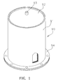
- the heat column 90 comprises a hollow column body 91, a lid 92 covered onto the top of the column body 91, a filling receptacle 93 formed on the lid 92 and provided for filling a liquid into the column body 91, and finally the heat column 90 is sealed.
- the column body 91 includes a contact surface 94 disposed at the bottom of the column body 91 contacted with a heat source, and the heat column is operated an operating mechanism as describe below.
- a liquid at a heat absorbing end (which is the contact surface 94) is vaporized into vapor to form an air flow.
- a local pressure is produced inside the column body 91 to drive the vapor to flow towards a heat discharging end (such as lid 92 or the internal wall of the column body 91), and the vapor is operated at the contact area of the heat discharging end and condensed into a liquid phase, and then the liquid loops back to the heat absorbing end (which is the contact surface 94) for circulation and heat dissipation through a natural phenomenon of a gravity/capillary siphon by a metal crystal, a metal powder sintered lump or a copper mesh on the internal wall of the column body 91.
- the heat column 90 can achieve the effect of the heat dissipation and circulation by means of the crystal, sintered lump or copper mesh on the internal wall of the column body 91 and changing the liquid/vapor phase to cool the vapor and liquid through the natural phenomenon of the gravity/capillary siphon, yet there is no appropriate partition of space in the column body 91, so that the air flow formed by the vaporized liquid descends when encountering the lid 92, and the descended airflow and the rising airflow constitute an opposite flushing, and a smooth circulation operation or a good heat dissipation effect cannot be achieved.
- the conventional heat column requires improvements. Therefore, it is an important subject for related manufacturers to overcome the drawbacks of the conventional heat column.
- the present invention provides a technical measure, comprising: a column body, being a sealed hollow cavity formed by a lid and a base, and provided for containing a liquid therein; and a partition element, being a hood plate obliquely extended towards the partition element, and fixed into the column body, and the partition element comprising a first channel formed on a side of the partition element opposite to the base, and a second channel formed on another side of the partition element opposite to the lid.
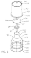
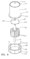
- the heat column 1 comprises a column body 12, a guide element 16 and a partition element 26, wherein the column body 12 is a hollow cavity; in other words, the column body 12 includes an operating space 120 therein, and a capillary structure such as a metal crystal, a metal powder sintered lumps, a copper mesh, a tube or a mesh tube is formed on a surface of the internal wall of the operating space 120 of the column body 12, and a connecting edge 121 is protruded from the bottom of the column body 12 (wherein the up, down, front and rear directions referred in the description of the present invention are used for the purpose of illustrating the invention only, but not intended for limiting the configuration of the invention in an erect position), and the connecting edge 121 includes a plurality of fixing holes 122 formed thereon, and a lid 14 is covered to the top of the column body 12, and the lid 14 includes a filling
- the column body 12 is vacuumed and sealed.
- the surface of the internal wall of the lid 14 also has the same capillary structure formed on the internal wall of the column body 12, and the lid 14 is tilted downward to facilitate guiding the airflow towards the column body 12, and a base 10 and an insulation gasket 28 (which is a hollow plate corresponding to the base in this preferred embodiment) include a plurality of fixing holes 101, 281 formed around the peripheries of the base 10 and the insulation gasket 28.
- the insulation gasket 28 is installed between the connecting edge 121 of the column body 12 and the base 10 and fixed into the fixing holes 122, 101 by a plurality of fasteners 30 (such as bolts) 281, so that the column body 12 and the base 10 are combined to form a sealed space of the column body for containing a liquid 40.
- the guide element 16 is fixed into the operating space 120 of the column body 12, and the guide element 16 includes an expanding circular portion 18 at the bottom and a guided ascending portion 20 at the top, and the expanding circular portion 18 is a circular plate slightly extended downward, and the width of the bottom of the expanding circular portion 18 is slightly smaller than the internal diameter of the column body 12 in this preferred embodiment, and the expanding circular portion 18 has a plurality of separately protruded positioning plates 181 installed at the bottom periphery of the expanding circular portion 18, and the positioning plate 181 (or another fixing method) is fixed onto the internal wall of the column body 12.
- the guided ascending portion 20 is a substantially vertical cylindrical plate, and a top plate 24 is installed at the top of the guided ascending portion 20, and a middle tube 22 is penetrated through the top plate 24 and includes a plurality of through holes 241 formed at the periphery of the middle tube 22 and disposed apart from one another, and the guide element 16 becomes a penetrating guide space 160, wherein a guided passing space 220 is formed inside the middle tube 22.
- the partition element 26 is fixed into the operating space 120 of the column body 12 and disposed at the top of the guide element 16, and the partition element 26 has a through hole 261 formed at the top, such that the whole partition element 26 is a hood plate expanded obliquely towards the base 10 to facilitate guiding an airflow towards the column body 12, and the partition element 26 has a bottom with a width slightly smaller than the internal diameter of the column body 12 in this preferred embodiment, and the partition element 26 includes a plurality of separately protruded positioning plates 262 installed at the bottom periphery of the partition element 26.
- the positioning plate 262 (or another fixing method) is fixed to the internal wall of the column body 12.
- the middle tube 22 is penetrated through and protruded from the through hole 261 of the partition element 26, and a circulation space 263 is formed between the top of the middle tube 22 and the lid 14, and the bottom of the middle tube 22 is disposed inside the guide space 160 of the guide element 16, and preferably situated at the bottom of the guided ascending portion 20.
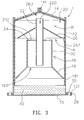
- a first channel A is formed between the partition element 26 and the guide element 16 and led to the internal wall of the column body 12
- a second channel B is formed between the lid 14 and the partition element 26 and led to the internal wall of the column body 12, and the plurality of partition elements 26 can be installed into the column body 12.
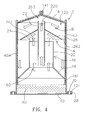
- Fig. 4 when the directional thermal siphon type heat column of the present invention is operated, the base 10 of the column body 12 is contacted with a heat source, so that the liquid 40 can absorb heat, and an airflow of the vaporized liquid 40 will rise and a portion of the airflow is passed to the partition element 26 through the guide space 160 of the guide element 16 and the plurality of through holes 241 of the top plate 24, and a portion of the airflow flows along the first channel A of the partition element 26 and obliquely downward to contact with the internal wall of the column body 12 to start the condensation and capillary (siphon) backflow action, so that the liquefied liquid 40 can achieve the heat absorbing and cooling effects.
- the other portion of the airflow of the vaporized liquid 40 is passed through the guided passing space 220 of the middle tube 22 to the circulation space 263 under the lid 14, and the other portion of the airflow flows along the second channel B of the lid 14 and obliquely downward to contact with the internal wall at the top of the column body 12 to start the condensation and capillary (siphon) backflow action, so that the airflow of the vaporized liquid 40 can be divided without causing any opposite flushing phenomenon to provide a smooth heat dissipation and circulation operation and improve the heat dissipating efficiency significantly.
- the internal wall of the column body 12 acts as a main area for the condensation, therefore the external wall of column body 12 in contact with the outside must be maintained at a low temperature condition, and the insulation gasket 28 installed between the column body 12 and the base 10 can prevent the heat source from passing through the path formed by the base 10, the fastener 30 and the connecting edge 121 or increasing the temperature of the external wall of the column body 12, so as to overcome the drawbacks of lowering the heat dissipating efficiency.
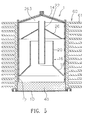
- FIG. 5 for a schematic view of a directional thermal siphon type heat column in accordance with the second preferred embodiment of the present invention
- the second referred embodiment further comprises an accessory heat sink 60 sheathed on an external side of the column body 12, and the accessory heat sink 60 includes a plurality of heat dissipating fins 61 for dissipating heat from an external wall of the column body 12.
- the third preferred embodiment is based on the structure with the column body 12 and the partition element 26 according to the first preferred embodiment, and a modification is made.
- the third preferred embodiment further comprises a middle tube 50 penetrated through the through hole 261 of the partition element 26 and abutted and positioned between the base 10 and the lid 14.
- the middle tube 50 includes a heat dissipating element 52 installed below the partition element 26, and the heat dissipating element 52 includes a plurality of heat dissipating fins 521 for guiding the air flow of the vaporized liquid 40 to improve the heat dissipation and circulation efficiency.
- the middle tube 50 includes a plurality of penetrating holes 51 formed at both upper and lower ends of the middle tube 50, so that the airflow of the vaporized liquid 40 can pass through the penetrating hole 51 at the lower end and enter into a guided passing space 501 of the middle tube 50 and then into the second channel B from the penetrating hole 51 at the upper end.
- this preferred embodiment is based on the structure with the column body 12, the partition element 26, the middle tube 50 and the heat dissipating element 52 according to the third preferred embodiment, and a modification is made, wherein the middle tube 50 is penetrated through the through hole 261 of the partition element 26, and an appropriate distance from both ends of the middle tube 50 to the base 10 and the lid 14 respectively is maintained, and the partition element 26 includes a plurality of heat dissipating fins 521 installed below and abutted against an internal wall of the column body 12 for supporting the partition element 26 to be fixed into the column body 12.
Landscapes
- Engineering & Computer Science (AREA)
- Theoretical Computer Science (AREA)
- Human Computer Interaction (AREA)
- Physics & Mathematics (AREA)
- General Engineering & Computer Science (AREA)
- General Physics & Mathematics (AREA)
- Cooling Or The Like Of Electrical Apparatus (AREA)
Applications Claiming Priority (1)
| Application Number | Priority Date | Filing Date | Title |
|---|---|---|---|
| TW099122543A TW201202647A (en) | 2010-07-08 | 2010-07-08 | Heat conductive column featuring directional thermosiphon |
Publications (1)
| Publication Number | Publication Date |
|---|---|
| EP2405321A2 true EP2405321A2 (de) | 2012-01-11 |
Family
ID=44587597
Family Applications (1)
| Application Number | Title | Priority Date | Filing Date |
|---|---|---|---|
| EP11005563A Withdrawn EP2405321A2 (de) | 2010-07-08 | 2011-07-07 | Ausgerichtete thermische Heizkolonne des Siphontyps |
Country Status (3)
| Country | Link |
|---|---|
| US (1) | US20120006515A1 (de) |
| EP (1) | EP2405321A2 (de) |
| TW (1) | TW201202647A (de) |
Family Cites Families (19)
| Publication number | Priority date | Publication date | Assignee | Title |
|---|---|---|---|---|
| US3568762A (en) * | 1967-05-23 | 1971-03-09 | Rca Corp | Heat pipe |
| US3537514A (en) * | 1969-03-12 | 1970-11-03 | Teledyne Inc | Heat pipe for low thermal conductivity working fluids |
| GB1263766A (en) * | 1969-09-16 | 1972-02-16 | English Electric Valve Co Ltd | Improvements in or relating to electron discharge tubes |
| GB1488662A (en) * | 1973-10-11 | 1977-10-12 | Secretary Industry Brit | Two-phase thermosyphons |
| US3986550A (en) * | 1973-10-11 | 1976-10-19 | Mitsubishi Denki Kabushiki Kaisha | Heat transferring apparatus |
| US4057963A (en) * | 1976-03-11 | 1977-11-15 | Hughes Aircraft Company | Heat pipe capable of operating against gravity and structures utilizing same |
| US4961463A (en) * | 1989-04-26 | 1990-10-09 | The United States Of America As Represented By The Secretary Of The Army | Thermosyphon condensate return device |
| DE3929024A1 (de) * | 1989-09-01 | 1991-03-14 | Deutsche Forsch Luft Raumfahrt | Heatpipe |
| JPH05118780A (ja) * | 1991-08-09 | 1993-05-14 | Mitsubishi Electric Corp | ヒートパイプ |
| KR100438825B1 (ko) * | 2001-10-29 | 2004-07-05 | 삼성전자주식회사 | 단열 수단을 구비하는 열 전달 장치 |
| TW506523U (en) * | 2002-03-29 | 2002-10-11 | Hon Hai Prec Ind Co Ltd | Heat pipe |
| US6571863B1 (en) * | 2002-08-27 | 2003-06-03 | Compal Electronics, Inc. | Turbulence inducing heat pipe for improved heat transfer rates |
| TW577969B (en) * | 2003-07-21 | 2004-03-01 | Arro Superconducting Technolog | Vapor/liquid separated heat exchanging device |
| US7322402B2 (en) * | 2004-01-05 | 2008-01-29 | Hul-Chun Hsu | Heat pipe structure and method for fabricating the same |
| TWI243885B (en) * | 2004-05-18 | 2005-11-21 | Benq Corp | Heat pipe structure with an external liquid detouring path |
| CN100573019C (zh) * | 2006-03-03 | 2009-12-23 | 富准精密工业(深圳)有限公司 | 热管 |
| DE102007027355A1 (de) * | 2007-06-11 | 2008-12-18 | Trithor Gmbh | Wärmerohr sowie Kühleinrichtung für die Kryotechnik |
| CN101573018B (zh) * | 2008-04-28 | 2012-03-21 | 富准精密工业(深圳)有限公司 | 散热装置 |
| US8517085B2 (en) * | 2008-09-03 | 2013-08-27 | Lenovo (Singapore) Pte. Ltd. | Vapor flow in heat pipe using centrifugal blower |
-
2010
- 2010-07-08 TW TW099122543A patent/TW201202647A/zh unknown
-
2011
- 2011-07-06 US US13/177,141 patent/US20120006515A1/en not_active Abandoned
- 2011-07-07 EP EP11005563A patent/EP2405321A2/de not_active Withdrawn
Non-Patent Citations (1)
| Title |
|---|
| None |
Also Published As
| Publication number | Publication date |
|---|---|
| TW201202647A (en) | 2012-01-16 |
| US20120006515A1 (en) | 2012-01-12 |
Similar Documents
| Publication | Publication Date | Title |
|---|---|---|
| CN101866887B (zh) | 散热装置 | |
| US20190041144A1 (en) | Phase change material evaporator and heat dissipating apparatus using the same | |
| US9261309B2 (en) | Loop heat pipe and manufacturing method thereof | |
| US8857502B2 (en) | Vapor chamber having heated protrusion | |
| JP5741354B2 (ja) | ループ型ヒートパイプ及び電子機器 | |
| US20090205812A1 (en) | Isothermal vapor chamber and support structure thereof | |
| US11486652B2 (en) | Thermosyphon heat sink | |
| US20060181848A1 (en) | Heat sink and heat sink assembly | |
| US20140055954A1 (en) | Heat pipe structure, and thermal module and electronic device using same | |
| US20080179044A1 (en) | Heat dissipating device | |
| CN101765352A (zh) | 扁平型热导管及使用该热导管的散热模组 | |
| US20230324130A1 (en) | Heat dissipation module and manufacturing method thereof | |
| KR101173767B1 (ko) | 열 확산 기능을 가지는 복합방열기구 | |
| US6666261B2 (en) | Liquid circulation cooler | |
| CN102168904A (zh) | 一种采用斯特林制冷机的酒柜 | |
| JP2009192728A (ja) | 表示装置 | |
| CN217403230U (zh) | 散热模块 | |
| CN114945259A (zh) | 整合式冷却模块及具有该整合式冷却模块的电子装置 | |
| CN102339801A (zh) | 具方向性热虹吸式的导热柱 | |
| EP2405321A2 (de) | Ausgerichtete thermische Heizkolonne des Siphontyps | |
| US20200232714A1 (en) | Heat dissipating device | |
| US20080308257A1 (en) | Heat dissipating assembly | |
| CN219372924U (zh) | 一种散热元件及热虹吸散热器 | |
| KR20120034182A (ko) | 열 확산 기능을 가지는 복합방열기구 | |
| CN201876170U (zh) | 具方向性热虹吸式的导热柱 |
Legal Events
| Date | Code | Title | Description |
|---|---|---|---|
| AK | Designated contracting states |
Kind code of ref document: A2 Designated state(s): AL AT BE BG CH CY CZ DE DK EE ES FI FR GB GR HR HU IE IS IT LI LT LU LV MC MK MT NL NO PL PT RO RS SE SI SK SM TR |
|
| AX | Request for extension of the european patent |
Extension state: BA ME |
|
| PUAI | Public reference made under article 153(3) epc to a published international application that has entered the european phase |
Free format text: ORIGINAL CODE: 0009012 |
|
| STAA | Information on the status of an ep patent application or granted ep patent |
Free format text: STATUS: THE APPLICATION IS DEEMED TO BE WITHDRAWN |
|
| 18D | Application deemed to be withdrawn |
Effective date: 20150203 |