EP2403124A2 - Zeitverzögerungsschütz für einen APU-Flugzeugstarter - Google Patents
Zeitverzögerungsschütz für einen APU-Flugzeugstarter Download PDFInfo
- Publication number
- EP2403124A2 EP2403124A2 EP11169864A EP11169864A EP2403124A2 EP 2403124 A2 EP2403124 A2 EP 2403124A2 EP 11169864 A EP11169864 A EP 11169864A EP 11169864 A EP11169864 A EP 11169864A EP 2403124 A2 EP2403124 A2 EP 2403124A2
- Authority
- EP
- European Patent Office
- Prior art keywords
- direct current
- current motor
- starter
- relay
- time
- Prior art date
- Legal status (The legal status is an assumption and is not a legal conclusion. Google has not performed a legal analysis and makes no representation as to the accuracy of the status listed.)
- Withdrawn
Links
- 239000007858 starting material Substances 0.000 title claims abstract description 35
- 230000000977 initiatory effect Effects 0.000 claims abstract description 7
- XUIMIQQOPSSXEZ-UHFFFAOYSA-N Silicon Chemical compound [Si] XUIMIQQOPSSXEZ-UHFFFAOYSA-N 0.000 claims description 11
- 229910052710 silicon Inorganic materials 0.000 claims description 11
- 239000010703 silicon Substances 0.000 claims description 11
- 238000000034 method Methods 0.000 claims description 8
- 230000005669 field effect Effects 0.000 claims description 3
- 239000004065 semiconductor Substances 0.000 claims description 3
- 230000003111 delayed effect Effects 0.000 claims 2
- 230000035939 shock Effects 0.000 description 4
- 230000001133 acceleration Effects 0.000 description 2
- 230000000694 effects Effects 0.000 description 2
- 230000001960 triggered effect Effects 0.000 description 2
- 230000004075 alteration Effects 0.000 description 1
- 239000003990 capacitor Substances 0.000 description 1
- 230000006835 compression Effects 0.000 description 1
- 238000007906 compression Methods 0.000 description 1
- 238000006467 substitution reaction Methods 0.000 description 1
Images
Classifications
-
- F—MECHANICAL ENGINEERING; LIGHTING; HEATING; WEAPONS; BLASTING
- F02—COMBUSTION ENGINES; HOT-GAS OR COMBUSTION-PRODUCT ENGINE PLANTS
- F02N—STARTING OF COMBUSTION ENGINES; STARTING AIDS FOR SUCH ENGINES, NOT OTHERWISE PROVIDED FOR
- F02N15/00—Other power-operated starting apparatus; Component parts, details, or accessories, not provided for in, or of interest apart from groups F02N5/00 - F02N13/00
- F02N15/02—Gearing between starting-engines and started engines; Engagement or disengagement thereof
- F02N15/022—Gearing between starting-engines and started engines; Engagement or disengagement thereof the starter comprising an intermediate clutch
-
- F—MECHANICAL ENGINEERING; LIGHTING; HEATING; WEAPONS; BLASTING
- F02—COMBUSTION ENGINES; HOT-GAS OR COMBUSTION-PRODUCT ENGINE PLANTS
- F02C—GAS-TURBINE PLANTS; AIR INTAKES FOR JET-PROPULSION PLANTS; CONTROLLING FUEL SUPPLY IN AIR-BREATHING JET-PROPULSION PLANTS
- F02C7/00—Features, components parts, details or accessories, not provided for in, or of interest apart form groups F02C1/00 - F02C6/00; Air intakes for jet-propulsion plants
- F02C7/26—Starting; Ignition
- F02C7/268—Starting drives for the rotor, acting directly on the rotor of the gas turbine to be started
- F02C7/275—Mechanical drives
-
- F—MECHANICAL ENGINEERING; LIGHTING; HEATING; WEAPONS; BLASTING
- F02—COMBUSTION ENGINES; HOT-GAS OR COMBUSTION-PRODUCT ENGINE PLANTS
- F02N—STARTING OF COMBUSTION ENGINES; STARTING AIDS FOR SUCH ENGINES, NOT OTHERWISE PROVIDED FOR
- F02N11/00—Starting of engines by means of electric motors
- F02N11/08—Circuits specially adapted for starting of engines
- F02N11/0851—Circuits specially adapted for starting of engines characterised by means for controlling the engagement or disengagement between engine and starter, e.g. meshing of pinion and engine gear
-
- F—MECHANICAL ENGINEERING; LIGHTING; HEATING; WEAPONS; BLASTING
- F02—COMBUSTION ENGINES; HOT-GAS OR COMBUSTION-PRODUCT ENGINE PLANTS
- F02N—STARTING OF COMBUSTION ENGINES; STARTING AIDS FOR SUCH ENGINES, NOT OTHERWISE PROVIDED FOR
- F02N2300/00—Control related aspects of engine starting
- F02N2300/20—Control related aspects of engine starting characterised by the control method
- F02N2300/2011—Control involving a delay; Control involving a waiting period before engine stop or engine start
-
- F—MECHANICAL ENGINEERING; LIGHTING; HEATING; WEAPONS; BLASTING
- F05—INDEXING SCHEMES RELATING TO ENGINES OR PUMPS IN VARIOUS SUBCLASSES OF CLASSES F01-F04
- F05D—INDEXING SCHEME FOR ASPECTS RELATING TO NON-POSITIVE-DISPLACEMENT MACHINES OR ENGINES, GAS-TURBINES OR JET-PROPULSION PLANTS
- F05D2220/00—Application
- F05D2220/50—Application for auxiliary power units (APU's)
Definitions
- the subject matter disclosed herein relates to an auxiliary power unit (APU) for aircraft. More specifically, the subject disclosure relates to a starter motor for an APU.
- APU auxiliary power unit
- An APU is utilized in an aircraft primarily to provide power to start the engines. Aircraft engines have large heavy rotors that must be accelerated to a high rotational speed in order to provide sufficient air compression for self-sustaining operation.
- An APU solves this problem by powering up the aircraft in two stages.
- the APU is started by an APU starter, which is a DC electric motor with power supplied by a battery, accumulator, or external power source such as a ground power unit. Once the APU accelerates to full speed, it can provide enough power to start the aircraft's main engines, either by turning an electrical generator or a hydraulic pump, or by providing compressed air to the air turbine of the starter motor.
- a starter for an auxiliary power unit includes a direct current motor operably connectable to an auxiliary power unit.
- a clutch is arranged in an electrically parallel relationship and configured to operably connect the motor to the auxiliary power unit when engaged, the motor and the clutch being powered by a common input line.
- a time delay switching element is located and configured to delay electrical current delivery to the motor thus providing for full engagement of the clutch prior to initiation of rotation of the motor.
- a method of starting an auxiliary power unit includes providing a flow of electrical current to a clutch of a starter.
- the clutch is fully engaged via the flow of current, thus operably connecting the direct current motor to the auxiliary power unit.
- a time-delayed flow of electrical current is provided to a direct current motor of the starter located such that it shares a common input line with the clutch.
- the direct current motor is accelerated via the time-delayed flow of current, and rotational energy is transferred from the direct current motor to the auxiliary power unit.
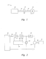
- FIG. 1 is a schematic view of an embodiment of a starter for a auxiliary power unit
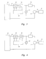
- FIG. 2 is an electrical schematic view of an embodiment of a starter for an auxiliary power unit
- FIG. 3 is an electrical schematic view of another embodiment of a starter for an auxiliary power unit
- FIG. 4 is an electrical schematic view of yet another embodiment of a starter for an auxiliary power unit.
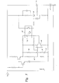
- FIG. 5 is an electrical schematic of still another embodiment of a starter for an auxiliary power unit.
- FIG. 1 Shown in FIG. 1 is a schematic of a starter 10 for an auxiliary power unit (APU) 12.
- the starter 10 includes an electric motor, for example, a direct current (DC) motor 14 and a motor shaft 18 extending therefrom.
- a starter shaft 20 extends from the APU 12 and is connectable to the motor shaft 18 via a clutch 22. When the clutch 22 is engaged, rotational energy is transferred from the DC motor 14, through the motor shaft 18 and starter shaft 20, and to the APU 12.
- DC direct current
- the DC motor 14 and the clutch 22 are arranged in an electrically parallel relationship and are powered by a common input line 24 from a power supply 26.
- An APU controller 28 controls a flow of current through the input line 24 via signals to one or more contactors 30.
- the DC motor 14 accelerates up to a desired rotational speed.
- the clutch 22 operably connects a starter shaft 20 to the motor shaft 18 thus enabling the transfer of rotational energy from the DC motor 14 to the APU 12.
- a time delay switching element for example, a relay 32.
- time delay control electronics that drive the relay 32 are activated, thus initiating a time delay, before the current flows to the DC motor 14.
- the time delay effect of the relay 32 allows the clutch 22 to fully engage prior to initiation of acceleration of the DC motor 14 thus reducing torque shock when the clutch 22 is engaged.
- MOSFET 34 metal-oxide-semiconductor field-effect transistor 34 which acts as the time delay switching element.
- the MOSFET 34 is arranged in a serial relationship with the DC motor 14. When current passes through the input line 24 to the MOSFET 34, time delay control electronics that drive the MOSFET 34 are activated, thus initiating a time delay, before the current proceeds to the DC motor 14. The time delay effect of the MOSFET 34 allows the clutch 22 to fully engage prior to initiation of acceleration of the DC motor 14.
- starter 10 include a switching element which is a thyristor 36.
- a switching element which is a thyristor 36.
- the relay 32 and the MOSFET 34 when current is delivered to the thyristor 36 via the input line 24, a time delay is initiated via the time delay control electronics that drive the thyristor 36.
- the thyristor 36 Once the thyristor 36 is triggered, it will continue to conduct, or provide current to the DC motor 14 until the voltage across the thyristor 36 is reversed. In other words, the thyristor 36 is latched in a closed position. Further, the thyristor 36 is operable at a wide range of temperatures, and those as low as -50 degrees Celsius or lower.
- the desired range of time delay is in a range of about 0.250 seconds to 2.0 seconds, with a target delay of about 0.500 seconds to allow the clutch 22 to fully engage prior to supplying current to the DC motor 14 to prevent damage to the starter shaft 20 and/or other elements of the starter 10 or APU 12.
- FIG. 5 illustrates another embodiment.
- Voltage V in is turned on via the contactors 30 (shown in FIG. 4 ).
- the time delay is established via a comparator 40 which trips a relay 42 to provide power to a silicon-controlled rectifier (SCR) 44.
- the relay may be optically driven relay with an internal light emitting diode 54 configured to change a switch state of the relay 42.
- the comparator 40 compares a comparator reference voltage 46 to a time-delayed voltage 48.
- the time-delay is created by a resistor 50 and capacitor 52. When the time-delayed voltage exceeds the reference voltage, the comparator 40 trips the relay 42 which, in turn energizes the SCR 44.
- the SCR 44 can energize a second SCR 56 in response to the SCR 44 being energized by the relay 42 to provide current to the DC motor 14. Because of the time delay provided by the comparator 40, the current is provided to the DC motor 14 after current is provided to the clutch 22 (shown in FIG. 4 ) and the clutch 22 is fully engaged.
Landscapes
- Engineering & Computer Science (AREA)
- Chemical & Material Sciences (AREA)
- Combustion & Propulsion (AREA)
- Mechanical Engineering (AREA)
- General Engineering & Computer Science (AREA)
- Control Of Direct Current Motors (AREA)
- Connection Of Motors, Electrical Generators, Mechanical Devices, And The Like (AREA)
- Motor And Converter Starters (AREA)
Applications Claiming Priority (2)
| Application Number | Priority Date | Filing Date | Title |
|---|---|---|---|
| US12/815,515 US8779609B2 (en) | 2010-06-15 | 2010-06-15 | Time delay contactor for aircraft APU starter |
| US12/959,471 US8222848B2 (en) | 2010-06-15 | 2010-12-03 | Time delay contactor for aircraft APU starter |
Publications (1)
| Publication Number | Publication Date |
|---|---|
| EP2403124A2 true EP2403124A2 (de) | 2012-01-04 |
Family
ID=44971140
Family Applications (1)
| Application Number | Title | Priority Date | Filing Date |
|---|---|---|---|
| EP11169864A Withdrawn EP2403124A2 (de) | 2010-06-15 | 2011-06-14 | Zeitverzögerungsschütz für einen APU-Flugzeugstarter |
Country Status (3)
| Country | Link |
|---|---|
| US (1) | US8222848B2 (de) |
| EP (1) | EP2403124A2 (de) |
| JP (1) | JP2012001203A (de) |
Families Citing this family (3)
| Publication number | Priority date | Publication date | Assignee | Title |
|---|---|---|---|---|
| US8779609B2 (en) * | 2010-06-15 | 2014-07-15 | Hamilton Sundstrand Corporation | Time delay contactor for aircraft APU starter |
| US8808142B2 (en) | 2012-04-09 | 2014-08-19 | Hamilton Sundstrand Corporation | Aircraft APU electrical starter torque limiter |
| KR102278515B1 (ko) * | 2021-02-18 | 2021-07-19 | 김포서비스(주) | 차량용 재제조 알터네이터 및 스타터 모터의 성능 시험 장치 |
Family Cites Families (18)
| Publication number | Priority date | Publication date | Assignee | Title |
|---|---|---|---|---|
| JPS52121112A (en) * | 1976-04-05 | 1977-10-12 | Hitachi Ltd | Clutch mechanism of gas turbine |
| JPS5462412A (en) * | 1977-10-26 | 1979-05-19 | Kawasaki Heavy Ind Ltd | Starter of gas turbine |
| US4901690A (en) * | 1988-12-12 | 1990-02-20 | General Motors Corporation | Electronic starting motor system having timed cranking period control |
| US5899411A (en) | 1996-01-22 | 1999-05-04 | Sundstrand Corporation | Aircraft electrical system providing emergency power and electric starting of propulsion engines |
| US5977645A (en) | 1997-06-30 | 1999-11-02 | Sundstrand Corporation | Aircraft secondary power system |
| JP3892570B2 (ja) * | 1998-02-13 | 2007-03-14 | 株式会社東芝 | インバータ制御ターニング装置 |
| US6462429B1 (en) | 2000-02-24 | 2002-10-08 | Hamilton Sundstrand Corporation | Induction motor/generator system |
| JP2001342935A (ja) * | 2000-06-01 | 2001-12-14 | Mitsubishi Electric Corp | 内燃機関始動装置 |
| US6443035B1 (en) * | 2001-09-20 | 2002-09-03 | The Boeing Company | Hybrid power input quill for transmissions |
| US6777822B1 (en) | 2003-04-01 | 2004-08-17 | Hamilton Sundstrand Corporation | Control system for an auxiliary power unit |
| US7253535B2 (en) | 2005-09-15 | 2007-08-07 | Hamilton Sundstrand Corporation | Electrical starter generator system for a gas turbine engine |
| JP2007113568A (ja) * | 2005-09-22 | 2007-05-10 | Denso Corp | 常時噛合い式スタータ |
| US7448220B2 (en) | 2005-10-19 | 2008-11-11 | Hamilton Sundstrand Corporation | Torque control for starting system |
| FR2907761B1 (fr) | 2006-10-27 | 2009-07-03 | Airbus France Sas | Dispositif de generation electrique d'un aeronef et de demarrage electrique d'un reacteur a bord d'un aeronef |
| US7840333B2 (en) | 2007-03-30 | 2010-11-23 | Hamilton Sundstrand Corporation | Event-driven starter controller |
| JP4702427B2 (ja) * | 2008-10-10 | 2011-06-15 | 株式会社デンソー | エンジン始動制御装置 |
| US8299639B2 (en) * | 2009-04-17 | 2012-10-30 | Denso Corporation | Starter for starting internal combustion engine |
| US8779609B2 (en) * | 2010-06-15 | 2014-07-15 | Hamilton Sundstrand Corporation | Time delay contactor for aircraft APU starter |
-
2010
- 2010-12-03 US US12/959,471 patent/US8222848B2/en active Active
-
2011
- 2011-06-09 JP JP2011129006A patent/JP2012001203A/ja not_active Ceased
- 2011-06-14 EP EP11169864A patent/EP2403124A2/de not_active Withdrawn
Non-Patent Citations (1)
| Title |
|---|
| None |
Also Published As
| Publication number | Publication date |
|---|---|
| JP2012001203A (ja) | 2012-01-05 |
| US20110304158A1 (en) | 2011-12-15 |
| US8222848B2 (en) | 2012-07-17 |
Similar Documents
| Publication | Publication Date | Title |
|---|---|---|
| JP6509874B2 (ja) | タービンエンジンを確実に始動させるための方法およびシステム | |
| EP2028104B1 (de) | Generator für einen Gasturbinenmotor mit DC-Busfehlerkurzschlusssteuerung unter Verwendung einer Batterie | |
| EP2028758B1 (de) | Motor mit Energiebusfehlerkurzschlusssteuerung mit einem Trennschalter | |
| EP2797769B1 (de) | Verfahren und vorrichtung zum hochfahren eines dc verteilsystems in einem hybrdifahrzeug | |
| RU2673033C2 (ru) | Способ и система быстрой реактивации газотурбинного двигателя | |
| JP2011017337A (ja) | 補助電源を持つ燃焼及び緊急起動制御システム | |
| CN102251900B (zh) | 发动机起动装置 | |
| JP2011001956A (ja) | 分離式補助電源の燃焼及び起動システム | |
| CN103269888A (zh) | 用于非公路车辆发动机曲柄起动的系统和方法 | |
| US8808142B2 (en) | Aircraft APU electrical starter torque limiter | |
| US8222848B2 (en) | Time delay contactor for aircraft APU starter | |
| US8779609B2 (en) | Time delay contactor for aircraft APU starter | |
| EP2783986A2 (de) | Hydraulikpumpestartsystem und -verfahren | |
| WO2014199772A1 (ja) | エンジン始動装置およびエンジン始動制御方法 | |
| US20150298797A1 (en) | Aircraft Having A System For Influencing The Yaw Moment And A Method For Influencing The Yaw Moment Of An Aircraft | |
| US11384694B2 (en) | Auxiliary device system of aircraft engine | |
| JP4799641B2 (ja) | エンジン始動装置 | |
| TWI607925B (zh) | Hybrid system and its operation method | |
| US11190118B2 (en) | System for controlling electrical power generated by a permanent magnet machine | |
| US20130000585A1 (en) | Starter supply network | |
| CZ2016689A3 (cs) | Zařízení a způsob pro startování pomocné jednotky | |
| RU94522U1 (ru) | Система запуска дизеля тепловоза | |
| TH65932B (th) | อุปกรณ์ควบคุมการสตาร์ตเครื่องยนต์ | |
| TH161333A (th) | อุปกรณ์ควบคุมการสตาร์ตเครื่องยนต์ |
Legal Events
| Date | Code | Title | Description |
|---|---|---|---|
| AK | Designated contracting states |
Kind code of ref document: A2 Designated state(s): AL AT BE BG CH CY CZ DE DK EE ES FI FR GB GR HR HU IE IS IT LI LT LU LV MC MK MT NL NO PL PT RO RS SE SI SK SM TR |
|
| AX | Request for extension of the european patent |
Extension state: BA ME |
|
| PUAI | Public reference made under article 153(3) epc to a published international application that has entered the european phase |
Free format text: ORIGINAL CODE: 0009012 |
|
| STAA | Information on the status of an ep patent application or granted ep patent |
Free format text: STATUS: THE APPLICATION HAS BEEN WITHDRAWN |
|
| 18W | Application withdrawn |
Effective date: 20140502 |