EP2401903B1 - Schalteinrichtung für eine landwirtschaftliche Verteilmaschine zum Ausbringen von Saatgut und/oder Dünger - Google Patents
Schalteinrichtung für eine landwirtschaftliche Verteilmaschine zum Ausbringen von Saatgut und/oder Dünger Download PDFInfo
- Publication number
- EP2401903B1 EP2401903B1 EP11166655A EP11166655A EP2401903B1 EP 2401903 B1 EP2401903 B1 EP 2401903B1 EP 11166655 A EP11166655 A EP 11166655A EP 11166655 A EP11166655 A EP 11166655A EP 2401903 B1 EP2401903 B1 EP 2401903B1
- Authority
- EP
- European Patent Office
- Prior art keywords
- switching
- switching member
- distribution machine
- switching device
- sleeve
- Prior art date
- Legal status (The legal status is an assumption and is not a legal conclusion. Google has not performed a legal analysis and makes no representation as to the accuracy of the status listed.)
- Active
Links
Images




Classifications
-
- A—HUMAN NECESSITIES
- A01—AGRICULTURE; FORESTRY; ANIMAL HUSBANDRY; HUNTING; TRAPPING; FISHING
- A01C—PLANTING; SOWING; FERTILISING
- A01C19/00—Arrangements for driving working parts of fertilisers or seeders
- A01C19/04—Arrangements for driving working parts of fertilisers or seeders by a ground-engaging wheel
- A01C19/045—Arrangements for driving working parts of fertilisers or seeders by a ground-engaging wheel the drive coupling being controlled by lifting or lowering of the seeding tools
-
- A—HUMAN NECESSITIES
- A01—AGRICULTURE; FORESTRY; ANIMAL HUSBANDRY; HUNTING; TRAPPING; FISHING
- A01C—PLANTING; SOWING; FERTILISING
- A01C19/00—Arrangements for driving working parts of fertilisers or seeders
Definitions
- the invention relates to a switching device with a first switching state upon adjustment of a working device of an agricultural distribution machine from a first position to a second position and with a second switching state when returning from the second position to the first position according to claim 1. Furthermore, the present invention relates to a distributor for the distribution of seed / fertilizer according to claim 9.
- the DE 297 22 396 U1 describes a hydraulic cylinder with a link circuit.
- the DE 10038595 A1 describes a cylinder with a switching device for agricultural machinery.
- the DE 10 2008 050 783 A1 describes a drawn seeder with a driven by a drive device metering device, wherein the drive device is designed as a piston having a hydraulic cylinder formed shut-off device for interrupting the drive shaft having drive the metering device.
- the European patent EP 0 650 660 B1 describes the switching on and off of seed application by means of a tail wheel associated with the disadvantage that the switching on and off due to the inertia of the system is offset in time, since the seed is only transported with rotation of the tail wheel to the coulters.
- Object of the present invention is to provide a structurally simple, tug-independent and extremely reliable switching device and corresponding distributor.
- the invention is based on the idea to provide instead of a complicated path or angle measurement switching means, which serve to detect the first and second switching state according to claim 1.
- a complicated path or angle measurement switching means which serve to detect the first and second switching state according to claim 1.
- the advantage of switching means is not only in the cheaper production, but also in the more reliable operation.
- the switching device is designed in particular as a headland switching device.
- the switching means in particular by means of a, preferably just a single, attached to the first switching element actuating means, in particular switch, preferably buttons, a relative movement of the first switching element relative to the second switching element after a change in direction is detected.
- the detection of the relative movement does not mean that the path or the movement as such, for example the speed, is detected, but rather a state or the state change that can be detected as the first or second switching state of the switching device.
- the switching device according to the invention is therefore limited to detect a caused by the change in direction of the relative movement of the first switching element relative to the second switching element actuation of the switching means, in particular actuating means.
- the first switching element along the second switching element by the switching means in particular by means of a slider, preferably a second switching member at least partially, in particular frictionally, enclosing shift sleeve, is guided.
- mechanical components such as gears, gears or other rotating components in the switching means according to the present invention can advantageously be dispensed with.
- the switching means in particular by the actuating means, preferably the switch, the relative movement of the switching sleeve relative to the first switching element after a change in direction is detected, particularly simple and reliable switches such as proximity switches or switches can be provided with advantage.
- Another advantage is that sufficient by the additional switching sleeve and the linear or translational movement of the switching elements, a single switch for detecting the switching states.
- the switching sleeve has a with the stops, in particular the slot cooperating extension, in particular in the form of a pin. In this way, a structurally simple and reliable determination of the switching states is made possible.
- an extension or the extension described above for detecting the movement of the shift sleeve is provided by the switch.
- the first switching element is a cylinder tube of an actuating cylinder for adjusting the distributor between the working position and the headland position or the first switching element is attached thereto.
- the second switching element is a piston rod of the actuating cylinder or is coupled thereto in the direction of the longitudinal axis of the second switching element without translational degree of freedom. In this way, the switching device is space-saving and structurally simple manner and by exploiting synergy effects at least partially integrated in necessary for the operation of the distributor actuating cylinder.
- actuating cylinder in particular pneumatic, electrical, but more preferably hydraulic cylinders come into question.
- the distribution machine according to the present invention can be improved by arranging the switching device on the working device, wherein the working device can be a seed drill or a track marker.
- FIG. 1 In the FIG. 1 is a distributor 3 for the distribution of stored in a storage tank 22 seed / fertilizer shown here for simplicity not shown conveyor and coulters 20 in an agricultural soil.
- the coulters are part of a working device 2 of the distributor 3 and the distributor 3 also has a chassis 21.
- the sowing When turning the distributor 3 at the edge of the field, so on the headland, the sowing is interrupted and the working device 2 is raised so that processing of the soil is avoided. Both that Lifting the working equipment 2 as well as exhibiting the sowing on the headland should be as reliable as possible at the edge of the field. On the other hand, the sowing should not be interrupted by a malfunction of the switching device 1 while driving over the soil.
- FIG. 1 shown embodiment of the distributor 3 The lifting of the working device 2 and thus the coulters 20 away from the soil takes place in the in FIG. 1 shown embodiment of the distributor 3 by rotation of the working device 2 to a arranged on the chassis 21 joint.
- the rotation is effected by the retraction and extension of a here designed as a hydraulic cylinder actuating cylinder 18.
- the actuating cylinder 18 is articulated with its piston rod 19 on the working device 2 articulated, while the cylinder tube 17 of the actuating cylinder 18 is hinged at the opposite end of the actuating cylinder 18 hinged to a support frame 5 of the distributor 3.
- the storage tank 22 and the chassis 21 are mounted on the support frame 5
- the distributor 3 can be coupled via the holding frame 5 with a tractor pulling the distributor 3 in a direction of travel F.
- a retraction of the actuating cylinder 18 causes in the in FIG. 1 3, a lifting of the working device 2 from a first position (FIG. Fig. 2 ) for applying the seed / fertilizer on the field soil to a second position (headland position, Fig. 3 ) for turning at the edge of the field.
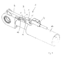
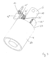
- switching means 9 in the form of a first switching element 4 and a second switching element 6 displaceably guided in the first switching element 4 as well as a switch 10 and a switching sleeve 11 are provided on the adjusting cylinder 18.
- the first switching element 4 is fixed on the holding frame 5 via a contact plate 15 fixed to the cylinder tube 17 without a translatory degree of freedom in the direction of a longitudinal axis 7 of the first switching element 4.
- the cylinder tube 17 is therefore only, as described above, free in the rotational direction to allow the pivoting movement of the working device 2 when raising or lowering.
- the first switching element 4 is designed as a guide tube or sleeve, on the circular cylindrical inner wall, the second switching element 6 is slidably guided with play.
- the second switching element 6, here in the form of a circular cylindrical cross-section rod is fixed to a provided for coupling the piston rod 19 with the working device 2 coupling member 23 on the working device 2, and also without translational degree of freedom in the direction of a longitudinal axis 8 of the second switching element. 6
- the longitudinal axis 8 is aligned in the embodiment shown here with the longitudinal axis 7, since the second switching element 6 is guided in the first switching element 4.
- the second switching element 6 performs a movement corresponding to the movement of the piston rod 19 relative to the cylinder tube 17 with respect to the first switching element 4.
- the movement is also proportional to the movement of the working device 2 relative to the holding frame 5.
- the switching sleeve 11 is with its longitudinal axis 24, which in the in FIG. 2 shown embodiment coincides with the longitudinal axis 7 and the longitudinal axis 8, guided along the second switching member 6 and slidably.
- the frictional connection is made according to FIG. 4 from a friction ring 26, which is inserted into an annular groove 25 on the inner circumference of the shift sleeve 11 and bears against the outer circumference of the second shift member 6.
- the resulting frictional force of the friction joint for example, by providing a plurality of friction rings 26 side by side, can be adapted to the respective needs.
- the friction ring consists in particular of rubber, while the second switching element 6 in particular consists of metal, as well as the switching sleeve 11, which may also be made of plastic.
- a snap ring made of plastic is conceivable according to the invention, or a shift sleeve made of two plastic shells, which are held by screw on the piston and wherein the screw force determines the friction factor.
- the switching means with a pair of materials that performs a friction with each other, but not or only slightly wears / abrasion subject.
- the elongated hole 14 in the switching plate 15, in which the pin 16 is moved during the extension and retraction of the actuating cylinder 18 back and forth, extends parallel to the longitudinal axis 7, longitudinal axis 8 and the longitudinal axis 24th
- the movement of the pin 16 thus always follows at the beginning of a change of direction of the movement of the adjusting cylinder 18, in particular the Piston rod 19 until the pin abuts the opposite stop 12, 13.
- the switch 10 By the switch 10, the first and the second switching state of the pin 16 can be detected, so that immediately at the beginning of a change in direction or after a length of the slot 14 corresponding stroke of the shift sleeve 11 by the second switching element 6 reliable switching of the distributor, in particular sowing into a non-emergency operation.
- the switching takes place at the earliest possible and optimal time, with a time-shifted switching invention is conceivable.
- a path calculation as in the prior art is omitted, whereby the switching device according to the invention works independently. It is even an operation directly through the switch 10 conceivable.
- the invention allows a reliable display of the switching states.
- the switch 10 is preferably designed as an inductive sensor and due to the matching translation direction of the movable components of the switching device 1, a single switch 10 is sufficient for detecting the two switching states of the switching device.
- the switching device 1 according to the present invention is easy to install and has extremely fast reaction times, since extremely short switching paths are made possible. Furthermore, the switching device according to the invention is independent of how large the stroke of the actuating cylinder is in an individual case.
- a less expensive switching plate 15 ' is provided, which is also fixed to the cylinder tube 17 and has an L-shaped basic shape.
- the switch 10 is in contrast to the arrangement of the switch 10 according to FIGS. 3 to 5 arranged rotated by 180 degrees.
- a pin 16 ' for limiting the movement of the switching sleeve 11' in the slot 14 'and a second pin 16 "opposite to the pin 16' on the switching sleeve 11 'arranged on the second pin 16" is detected by the switch 10, the switching state.
- the switching plate 15 ' serves, at the same time as a second switching element 6, by the first switching element 4 in an opening of the switching plate 15' is slidably guided.
- the inventive design of the switching device 1 according to FIGS. 8 and 9 is characterized by the fact that the cylinder tube 17 simultaneously serves as a first switching element 4, while the piston rod 19 is simultaneously provided as a second switching element 6.
- the trained as a switching sleeve 11 "slider is dimensioned correspondingly larger and is taken directly from the piston rod 19 by the shift sleeve 11" surrounds the piston rod 19.
- a switching plate 15 " is attached to an end face 27 of the cylinder tube 17 and provided with a slot 14 ', which is penetrated by a pin 16' as” formed extension of the switching sleeve 11 ".
- the described Schait painen 1 are particularly useful for a circuit in which an adjustment of one or more, in particular connected in series, responsible for increasing the coulter pressure actuating cylinder 18 to increase the coulter pressure, so that the first and second switching state of each actuator cylinder 18 is detected. With the circuit can then be controlled by means of a control device, the seed application, in particular by connecting the switching device to the control device of the tractor.
Landscapes
- Life Sciences & Earth Sciences (AREA)
- Soil Sciences (AREA)
- Environmental Sciences (AREA)
- Fertilizing (AREA)
- Sowing (AREA)
Priority Applications (1)
| Application Number | Priority Date | Filing Date | Title |
|---|---|---|---|
| PL11166655T PL2401903T3 (pl) | 2010-07-02 | 2011-05-19 | Urządzenie przełącznikowe do rolniczego rozdzielacza do wysiewu ziarna i/lub nawozów |
Applications Claiming Priority (1)
| Application Number | Priority Date | Filing Date | Title |
|---|---|---|---|
| DE102010025944A DE102010025944A1 (de) | 2010-07-02 | 2010-07-02 | Schalteinrichtung für eine landwirtschaftliche Verteilmaschine zum Ausbringen von Saatgut und/oder Dünger |
Publications (2)
| Publication Number | Publication Date |
|---|---|
| EP2401903A1 EP2401903A1 (de) | 2012-01-04 |
| EP2401903B1 true EP2401903B1 (de) | 2013-03-20 |
Family
ID=44117829
Family Applications (1)
| Application Number | Title | Priority Date | Filing Date |
|---|---|---|---|
| EP11166655A Active EP2401903B1 (de) | 2010-07-02 | 2011-05-19 | Schalteinrichtung für eine landwirtschaftliche Verteilmaschine zum Ausbringen von Saatgut und/oder Dünger |
Country Status (5)
| Country | Link |
|---|---|
| EP (1) | EP2401903B1 (pl) |
| DE (1) | DE102010025944A1 (pl) |
| DK (1) | DK2401903T3 (pl) |
| ES (1) | ES2415168T3 (pl) |
| PL (1) | PL2401903T3 (pl) |
Families Citing this family (3)
| Publication number | Priority date | Publication date | Assignee | Title |
|---|---|---|---|---|
| FR3028379B1 (fr) | 2014-11-18 | 2017-03-31 | Kuhn Sa | Machine agricole avec un dispositif de commutation a detection angulaire |
| CN107781257B (zh) * | 2017-11-22 | 2023-06-20 | 北京起重运输机械设计研究院有限公司 | 油缸位移检测装置 |
| DE102022110628A1 (de) | 2022-05-02 | 2023-11-02 | Amazonen-Werke H. Dreyer SE & Co. KG | Verfahren zum Steuern der Aushubstellung an einer landwirtschaftlichen Anbaumaschine, Steuersystem und Anbaumaschine |
Citations (1)
| Publication number | Priority date | Publication date | Assignee | Title |
|---|---|---|---|---|
| DE10038595A1 (de) * | 2000-08-08 | 2002-03-28 | Deere & Co | Steuervorrichtung einer Koppelstange |
Family Cites Families (8)
| Publication number | Priority date | Publication date | Assignee | Title |
|---|---|---|---|---|
| DE2701691C2 (de) * | 1977-01-17 | 1979-02-22 | A.J. Troester Gmbh & Co Kg, 6308 Butzbach | Drillmaschine |
| EP0281761B1 (de) * | 1987-02-12 | 1991-06-12 | Amazonen-Werke H. Dreyer GmbH & Co. KG | Einzelkorndrillmaschine |
| DE3709526A1 (de) * | 1987-03-25 | 1988-10-13 | Amazonen Werke Dreyer H | Verteilmaschine |
| DE9316622U1 (de) | 1993-11-02 | 1994-01-05 | Rabewerk Gmbh + Co, 49152 Bad Essen | Verteilmaschine zum Ausbringen eines Verteilgutes |
| US5896966A (en) * | 1997-05-02 | 1999-04-27 | Schmelzle; Douglas Martin | Hydraulic seed clutch actuator for seed drills |
| DE29722396U1 (de) * | 1997-12-18 | 1998-10-22 | Wilhelm Karmann GmbH, 49084 Osnabrück | Hydraulikzylinder |
| DE102004014063A1 (de) * | 2004-03-23 | 2005-10-13 | Rabe Agrarsysteme Gmbh & Co. Kg | Verteilmaschine zum Ausbringen von Verteilgütern |
| DE102008050783A1 (de) * | 2008-10-08 | 2010-04-15 | Amazonen-Werke H. Dreyer Gmbh & Co. Kg | Gezogene Sämaschine |
-
2010
- 2010-07-02 DE DE102010025944A patent/DE102010025944A1/de not_active Withdrawn
-
2011
- 2011-05-19 ES ES11166655T patent/ES2415168T3/es active Active
- 2011-05-19 EP EP11166655A patent/EP2401903B1/de active Active
- 2011-05-19 PL PL11166655T patent/PL2401903T3/pl unknown
- 2011-05-19 DK DK11166655.8T patent/DK2401903T3/da active
Patent Citations (1)
| Publication number | Priority date | Publication date | Assignee | Title |
|---|---|---|---|---|
| DE10038595A1 (de) * | 2000-08-08 | 2002-03-28 | Deere & Co | Steuervorrichtung einer Koppelstange |
Also Published As
| Publication number | Publication date |
|---|---|
| EP2401903A1 (de) | 2012-01-04 |
| DE102010025944A1 (de) | 2012-01-05 |
| PL2401903T3 (pl) | 2013-08-30 |
| DK2401903T3 (da) | 2013-06-17 |
| ES2415168T3 (es) | 2013-07-24 |
Similar Documents
| Publication | Publication Date | Title |
|---|---|---|
| EP2305068B1 (de) | Ausstossvorrichtung für ein bewegbares Möbelteil | |
| EP2919574B1 (de) | Abstreifeinrichtung, säherz und einzelkornsämaschine | |
| EP2776267B1 (de) | Fahrzeug-steuerungsvorrichtung | |
| EP3918898B1 (de) | Landwirtschaftliche maschine | |
| DE102008024132B4 (de) | Spoilerantrieb mit Zwischenstellungen | |
| DE3117850C2 (pl) | ||
| EP2401903A1 (de) | Schalteinrichtung für eine landwirtschaftliche Verteilmaschine zum Ausbringen von Saatgut und/oder Dünger | |
| EP1381554B1 (de) | Wendestange | |
| DE102019107585A1 (de) | Verteilergetriebe mit bereichs- und betriebsartbetätiger, der einen nockenstösselmechanismus zur überwindung blockierter schaltereignisse und eine die erfassung von gabelpositionen ermöglichende sensorkonfiguration aufweist | |
| EP2947353B1 (de) | Triebachse für ein fahrzeug | |
| DE3017415C2 (de) | Steuersystem für Drillmaschinen | |
| DE102012002122A1 (de) | Verriegelungsvorrichtung für einen Teleskopausleger | |
| EP2017798B1 (de) | Vorrichtung zum Auszahlen von Münzen aus einem Paar benachbarter Münztuben | |
| EP0210426A1 (de) | Fernbetätigungsvorrichtung | |
| DE2626027B2 (de) | Schwenklager für einen Kamerastativkopf | |
| EP1304495B1 (de) | Drehmomentbegrenzungskupplung | |
| DE102018216741A1 (de) | Integrierte Funktionseinheit | |
| DE102014011501B4 (de) | Hebelschalter für ein Kraftfahrzeug | |
| EP2712996B1 (de) | Bewegungsvorrichtung für ein bewegbares Möbelteil | |
| DE102015210129A1 (de) | Hydraulisches Ventil mit verstellbarer Rastvorrichtung | |
| EP2119336B1 (de) | Dosiereinrichtung | |
| DE3616538A1 (de) | Pneumatikstreuer | |
| DE19727590C1 (de) | Crashkupplung für einen Überrollbügel in einem Kraftwagen | |
| EP1886858A2 (de) | Winkelgeber mit Montageöffnung | |
| EP4324317A1 (de) | Dosierer zum dosieren von dosiergut |
Legal Events
| Date | Code | Title | Description |
|---|---|---|---|
| 17P | Request for examination filed |
Effective date: 20111013 |
|
| AK | Designated contracting states |
Kind code of ref document: A1 Designated state(s): AL AT BE BG CH CY CZ DE DK EE ES FI FR GB GR HR HU IE IS IT LI LT LU LV MC MK MT NL NO PL PT RO RS SE SI SK SM TR |
|
| AX | Request for extension of the european patent |
Extension state: BA ME |
|
| PUAI | Public reference made under article 153(3) epc to a published international application that has entered the european phase |
Free format text: ORIGINAL CODE: 0009012 |
|
| 17Q | First examination report despatched |
Effective date: 20120312 |
|
| GRAP | Despatch of communication of intention to grant a patent |
Free format text: ORIGINAL CODE: EPIDOSNIGR1 |
|
| GRAS | Grant fee paid |
Free format text: ORIGINAL CODE: EPIDOSNIGR3 |
|
| GRAA | (expected) grant |
Free format text: ORIGINAL CODE: 0009210 |
|
| AK | Designated contracting states |
Kind code of ref document: B1 Designated state(s): AL AT BE BG CH CY CZ DE DK EE ES FI FR GB GR HR HU IE IS IT LI LT LU LV MC MK MT NL NO PL PT RO RS SE SI SK SM TR |
|
| RAP1 | Party data changed (applicant data changed or rights of an application transferred) |
Owner name: KVERNELAND A/S |
|
| REG | Reference to a national code |
Ref country code: GB Ref legal event code: FG4D Free format text: NOT ENGLISH |
|
| REG | Reference to a national code |
Ref country code: CH Ref legal event code: EP |
|
| REG | Reference to a national code |
Ref country code: IE Ref legal event code: FG4D Free format text: LANGUAGE OF EP DOCUMENT: GERMAN |
|
| REG | Reference to a national code |
Ref country code: AT Ref legal event code: REF Ref document number: 601462 Country of ref document: AT Kind code of ref document: T Effective date: 20130415 |
|
| REG | Reference to a national code |
Ref country code: DE Ref legal event code: R096 Ref document number: 502011000505 Country of ref document: DE Effective date: 20130516 |
|
| REG | Reference to a national code |
Ref country code: DK Ref legal event code: T3 |
|
| REG | Reference to a national code |
Ref country code: SE Ref legal event code: TRGR |
|
| REG | Reference to a national code |
Ref country code: ES Ref legal event code: FG2A Ref document number: 2415168 Country of ref document: ES Kind code of ref document: T3 Effective date: 20130724 |
|
| PG25 | Lapsed in a contracting state [announced via postgrant information from national office to epo] |
Ref country code: NO Free format text: LAPSE BECAUSE OF FAILURE TO SUBMIT A TRANSLATION OF THE DESCRIPTION OR TO PAY THE FEE WITHIN THE PRESCRIBED TIME-LIMIT Effective date: 20130620 Ref country code: LT Free format text: LAPSE BECAUSE OF FAILURE TO SUBMIT A TRANSLATION OF THE DESCRIPTION OR TO PAY THE FEE WITHIN THE PRESCRIBED TIME-LIMIT Effective date: 20130320 Ref country code: BG Free format text: LAPSE BECAUSE OF FAILURE TO SUBMIT A TRANSLATION OF THE DESCRIPTION OR TO PAY THE FEE WITHIN THE PRESCRIBED TIME-LIMIT Effective date: 20130620 |
|
| REG | Reference to a national code |
Ref country code: SK Ref legal event code: T3 Ref document number: E 14139 Country of ref document: SK |
|
| REG | Reference to a national code |
Ref country code: LT Ref legal event code: MG4D |
|
| PG25 | Lapsed in a contracting state [announced via postgrant information from national office to epo] |
Ref country code: SI Free format text: LAPSE BECAUSE OF FAILURE TO SUBMIT A TRANSLATION OF THE DESCRIPTION OR TO PAY THE FEE WITHIN THE PRESCRIBED TIME-LIMIT Effective date: 20130320 Ref country code: FI Free format text: LAPSE BECAUSE OF FAILURE TO SUBMIT A TRANSLATION OF THE DESCRIPTION OR TO PAY THE FEE WITHIN THE PRESCRIBED TIME-LIMIT Effective date: 20130320 Ref country code: LV Free format text: LAPSE BECAUSE OF FAILURE TO SUBMIT A TRANSLATION OF THE DESCRIPTION OR TO PAY THE FEE WITHIN THE PRESCRIBED TIME-LIMIT Effective date: 20130320 Ref country code: GR Free format text: LAPSE BECAUSE OF FAILURE TO SUBMIT A TRANSLATION OF THE DESCRIPTION OR TO PAY THE FEE WITHIN THE PRESCRIBED TIME-LIMIT Effective date: 20130621 |
|
| REG | Reference to a national code |
Ref country code: PL Ref legal event code: T3 |
|
| REG | Reference to a national code |
Ref country code: NL Ref legal event code: VDEP Effective date: 20130320 |
|
| PG25 | Lapsed in a contracting state [announced via postgrant information from national office to epo] |
Ref country code: HR Free format text: LAPSE BECAUSE OF FAILURE TO SUBMIT A TRANSLATION OF THE DESCRIPTION OR TO PAY THE FEE WITHIN THE PRESCRIBED TIME-LIMIT Effective date: 20130320 Ref country code: RS Free format text: LAPSE BECAUSE OF FAILURE TO SUBMIT A TRANSLATION OF THE DESCRIPTION OR TO PAY THE FEE WITHIN THE PRESCRIBED TIME-LIMIT Effective date: 20130320 |
|
| PG25 | Lapsed in a contracting state [announced via postgrant information from national office to epo] |
Ref country code: RO Free format text: LAPSE BECAUSE OF FAILURE TO SUBMIT A TRANSLATION OF THE DESCRIPTION OR TO PAY THE FEE WITHIN THE PRESCRIBED TIME-LIMIT Effective date: 20130320 Ref country code: EE Free format text: LAPSE BECAUSE OF FAILURE TO SUBMIT A TRANSLATION OF THE DESCRIPTION OR TO PAY THE FEE WITHIN THE PRESCRIBED TIME-LIMIT Effective date: 20130320 Ref country code: PT Free format text: LAPSE BECAUSE OF FAILURE TO SUBMIT A TRANSLATION OF THE DESCRIPTION OR TO PAY THE FEE WITHIN THE PRESCRIBED TIME-LIMIT Effective date: 20130722 Ref country code: IS Free format text: LAPSE BECAUSE OF FAILURE TO SUBMIT A TRANSLATION OF THE DESCRIPTION OR TO PAY THE FEE WITHIN THE PRESCRIBED TIME-LIMIT Effective date: 20130720 Ref country code: NL Free format text: LAPSE BECAUSE OF FAILURE TO SUBMIT A TRANSLATION OF THE DESCRIPTION OR TO PAY THE FEE WITHIN THE PRESCRIBED TIME-LIMIT Effective date: 20130320 |
|
| PG25 | Lapsed in a contracting state [announced via postgrant information from national office to epo] |
Ref country code: CY Free format text: LAPSE BECAUSE OF FAILURE TO SUBMIT A TRANSLATION OF THE DESCRIPTION OR TO PAY THE FEE WITHIN THE PRESCRIBED TIME-LIMIT Effective date: 20130320 |
|
| PG25 | Lapsed in a contracting state [announced via postgrant information from national office to epo] |
Ref country code: MC Free format text: LAPSE BECAUSE OF FAILURE TO SUBMIT A TRANSLATION OF THE DESCRIPTION OR TO PAY THE FEE WITHIN THE PRESCRIBED TIME-LIMIT Effective date: 20130320 |
|
| PLBE | No opposition filed within time limit |
Free format text: ORIGINAL CODE: 0009261 |
|
| STAA | Information on the status of an ep patent application or granted ep patent |
Free format text: STATUS: NO OPPOSITION FILED WITHIN TIME LIMIT |
|
| REG | Reference to a national code |
Ref country code: HU Ref legal event code: AG4A Ref document number: E018065 Country of ref document: HU |
|
| 26N | No opposition filed |
Effective date: 20140102 |
|
| REG | Reference to a national code |
Ref country code: IE Ref legal event code: MM4A |
|
| REG | Reference to a national code |
Ref country code: DE Ref legal event code: R097 Ref document number: 502011000505 Country of ref document: DE Effective date: 20140102 |
|
| PG25 | Lapsed in a contracting state [announced via postgrant information from national office to epo] |
Ref country code: IE Free format text: LAPSE BECAUSE OF NON-PAYMENT OF DUE FEES Effective date: 20130519 |
|
| REG | Reference to a national code |
Ref country code: NL Ref legal event code: RD1H Effective date: 20140623 |
|
| REG | Reference to a national code |
Ref country code: NL Ref legal event code: RD2H Effective date: 20141113 |
|
| REG | Reference to a national code |
Ref country code: CH Ref legal event code: PL |
|
| REG | Reference to a national code |
Ref country code: NL Ref legal event code: RDX Effective date: 20141229 Ref country code: NL Ref legal event code: RD1H Effective date: 20140623 |
|
| PG25 | Lapsed in a contracting state [announced via postgrant information from national office to epo] |
Ref country code: LI Free format text: LAPSE BECAUSE OF NON-PAYMENT OF DUE FEES Effective date: 20140531 Ref country code: CH Free format text: LAPSE BECAUSE OF NON-PAYMENT OF DUE FEES Effective date: 20140531 |
|
| PG25 | Lapsed in a contracting state [announced via postgrant information from national office to epo] |
Ref country code: MT Free format text: LAPSE BECAUSE OF FAILURE TO SUBMIT A TRANSLATION OF THE DESCRIPTION OR TO PAY THE FEE WITHIN THE PRESCRIBED TIME-LIMIT Effective date: 20130320 |
|
| REG | Reference to a national code |
Ref country code: NL Ref legal event code: T3 Ref country code: NL Ref legal event code: RD2H Effective date: 20141113 |
|
| PG25 | Lapsed in a contracting state [announced via postgrant information from national office to epo] |
Ref country code: SM Free format text: LAPSE BECAUSE OF FAILURE TO SUBMIT A TRANSLATION OF THE DESCRIPTION OR TO PAY THE FEE WITHIN THE PRESCRIBED TIME-LIMIT Effective date: 20130320 |
|
| PG25 | Lapsed in a contracting state [announced via postgrant information from national office to epo] |
Ref country code: TR Free format text: LAPSE BECAUSE OF FAILURE TO SUBMIT A TRANSLATION OF THE DESCRIPTION OR TO PAY THE FEE WITHIN THE PRESCRIBED TIME-LIMIT Effective date: 20130320 |
|
| PG25 | Lapsed in a contracting state [announced via postgrant information from national office to epo] |
Ref country code: LU Free format text: LAPSE BECAUSE OF NON-PAYMENT OF DUE FEES Effective date: 20130519 Ref country code: MK Free format text: LAPSE BECAUSE OF FAILURE TO SUBMIT A TRANSLATION OF THE DESCRIPTION OR TO PAY THE FEE WITHIN THE PRESCRIBED TIME-LIMIT Effective date: 20130320 |
|
| REG | Reference to a national code |
Ref country code: FR Ref legal event code: PLFP Year of fee payment: 6 |
|
| REG | Reference to a national code |
Ref country code: FR Ref legal event code: PLFP Year of fee payment: 7 |
|
| REG | Reference to a national code |
Ref country code: FR Ref legal event code: PLFP Year of fee payment: 8 |
|
| PGFP | Annual fee paid to national office [announced via postgrant information from national office to epo] |
Ref country code: HU Payment date: 20180515 Year of fee payment: 8 |
|
| PG25 | Lapsed in a contracting state [announced via postgrant information from national office to epo] |
Ref country code: AL Free format text: LAPSE BECAUSE OF FAILURE TO SUBMIT A TRANSLATION OF THE DESCRIPTION OR TO PAY THE FEE WITHIN THE PRESCRIBED TIME-LIMIT Effective date: 20130320 |
|
| PG25 | Lapsed in a contracting state [announced via postgrant information from national office to epo] |
Ref country code: NL Free format text: LAPSE BECAUSE OF FAILURE TO SUBMIT A TRANSLATION OF THE DESCRIPTION OR TO PAY THE FEE WITHIN THE PRESCRIBED TIME-LIMIT Effective date: 20130320 |
|
| PGRI | Patent reinstated in contracting state [announced from national office to epo] |
Ref country code: NL Effective date: 20141119 |
|
| PG25 | Lapsed in a contracting state [announced via postgrant information from national office to epo] |
Ref country code: HU Free format text: LAPSE BECAUSE OF NON-PAYMENT OF DUE FEES Effective date: 20190520 |
|
| PGFP | Annual fee paid to national office [announced via postgrant information from national office to epo] |
Ref country code: CZ Payment date: 20200519 Year of fee payment: 10 Ref country code: DK Payment date: 20200527 Year of fee payment: 10 Ref country code: NL Payment date: 20200527 Year of fee payment: 10 |
|
| PGFP | Annual fee paid to national office [announced via postgrant information from national office to epo] |
Ref country code: GB Payment date: 20200527 Year of fee payment: 10 Ref country code: IT Payment date: 20200528 Year of fee payment: 10 Ref country code: BE Payment date: 20200527 Year of fee payment: 10 Ref country code: SK Payment date: 20200518 Year of fee payment: 10 Ref country code: SE Payment date: 20200527 Year of fee payment: 10 |
|
| PGFP | Annual fee paid to national office [announced via postgrant information from national office to epo] |
Ref country code: AT Payment date: 20200522 Year of fee payment: 10 |
|
| PGFP | Annual fee paid to national office [announced via postgrant information from national office to epo] |
Ref country code: ES Payment date: 20200728 Year of fee payment: 10 |
|
| REG | Reference to a national code |
Ref country code: DE Ref legal event code: R082 Ref document number: 502011000505 Country of ref document: DE Representative=s name: PATENTANWAELTE BECKER & MUELLER, DE Ref country code: DE Ref legal event code: R082 Ref document number: 502011000505 Country of ref document: DE Representative=s name: KILBURN & STRODE LLP, NL |
|
| REG | Reference to a national code |
Ref country code: DK Ref legal event code: EBP Effective date: 20210531 |
|
| REG | Reference to a national code |
Ref country code: SE Ref legal event code: EUG |
|
| REG | Reference to a national code |
Ref country code: NL Ref legal event code: MM Effective date: 20210601 |
|
| REG | Reference to a national code |
Ref country code: AT Ref legal event code: MM01 Ref document number: 601462 Country of ref document: AT Kind code of ref document: T Effective date: 20210519 |
|
| GBPC | Gb: european patent ceased through non-payment of renewal fee |
Effective date: 20210519 |
|
| REG | Reference to a national code |
Ref country code: SK Ref legal event code: MM4A Ref document number: E 14139 Country of ref document: SK Effective date: 20210519 |
|
| PG25 | Lapsed in a contracting state [announced via postgrant information from national office to epo] |
Ref country code: SK Free format text: LAPSE BECAUSE OF NON-PAYMENT OF DUE FEES Effective date: 20210519 Ref country code: SE Free format text: LAPSE BECAUSE OF NON-PAYMENT OF DUE FEES Effective date: 20210520 Ref country code: CZ Free format text: LAPSE BECAUSE OF NON-PAYMENT OF DUE FEES Effective date: 20210519 Ref country code: AT Free format text: LAPSE BECAUSE OF NON-PAYMENT OF DUE FEES Effective date: 20210519 |
|
| REG | Reference to a national code |
Ref country code: BE Ref legal event code: MM Effective date: 20210531 |
|
| PG25 | Lapsed in a contracting state [announced via postgrant information from national office to epo] |
Ref country code: IT Free format text: LAPSE BECAUSE OF NON-PAYMENT OF DUE FEES Effective date: 20210519 Ref country code: GB Free format text: LAPSE BECAUSE OF NON-PAYMENT OF DUE FEES Effective date: 20210519 Ref country code: DK Free format text: LAPSE BECAUSE OF NON-PAYMENT OF DUE FEES Effective date: 20210531 |
|
| PG25 | Lapsed in a contracting state [announced via postgrant information from national office to epo] |
Ref country code: NL Free format text: LAPSE BECAUSE OF FAILURE TO SUBMIT A TRANSLATION OF THE DESCRIPTION OR TO PAY THE FEE WITHIN THE PRESCRIBED TIME-LIMIT Effective date: 20210601 |
|
| PG25 | Lapsed in a contracting state [announced via postgrant information from national office to epo] |
Ref country code: BE Free format text: LAPSE BECAUSE OF NON-PAYMENT OF DUE FEES Effective date: 20210531 |
|
| REG | Reference to a national code |
Ref country code: ES Ref legal event code: FD2A Effective date: 20220804 |
|
| REG | Reference to a national code |
Ref country code: DE Ref legal event code: R081 Ref document number: 502011000505 Country of ref document: DE Owner name: KVERNELAND GROUP SOEST GMBH, DE Free format text: FORMER OWNER: KVERNELAND A/S, KVERNALAND, NO Ref country code: DE Ref legal event code: R082 Ref document number: 502011000505 Country of ref document: DE Representative=s name: PATENTANWAELTE BECKER & MUELLER, DE |
|
| REG | Reference to a national code |
Ref country code: DE Ref legal event code: R082 Ref document number: 502011000505 Country of ref document: DE |
|
| PG25 | Lapsed in a contracting state [announced via postgrant information from national office to epo] |
Ref country code: ES Free format text: LAPSE BECAUSE OF NON-PAYMENT OF DUE FEES Effective date: 20210520 |
|
| P01 | Opt-out of the competence of the unified patent court (upc) registered |
Effective date: 20230525 |
|
| PGFP | Annual fee paid to national office [announced via postgrant information from national office to epo] |
Ref country code: PL Payment date: 20250509 Year of fee payment: 15 Ref country code: DE Payment date: 20250521 Year of fee payment: 15 |
|
| PGFP | Annual fee paid to national office [announced via postgrant information from national office to epo] |
Ref country code: FR Payment date: 20250528 Year of fee payment: 15 |