EP2401809B1 - Charged particle motion inducing apparatus - Google Patents
Charged particle motion inducing apparatus Download PDFInfo
- Publication number
- EP2401809B1 EP2401809B1 EP10712742.5A EP10712742A EP2401809B1 EP 2401809 B1 EP2401809 B1 EP 2401809B1 EP 10712742 A EP10712742 A EP 10712742A EP 2401809 B1 EP2401809 B1 EP 2401809B1
- Authority
- EP
- European Patent Office
- Prior art keywords
- electrode
- electrodes
- charged particle
- current
- particle motion
- Prior art date
- Legal status (The legal status is an assumption and is not a legal conclusion. Google has not performed a legal analysis and makes no representation as to the accuracy of the status listed.)
- Not-in-force
Links
Images

Classifications
-
- F—MECHANICAL ENGINEERING; LIGHTING; HEATING; WEAPONS; BLASTING
- F04—POSITIVE - DISPLACEMENT MACHINES FOR LIQUIDS; PUMPS FOR LIQUIDS OR ELASTIC FLUIDS
- F04B—POSITIVE-DISPLACEMENT MACHINES FOR LIQUIDS; PUMPS
- F04B19/00—Machines or pumps having pertinent characteristics not provided for in, or of interest apart from, groups F04B1/00 - F04B17/00
- F04B19/006—Micropumps
Definitions
- This invention relates to apparatus and a method for inducing motion of charged particles using an electric field. It relates particularly but not exclusively to apparatus for inducing a liquid flow using an electric field and to a method of inducing a liquid flow using an electric field. It relates for example to pump or mixers for use in microfluidics.
- Electrokinetic pumps use electrokinetic phenomena to provide electrically driven fluid flows by applying a voltage and hence an electric field to the fluid.
- a particular example of electrokinetic phenomena is electro-osmosis. This is a well known phenomenon and is used in many different fields. It relates to the motion of polar liquid through a porous structure under the influence of an applied electric field. Most surfaces possess a negative charge due to surface ionisation. When an ionic fluid is placed in contact with the surface, a layer of cations builds up near the surface to screen this negative charge and maintain the charge balance. This creates an electric double layer (EDL). When an electric field is applied across the surface, the ions in the EDL are attracted towards the oppositely charged electrode, dragging the surrounding medium with them due to viscous forces. This causes the fluid to move towards the negatively charged electrode.
- EDL electric double layer
- Microfluidic structures consist of a series of microchannels and reservoirs, at least one dimension of which is generally in the micro- or nano-meter range and not greater than 1-2 mm. Fluids can be directed through these microchannels and subjected to a variety of actions such as mixing, screening, detection, separation, reaction etc.
- Such microstructures are of growing importance in chemical and biotechnical fields as they allow tests and analysis to be carried out on a very small scale, thus reducing the amount of sample and reagents consumed in each operation. This means work can be carried out quickly and at less expense than previously, with the production of fewer waste materials.
- Such microsystems are often referred to as "lab-on-a-chip", or Micro-Total-Analysis Systems ( ⁇ TAS).
- microfluidic pumps which utilise electro-osmosis is considered a promising technology for many microsystem applications, as these pumps are relatively simple to fabricate and a good performance can be obtained for a wide range of ionic concentrations.
- electro-osmositic pumps examples include WO 2004/007348 .
- a problem that arises in the operation of electrokinetic apparatus is that gas bubbles may be generated electrochemically and can block the flow path.
- gas bubbles may be generated electrochemically and can block the flow path.
- the electrode becomes saturated with hydrogen, and then hydrogen gas starts to form.
- the electrode can become damaged by holding a concentration of hydrogen which is too high, causing the metal lattice to expand irreversibly.
- saturation and bubble formation takes place after several hours.
- the invention provides apparatus for inducing motion of charged particles in a liquid or gel using an electric field, the apparatus comprising a region in which the motion is to be induced, and first and second electrodes for generating the electric field in the region whereby a current passes between the electrodes so as to induce the charged particle motion and so as to cause ions to be received at the second electrode, characterised by measurement means arranged to measure the amount of charge transferred between the first and second electrodes during an induced charged particle motion operation, the measurement means being able to take account of any variation in current or voltage during the induced charged particle motion operation, and control means arranged to control a regenerating operation to regenerate the second electrode by transferring via it an amount of charge substantially equal to the measured amount so as to cause ions to be removed from the second electrode and thereby regenerate the electrode.
- the invention also provides a method of inducing motion of charged particles in a liquid or gel using an electric field, comprising applying a voltage to first and second electrodes for generating the electric field whereby a current passes between the electrodes so as to induce the charged particle motion and so as to cause ions to be received at the second electrode, characterised by measuring the amount of charge transferred between the first and second electrodes during an induced charged particle motion operation, whilst taking account of any variation in current or voltage during the induced charged particle motion operation, and controlling a regenerating operation which regenerates the second electrode by transferring via the second electrode an amount of charge substantially equal to the measured amount so as to cause ions to be removed from the second electrode and thereby regenerate the electrode.
- Such a system can avoid or minimise the formation of gas bubbles at the second electrode.
- By regenerating the second electrode it is possible to avoid it becoming saturated with material carried there as ions, for example hydrogen, and then releasing the material as gas bubbles. It is also possible to minimise or avoid damage to the second electrode by it holding an excess of the material.
- the first electrode is the positive electrode and the second electrode is the negative electrode.
- the main electrochemical electrode reaction will be the generation of hydrogen at the negative electrode.
- the invention can thus avoid the formation of hydrogen bubbles at the negative electrode, and also of other gases at the positive electrode such as oxygen in the case of aqueous solutions and carbon dioxide in the case of alcohol solutions.
- the second electrode is preferably made of a substance capable of absorbing the material arriving at the electrode as ions.
- a palladium electrode will absorb hydrogen which arrives in the form of hydrogen ions.
- a microfluidic pumping scheme has been proposed in a PhD thesis by Anders Brask of the Technical University of Denmark dated 31 August 2005 . This involved the use of an electro-osmotic pump having a negative electrode made of palladium and in which the applied voltage was periodically reversed in order to regenerate the electrode. Liquid flow in the same direction was maintained by an arrangement of check valves, effectively rectifying the flow. The voltage was kept constant and equal in the forward and reverse phases and each phase was of equal duration.
- the amount of charge transferred between the electrodes was not measured in this system. This amount will depend on the current.
- The.present inventor has recognised that the current will vary over time even for a constant voltage and constant liquid composition, because of a time dependent change in the electrodes, e.g. electrode degradation.
- the fluid composition may also vary with time, depending on the use to which the pump is being put. It may also be desirable to vary the supplied voltage with time, to change the pumping pressure and flow, again in accordance with the required use of the pump.
- the present invention does not rely on steady conditions during the induced charged particle motion operation e.g. liquid pumping or mixing operation. By measuring the amount of charge transferred between the electrodes during an induced charged particle motion operation, regeneration of an electrode can be controlled in a precise and reliable manner.
- region as used in this specification is intended to mean a region where the electric field is generated by the electrodes, i.e. the region generally between the first and second electrodes.
- the apparatus is arranged to be adjustable during the induced charged particle motion operation by varying the voltage applied to generate the electric field.
- the apparatus is arranged to be adjustable during the induced charged particle motion operation by varying the voltage applied to generate the electric field.
- This is useful for an e.g. microfluidic pump, whether it is to be automatically operated as part of a lab-on-a-chip or microfuel cell, or used as a manually operated laboratory pump. Even if there is a varying field strength leading to a varying electric current, the measurement means takes account of this and measures the amount of charge transferred, enabling electrode regeneration with the same amount of charge transfer.
- the measurement of the charge transfer can for example be done by standard techniques for integrating the current over a period of time.
- the apparatus will therefore be arranged to measure the current over a period of time so as to determine the amount of charge transferred.
- the measurement means can be arranged to measure automatically the amount of charge transferred between the first and second electrodes during an induced charged particle motion operation.
- the apparatus for example the control means, may store that amount in a memory. The stored amount may be for use in a later regeneration operation, or the apparatus may transfer charge away from the second electrode at the same rate at which charge arrives at that electrode, taking account of any variations.
- control means is arranged to control the regenerating operation by effecting a current reversal between the first and second electrodes.
- the system is able to compensate for any variation of voltage over time which is necessary for example to adjust the induced liquid movement rate, and to compensate for any change of the current/voltage relationship over time, for example due to a change of fluid or fluid properties or a change of the apparatus properties such as degradation of the electrodes or other materials.
- the induced charged particle motion may be used to induce liquid movement.
- a valve arrangement is provided so that liquid flow during the regenerating operation is in the same direction as liquid flow in the induced liquid flow operation.
- a simple check valve may be used to prevent reverse flow during the regenerating operation.
- the reverse voltage may be selected to be below a minimum value which will cause flow to be generated.
- electro-osmotic pumps for example, there is usually a minimum voltage which will generate flow.
- control means may be arranged to control the regenerating operation such that the regenerating operation takes place over a longer period than the induced liquid movement operation.
- a lower average voltage, and current may be used over a longer period during the regenerating operation.
- the control means may be arranged automatically to switch the apparatus from the induced charged particle motion operation to the regenerating operation. This can avoid the system getting to a stage where gas bubbles are generated. It may be desirable to incorporate an indicator, which may be audible and/or visual, for indicating the status of the system, for example the amount of induced liquid movement capacity remaining available prior to a requirement for the regenerating operation to take place. Thus, for example, an alarm may be generated a certain time before regeneration will be required.
- the apparatus comprises a third electrode and the control means is arranged to control the regenerating operation by passing a current between the second electrode and a third electrode.
- the apparatus can be operated without a check valve system for rectifying the liquid flow during current reversal.
- the method may comprise using measured charge data, which relates to the measured amount of charge transferred between the first and second electrodes during the induced charged particle motion operation, to control the regenerating operation:
- a third electrode has the advantage of avoiding a need for current reversal to effect electrode regeneration.
- electrolysis of the fluid takes place as a current is passed. Then, in the first reversal of voltage and hence current, the current is usually (depending on the fluid) mostly due to the transport of hydrogen ions from one electrode to the other. However, electrolysis continues to occur, creating more and more hydrogen.
- a third electrode is used. Any material absorbed by the second electrode as a result of the current passed for inducing charged particle motion may be effectively removed and passed to the third electrode. Material passed from the second electrode to the third electrode may be released at the third electrode and allowed to exit the apparatus.
- the material may for example be hydrogen. In the case of hydrogen, gas may be released at the third electrode and allowed to exit the system. Thus hydrogen accumulation in the first and second electrodes over a period of time can be avoided.
- the apparatus is arranged such that the regenerating operation takes place at the same time as the induced charged particle motion operation.
- the apparatus can be operated without interruption for a regeneration phase. This avoids any inconvenience caused by interruptions and provides a continual operation capability. If regeneration is carried out at the same time as the induced charged particle motion operation, an accumulation of absorbed material into the second electrode can be avoided. This reduces the risk of damage to the second electrode.
- the system may therefore have a much longer bubble free lifetime, and the electrodes can last longer.
- the third electrode may be made of an inert material without an appreciable hydrogen absorption capability, for example platinum. Thus hydrogen may form bubbles at this electrode, and the hydrogen may be vented from the apparatus.
- the first electrode may be made of an inert material without an appreciable hydrogen absorption capability, for example platinum. In a system having a third electrode, it is desirable to use a stable and inert material as the first electrode, since it is not required to store material such as hydrogen.
- the measurement means is arranged to measure the current passing between the first and second electrodes, and the control means is arranged to cause an equal current to pass between the second and third electrodes at any given time.
- This arrangement can ensure that regeneration occurs in real time at the rate required to maintain the second electrode in equilibrium.
- the potential of the second electrode will be intermediate that of the first electrode and the third electrode.
- the second electrode may be negative relative to the first electrode and positive relative to the third electrode.
- the difference in potential between the first and second electrodes is selected to obtain the desired performance of the apparatus, while the difference in potential between the second and third electrodes is preferably adjusted so as to maintain equal the amount of material absorbed by the second electrode as a result of induced charged particle motion and the amount of material removed from the second electrode as a result of regeneration, i.e. to maintain the second electrode in equilibrium.
- This will generally mean that the electric current between the first and second electrodes and the electric current between the second and third electrodes are equal.
- the region in which the charged particle motion is to be induced may be defined in or contained in a passage.
- the induced charged particle motion is a directional flow along the passage, and so the apparatus may operate as a pump.
- the induced charged particle motion takes place within the passage to achieve mixing, and so is not a directed flow along the passage.
- the third electrode is preferably contained in a chamber separate from the passage.
- the chamber may for example contain a buffered aqueous solution.
- the chamber may be vented to allow escape of gas therefrom.
- it may be provided with a hydrophobic porous membrane, such as Gore-Tex (TM) .
- the vent can be used to vent hydrogen from the chamber, for example.
- the vent may be to atmosphere.
- the second electrode may have a portion exposed to the liquid in the passage ("a passage portion") and a portion exposed to the inside of the chamber ("a chamber portion"). Material absorbed onto the second electrode during the induced charged particle motion operation can then be transported by diffusion to the electrode chamber portion. For example, hydrogen deposited at a second electrode made of palladium can be transported in the electrode by diffusion.
- the chamber is preferably provided adjacent to the passage. It may simply be positioned to one side of the passage. In some embodiments, the chamber could have an annular form, fully or partly extending round the passage.
- the second electrode may then extend circumferentially or part-circumferentially around the passage.
- the second electrode may be a circular disk with a greater diameter than that of the passage, so as to extend radially into the chamber.
- Such an arrangement provides ample opportunity for the diffusion process in the second electrode, carrying absorbed material out of the passage and into the chamber.
- the passage and/or the electrode can have other geometries, for example rectangular or square in cross-section.
- the second electrode and /or the first electrode may extend into the passage. This applies both to those embodiments in which regenerating is effected by current reversal between the first and second electrodes, and those embodiments in which a third electrode is provided for regeneration of the second electrode.
- Such an arrangement can provide a good current distribution across the passage cross-section, which may be desirable for certain types of apparatus.
- the first electrode and/or the second electrode may be perforated to allow liquid flow therethrough, whilst extending laterally of the passage, preferably across the entire passage, to provide an even current distribution.
- the second electrode extends across or partially across the liquid passage
- material absorbed into the electrode during the induced charged particle motion operation has to be transported laterally towards the third electrode, e.g. towards the chamber. This may happen by a diffusion process. If however the second electrode forms a part of a wall defining the liquid passage, then the transport distance (normally by diffusion) can be reduced.
- the electrode may have a small thickness where it separates the passage and the chamber. It may be in the form of a plate, sheet or foil. It is preferably impervious to liquids in normal use.
- the entire second electrode may form part of the passage wall, or alternatively part of the second electrode could extend into the passage and part of it could form the passage wall.
- the passage is generally straight, extending longitudinally, then the second electrode (or a part thereof) forming part of the passage wall may also extend longitudinally.
- the passage may be provided with a change of direction, such as a bend, allowing the second electrode (or a part thereof) to be positioned on the outside of the bend and hence have a relationship with the first electrode providing a desired electric field geometry.
- the passage may have a right-angled bend downstream of the first electrode, changing from a longitudinal direction to a lateral direction.
- the second electrode may then extend in a plane generally parallel to a plane in which the first electrode extends, both planes being perpendicular to the longitudinal direction. Whilst e.g. a liquid flow and pressure for inducing that flow can be generated by the voltage difference between the first and second electrodes, once the flow reaches the bend it will be diverted from the longitudinal to the lateral direction. This arrangement can provide a short diffusion path in the second electrode, whilst at the same time providing a good electric field geometry.
- Another way of enhancing the electric field geometry whilst still allowing the second electrode to provide a short diffusion path is to provide an intermediate electrode in the passage, between the first electrode and the second electrode.
- the intermediate electrode may for example be perforated to allow flow (of e.g. liquid) therethrough, whilst extending laterally of the passage, preferably across the entire passage, to provide an even current distribution.
- Material e.g. hydrogen absorbed into the intermediate electrode during the induced charged particle motion operation from the first electrode to the intermediate electrode may be stripped from the intermediate electrode and move as ions towards the second electrode, where it is absorbed and then in turn stripped by a transfer of ions to the third electrode.
- the third electrode need not necessarily be provided in a separate chamber but may be provided in the passage.
- the amount of gas e.g. hydrogen generated at the second electrode is dependent on the current and the volume of liquid available in which it may dissolve i.e. the liquid flow. There may therefore exist a current to flow ratio - a "critical ratio" - below which the gas may dissolve and so there is no creation of bubbles. Thus, below the critical ratio, the gas may dissolve in the liquid and be carried away in the liquid flow. Thus, for certain types of apparatus, at low current conditions below the critical ratio, bubbles are not created.
- the apparatus preferably comprises a power supply for supplying the required potential difference to the electrodes.
- the power will normally be supplied to provide a direct current.
- the power supply is preferably part of the control means.
- the charged particles may be ions, polarised molecules, other polarised particles such as cells, or particles with ions attached to them.
- the apparatus of the invention may be intended to generate liquid movement. When motion of the charged particles is induced, this may give rise to liquid movement, generally as a result of viscous effects. Such liquid movement may be used for mixing in the region between the electrodes, or a directional flow in the manner of a pump.
- certain preferred apparatus is arranged to operate as a pump or mixer in which liquid movement is generated. Examples are EO pumps or EO micro mixers. Another example is electrochromatography, where liquid flow is induced.
- the principles involved for providing bubble free electrodes are applicable to other systems not necessarily involving liquid movement but where it is desired to induce motion of charged particles using an electric field.
- the invention is applicable to electrokinetic processes, electrochemical processes, microfluidic and nanofluidic devices, or laboratory devices for analysis or synthesis.
- the invention is applicable for example to electrophoresis or dielectrophoresis, where the first and second electrodes would be used to set molecules or charged particles in motion in a gel, and where separation is achieved by the different speeds of each species.
- the invention is applicable to systems where an electric field and/or current needs to be applied to an ionically conductive system.
- the embodiments described herein are intended to provide bubble-free electrode systems. These have great advantages for microfluidic devices, including lab-on-chip, micro-total-analysis-systems, micro fuel cells etc., because even small bubbles can block the flow path and disrupt the operation of such devices.
- the apparatus is applicable to all kinds of electrokinetic micro pumps, including electro-osmotic micro pumps.
- the apparatus is usable for all kinds of microfluidic devices and processes requiring electrodes, including electrophoresis, dipolophoresis, chromatographic techniques and dielectrophoresis.
- the electrodes can be used in all kinds of devices where bubble formation can be a problem. It is not limited to microfluidic devices, but could be used in smaller (nanofluidic) and larger devices.
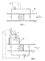
- Figure 1 shows flow inducing apparatus 10 comprising a liquid flow passage 4, an inlet electrode 1 extending across the passage, and an outlet electrode 2 also extending across the passage and located at a position downstream of the electrode 1.
- Arrow 6 indicates the direction of flow.
- Each of electrodes 1 and 2 is perforated so as to allow flow to pass through the electrodes.
- An electro-osmotic pump 5 is provided in the flow passage. This may be any of the pump types shown in WO 2004/007348 , for example.
- EO electro-osmotic
- These involve the use of a porous structure with a negative surface charge, giving rise to a layer of positive ions building up near the surface to screen the negative charge and maintain the charge balance. This creates an electric double layer.
- an electric field is applied, the positive ions are attracted towards the negatively charged electrode, and as they move they drag the surrounding liquid medium due to viscous forces. The liquid therefore is caused to move towards the negatively charged electrode.
- the surface charge may be positive, creating an electric double layer with negative ions outmost and available to be transported by the electric field.
- all potentials would be opposite to those described, in order to achieve flow in the directions shown.
- a voltage source V is provided between the electrodes 1 and 2, in order to make electrode 1 positive and electrode 2 negative.
- An ammeter 7 is provided in the circuit between the electrodes 1 and 2 in order the measure the current which flows.
- a control system 20 is provided to receive current data from the ammeter 7 and to provide a potential difference V between the electrodes 1 and 2.
- a voltage is applied such that electrode 1 is positive and electrode 2 is negative, giving rise to the EO pumping effect described above.
- the flow of liquid in the passage 4 takes place in the direction of arrow 6.
- the voltage V is adjusted, either manually or in accordance with a program in the control system 20, in order to obtain the desired pressure and flow rate.
- the current is logged electronically by ammeter 7.
- this pumping process some electrolysis of the liquid will take place, with the generation of H + ions at the positive electrode 1, which move to the negative electrode 2 as current carriers, driving the EO pump in the passage.
- the electrode 2 is made of a material such as palladium which is capable of absorbing hydrogen. Therefore the H + ions which arrive at electrode 2 combine with electrons to form hydrogen atoms which are then stored in electrode 2.
- the electrode is only capable of storing a certain amount of hydrogen, after which hydrogen gas would start to form.
- the electrode carries too much hydrogen, its metal lattice can expand irreversibly and so be damaged.
- the voltage V applied by control system 20 is reversed so that electrode 2 becomes positive and electrode 1 becomes negative. Hydrogen ions form at electrode 2 and are transported by the electric field towards electrode 1.
- the apparatus is either equipped with a check valve (not shown in the Figure), or the reverse voltage is set below a minimum value for flow to be generated for the EO pump 5 in use.
- the current is monitored by ammeter 7 during the regeneration operation.
- the regeneration phase will last until the same amount of charge (and hence of hydrogen) has been transported towards electrode 1 as was transported in the opposite direction during the preceding pumping phase. This is achieved by reversing the potentials until the product of current and time for the regeneration phase equals the corresponding amount for the pumping phase. In other words, the integrated current over the two periods is equal in absolute value and of opposite sign.
- the regeneration phase most of the current is carried by the H + ions generated from the hydrogen atoms stored in electrode 2.
- control system 20 is arranged to stop pumping at a time before a predetermined quantity of hydrogen has been absorbed. It may be arranged automatically to go into regeneration mode at this point, or it may give an audible and/or visible signal to a user. The control system may be set up to give an advance warning that regeneration will be required.
- the use of a regeneration phase following a pumping phase can thus avoid generation of hydrogen bubbles in the apparatus, which could otherwise accumulate and block the flow path.
- the regeneration scheme has the additional advantage that for many liquids the main electrochemical electrode reaction will be the stripping and absorption of hydrogen, instead of the decomposition of the liquid. Hence, the system will not only avoid formation of hydrogen bubbles at the negative electrode, but also of other gases at the positive electrode, such as oxygen for aqueous solutions and carbon dioxide for alcohol solutions. However, as liquid breakdown to generate hydrogen will still take place at a low rate, the electrodes will eventually be saturated with hydrogen, at which time the apparatus or the electrodes will normally have to be replaced.
- the electrodes 1 and 2 were made of perforated palladium foil each with a thickness of 25 micrometers.
- the apparatus measured the current at all times. Therefore, any variations in current were measured and hence taken account of to ensure that during the regeneration phase the same amount of charge is transferred between the electrodes in the opposite direction as that transferred during the pumping phase. It has been found that even if a constant voltage is applied the current may vary due to changes in the liquid properties or due to long term electrode degradation.
- the apparatus of Figure 1 is arranged to allow for such variations. In addition, it is sometimes desirable to operate the apparatus at varying pressures and flow rates and the apparatus of Figure 1 is able to take account of such variations.
- the apparatus may be a microfluidic pump, either automatically operated as part of a laboratory on a chip or a microfuel cell. It may be used as a manually operated laboratory pump.
- an alternative method of avoiding bubble formation at the electrodes, and hence in a flow path is provided.
- current reversal is not required and so they can provide a more continuous pumping mode. They can also avoid the need for a check valve system to rectify the flow during a regeneration phase. Electrode regeneration does however take place, and can normally do so at the same time as pumping, although regeneration after pumping is an option if desired.
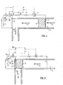
- FIG. 2 this is similar to Figure 1 to the extent that it shows flow inducing apparatus 10 having a flow passage 4, a perforated inlet electrode 1 extending across the passage, a perforated outlet electrode 2 extending across the passage and positioned downstream of electrode 1, and an EO pump 5 between the two electrodes.
- the inlet electrode 1 is made of an inert metal such as platinum, whilst the outlet electrode 2 is made of a metal capable of absorbing hydrogen such as palladium.
- An input voltage (V 1 ) is supplied to the electrodes 1 and 2 by a control system 20. When a voltage V 1 is applied a liquid flow in the direction of arrow 6 is generated.
- An ammeter 7 is provided to measure the current passing between the electrodes 1 and 2.
- the outlet electrode 2 extends out of the flow passage 4 in sealed manner and into a separate liquid filled chamber 10.
- the chamber 10 may contain an aqueous buffer solution.
- a third electrode 3 is provided to form a "bubbling" electrode.
- the chamber 3 is closed by a semi permeable membrane 15 which allows gas to escape in the direction of arrow 9.
- the membrane 15 may be a hydrophobic porous membrane such as Gore-Tex.
- An ammeter 8 is provided in the circuit between electrodes 2 and 3 in order to measure the current passing between those electrodes.
- the electronic data is fed to control system 20.
- a voltage V 2 is supplied to the circuit of electrodes 2 and 3 by the control system 20.
- the voltage V 1 is adjusted to obtain the desired flow rate for the given EO pump 5, while the current is monitored electronically by ammeter 7.
- the voltage V 2 is adjusted electronically by the control system 20 so that the current measured by ammeter 8 is always equal to that measured by the ammeter 7.
- the same number of hydrogen atoms absorbed by the electrode 2 during pumping will be removed from the part of the same electrode extending into the separate liquid filled chamber 10 by means of the third electrode 3.
- the electrode 3 is made of an inert metal, such as platinum, without an appreciable hydrogen absorption capability, hydrogen will form bubbles at this electrode, from which it can be vented. The hydrogen is transported along electrode 2 by diffusion. Electrode 2 will be at a potential which is negative relative to the potential of electrode 1 and positive relative to the potential of electrode 3.
- Figure 2 shows the separate chamber 10 only at one side of the passage 4.
- the chamber 10 could encircle the passage 4 or part of it, with the outlet electrode 2 extending out of the passage 4 at every point along the part or all of the circumference where the chamber 10 lies adjacent to the passage 4.
- the electrode 2 may be a circular disk with a greater diameter, extending into the separate chamber 3.
- the flow passage and the electrodes can also have other geometries, for example rectangular.
- the chamber 10 functions as a degassing chamber.
- the palladium electrode 2 will not be saturated with hydrogen even after long periods (as can happen in the two electrode setup due to continuing liquid electrolysis as a competing reaction to the hydrogen stripping and absorption). As new hydrogen is generated this will be removed in the separate chamber 10. However, the generation of other gases at the inlet electrode 1 may still occur. Often, this is less of a problem, for example if methanol is being pumped this has a large capacity for dissolving carbon dioxide which would otherwise be generated at the inlet electrode 1, so that bubble formation at this electrode can be avoided.
- the geometrical arrangement is modified to reduce the length of the diffusion path.
- this embodiment has the same arrangement of Figure 2 and so the description will not be repeated.
- the second electrode 2 does not extend across the passage and is not perforated.
- the second electrode 2 forms part of the wall of the passage 4 and is non-perforated.
- the electrode may be made of plate or foil and, as with the other embodiments, is made of a hydrogen absorbing metal such as palladium.
- a drawback of the embodiment of Figure 3 is that pumps requiring an even current distribution across the passage cross-section may not perform well with electrodes which do not extend into the passage.
- Figure 4 differs from Figure 3 in that an additional electrode is provided. This is intermediate electrode 2' which is provided downstream of the EO pump 5. Intermediate electrode 2' is perforated and extends across the passage 4. It is made of a hydrogen absorbing material such as palladium.
- the intermediate electrode 2' is arranged in series with inlet electrode 1, with the control system 20 applying a voltage V 1 which sets the potential of intermediate electrode 2' negative with respect to that of the potential of inlet electrode 1.
- Intermediate electrode 2' is arranged in series with the second electrode 2, with the control system 20 applying a voltage V 3 between these two electrodes such that electrode 2 has a negative potential relative to intermediate electrode 2'.
- An ammeter 12 is provided to measure the current flowing between the second electrode 2 and the intermediate electrode 2'.
- hydrogen ions are carried to intermediate electrode 2'. Because of the potential drop between electrode 2' and electrode 2, hydrogen is stripped from the electrode 2' and carried towards electrode 2 as hydrogen ions, where it is absorbed into the electrode. The hydrogen is then stripped from electrode 2 as hydrogen ions and carried to electrode 3 where it forms hydrogen which may be removed as hydrogen gas.
- This embodiment combines the advantage of that of Figure 2 of an outlet electrode (in this case, electrode 2') which extends across the passage and so provides a good current distribution, with the advantage of the embodiment of Figure 3 of a short diffusion path across the electrode 2 in the wall of the passage.
- Both electrodes 2' and 2 must be made of a hydrogen absorbing material such as palladium. As hydrogen stripping is associated with energy transfer, this scheme (with four electrodes) will consume more energy that the three electrode systems of Figures 2 or 3 .
- the voltage V 1 is adjusted to obtain the desired performance of the pump 5, while the voltages V 2 and V 3 are adjusted so that all currents are equal.
- the embodiment of Figure 4 may be modified such that intermediate electrode 2'is "flouting". It would not be in an external electrical circuit with electrode 1 or electrode 2, but would be isolated. There would still be a potential difference between electrodes 1 and 2 to drive the flow. Intermediate electrode 2' would still have the effect of providing a good current distribution across the passage. This modified embodiment would thus be more simple than that of Figure 4 , whilst providing similar advantages.
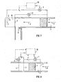
- Figure 5 shows an embodiment similar to that of Figure 3 and the description of the corresponding features will not be repeated.
- the difference is that the flow passage 4 includes a right angled bend.
- the electrode 2 forms part of the wall of the passage on the outside of the bend. This allows the electrode 2 to face the EO pump 5 and so provide a good electric field distribution for the pump. At the same time, the electrode 2 provides a short diffusion path for material e.g. hydrogen absorbed by the electrode.
- the voltage V 1 is adjusted to obtain the desired performance of the pump 5, while the voltage V 2 is adjusted so that the currents measured by the ammeters 7 and 8 are equal.
- fluid flows longitudinally in the direction of arrow 6, driven by the electric field and the pump.
- impervious electrode 2 When it reaches the impervious electrode 2 it is forced to change direction and so is diverted in the lateral direction shown by arrow 6a.
- Figure 6 The embodiment of Figure 6 is similar to that of Figure 5 in many respects and the description of the corresponding parts will not be repeated.
- the EO pump 5 is placed adjacent to the second electrode 2.
- the second electrode 2 has a non-perforated part 2a and a porous part 2b.
- the two parts are formed as two layers arranged face to face. The arrangement allows flow through the EO pump parallel to the electric field created by electrodes 1 and 2, in the direction of arrow 6, with the flow then blocked so as to cause the flow to be diverted perpendicular to the electric field in the direction of arrow 6a.
- the presence of the porous part 2b of the electrode permits the lateral flow through the porous part. This makes it possible for the EO pump 5 to be located directly adjacent to the electrode 2 without blocking the flow. For some types of pump, it is advantageous to be able to position the pump directly next to the outlet electrode.
- FIG. 7 The embodiment of Figure 7 is similar to that of Figure 5 in many respects and the description of the corresponding parts will not be repeated.
- a single voltage supply V 4 is used, connected with its two poles connected to the first electrode 1 and the third electrode 3.
- a voltmeter 11 is provided to measure the voltage between electrodes 1 and 2.
- the current will necessarily be the same between electrodes 1 and 2 as between electrodes 2 and 3, so the hydrogen removal functionality will be retained when hydrogen is the main positive current carrier in both the passage and the separate chamber.
- the voltage V 4 will be adjusted so as to adjust the voltage measured at voltmeter 11 and thereby obtain the desired flow and pressure.
- the current in the circuit can be measured by ammeter 7, in order to ensure that it does not become too high.
- the inlet 1 and degassing 3 electrodes need be connected to the voltage supply in the case of four (or more) electrodes e.g. provided along a passage.
- the voltage between the two electrodes defining the voltage across the pump must always be monitored and the voltage supply adjusted to get the desired voltage across the pump.
- the embodiment of Figure 8 differs from those of Figures 2-7 in that no separate degassing chamber 3 is provided.
- This embodiment has a flow passage 4 in which is provided an EO pump 5 through which liquid flows during pumping in the direction of arrow 6.
- An inlet electrode 1 is provided upstream of the pump 5, a second electrode 2 forming a first outlet electrode is provided at a first location downstream of the pump 5, and a third electrode 3 forming a second outlet electrode is provided downstream of the second electrode 2. All three electrodes extend across the flow passage to provide an even current distribution and are perforated to allow flow therethrough.
- the first and third electrodes are formed of non-hydrogen absorbing material, such as platinum, whilst the second electrode is formed of a material capable of absorbing hydrogen, such as palladium.
- the control system 20 applies a voltage V 1 between electrodes 1 and 2 and a voltage V 2 between electrodes 2 and 3.
- An ammeter 7 measures the current flowing between electrodes 1 and 2 and an ammeter 8 measures the current flowing between electrodes 2 and 3.
- the amount of hydrogen generated depends on the current, and the possibility for hydrogen to be dissolved depends on the available liquid volume, i.e. the flow. There therefore exists a current to flow ratio (a critical ratio) below which hydrogen generated at an electrode dissolves and so does not create bubbles.
- electrodes 1 and 2 When it is desired to increase the flow such that the current will be above the critical ratio, then electrodes 1 and 2 may be used. Hydrogen ions arriving at electrode 2 are absorbed into the material of the electrode. Then, when pumping using a current below the critical ratio, a potential difference may be applied between electrodes 2 and 3 such that the hydrogen absorbed into electrode 2 is stripped away as hydrogen ions which are carried to electrode 3, where they generate hydrogen which dissolves in the liquid. Hydrogen ions will thus arrive at electrode 3 as a result of the current flowing from electrode 1 through the pump and also as a result of hydrogen being stripped from electrode 2. Therefore the current flowing between electrodes 1 and 2 needs to be below the critical ratio with a sufficient margin to allow for the extra hydrogen which will be carried to electrode 3.
- An optional addition would be to provide a separate chamber into which electrode 2 would extend, increasing the capacity for hydrogen removal.
- the advantage of the Figure 8 embodiment is that by dissolving the hydrogen generated in the liquid it is possible to save energy and make the hydrogen absorbing material of electrode 2 last longer.
- the critical ratio can be calculated when the hydrogen absorbing capacity of the liquid is known.
- a commercial bubble detector can be connected to the control electronics, which will switch to the use of the hydrogen absorbing electrode to when required.
- the system will typically be controlled by standard low voltage electronics.
- the various power supplies symbol V
- ammeters A
- voltmeters represent just functionalities of electronic circuitry.
- the same circuit will typically adjust the voltage to obtain the desired liquid flow and pressure, while automatically taking care of the electrode regeneration.
- the current integration method assures that the pump can run for long periods without hydrogen saturation (resulting in bubble formation) for the case of a two electrode system, and indefinitely without bubbles for the three or more electrode system.
- the three (or more) electrode system also has the new feature that hydrogen will not accumulate slowly in the electrodes over time, hence the system will have a much longer bubble free lifetime, and the electrodes will also last much longer. In addition, there is no need for reversing the flow to regenerate the electrodes.
- the two electrode system has the advantage that the current can mainly be carried by hydrogen ions, which is removed from one electrode and absorbed by the other. After a short initial hydrogen generation period, the formation of other gases than hydrogen at the negative electrode (typically O 2 for aqueous and CO 2 for alcohols) will also be suppressed. For some liquids this can be important, although in other cases this brings no advantage as the other gas can be dissolved in the liquid (for example, methanol and ethanol have large capacities for absorbing CO 2 , while much smaller H 2 absorbance).
- gases typically O 2 for aqueous and CO 2 for alcohols
- Bubble free electrodes have great advantages for microfluidic devices, including lab-on-chip, micro-total-analysis-systems, micro fuel cells etc, as even small bubbles can block the flow path and disrupt the operation of such devices.
- the pump should be ideal for all kinds of electroosmotic / electrokinetic micropumps.
- the electrodes can be used in all kinds of devices where bubble formation can be a problem. It is not limited to microfluidic devices, but could be used in smaller (nanofludic) and larger devices.
- the regenerating operation is controlled so as to regenerate the second electrode by transferring via the second electrode an amount of charge equal to the amount measured during the induced charged particle motion operation, so as to cause ions to be removed from the second electrode and thereby regenerate that electrode.
Landscapes
- Engineering & Computer Science (AREA)
- Mechanical Engineering (AREA)
- General Engineering & Computer Science (AREA)
- Physical Or Chemical Processes And Apparatus (AREA)
- Automatic Analysis And Handling Materials Therefor (AREA)
- Fuel Cell (AREA)
- Investigating Or Analysing Biological Materials (AREA)
Applications Claiming Priority (2)
| Application Number | Priority Date | Filing Date | Title |
|---|---|---|---|
| GBGB0903134.5A GB0903134D0 (en) | 2009-02-24 | 2009-02-24 | Charged particle motion inducing apparatus |
| PCT/GB2010/000331 WO2010097581A2 (en) | 2009-02-24 | 2010-02-24 | Charged particle motion inducing apparatus |
Publications (2)
| Publication Number | Publication Date |
|---|---|
| EP2401809A2 EP2401809A2 (en) | 2012-01-04 |
| EP2401809B1 true EP2401809B1 (en) | 2016-01-06 |
Family
ID=40565645
Family Applications (1)
| Application Number | Title | Priority Date | Filing Date |
|---|---|---|---|
| EP10712742.5A Not-in-force EP2401809B1 (en) | 2009-02-24 | 2010-02-24 | Charged particle motion inducing apparatus |
Country Status (8)
| Country | Link |
|---|---|
| US (1) | US20120024702A1 (enExample) |
| EP (1) | EP2401809B1 (enExample) |
| JP (1) | JP5631338B2 (enExample) |
| CN (1) | CN102428274B (enExample) |
| BR (1) | BRPI1007807A2 (enExample) |
| CA (1) | CA2753463A1 (enExample) |
| GB (1) | GB0903134D0 (enExample) |
| WO (1) | WO2010097581A2 (enExample) |
Families Citing this family (6)
| Publication number | Priority date | Publication date | Assignee | Title |
|---|---|---|---|---|
| JP2811956B2 (ja) | 1990-11-20 | 1998-10-15 | 三菱マテリアル株式会社 | 冶金炉の底抜き装置 |
| GB201408472D0 (en) | 2014-05-13 | 2014-06-25 | Osmotex Ag | Electroosmotic membrane |
| US10202695B2 (en) * | 2015-05-21 | 2019-02-12 | Palo Alto Research Center Incorporated | Photoelectrolysis system and method |
| CN111229346B (zh) * | 2020-02-11 | 2022-02-01 | 中山大学 | 一种基于动态涂层的电渗微泵系统及其应用 |
| EP4410407A1 (en) * | 2023-02-01 | 2024-08-07 | Centre National de la Recherche Scientifique | Reverse electro-osmotic filtration exploiting nanofluidic transport through asymmetric membrane |
| IL322425A (en) * | 2023-02-01 | 2025-09-01 | Centre Nat Rech Scient | Reverse electro-osmotic filtration utilizing nanofluidic transport through an asymmetric membrane |
Family Cites Families (13)
| Publication number | Priority date | Publication date | Assignee | Title |
|---|---|---|---|---|
| GB9225098D0 (en) * | 1992-12-01 | 1993-01-20 | Coffee Ronald A | Charged droplet spray mixer |
| JPH09309429A (ja) * | 1996-05-24 | 1997-12-02 | Akebono Brake Res & Dev Center Ltd | ブレーキ制御装置 |
| WO1999049306A1 (en) * | 1998-03-20 | 1999-09-30 | Sarnoff Corporation | Balanced asymmetric electronic pulse patterns for operating electrode-based pumps |
| US6290839B1 (en) * | 1998-06-23 | 2001-09-18 | Clinical Micro Sensors, Inc. | Systems for electrophoretic transport and detection of analytes |
| GB0020487D0 (en) * | 2000-08-18 | 2000-10-11 | Aea Technology Plc | Moving liquid into and along micro-fluidic channels |
| US20020185947A1 (en) * | 2001-06-11 | 2002-12-12 | Schulte Donald W. | Micro ion pump for a low-pressure microdevice microenclosure |
| NO20023398D0 (no) * | 2002-07-15 | 2002-07-15 | Osmotex As | Anordning og fremgangsmåte for transport av v¶ske gjennom materialer |
| US7235164B2 (en) * | 2002-10-18 | 2007-06-26 | Eksigent Technologies, Llc | Electrokinetic pump having capacitive electrodes |
| US6872292B2 (en) * | 2003-01-28 | 2005-03-29 | Microlin, L.C. | Voltage modulation of advanced electrochemical delivery system |
| US7258777B2 (en) * | 2003-07-21 | 2007-08-21 | Eksigent Technologies Llc | Bridges for electroosmotic flow systems |
| DE102006004887B4 (de) * | 2006-02-03 | 2010-07-22 | Karlsruher Institut für Technologie | Vorrichtung zur Erzeugung von Flüssigkeitsströmungen, Verfahren zu ihrer Herstellung und zu ihrem Betrieb sowie ihre Verwendung |
| JP5082979B2 (ja) * | 2008-03-27 | 2012-11-28 | カシオ計算機株式会社 | 電気浸透流ポンプの制御方法及び制御装置並びに燃料電池システム |
| JP2009264786A (ja) * | 2008-04-22 | 2009-11-12 | Canon Inc | 界面動電装置 |
-
2009
- 2009-02-24 GB GBGB0903134.5A patent/GB0903134D0/en not_active Ceased
-
2010
- 2010-02-24 US US13/203,205 patent/US20120024702A1/en not_active Abandoned
- 2010-02-24 EP EP10712742.5A patent/EP2401809B1/en not_active Not-in-force
- 2010-02-24 BR BRPI1007807A patent/BRPI1007807A2/pt not_active IP Right Cessation
- 2010-02-24 JP JP2011551518A patent/JP5631338B2/ja not_active Expired - Fee Related
- 2010-02-24 CA CA2753463A patent/CA2753463A1/en not_active Abandoned
- 2010-02-24 CN CN201080017713.9A patent/CN102428274B/zh not_active Expired - Fee Related
- 2010-02-24 WO PCT/GB2010/000331 patent/WO2010097581A2/en not_active Ceased
Also Published As
| Publication number | Publication date |
|---|---|
| WO2010097581A2 (en) | 2010-09-02 |
| US20120024702A1 (en) | 2012-02-02 |
| CN102428274B (zh) | 2015-04-22 |
| BRPI1007807A2 (pt) | 2016-02-23 |
| CN102428274A (zh) | 2012-04-25 |
| EP2401809A2 (en) | 2012-01-04 |
| JP5631338B2 (ja) | 2014-11-26 |
| WO2010097581A3 (en) | 2011-11-17 |
| GB0903134D0 (en) | 2009-04-08 |
| JP2012518799A (ja) | 2012-08-16 |
| CA2753463A1 (en) | 2010-09-02 |
Similar Documents
| Publication | Publication Date | Title |
|---|---|---|
| US7399398B2 (en) | Variable potential electrokinetic devices | |
| Wang et al. | Electroosmotic pumps and their applications in microfluidic systems | |
| EP2401809B1 (en) | Charged particle motion inducing apparatus | |
| Cho et al. | Overlimiting current through ion concentration polarization layer: hydrodynamic convection effects | |
| US6287440B1 (en) | Method for eliminating gas blocking in electrokinetic pumping systems | |
| EP2242926B1 (en) | Electro-osmotic pump | |
| Morf et al. | Partial electroosmotic pumping in complex capillary systems: Part 1: Principles and general theoretical approach | |
| Homsy et al. | A high current density DC magnetohydrodynamic (MHD) micropump | |
| Guenat et al. | Partial electroosmotic pumping in complex capillary systems: Part 2: Fabrication and application of a micro total analysis system (μTAS) suited for continuous volumetric nanotitrations | |
| US7695603B2 (en) | Electroosmotic flow controller | |
| Solignac et al. | Pressure pulse injection: a powerful alternative to electrokinetic sample loading in electrophoresis microchips | |
| Kneller et al. | AC electroosmotic pumping in nanofluidic funnels | |
| KR20110081148A (ko) | 전기화학적 구동 펌프 | |
| Kim et al. | Quantifying the pH shift induced by selective anodic electrochemical reactions in the ion concentration polarization phenomenon | |
| Contento et al. | Tunable electrochemical pH modulation in a microchannel monitored via the proton-coupled electro-oxidation of hydroquinone | |
| US20030086333A1 (en) | Electrohydrodynamic mixing on microfabricated devices | |
| CN102886236B (zh) | 一种纳米尺度的微通道内流体的驱动方法 | |
| Pi et al. | 3D printed micro/nanofluidic preconcentrator for charged sample based on ion concentration polarization | |
| Ehlert et al. | Electrohydrodynamics around single ion-permselective glass beads fixed in a microfluidic device | |
| Lin et al. | Toward orientation-independent design for gas recombination in closed-loop electroosmotic pumps | |
| Mishchuk et al. | Microfluidic pump based on the phenomenon of electroosmosis of the second kind | |
| Wang et al. | Low-voltage electroosmotic pumping using polyethylene terephthalate track-etched membrane | |
| KR100767277B1 (ko) | 마이크로채널에서 유체의 혼합방법 및 시스템 | |
| Peramune et al. | Ion concentration polarization focusing at a millimeter-scale microbead junction: towards higher volumetric throughput | |
| Choi et al. | Ion transportation control in nanofluidics through geometrically controlled nanoparticle assembly |
Legal Events
| Date | Code | Title | Description |
|---|---|---|---|
| PUAI | Public reference made under article 153(3) epc to a published international application that has entered the european phase |
Free format text: ORIGINAL CODE: 0009012 |
|
| 17P | Request for examination filed |
Effective date: 20110923 |
|
| AK | Designated contracting states |
Kind code of ref document: A2 Designated state(s): AT BE BG CH CY CZ DE DK EE ES FI FR GB GR HR HU IE IS IT LI LT LU LV MC MK MT NL NO PL PT RO SE SI SK SM TR |
|
| DAX | Request for extension of the european patent (deleted) | ||
| 17Q | First examination report despatched |
Effective date: 20130215 |
|
| GRAP | Despatch of communication of intention to grant a patent |
Free format text: ORIGINAL CODE: EPIDOSNIGR1 |
|
| INTG | Intention to grant announced |
Effective date: 20150624 |
|
| GRAS | Grant fee paid |
Free format text: ORIGINAL CODE: EPIDOSNIGR3 |
|
| GRAA | (expected) grant |
Free format text: ORIGINAL CODE: 0009210 |
|
| AK | Designated contracting states |
Kind code of ref document: B1 Designated state(s): AT BE BG CH CY CZ DE DK EE ES FI FR GB GR HR HU IE IS IT LI LT LU LV MC MK MT NL NO PL PT RO SE SI SK SM TR |
|
| REG | Reference to a national code |
Ref country code: GB Ref legal event code: FG4D |
|
| REG | Reference to a national code |
Ref country code: CH Ref legal event code: EP |
|
| REG | Reference to a national code |
Ref country code: IE Ref legal event code: FG4D |
|
| REG | Reference to a national code |
Ref country code: AT Ref legal event code: REF Ref document number: 769630 Country of ref document: AT Kind code of ref document: T Effective date: 20160215 |
|
| REG | Reference to a national code |
Ref country code: DE Ref legal event code: R096 Ref document number: 602010029889 Country of ref document: DE |
|
| REG | Reference to a national code |
Ref country code: LT Ref legal event code: MG4D |
|
| REG | Reference to a national code |
Ref country code: NL Ref legal event code: MP Effective date: 20160106 |
|
| REG | Reference to a national code |
Ref country code: AT Ref legal event code: MK05 Ref document number: 769630 Country of ref document: AT Kind code of ref document: T Effective date: 20160106 |
|
| PG25 | Lapsed in a contracting state [announced via postgrant information from national office to epo] |
Ref country code: BE Free format text: LAPSE BECAUSE OF NON-PAYMENT OF DUE FEES Effective date: 20160229 |
|
| PG25 | Lapsed in a contracting state [announced via postgrant information from national office to epo] |
Ref country code: NL Free format text: LAPSE BECAUSE OF FAILURE TO SUBMIT A TRANSLATION OF THE DESCRIPTION OR TO PAY THE FEE WITHIN THE PRESCRIBED TIME-LIMIT Effective date: 20160106 |
|
| PG25 | Lapsed in a contracting state [announced via postgrant information from national office to epo] |
Ref country code: HR Free format text: LAPSE BECAUSE OF FAILURE TO SUBMIT A TRANSLATION OF THE DESCRIPTION OR TO PAY THE FEE WITHIN THE PRESCRIBED TIME-LIMIT Effective date: 20160106 Ref country code: IT Free format text: LAPSE BECAUSE OF FAILURE TO SUBMIT A TRANSLATION OF THE DESCRIPTION OR TO PAY THE FEE WITHIN THE PRESCRIBED TIME-LIMIT Effective date: 20160106 Ref country code: ES Free format text: LAPSE BECAUSE OF FAILURE TO SUBMIT A TRANSLATION OF THE DESCRIPTION OR TO PAY THE FEE WITHIN THE PRESCRIBED TIME-LIMIT Effective date: 20160106 Ref country code: NO Free format text: LAPSE BECAUSE OF FAILURE TO SUBMIT A TRANSLATION OF THE DESCRIPTION OR TO PAY THE FEE WITHIN THE PRESCRIBED TIME-LIMIT Effective date: 20160406 Ref country code: FI Free format text: LAPSE BECAUSE OF FAILURE TO SUBMIT A TRANSLATION OF THE DESCRIPTION OR TO PAY THE FEE WITHIN THE PRESCRIBED TIME-LIMIT Effective date: 20160106 Ref country code: GR Free format text: LAPSE BECAUSE OF FAILURE TO SUBMIT A TRANSLATION OF THE DESCRIPTION OR TO PAY THE FEE WITHIN THE PRESCRIBED TIME-LIMIT Effective date: 20160407 |
|
| PG25 | Lapsed in a contracting state [announced via postgrant information from national office to epo] |
Ref country code: IS Free format text: LAPSE BECAUSE OF FAILURE TO SUBMIT A TRANSLATION OF THE DESCRIPTION OR TO PAY THE FEE WITHIN THE PRESCRIBED TIME-LIMIT Effective date: 20160506 Ref country code: AT Free format text: LAPSE BECAUSE OF FAILURE TO SUBMIT A TRANSLATION OF THE DESCRIPTION OR TO PAY THE FEE WITHIN THE PRESCRIBED TIME-LIMIT Effective date: 20160106 Ref country code: PL Free format text: LAPSE BECAUSE OF FAILURE TO SUBMIT A TRANSLATION OF THE DESCRIPTION OR TO PAY THE FEE WITHIN THE PRESCRIBED TIME-LIMIT Effective date: 20160106 Ref country code: SE Free format text: LAPSE BECAUSE OF FAILURE TO SUBMIT A TRANSLATION OF THE DESCRIPTION OR TO PAY THE FEE WITHIN THE PRESCRIBED TIME-LIMIT Effective date: 20160106 Ref country code: LV Free format text: LAPSE BECAUSE OF FAILURE TO SUBMIT A TRANSLATION OF THE DESCRIPTION OR TO PAY THE FEE WITHIN THE PRESCRIBED TIME-LIMIT Effective date: 20160106 Ref country code: PT Free format text: LAPSE BECAUSE OF FAILURE TO SUBMIT A TRANSLATION OF THE DESCRIPTION OR TO PAY THE FEE WITHIN THE PRESCRIBED TIME-LIMIT Effective date: 20160506 Ref country code: LT Free format text: LAPSE BECAUSE OF FAILURE TO SUBMIT A TRANSLATION OF THE DESCRIPTION OR TO PAY THE FEE WITHIN THE PRESCRIBED TIME-LIMIT Effective date: 20160106 |
|
| REG | Reference to a national code |
Ref country code: DE Ref legal event code: R119 Ref document number: 602010029889 Country of ref document: DE |
|
| PG25 | Lapsed in a contracting state [announced via postgrant information from national office to epo] |
Ref country code: DK Free format text: LAPSE BECAUSE OF FAILURE TO SUBMIT A TRANSLATION OF THE DESCRIPTION OR TO PAY THE FEE WITHIN THE PRESCRIBED TIME-LIMIT Effective date: 20160106 Ref country code: MC Free format text: LAPSE BECAUSE OF FAILURE TO SUBMIT A TRANSLATION OF THE DESCRIPTION OR TO PAY THE FEE WITHIN THE PRESCRIBED TIME-LIMIT Effective date: 20160106 Ref country code: EE Free format text: LAPSE BECAUSE OF FAILURE TO SUBMIT A TRANSLATION OF THE DESCRIPTION OR TO PAY THE FEE WITHIN THE PRESCRIBED TIME-LIMIT Effective date: 20160106 |
|
| PLBE | No opposition filed within time limit |
Free format text: ORIGINAL CODE: 0009261 |
|
| STAA | Information on the status of an ep patent application or granted ep patent |
Free format text: STATUS: NO OPPOSITION FILED WITHIN TIME LIMIT |
|
| REG | Reference to a national code |
Ref country code: FR Ref legal event code: ST Effective date: 20161028 |
|
| PG25 | Lapsed in a contracting state [announced via postgrant information from national office to epo] |
Ref country code: SM Free format text: LAPSE BECAUSE OF FAILURE TO SUBMIT A TRANSLATION OF THE DESCRIPTION OR TO PAY THE FEE WITHIN THE PRESCRIBED TIME-LIMIT Effective date: 20160106 Ref country code: CZ Free format text: LAPSE BECAUSE OF FAILURE TO SUBMIT A TRANSLATION OF THE DESCRIPTION OR TO PAY THE FEE WITHIN THE PRESCRIBED TIME-LIMIT Effective date: 20160106 Ref country code: RO Free format text: LAPSE BECAUSE OF FAILURE TO SUBMIT A TRANSLATION OF THE DESCRIPTION OR TO PAY THE FEE WITHIN THE PRESCRIBED TIME-LIMIT Effective date: 20160106 Ref country code: SK Free format text: LAPSE BECAUSE OF FAILURE TO SUBMIT A TRANSLATION OF THE DESCRIPTION OR TO PAY THE FEE WITHIN THE PRESCRIBED TIME-LIMIT Effective date: 20160106 |
|
| 26N | No opposition filed |
Effective date: 20161007 |
|
| GBPC | Gb: european patent ceased through non-payment of renewal fee |
Effective date: 20160406 |
|
| PG25 | Lapsed in a contracting state [announced via postgrant information from national office to epo] |
Ref country code: BE Free format text: LAPSE BECAUSE OF FAILURE TO SUBMIT A TRANSLATION OF THE DESCRIPTION OR TO PAY THE FEE WITHIN THE PRESCRIBED TIME-LIMIT Effective date: 20160106 |
|
| PG25 | Lapsed in a contracting state [announced via postgrant information from national office to epo] |
Ref country code: GB Free format text: LAPSE BECAUSE OF NON-PAYMENT OF DUE FEES Effective date: 20160406 Ref country code: FR Free format text: LAPSE BECAUSE OF NON-PAYMENT OF DUE FEES Effective date: 20160307 Ref country code: DE Free format text: LAPSE BECAUSE OF NON-PAYMENT OF DUE FEES Effective date: 20160901 |
|
| PGFP | Annual fee paid to national office [announced via postgrant information from national office to epo] |
Ref country code: IE Payment date: 20161005 Year of fee payment: 7 |
|
| PG25 | Lapsed in a contracting state [announced via postgrant information from national office to epo] |
Ref country code: SI Free format text: LAPSE BECAUSE OF FAILURE TO SUBMIT A TRANSLATION OF THE DESCRIPTION OR TO PAY THE FEE WITHIN THE PRESCRIBED TIME-LIMIT Effective date: 20160106 Ref country code: BG Free format text: LAPSE BECAUSE OF FAILURE TO SUBMIT A TRANSLATION OF THE DESCRIPTION OR TO PAY THE FEE WITHIN THE PRESCRIBED TIME-LIMIT Effective date: 20160406 |
|
| PGFP | Annual fee paid to national office [announced via postgrant information from national office to epo] |
Ref country code: CH Payment date: 20170119 Year of fee payment: 8 |
|
| PG25 | Lapsed in a contracting state [announced via postgrant information from national office to epo] |
Ref country code: MT Free format text: LAPSE BECAUSE OF FAILURE TO SUBMIT A TRANSLATION OF THE DESCRIPTION OR TO PAY THE FEE WITHIN THE PRESCRIBED TIME-LIMIT Effective date: 20160106 |
|
| PG25 | Lapsed in a contracting state [announced via postgrant information from national office to epo] |
Ref country code: CY Free format text: LAPSE BECAUSE OF FAILURE TO SUBMIT A TRANSLATION OF THE DESCRIPTION OR TO PAY THE FEE WITHIN THE PRESCRIBED TIME-LIMIT Effective date: 20160106 Ref country code: HU Free format text: LAPSE BECAUSE OF FAILURE TO SUBMIT A TRANSLATION OF THE DESCRIPTION OR TO PAY THE FEE WITHIN THE PRESCRIBED TIME-LIMIT; INVALID AB INITIO Effective date: 20100224 |
|
| PG25 | Lapsed in a contracting state [announced via postgrant information from national office to epo] |
Ref country code: MK Free format text: LAPSE BECAUSE OF FAILURE TO SUBMIT A TRANSLATION OF THE DESCRIPTION OR TO PAY THE FEE WITHIN THE PRESCRIBED TIME-LIMIT Effective date: 20160106 Ref country code: MT Free format text: LAPSE BECAUSE OF FAILURE TO SUBMIT A TRANSLATION OF THE DESCRIPTION OR TO PAY THE FEE WITHIN THE PRESCRIBED TIME-LIMIT Effective date: 20160229 Ref country code: LU Free format text: LAPSE BECAUSE OF NON-PAYMENT OF DUE FEES Effective date: 20160224 Ref country code: TR Free format text: LAPSE BECAUSE OF FAILURE TO SUBMIT A TRANSLATION OF THE DESCRIPTION OR TO PAY THE FEE WITHIN THE PRESCRIBED TIME-LIMIT Effective date: 20160106 |
|
| REG | Reference to a national code |
Ref country code: CH Ref legal event code: PL |
|
| REG | Reference to a national code |
Ref country code: IE Ref legal event code: MM4A |
|
| PG25 | Lapsed in a contracting state [announced via postgrant information from national office to epo] |
Ref country code: CH Free format text: LAPSE BECAUSE OF NON-PAYMENT OF DUE FEES Effective date: 20180228 Ref country code: LI Free format text: LAPSE BECAUSE OF NON-PAYMENT OF DUE FEES Effective date: 20180228 |
|
| PG25 | Lapsed in a contracting state [announced via postgrant information from national office to epo] |
Ref country code: IE Free format text: LAPSE BECAUSE OF NON-PAYMENT OF DUE FEES Effective date: 20180224 |