EP2399533B1 - System zum Entfernen einer Substanz aus einem Knochen - Google Patents
System zum Entfernen einer Substanz aus einem Knochen Download PDFInfo
- Publication number
- EP2399533B1 EP2399533B1 EP11250603.5A EP11250603A EP2399533B1 EP 2399533 B1 EP2399533 B1 EP 2399533B1 EP 11250603 A EP11250603 A EP 11250603A EP 2399533 B1 EP2399533 B1 EP 2399533B1
- Authority
- EP
- European Patent Office
- Prior art keywords
- insert
- bone
- bone screw
- screw
- fenestrations
- Prior art date
- Legal status (The legal status is an assumption and is not a legal conclusion. Google has not performed a legal analysis and makes no representation as to the accuracy of the status listed.)
- Active
Links
Images

















Classifications
-
- A—HUMAN NECESSITIES
- A61—MEDICAL OR VETERINARY SCIENCE; HYGIENE
- A61B—DIAGNOSIS; SURGERY; IDENTIFICATION
- A61B17/00—Surgical instruments, devices or methods
- A61B17/56—Surgical instruments or methods for treatment of bones or joints; Devices specially adapted therefor
- A61B17/58—Surgical instruments or methods for treatment of bones or joints; Devices specially adapted therefor for osteosynthesis, e.g. bone plates, screws or setting implements
- A61B17/68—Internal fixation devices, including fasteners and spinal fixators, even if a part thereof projects from the skin
- A61B17/84—Fasteners therefor or fasteners being internal fixation devices
- A61B17/86—Pins or screws or threaded wires; nuts therefor
- A61B17/864—Pins or screws or threaded wires; nuts therefor hollow, e.g. with socket or cannulated
-
- A—HUMAN NECESSITIES
- A61—MEDICAL OR VETERINARY SCIENCE; HYGIENE
- A61B—DIAGNOSIS; SURGERY; IDENTIFICATION
- A61B17/00—Surgical instruments, devices or methods
- A61B17/34—Trocars; Puncturing needles
- A61B17/3472—Trocars; Puncturing needles for bones, e.g. intraosseus injections
-
- A—HUMAN NECESSITIES
- A61—MEDICAL OR VETERINARY SCIENCE; HYGIENE
- A61B—DIAGNOSIS; SURGERY; IDENTIFICATION
- A61B17/00—Surgical instruments, devices or methods
- A61B17/56—Surgical instruments or methods for treatment of bones or joints; Devices specially adapted therefor
- A61B17/58—Surgical instruments or methods for treatment of bones or joints; Devices specially adapted therefor for osteosynthesis, e.g. bone plates, screws or setting implements
- A61B17/68—Internal fixation devices, including fasteners and spinal fixators, even if a part thereof projects from the skin
- A61B17/70—Spinal positioners or stabilisers, e.g. stabilisers comprising fluid filler in an implant
- A61B17/7061—Spinal positioners or stabilisers, e.g. stabilisers comprising fluid filler in an implant for stabilising vertebrae or discs by improving the condition of their tissues, e.g. using implanted medication or fluid exchange
-
- A—HUMAN NECESSITIES
- A61—MEDICAL OR VETERINARY SCIENCE; HYGIENE
- A61B—DIAGNOSIS; SURGERY; IDENTIFICATION
- A61B17/00—Surgical instruments, devices or methods
- A61B17/56—Surgical instruments or methods for treatment of bones or joints; Devices specially adapted therefor
- A61B17/58—Surgical instruments or methods for treatment of bones or joints; Devices specially adapted therefor for osteosynthesis, e.g. bone plates, screws or setting implements
- A61B17/68—Internal fixation devices, including fasteners and spinal fixators, even if a part thereof projects from the skin
- A61B17/70—Spinal positioners or stabilisers, e.g. stabilisers comprising fluid filler in an implant
- A61B17/7097—Stabilisers comprising fluid filler in an implant, e.g. balloon; devices for inserting or filling such implants
- A61B17/7098—Stabilisers comprising fluid filler in an implant, e.g. balloon; devices for inserting or filling such implants wherein the implant is permeable or has openings, e.g. fenestrated screw
-
- A—HUMAN NECESSITIES
- A61—MEDICAL OR VETERINARY SCIENCE; HYGIENE
- A61B—DIAGNOSIS; SURGERY; IDENTIFICATION
- A61B17/00—Surgical instruments, devices or methods
- A61B17/56—Surgical instruments or methods for treatment of bones or joints; Devices specially adapted therefor
- A61B17/58—Surgical instruments or methods for treatment of bones or joints; Devices specially adapted therefor for osteosynthesis, e.g. bone plates, screws or setting implements
- A61B17/68—Internal fixation devices, including fasteners and spinal fixators, even if a part thereof projects from the skin
- A61B17/84—Fasteners therefor or fasteners being internal fixation devices
- A61B17/86—Pins or screws or threaded wires; nuts therefor
- A61B17/866—Material or manufacture
-
- A—HUMAN NECESSITIES
- A61—MEDICAL OR VETERINARY SCIENCE; HYGIENE
- A61B—DIAGNOSIS; SURGERY; IDENTIFICATION
- A61B17/00—Surgical instruments, devices or methods
- A61B17/56—Surgical instruments or methods for treatment of bones or joints; Devices specially adapted therefor
- A61B17/58—Surgical instruments or methods for treatment of bones or joints; Devices specially adapted therefor for osteosynthesis, e.g. bone plates, screws or setting implements
- A61B17/68—Internal fixation devices, including fasteners and spinal fixators, even if a part thereof projects from the skin
- A61B17/84—Fasteners therefor or fasteners being internal fixation devices
- A61B17/86—Pins or screws or threaded wires; nuts therefor
- A61B17/8685—Pins or screws or threaded wires; nuts therefor comprising multiple separate parts
-
- A—HUMAN NECESSITIES
- A61—MEDICAL OR VETERINARY SCIENCE; HYGIENE
- A61B—DIAGNOSIS; SURGERY; IDENTIFICATION
- A61B17/00—Surgical instruments, devices or methods
- A61B17/56—Surgical instruments or methods for treatment of bones or joints; Devices specially adapted therefor
- A61B17/58—Surgical instruments or methods for treatment of bones or joints; Devices specially adapted therefor for osteosynthesis, e.g. bone plates, screws or setting implements
- A61B17/88—Osteosynthesis instruments; Methods or means for implanting or extracting internal or external fixation devices
- A61B17/8802—Equipment for handling bone cement or other fluid fillers
- A61B17/8805—Equipment for handling bone cement or other fluid fillers for introducing fluid filler into bone or extracting it
- A61B17/8819—Equipment for handling bone cement or other fluid fillers for introducing fluid filler into bone or extracting it characterised by the introducer proximal part, e.g. cannula handle, or by parts which are inserted inside each other, e.g. stylet and cannula
-
- A—HUMAN NECESSITIES
- A61—MEDICAL OR VETERINARY SCIENCE; HYGIENE
- A61B—DIAGNOSIS; SURGERY; IDENTIFICATION
- A61B17/00—Surgical instruments, devices or methods
- A61B17/56—Surgical instruments or methods for treatment of bones or joints; Devices specially adapted therefor
- A61B17/58—Surgical instruments or methods for treatment of bones or joints; Devices specially adapted therefor for osteosynthesis, e.g. bone plates, screws or setting implements
- A61B17/88—Osteosynthesis instruments; Methods or means for implanting or extracting internal or external fixation devices
- A61B17/8802—Equipment for handling bone cement or other fluid fillers
- A61B17/8833—Osteosynthesis tools specially adapted for handling bone cement or fluid fillers; Means for supplying bone cement or fluid fillers to introducing tools, e.g. cartridge handling means
- A61B17/8836—Osteosynthesis tools specially adapted for handling bone cement or fluid fillers; Means for supplying bone cement or fluid fillers to introducing tools, e.g. cartridge handling means for heating, cooling or curing of bone cement or fluid fillers
-
- A—HUMAN NECESSITIES
- A61—MEDICAL OR VETERINARY SCIENCE; HYGIENE
- A61B—DIAGNOSIS; SURGERY; IDENTIFICATION
- A61B17/00—Surgical instruments, devices or methods
- A61B17/56—Surgical instruments or methods for treatment of bones or joints; Devices specially adapted therefor
- A61B17/58—Surgical instruments or methods for treatment of bones or joints; Devices specially adapted therefor for osteosynthesis, e.g. bone plates, screws or setting implements
- A61B17/88—Osteosynthesis instruments; Methods or means for implanting or extracting internal or external fixation devices
- A61B17/8802—Equipment for handling bone cement or other fluid fillers
- A61B17/8841—Tools specially adapted to engage a prosthesis
-
- A—HUMAN NECESSITIES
- A61—MEDICAL OR VETERINARY SCIENCE; HYGIENE
- A61M—DEVICES FOR INTRODUCING MEDIA INTO, OR ONTO, THE BODY; DEVICES FOR TRANSDUCING BODY MEDIA OR FOR TAKING MEDIA FROM THE BODY; DEVICES FOR PRODUCING OR ENDING SLEEP OR STUPOR
- A61M37/00—Other apparatus for introducing media into the body; Percutany, i.e. introducing medicines into the body by diffusion through the skin
-
- A—HUMAN NECESSITIES
- A61—MEDICAL OR VETERINARY SCIENCE; HYGIENE
- A61B—DIAGNOSIS; SURGERY; IDENTIFICATION
- A61B17/00—Surgical instruments, devices or methods
- A61B17/56—Surgical instruments or methods for treatment of bones or joints; Devices specially adapted therefor
- A61B17/58—Surgical instruments or methods for treatment of bones or joints; Devices specially adapted therefor for osteosynthesis, e.g. bone plates, screws or setting implements
- A61B17/68—Internal fixation devices, including fasteners and spinal fixators, even if a part thereof projects from the skin
- A61B17/72—Intramedullary devices, e.g. pins or nails
-
- A—HUMAN NECESSITIES
- A61—MEDICAL OR VETERINARY SCIENCE; HYGIENE
- A61B—DIAGNOSIS; SURGERY; IDENTIFICATION
- A61B17/00—Surgical instruments, devices or methods
- A61B17/56—Surgical instruments or methods for treatment of bones or joints; Devices specially adapted therefor
- A61B17/58—Surgical instruments or methods for treatment of bones or joints; Devices specially adapted therefor for osteosynthesis, e.g. bone plates, screws or setting implements
- A61B17/68—Internal fixation devices, including fasteners and spinal fixators, even if a part thereof projects from the skin
- A61B17/72—Intramedullary devices, e.g. pins or nails
- A61B17/7233—Intramedullary devices, e.g. pins or nails with special means of locking the nail to the bone
- A61B17/7258—Intramedullary devices, e.g. pins or nails with special means of locking the nail to the bone with laterally expanding parts, e.g. for gripping the bone
-
- A—HUMAN NECESSITIES
- A61—MEDICAL OR VETERINARY SCIENCE; HYGIENE
- A61B—DIAGNOSIS; SURGERY; IDENTIFICATION
- A61B17/00—Surgical instruments, devices or methods
- A61B17/56—Surgical instruments or methods for treatment of bones or joints; Devices specially adapted therefor
- A61B17/58—Surgical instruments or methods for treatment of bones or joints; Devices specially adapted therefor for osteosynthesis, e.g. bone plates, screws or setting implements
- A61B17/68—Internal fixation devices, including fasteners and spinal fixators, even if a part thereof projects from the skin
- A61B17/74—Devices for the head or neck or trochanter of the femur
- A61B17/742—Devices for the head or neck or trochanter of the femur having one or more longitudinal elements oriented along or parallel to the axis of the neck
- A61B17/744—Devices for the head or neck or trochanter of the femur having one or more longitudinal elements oriented along or parallel to the axis of the neck the longitudinal elements coupled to an intramedullary nail
-
- A—HUMAN NECESSITIES
- A61—MEDICAL OR VETERINARY SCIENCE; HYGIENE
- A61B—DIAGNOSIS; SURGERY; IDENTIFICATION
- A61B17/00—Surgical instruments, devices or methods
- A61B17/56—Surgical instruments or methods for treatment of bones or joints; Devices specially adapted therefor
- A61B17/58—Surgical instruments or methods for treatment of bones or joints; Devices specially adapted therefor for osteosynthesis, e.g. bone plates, screws or setting implements
- A61B17/88—Osteosynthesis instruments; Methods or means for implanting or extracting internal or external fixation devices
- A61B17/8802—Equipment for handling bone cement or other fluid fillers
- A61B17/8833—Osteosynthesis tools specially adapted for handling bone cement or fluid fillers; Means for supplying bone cement or fluid fillers to introducing tools, e.g. cartridge handling means
-
- A—HUMAN NECESSITIES
- A61—MEDICAL OR VETERINARY SCIENCE; HYGIENE
- A61B—DIAGNOSIS; SURGERY; IDENTIFICATION
- A61B17/00—Surgical instruments, devices or methods
- A61B2017/00004—(bio)absorbable, (bio)resorbable or resorptive
-
- A—HUMAN NECESSITIES
- A61—MEDICAL OR VETERINARY SCIENCE; HYGIENE
- A61F—FILTERS IMPLANTABLE INTO BLOOD VESSELS; PROSTHESES; DEVICES PROVIDING PATENCY TO, OR PREVENTING COLLAPSING OF, TUBULAR STRUCTURES OF THE BODY, e.g. STENTS; ORTHOPAEDIC, NURSING OR CONTRACEPTIVE DEVICES; FOMENTATION; TREATMENT OR PROTECTION OF EYES OR EARS; BANDAGES, DRESSINGS OR ABSORBENT PADS; FIRST-AID KITS
- A61F2/00—Filters implantable into blood vessels; Prostheses, i.e. artificial substitutes or replacements for parts of the body; Appliances for connecting them with the body; Devices providing patency to, or preventing collapsing of, tubular structures of the body, e.g. stents
- A61F2/02—Prostheses implantable into the body
- A61F2/30—Joints
- A61F2002/30001—Additional features of subject-matter classified in A61F2/28, A61F2/30 and subgroups thereof
- A61F2002/30667—Features concerning an interaction with the environment or a particular use of the prosthesis
- A61F2002/30677—Means for introducing or releasing pharmaceutical products, e.g. antibiotics, into the body
-
- A—HUMAN NECESSITIES
- A61—MEDICAL OR VETERINARY SCIENCE; HYGIENE
- A61M—DEVICES FOR INTRODUCING MEDIA INTO, OR ONTO, THE BODY; DEVICES FOR TRANSDUCING BODY MEDIA OR FOR TAKING MEDIA FROM THE BODY; DEVICES FOR PRODUCING OR ENDING SLEEP OR STUPOR
- A61M39/00—Tubes, tube connectors, tube couplings, valves, access sites or the like, specially adapted for medical use
- A61M39/02—Access sites
- A61M39/0247—Semi-permanent or permanent transcutaneous or percutaneous access sites to the inside of the body
- A61M2039/025—Semi-permanent or permanent transcutaneous or percutaneous access sites to the inside of the body through bones or teeth, e.g. through the skull
-
- A—HUMAN NECESSITIES
- A61—MEDICAL OR VETERINARY SCIENCE; HYGIENE
- A61M—DEVICES FOR INTRODUCING MEDIA INTO, OR ONTO, THE BODY; DEVICES FOR TRANSDUCING BODY MEDIA OR FOR TAKING MEDIA FROM THE BODY; DEVICES FOR PRODUCING OR ENDING SLEEP OR STUPOR
- A61M2202/00—Special media to be introduced, removed or treated
- A61M2202/10—Bone-marrow
-
- A—HUMAN NECESSITIES
- A61—MEDICAL OR VETERINARY SCIENCE; HYGIENE
- A61M—DEVICES FOR INTRODUCING MEDIA INTO, OR ONTO, THE BODY; DEVICES FOR TRANSDUCING BODY MEDIA OR FOR TAKING MEDIA FROM THE BODY; DEVICES FOR PRODUCING OR ENDING SLEEP OR STUPOR
- A61M2210/00—Anatomical parts of the body
- A61M2210/10—Trunk
-
- A—HUMAN NECESSITIES
- A61—MEDICAL OR VETERINARY SCIENCE; HYGIENE
- A61M—DEVICES FOR INTRODUCING MEDIA INTO, OR ONTO, THE BODY; DEVICES FOR TRANSDUCING BODY MEDIA OR FOR TAKING MEDIA FROM THE BODY; DEVICES FOR PRODUCING OR ENDING SLEEP OR STUPOR
- A61M25/00—Catheters; Hollow probes
Definitions
- the present invention relates to devices for removing materials from the body. More particularly, the present invention concerns systems
- Delivery of medicants or therapeutics to bones is an often desirable but difficult-to-achieve process, especially if one desires to focus the delivery to the interior of a bone or to a particular area in a bone.
- Delivery pins or needles such as those disclosed in U.S. Patent No. 6,210,376 , are sometimes used to deliver medication or other fluids into bone.
- Such pins are typically made of metals such as titanium or steel, and must be fabricated ahead of time for later use. Thus, it is difficult to customize the pins for directing the delivery of medicants or fluids to a specific area of interest within a bone.
- such pins do not serve as fixation screws for holding two or more bones or bone pieces in a fixed spatial relationship with respect to each other.
- Bone screws can be used to repair or strengthen fractured or otherwise damaged or diseased bones, often by fixing two or more bones or bone pieces with respect to each other, in which case the bone screw may be referred to as a fixation screw.
- Such screws have been adapted to deliver liquids such as bone cements to the interior of a bone, and are disclosed in U.S. Patent Nos. 5,047,030 and 6,214,012 , for example.
- These devices must be fabricated ahead of time for later use, thereby substantially limiting the ability to customize the device to the needs of an individual patient.
- these devices may be suitable for the one-time delivery of a curable substance such as a bone cement, they provide no way to control or regulate the amount of substance delivered. Substance delivery also cannot be directed to certain areas within the bone and not others without changing the location or configuration of the bone screw itself.
- US 2007/083265 A1 discloses a facet screw with a port and orifices provided along a length of the facet screw to deliver substances (i.e. bone morphogenic protein) to adjacent bony structures.
- the port includes a member, which permits penetration by a syringe but which prevents a substance within an internal cavity of the facet screw from exiting the port.
- WO 2010/019788 A1 discloses a screw that has a polymer diaphragm that permits direct interface with a needle at the time of surgery or post-surgery. This permits delivery of therapeutic agents into a delivery channel or reservoir of the screw.
- US 2009/204158 A1 which defines the preamble of claim 1, discloses a bone screw that is provided with an insert which is fixed either into the bone screw or into an exterior groove running along the length of the bone screw. This allows the insert to provide substance delivery pathways through insert fenestrations positioned along the length of the bone screw.
- US 5,047,030 A discloses a bone screw which can be anchored in a bone for use in arthroplastic surgery and as a drug delivery system.
- the bone screw has a continuous, internal longitudinal canal and a plurality of radially extending transverse canals, through which a medullary canal can be evacuated during the application of bone cement.
- the present invention relates to a system for removing a substance from a
- a bone-screw-insert is disposed within a fenestrated bone screw or along an external surface of a bone screw, and the combination is used to deliver desired substances to the vicinity of a bone.
- the inserts are cannulated along at least a portion of their lengths and the bone screws may have an internal cannulation and/or one or more exterior insert attachment mechanisms running along at least a portion of their lengths.
- the insert may also be fenestrated or permeable to the substance to be delivered.
- the inserts may be comprised of a single piece, or alternatively the insert may be comprised of several pieces or sections.
- the bone screw maybe a fixation screw used to hold two or more bones or bone pieces in a fixed spatial relationship with respect to each other.
- the substances to be delivered may comprise medicants or therapeutics, or other substances which are desirable to deliver to the vicinity of a bone.
- the substance or a combination of substances may be delivered to the interior of a bone, to the exterior of a bone, to the fracture interface between two or more broken bones, or to any other location which may be facilitated by utilization of the present bone-screw-insert.
- the term "cannulated” means that the screw or insert comprises a hollow cavity disposed inside at least part of its shaft.
- the cavity may consist of a bore beginning at or near one end of the screw or insert and extending longitudinally into the screw or insert.
- Other configurations are possible, however, and the hollow cavity need not be restricted to a cylindrical shape or a circular cross-section.
- the cavity may extend throughout the entire length of the screw or insert, thus creating openings at each end of the screw or insert, or alternatively, the cavity may extend only partially into the interior of the screw or insert.
- the shape and size of the cavity may be suitably chosen to allow delivery of the desired substance through the screw or insert to the bone area of interest.
- the cavity may be made as large as possible so long as the screw and insert maintain the structural integrity needed for introduction into the bone.
- fenestration is used broadly to include any slot, gap, or perforation that defines an opening between the inside of the cannulated portion of the screw or insert to the outside of the screw or insert whereby a desired substance may be delivered.
- a fenestrated screw comprises an opening which defines a substance delivery pathway between the internal cannulated portion and the exterior of the screw.
- a fenestrated insert is one that comprises an opening which defines a substance delivery pathway between the internal cannulated portion and the exterior of the insert.
- At least one screw fenestration and at least one insert fenestration may be designed to align with each other once the screw and insert are in their appropriate configuration and position. Alignment or coordination of an insert fenestration and a screw fenestration will define a substance delivery pathway between the internal cannulated portion of the insert and the exterior of the screw.
- Fenestrations will typically extend in the radial direction from the internal cannulation to the exterior of the screw or insert, but other configurations are possible. Such fenestrations are separate and distinct from the opening at or near the one end of the screw or insert created by the cannulation. Further, the fenestrations may be any desired shape or size desired to effect the delivery of the desired substance. For example, the fenestration cross-sections may be round, oval, or square. The fenestration cross-sections may, if desired, change shape between the inside and the outside of the screw or insert. Any number or combination of fenestrations may be located along the shaft or at the ends of the screws and inserts. The insert fenestrations may be larger or smaller than the screw fenestrations.
- An insert may have an outside diameter large enough such that the outside of the insert is pressed snuggly against the inside of the cannulation when the insert is in a bone screw in order to prevent the substance to be delivered from leaking between the insert and the bone screw and escaping through a bone screw fenestration from which it was not intended to escape.
- the insert may include one or more balloons along its length. These balloons, each of which is disposed around a portion of the insert, may be deflated when the insert is placed into the bone screw and subsequently inflated. Upon inflation, each balloon forms a seal between the outside of the insert and the inside of the bone screw.
- one or more insert fenestrations and one or more bone screw fenestrations may be isolated between two inflated balloons, such that a substance delivered through the isolated insert fenestrations may exit only through bone screw fenestrations positioned between the inflated balloons.
- Inserts having different lengths and/or different balloon placements may be provided such that the appropriate insert and bone screw fenestrations may be isolated to provide an appropriate delivery pathway depending on the final position of the bone screw in a patient relative to the desired delivery location.
- the devices provided herein may include an insert disposed along an exterior surface of a bone screw.
- the insert may be cannulated and fenestrated or permeable to define a delivery pathway between one end of the cannulation and a portion of a bone.
- a bone screw is provided with a means for securing an insert along at least a portion of an exterior surface of the bone screw.
- the bone screw may include at least one groove, adapted to accept an insert, running along at least a portion of its exterior surface.
- the bone screw may include one or more attachment mechanisms, such as loops, hooks or the like, along at least a portion of its exterior surface.
- An insert may be inserted through these loops or hooks, securing the insert to the bone screw.
- the attachment elements are desirably set back from the external circumferential surface of the bone screw. If the bone screw includes threads, the attachment elements desirably do not extend radially beyond the threads.
- the bone screws may be adapted to secure two or more inserts along their exterior surfaces. This design allows the physician to select the appropriate number and placement for the inserts, depending on the final positioning of the bone screw in a bone.
- a cannulated, fenestrated bone screw may be combined with an exterior insert to provide a delivery pathway between the bone-screw cannulation and the exterior of the bone screw.
- An insert is disposed along an external surface of the bone screw and may be used to selectively cover one or more bone-screw fenestrations in order to provide a substance delivery pathway that is appropriate based on the positioning of the bone screw in a bone.
- a delivery device may include a cannulated bone screw having an exterior groove running along at least a portion of its length and an insert adapted to slide into the groove. Fenestrations are disposed along the groove of the bone screw to allow a substance to pass from the cannulation to the exterior of the bone screw.
- a chosen insert When a chosen insert is inserted into the groove, it selectively covers those fenestrations that provide a delivery pathway to areas of the bone where delivery of the substance is not needed, while leaving unblocked those fenestrations that provide a delivery pathway to areas of the bone where delivery of the substance is desirable.
- bone screw is intended to refer to screws of all types which are presently known or hereafter devised for implantation into bone.
- cancellous screws, cortical screws, and machine screws are all contemplated as being within the scope of the types of screws useful in the practice of the present invention.
- the bone screws of the present invention will typically comprise threads along at least a portion of the exterior of the screw shaft, but it should be appreciated that tacks, pins, nails and the like may also be included within the definition of a bone screw for the purposes of the present invention, whether threaded or unthreaded. When threads are present, it may be found advantageous to use self-tapping threads, or alternatively, the threads can be pre-cut in the bone prior to bone-screw insertion.
- bone screw 100 having two ends 102 and 104 connected by a shaft 106, and bone screw threads 110.
- the cut-out of FIG. 1 reveals that bone screw 100 comprises a cannulated portion 120, and bone screw fenestrations 130 along the length of the cannulated portion 120.
- the fenestrations 130 need not be even spaced along the cannulated portion 120, but may be arranged in a desired pattern or frequency along the length of the cannulated portion 120.
- one end 122 of the cannulated portion 120 of the bone screw 100 is configured to accept a bone screw insert.
- the bone screw 100 may comprise additional threads 140 on the one end 122 of the cannulated portion 120 to promote fixation of a bone screw insert.
- the bone screw may be a fixation screw used to hold two or more bones or bone pieces in a fixed spatial relationship with respect to each other.
- Fixation screws are known in the art.
- One such device is disclosed by Tronzo, U.S. Patent No. 4,653,489 .
- the bone screw may be used to mend peripheral skeletal fractures or osteotomies, repair a spondyloysis or an odontoid fracture, or fuse lumbar facet joints, for example.
- Other beneficial uses of bone screws, and more particularly, fixation screws, will be known to one skilled in the art .
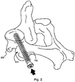
- Bone 200 may, for example, represent a human hip bone.
- bone screw 100 is disposed within bone 200 by rotating the bone screw 100 such that the bone screw threads 110 act to pull bone screw 100 into bone 200, thereby anchoring bone screw 100 into place.
- Bone screws may comprise any material suitable for placement into a bone without harmful effects on the patient.
- suitable materials include, but are not limited to, titanium and its alloys, tantalum and its alloys, nickel-cadmium and its alloys, steel and its alloys, plastics, absorbable materials, resorbable materials, polyamino acids, polylactide, polyglycolide, hydroxylapatite, and tricalciumphosphate.
- Other materials useful for bone screw construction will be known to those skilled in the art.
- the device further comprises a bone-screw insert.
- the term "insert" is used to refer to one or more cannulated members which are disposed within the cannulated portion of a bone screw.
- the insert 300 comprises a cannulated portion 310 which consists of a hollow cavity 320 surrounded by the insert wall 330, where the cavity and wall dimensions may be suitably chosen in order to carry out the practice of the device disclosed herewith.
- the insert may comprise a single piece, as disclosed in FIG. 3(a) .
- the insert may comprise two or more pieces or sections that, when taken together, form the insert. Referring now to FIG.
- the insert 300 when the insert 300 is a single piece, the insert comprises two ends, 302 and 304, connected by a shaft 306.
- the shaft may be cannulated along its entire length, creating openings at each end of the insert.
- the cannulation may extend only partially into the shaft so long as the cannulation is sufficient to allow for delivery of a substance from one end of the insert to one or more bone-screw fenestrations.
- One end 302 of the insert 300 may comprise threads 340 which interlock with bone screw threads 140 of Figure 1 to help fix an insert 300 into a bone screw 100.
- the insert comprises two or more pieces or sections, only one of the sections need be cannulated such that the insert sections, when taken together, allow for delivery of a substance from one end of the insert to one or more bone-screw fenestrations.
- the exterior dimensions of the insert are only slightly smaller than the interior dimensions of a cannulated bone screw to provide for a tight but sliding fit when the insert is placed into the bone screw, as depicted in FIG. 4 in which an insert 400 is shown partially disposed within a bone screw 410.
- an insert cap 415 which can be used to substantially seal the one end 402 of the insert 400 via insert cap threads 420 either before, during, or after the bone screw 410 and insert 400 are put into place.
- the insert may have substantially the same cross-sectional shape as the cannulated portion of the bone screw, or their cross-sectional shapes may be different.
- the internal bone screw cavity and the exterior surface of the insert may have a substantially circular cross-section.
- the insert may be rotated with respect to the screw to achieve alignment of certain of the insert and bone-screw fenestrations, for example.
- the insert and bone screw may have substantially non-circular cross-sections such that the insert is not free to rotate once it has been disposed within the bone screw.
- at least part of the insert cross-section may not match that of the bone screw cavity such that when the insert is disposed within the bone screw, one or more channels are formed longitudinally along at least part of the insert and bone screw shafts. Such channels may be useful, for example, to allow air or fluids to escape the bone screw cavity as the insert is introduced.
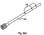
- the inserts may comprise one or more insert fenestrations 510, as depicted in FIG. 5(a) .
- An insert having an appropriate number, size, shape, and location of insert fenestrations can be chosen by the practitioner without undue experimentation to provide a delivery pathway between at least one end of the insert and the one or more bone-screw fenestrations.
- FIG. 5(b) discloses an insert 500 comprising a plurality of insert fenestrations 510 having a substantially rectangular cross-section.
- the delivery pathway may initiate at one end of the bone screw and pass through the insert to one or more bone-screw fenestrations.
- the insert fenestrations need not match the bone-screw fenestrations in number, size, shape, or location, although it may be advantageous to locate at least one of the insert fenestrations such that it may be substantially aligned with at least one bone-screw fenestrations once both the bone screw and the insert are in place.
- the inserts may be permeable to the substance to be delivered such that the substance is delivered to the exterior of the insert by diffusion through the insert wall or through small openings in the insert wall.
- Such openings may be intentionally created such as by increasing the porosity of the insert material (e.g., by introducing a series of pinpricks into the material), or they may exist naturally as pores in the material.
- an insert 600 comprising a cannulated portion 610 and a permeable material 620 wherein a substance to be delivered can travel from one end 602 of the insert to the permeable material 620.
- the insert may or may not be fenestrated so long as delivery of the desired substance is not completely impeded by the insert.
- An example comprising a permeable but non-fenestrated insert may be preferred when it is desired to effect a controlled, slow release of the desired substance to a bone, or when it is desired to prevent bone fragments, blood, fat or other materials or fluids from traveling from the exterior of the insert to the interior cavity.
- insert 700 with walls 710 surrounding a reservoir 720.
- One end 702 of the insert may be substantially sealed by insert cap 715.
- the insert may comprise a thin-walled tube which increases the available volume for storage of the substance, and which also increases the diffusion of the substance through the insert wall.
- the insert may comprise a film or coating on the interior surfaces of the bone-screw cavity. Inserts in accordance with this example may be as thin as a few hundred nanometers or less, which again may be beneficial for increasing the reservoir size with the bone screw and insert cavity, and for increasing the diffusion of the substance through the insert wall.
- the delivery of a substance to a bone may alternately be controlled or directed by diminishing the cavity size within the insert so that the movement of the substance is restricted.
- the insert cannulation or insert fenestrations be a few microns (e.g., 5 microns) or less in size.
- a cannulated portion 730 of insert 700 which is diminished in size so as to restrict or limit the flow of a substance from the reservoir 720.
- the exact configuration and geometry of an insert providing the desired level of substance delivery can be determined by one skilled in the art without undue experimentation.
- the inserts may control or direct the delivery of a substance to a bone through a fenestrated bone screw by substantially blocking one or more of the bone-screw fenestrations.
- This approach may be advantageous when it is desired to deliver the substance to a specific location with respect to the bone screw's position within the bone. Since the exact bone-screw fenestrations which align with or match this location may not be known until after the bone screw has been disposed within the bone, the bone screw inserts allow one to selectively block the bone-screw fenestrations to which substance delivery is not desired, while maintaining a substance delivery pathway to one or more bone-screw fenestrations to which substance delivery is desired. Moreover, by utilizing an insert whereby the insert fenestrations align with the bone-screw fenestrations to which substance delivery is desired, one may achieve substantially unimpeded delivery of the substance to the area of interest.
- the bone-screw inserts even when fenestrated, may be advantageously used to significantly hinder bone fragments, blood, fat, or other materials from entering the cannulated portion of the bone screw, especially during insertion of the bone screw into the bone, for example.
- the insert may then be subsequently re-positioned at a later time to align one or more of the insert fenestrations with the bone-screw fenestrations to facilitate substance delivery.
- Inserts may comprise any material compatible with the bone screw and able to be placed within the bone screw without producing adverse effects to the patient.
- suitable insert materials include, but are not limited to, titanium and its alloys, tantalum and its alloys, nickel-cadmium and its alloys, steel and its alloys, plastics, absorbable materials, resorbable materials, polyamino acids, polylactide, polyglycolide, hydroxylapatite, and tricalciumphosphate.
- Other materials useful for insert construction will be known to those skilled in the art.
- the insert comprises two or more sections, the sections need not comprise the same material.
- one or more of the insert sections may comprise a material specifically chosen to impart the desired level of permeability to the insert.
- the insert may be sold or otherwise provided in a kit containing two or more inserts having different fenestrations or permeability characteristics.
- a kit containing two or more inserts having different fenestrations or permeability characteristics.
- the availability of such a kit has the advantage of allowing a practitioner to select an appropriate insert based on the particular needs of the patient.
- the insert is disposed within the bone screw to provide for a directed or controlled delivery of a desired substance to a bone.
- the term "substance” is used to refer to one or more chemical compounds that are useful when delivered to the vicinity of a bone. Substances may be chosen to help treat diseased bone as well as fractured or otherwise injured bones. Alternatively, the substance may be delivered to otherwise healthy bone to help maintain overall bone health, for example. Representative example substances include medicants or therapeutics such as antibiotics, chemotherapeutics, angiogenic factors, bone morphogenic proteins, and bone growth factors. Other desirable substances may be known or hereinafter determined by one skilled in the art.
- the device may further comprise a reservoir.
- the term "reservoir” refers to any source of the one or more substances to be delivered to the vicinity of a bone.
- the reservoir may comprise the hollow cavity created by the cannulation of the bone-screw insert and any part of the bone-screw cannulation not occupied by the insert, as depicted in FIG. 7 and described above.
- the substance to be delivered may be absorbed into a sponge-like material such as a collagen, for example, which may then be disposed within the cannulated portion of the bone screw or insert, or both.
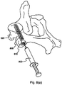
- FIG. 8(a) discloses a bone screw 800 and an insert 810 disposed therein, both of which are disposed within a bone 820.
- FIG. 8(a) further discloses a syringe 830 which acts as a reservoir to provide a substance to the bone 820 via bone screw 800 and insert 810.
- FIG. 8(b) discloses an IV 840 which serves as a reservoir for delivering a substance to a bone via a bone screw and an insert.
- the reservoir may be implanted beneath the patient's skin, i.e., subcutaneously.
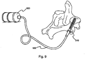
- the device may further include a pump 920, as depicted in FIG. 9 , for delivering a substance to a bone via a bone screw and an insert 910, and tubing 930.
- a pump may be utilized to aid in delivery of the substance to the vicinity of a bone by, for example, delivering a continuous, regulated volume to the screw.
- the pump may also be used to increase the fluid pressure within the cannulated portion of the insert, thereby aiding fluid flow through the insert fenestrations or insert walls, for example.
- This example may have the further advantage that the positive pressure created by the pump within the cannulated portion of the insert or bone screw hampers the influx of unwanted materials or compounds into the device.
- the pump may be connected to the cannulated portion of the bone screw or insert as depicted in FIG. 9 , and the pump may also be implanted subcutaneously if desired.
- Examples of pumps which may be suitably used in the practice of the current invention are the implantable pumps disclosed in U.S. Patent No. 4,588,394 , for example.
- Other examples may be relatively simple pumps such as external pumps similar to those used with patient controlled anesthesia machines or simple IV pumps.
- the bone screw may be a fixation nail that holds two or more bones or bone parts in a fixed spatial relationship.
- the exterior of the bone screw shaft is unthreaded.
- the fixation nail may be adapted for use in the fixation of a variety of bones, including, but not limited to, femur fixations, humerus fixations and tibia fixations.
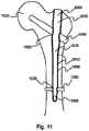
- a femur fixation nail 1000 disposed within a femur 1002.
- the fixation nail has two ends 1004 and 1006 connected by a shaft 1008.
- the fixation nail includes a cannulated portion 1010, which is best seen in the cross-sectional view of FIG. 11 , and fixation nail fenestrations 1012 along the length of the cannulated portion 1010.
- One end of the cannulated portion 1010 of the fixation nail 1000 may be configured to accept a nail insert 1020. This is demonstrated in FIG.
- the fixation nail may define one or more bores 1030 through its length through which fixation screws 1040 and 1050 may be passed in order to affix the fixation nail to the bone.
- the fixation screws may pass through the fixation nail substantially perpendicular to the long axis of the nail or they may pass through the nail at acute or obtuse angles with respect to the long axis of the nail.
- fixation screw that passes through the cannulated portion of a fixation nail are desirably selected such that the screw does not substantially impede the passage of a substance to be delivered to the bone.
- fixation screw may itself include a bore through its length that allows for the passage of the substance.
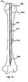
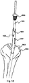
- a humerus fixation nail 1300 disposed within a humerus 1302.
- the fixation nail has two ends 1304 and 1306 connected by a shaft 1308.
- the fixation nail includes a cannulated portion 1310, which is best seen in the cross-sectional view of FIG. 14 , and fixation nail fenestrations 1312 along the length of the cannulated portion 1310.
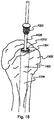
- One end of the cannulated portion 1310 of the fixation nail 1300 may be configured to accept a nail insert 1320. This is demonstrated in FIG. 15 which shows a perspective view of a nail insert 1320 being inserted into the cannulated portion 1310 of the fixation nail 1300.
- the fixation nail 1300 has internal threads (not shown) on one end of its cannulated portion 1310 to promote fixation of the nail insert 1320 which also has threads 1325 on one end.
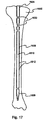
- a tibia fixation nail 1600 disposed within a tibia 1602.
- the fixation nail has two ends 1604 and 1606 connected by a shaft 1608.
- the fixation nail includes a cannulated portion 1610, which is best seen in the cross-sectional view of FIG. 17 , and fixation nail fenestrations 1612 along the length of the cannulated portion 1610.
- One end of the cannulated portion 1610 of the fixation nail 1600 may be configured to accept a nail insert. This is demonstrated in FIG. 18 which shows a perspective view of the a nail insert 1620 being inserted into the cannulated portion 1610 of the fixation nail 1600.
- the fixation nail 1600 has internal threads (not shown) on one end of its cannulated portion 1610 to promote fixation of the nail insert 1620 which also has threads 1625 on one end.
- the fixation nail need not be straight along its entire length, but may include one or more angles to facilitate the placement of the nail into a bone.
- the fixation nail may define one or more bores 1630 through its length through which fixation screws 1640, 1642, 1644 and 1646 may be passed in order to affix the fixation nail to the bone.
- the fixation screws may pass through the fixation nail substantially perpendicular to the long axis of the nail or they may pass through the nail at acute or obtuse angles with respect to the long axis of the nail.
- the bores may be aligned substantially parallel with respect to one another, substantially perpendicular with respect to one another or may be aligned at angles between parallel and perpendicular.
- FIG. 19 discloses one illustrative example in which an IV 1900 serves as a reservoir for delivering a substance to a tibia via the fixation nail of FIG. 18 .
- FIG. 20 discloses an alternative example where a pump 2000 serves as the reservoir for delivering a substance to a tibia via the fixation nail of FIG. 18 .
- the delivery pathway between one or more insert fenestrations and one or more bone screw fenestrations is defined by two balloons, each of which is inflated between the outside of the insert and the inside of the bone screw to form a seal between the insert and the bone screw.
- FIGS. 21 and 22 This is exemplified in FIGS. 21 and 22.
- FIG. 21 shows a bone screw insert 2100 having a fenestration 2110 along its length.
- a first balloon 2120 is disposed around the outside of the insert 2100 above the fenestration 2110 and a second balloon 2130 is disposed around the outside of the insert 2100 below the fenestration 2110.
- the insert optionally has threads 2140 at one end that interlock with bone screw threads 2150 in a bone screw 2160 to help fix the insert 2100 into the bone screw 2160.
- the first and second balloons may be inserted into a bone screw in a deflated state. As shown in FIG. 22 , when the insert is in place inside the bone screw the balloons 2120 and 2130 are disposed above and below one or more fenestrations 2170 in the bone screw. Once the insert is in place, the balloons may be inflated to form a seal between the outside 2180 of the insert 2100 and the inside 2190 of the bone screw 2160, isolating the insert fenestration 2110 and the bone screw fenestrations 2170 between the balloons. In this manner, the balloons help to define a delivery pathway between one or more insert fenestrations and one or more bone screw fenestrations.
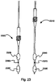
- FIG. 23 shows two different bone-screw inserts 2300 and 2310, each having a pair of balloons 2320, 2330 and 2340, 2350 disposed along its length and situated above and below an insert fenestration 2360 and 2370.
- the bone-screw inserts have different lengths, such that they may be adapted for insertion into bone screws of different lengths or may be used to isolate fenestrations at different locations along the shaft of a given bone screw.
- the insert and bone screw fenestrations of FIGS. 21-23 are isolated between two inflated balloons, it should be understood that other configurations are possible.
- one or more insert fenestrations and one or more bone screw fenestrations could be isolated between a single inflated balloon and the top end or the bottom end of the bone screw.
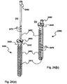
- FIGS. 24a and b An alternative design for a substance delivery device is shown in FIGS. 24a and b.
- a bone screw 2400 is provided with an attachment mechanism, shown as an exterior groove 2410, running along its length.
- the bone screw includes a head 2420 that defines a longitudinal bore 2430 having internal threads 2440.
- a cannulated insert 2450 adapted to fit through the longitudinal bore 2430 and into the groove 2410 is also provided.
- the insert includes a head 2460 adapted to accept a tube (not shown), or similar means for delivering a substance, and a plurality of fenestrations 2470 along its length. As shown in FIG.
- FIG. 24 shows a perspective view of the delivery device of FIG. 24 connected to a substance delivery tube 2500 and inserted into the hip bone 2510 of a patient.
- FIG. 26 depicts a substance delivery device, similar to that of FIG. 25 , where an exterior insert is combined with a fixation nail.
- FIG. 26a shows a cannulated insert 2600 having a head 2610 adapted to receive a tube (not shown), or similar substance delivery means, at one end and a plurality of fenestrations 2620 along its length.
- the insert is adapted to fit into a groove 2630 running along the external surface of a fixation nail 2640.
- the fixation nail need not be straight along its entire length, but may include one or more angles to facilitate the placement of the nail into a bone.
- the fixation nail may define one or more bores 2650 through its length through which bone screws (not shown) may be inserted to fix the nail to the bone.
- the fixation nail may itself include one or more fenestrations 2660 along its length.
- FIG. 27 shows a perspective view of the delivery device of FIG. 26b inserted into the tibia 2700 of a patient.
- the method may comprise introducing a cannulated, fenestrated bone screw into a bone, introducing a cannulated insert into the bone screw, and introducing a substance to be delivered into the cannulated portion of the insert.
- the method may comprise attaching a cannulated insert along at least a portion of an exterior surface of a bone screw, introducing the bone screw into a bone, and introducing a substance to be delivered into the cannulated portion of the insert. Under some circumstances, one may find it advantageous to introduce the insert into or along the bone screw, in its entirety or only partially, prior to introducing the bone screw into the bone.
- This sequence might be preferred in order to shorten the overall surgery time, or to reduce the amount of material that enters the bone-screw fenestrations from outside the screw during screw insertion, for example. Alternately, other circumstances may make it more advantageous to introduce the insert into the bone screw, in its entirety or only partially, after the bone screw is introduced into the bone. This latter sequence might be preferred in order to be able to determine which screw fenestrations or exterior insert attachment mechanisms (e.g. grooves) are located at the optimum location for delivery of the desired substance, and thus what insert configuration or length should be used to facilitate substance delivery to desired locations in or near a bone.
- screw fenestrations or exterior insert attachment mechanisms e.g. grooves
- sequences can be envisioned by one skilled in the art, such as for example, partially introducing the bone screw into a bone, partially or completely inserting the insert into or along the bone screw, and then completing the insertion of the bone screw into the bone. Even more sequence variations are possible when one considers the additional step of introducing the substance into the cannulated portion of the bone screw insert, and all such sequence variations are to be included within the scope of this disclosure.
- the method may further comprise the steps of holding or fixing two or more bones or bone pieces in a fixed spatial relationship with respect to each other.
- a method may be desirable when it is desired to deliver a substance such as a medicant or therapeutic to the vicinity of a site where a peripheral skeletal fracture or an osteotomy is mended, a spondyloysis or an odontoid fracture repaired, or lumbar facet joints are fused.
- Another example may further comprise the method of delivering a substance to the vicinity of a bone including the steps of attaching a reservoir, a pump, or both, to the bone screws or bone-screw inserts disclosed herein.
- Such reservoirs and pumps may aid in the continuous, regulated, or long-term delivery of the desired substance to the vicinity of a bone, thereby facilitating the healing process or the overall health of the bone and its surrounding tissues.
- the bone screw and insert examples disclosed herein may be configured to allow for re-sealing and multiple time or multiple use access to the cannulated portion of the bone screw or insert.
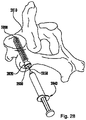
- a bone screw 2800 is shown inserted or disposed within a bone 2810.
- An insert 2820 is shown inserted within bone screw 2800.
- a seal shown as an insert cap 2830, is coupled to the outer or proximal end of insert 2820.
- insert cap 2830 is an end cap directly coupled to the inner surface of insert 2820.
- Insert cap 2830 acts to seal the outer or proximal end of insert 2820.
- the seal may be positioned along the shaft of the insert.
- cap 2830 is removably coupled to insert 2820, and in other examples, cap 2830 may be coupled to insert 2820 via a non-removable (i.e., permanent) coupling.
- a fluid delivery device shown as syringe 2840, includes a needle 2850.
- Insert 2820 includes a shaft 2822, an opening 2824 located at the proximal end of insert 2820, and at least one insert fenestration 2826 located through shaft 2822.
- the shaft 2822 of insert 2820 also includes a cannulation 2828 formed along at least a portion of shaft 2822.
- opening 2824 is located at one end of cannulation 2828.
- the opening 2824 of insert 2820 is closed or sealed by cap 2830.
- cap 2830 includes an inner surface facing or in communication with cannulation 2828.
- Cap 2830 may be coupled to or attached to insert 2820 by any suitable means.
- cap 2830 may be threaded to mate with threads located within opening 2824, and, in other examples, cap 2830 may be press fit into opening 2824 or may be attached to opening 2824 with an adhesive.
- opening 2824 may be located along the sidewall of the insert, and cap 2830 may seal the opening along the sidewall of the insert.
- Insert cap 2830 may be able to provide multiple-time or reusable access to cannulation 2828 of the insert following implantation of the bone screw/insert combination into the bone.
- reusable, post-implantation access to cannulation 2828 of insert 2820 is provided by self-sealing cap 2830.
- cap 2830 comprises a resilient, self-sealing material, and needle 2850 pierces through cap 2830 providing access to cannulation 2828.
- needle 2850 creates a perforation 2834 that extends through cap 2830.
- a substance 2832 may be delivered from the fluid delivery device into cannulation 2828.
- the substance may be delivered through insert fenestrations 2826 and through bone screw fenestrations as discussed in the various examples above.
- needle 2850 may be removed or withdrawn from cap 2830. Once needle 2850 is withdrawn, perforation 2834 self-seals to prevent substance 2832 from flowing out of the proximal end of insert 2820 through perforation 2834. The process of inserting needle 2850 through cap 2830 may be repeated as necessary to deliver multiple doses of a substance to insert 2820. While the fluid delivery device is shown in FIG. 28 as syringe 2840, in various other examples, needle 2850 may be connected to a variety of fluid delivery devices.
- the fluid delivery device may be a pump (e.g., an infusion pump) or a bag or reservoir or fluid bag (similar to an IV bag) coupled to needle 2850 via tubing.
- the fluid delivery device may be a micro-infusion device in fluid communication with the cannulated portion of the insert and/or bone screw.
- the micro-infusion pump may be worn by a user, and a substance may be continuously delivered through the bone screw and/or insert to promote bone growth.
- Cap 2830 may be made from any material or combination of materials that provides for resealing or self-sealing.
- cap 2830 may be made from a compliant, non-rigid or resilient material that resiliently expands following withdrawal of needle 2850 to seal perforation 2834 caused by needle 2850.
- cap 2830 may be made from a surgical, self-sealing rubber or polymer, such as surgical silicone rubber.
- the post-implantation access to cannulation 2828 of insert 2820 provided by cap 2830 may allow the user to deliver a new or second substance or additional doses of a same substance to the bone as needed to treat a particular patient.
- a new or second substance or additional doses of a same substance may be delivered to a fracture site via insert 2820.
- insert 2820 may be used for repeated delivery of cancer treating drugs (e.g., anti-cancer drugs) to the bone in which the bone screw is implanted.
- cancer treating drugs e.g., anti-cancer drugs
- bone morphogenic proteins may be delivered in separate doses to the bone via insert 2820.
- any other substance that may be intermittently delivered to a patient may be delivered using insert 2820.
- insert 2820 and resealing cap 2830 allow the user to change either the dose or the type of substance delivered to a patient each time needle 2850 is inserted through cap 2830.
- post-implantation access to cannulation 2828 of insert 2820 by needle 2850 may allow for the post-implantation connection of any desired fluid delivery device (e.g., an IV or infusion pump) to the insert by connecting the fluid delivery device to needle 2850. This may allow the user to switch or change the type of fluid delivery device used to deliver fluid to the bone via the bone screw/insert combination.
- any desired fluid delivery device e.g., an IV or infusion pump
- needle 2850 may also be connected to a material removal device allowing for repeat and resealing access through cap 2830 for removal of material from cannulation 2828 of insert 2820, as described below in relation to FIGS. 30(a) and 30(b) .
- the user will need to align needle 2850 with cap 2830 following implantation of the implanted bone screw/insert combination.
- the bone screw/insert combination may be located a small distance below the skin such that cap 2830 may be palpated through the skin allowing the user to align the needle with cap 2830 by touch.
- the bone screw/insert combination may be located in a bone deeper below the skin such that alignment via palpation may be difficult or impossible.
- needle 2850 may be aligned with cap 2830 by imaging the location of the cap 2830 via a suitable imaging device (e.g., via X-ray, CT, etc.).
- bone screw 2800 may include a resealing cap, shown as bone screw cap 2860 (similar to cap 2830), that is coupled to or attached to bone screw 2800 such that bone screw cap 2860 seals the proximal opening 2862 of bone screw 2800.
- bone screw 2800 includes a bone screw cannulation 2864 and bone screw fenestrations 2866. With needle 2850 extending through cap 2860, material may be delivered to a bone through bone screw fenestrations 2866, and, as discussed below, material may be removed from the bone through bone screw fenestrations 2866. As shown in FIG. 29(c) , bone screw cap 2860 may seal bone screw 2800 without an insert disposed within a bone screw cannulation 2864. In another example, bone screw cap 2860 may seal the proximal opening 2862 of bone screw 2800 with an insert disposed within bone screw cannulation 2864. Further, it should be understood that various examples of resealing caps 2830, 2860 may be used with any of the bone screw and insert examples discussed herein.
- a material removal system 2900 includes a bone screw 2910, a bone screw insert 2930 and a material removal device, shown as suction device 2950 (e.g., a pump, vacuum, etc.).
- Bone screw 2910 includes a sidewall 2912, a threaded portion, shown as threads 2914, formed on the inner surface of sidewall 2912, and a bone screw cannulated portion 2916.
- Bone screw 2910 also includes at least first fenestrations 2918 and second fenestrations 2920. In the orientation of FIG. 30(a) , fenestrations 2918 are located above (i.e., closer to the proximal end of bone screw 2910) fenestrations 2920.
- Insert 2930 includes a first expandable portion, shown as first balloon 2932, and a second expandable portion, shown as second balloon 2934.
- Insert 2930 includes an insert fenestration 2936 located between balloons 2932 and 2934.
- balloons 2932 and 2934 may be inflated to form seals with the inner surface of bone screw 2910 to provide for isolation of one or more of the bone screw fenestrations.
- Insert 2930 includes a threaded portion, shown as threads 2938, that engages with threads 2914 of bone screw 2910. While material removal system 2900 is shown and described with an insert that includes expandable sections, it should be understood that material removal system 2900 may utilize any of the bone screw/insert combinations discussed herein.
- Material removal system 2900 includes a material removal device, shown as suction device 2950, connected to insert 2930 via a tubing 2952.
- Suction device 2950 is configured to extract or aspirate material from cannulated portion 2916 of the bone screw and from the area surrounding the bone screw.
- suction device 2950 may be a motorized suction device or maybe a manual suction device (e.g., a syringe).
- balloons 2932 and 2934 are inflated to isolate fenestrations 2918.
- suction device 2950 applies a vacuum to insert 2930 via tubing 2952 such that material is drawn in through fenestrations 2918 and is moved through the insert and tubing to reach the suction device.
- suction device 2950 allows for removal or harvesting of material adjacent fenestrations 2918.
- material removal system 2900 may be removed for various purposes, including for diagnostic testing and/or for subsequent implantation.
- material may be removed for various purposes, including for diagnostic testing and/or for subsequent implantation.
- bone marrow may be harvested using material removal system 2900 to be used for bone marrow donation or for diagnostic testing.
- Other materials, such as blood, may be removed for diagnostic testing.
- various materials may be removed from the bone screw using suction device 2950 to test for the presence of infection within the bone at the site of implantation of the bone screw.
- material removal system 2900 may be used to harvest osteoprogenitor cells from the bone of the patient into which bone screw 2910 is inserted.
- the harvested osteoprogenitor cells harvested using material removal system 2900 may then be implanted into another area of the patient (e.g., another bone) where bone growth is desired.
- material removal system 2900 may be used to remove osteoprogenitor cells from one location in a patient, and then the removed osteoprogenitor cells may be implanted using one of the bone screw/insert combinations discussed herein located at another position within the patient.
- the osteoprogenitor cells may be combined with other materials (e.g., calcium phosphate, hydroxylapatite, demineralized bone matrix, etc.) that may facilitate or enhance bone growth that results from the osteoprogenitor cells.
- bone screw 2910 includes a plurality of fenestrations (e.g., fenestrations 2918 and 2920).
- insert 2930 and the plurality of fenestrations of bone screw 2910 allow the user to select or to isolate individual fenestrations or groups of fenestrations to selectably harvest material through the selected fenestrations.
- insert 2930 is shown harvesting material through fenestrations 2918.
- FIG. 30(a) insert 2930 is shown harvesting material through fenestrations 2918.
- insert 2930 is shown positioned within bone screw 2910 such that fenestrations 2920 are isolated between balloons 2932 and 2934. In this position, operation of suction device 2950 allows for removal of material through fenestrations 2920, as depicted by arrows 2956. This arrangement allows the user to selectively take samples of removed material from various positions within the bone.
- insert 2930 may include a resealing cap, such as cap 2830, that allows suction device 2950 to be connected to the cannulated portion of the insert via a needle, such as needle 2850.
- the material removal device may be a device other than a suction-based aspiration device.
- the material removal device may be any other suitable material removal device such as an absorbent device (e.g., a swab) that absorbs material located within either the cannulated portion of the bone screw or the insert.
- a bone screw may include one or more fenestrations shaped as a slot extending longitudinally along the shaft of a bone screw.
- bone screw 3000 is shown .
- Bone screw 3000 includes a shaft 3010 and bone screw threads 3020.
- Bone screw 3000 includes a cannulation 3030, a first fenestration 3040, a second fenestration 3050, and a third fenestration 3060.
- First fenestration 3040 and second fenestration 3050 are configured as rectangular slots that extend in the longitudinal direction along shaft 3010.
- first fenestration 3040 in the longitudinal direction is approximately a quarter of the longitudinal length of shaft 3010 and the length of second fenestration 3050 in the longitudinal direction is approximately half of the longitudinal length of shaft 3010.
- Third fenestration 3060 is shown as a smaller slot-shaped fenestration located near the distal end of bone screw 3000.
- fenestrations such as fenestrations 3040, 3050 and 3060, may be of other lengths relative to shaft 3010 (e.g., 1/8 of the length of shaft 3010, 1/4 of the length of shaft 3010, 1/2 of the length of shaft 3010, and 3/4 of the length of shaft 3010, etc.).
- threads 3020 are shown including gaps or spaces at the location of fenestrations 3040, 3050 and 3060.
- threads 3020 may be contiguous threads that extend above or overlap fenestrations 3040, 3050 and 3060.
- Fixation nail 3100 disposed within a femur 1002 is shown.
- Fixation nail 3100 includes a shaft 3110 which is cannulated.
- Fixation nail 3100 is similar to fixation nail 1000 shown in FIG. 10 except that fixation nail 3100 includes three rectangular-shaped slot fenestrations 3120, 3130 and 3140 that extend in the longitudinal direction along shaft 3110. In the example shown, all of the fenestrations 3120, 3130 and 3140 are generally of the same size and shape.
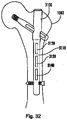
- FIGS. 31 and 32 show two bone screw examples including slot-shaped fenestrations
- any of the bone screws discussed herein may include one or more slot-shaped fenestrations.
- the bone screw embodiments of FIGS. 31 and 32 show bone screws having three slot-shaped fenestrations
- the bone screws may include any number of slot-shaped fenestrations (e.g., 1, 2, 4, 5, 6, 7, 8, etc.) as needed for a particular application, procedure, patient, etc.
- the slot-shaped fenestrations are shown as rectangular in shape, other shapes may be used (e.g., oval, elliptical, diamond, triangular, etc.).
- slot-shaped fenestrations may assume other positions or orientations relative to the shaft of the bone screw.
- a slot-shaped fenestration may be a circumferentially oriented fenestration such that the longer axis of the fenestration is perpendicular to the longitudinal axis of the shaft (as shown in FIG. 10 ).
- Bone screw 3210 is shown implanted or disposed within a bone 3200.
- Bone screw 3210 includes a sidewall 3212, a threaded portion, shown as threads 3214, formed on the inner surface of sidewall 3212, and a bone screw cannulated portion 3216.
- bone screw 3210 includes first fenestrations 3218 and second fenestrations 3220.
- Fenestrations 3218 and 3220 are slot-shaped fenestrations that extend longitudinally along sidewall 3212.
- Bone screw 3210 may be a threaded bone screw, such as bone screw 3000, a fixation nail, such as femur fixation nail 3100, or any other bone screw embodiment disclosed herein.
- fenestrations 3218 are located above (i.e., closer to the proximal end of bone screw 3210) fenestrations 3220.
- Insert 3230 is shown positioned within cannulated portion 3216 of bone screw 3210.
- Insert 3230 includes a first expandable portion, shown as first balloon 3232, and a second expandable portion, shown as second balloon 3234.
- Insert 3230 includes an insert fenestration 3236 located between balloons 3232 and 3234.
- the longitudinal length, L1, of fenestrations 3218 and/or the longitudinal length, L2, of fenestrations 3220 are greater than the longitudinal length, L3, of the portion of insert 3230 that is located between first balloon 3232 and second balloon 3234.
- insert 3230 may be positioned such that insert fenestration 3236 is located adjacent the upper ends of fenestrations 3218. With insert 3230 in this position, balloons 3232 and 3234 may be inflated to provide for isolation or selection of the upper portions of fenestrations 3218.
- a substance may be delivered through insert fenestration 3236 to the portion of bone 3200 adjacent the isolated section of fenestrations 3218, and/or a material may be removed from the portion of bone 3200 adjacent the isolated section of fenestrations 3218 via insert 3230, as discussed in the various embodiments above.
- upper balloon 3232 is expanded to form an upper seal between the outer surface of the balloon and the inner surface of the bone screw and/or the tissue adjacent the bone screw fenestration
- lower balloon 3234 is expanded to form a lower seal between the outer surface of the balloon and the inner surface of the bone screw and/or the tissue adjacent the bone screw fenestration.
- the lower surface of upper balloon 3232 and the upper surface of lower balloon 3234 define a sealed chamber or section 3242 that isolates a portion of the adjacent bone screw fenestration.
- Insert fenestration 3236 is located within sealed section 3242, and thus, a pathway is defined between the portion of bone 3200 adjacent the sealed section 3242 and the proximal end of insert 3230.
- a substance may be delivered to bone 3200 via the pathway and/or a material may be removed from bone 3200 via the pathway as discussed above in the various embodiments.
- FIGS. 33(a), 33(b), and 33(c) show the isolation of various portions of fenestrations 3218 according to various exemplary embodiments.
- upper balloon 3232 is expanded to form an upper seal with the inner surface of bone screw 3210 above fenestrations 3218
- lower balloon 3234 is expanded to form a lower seal with both the tissue (e.g., bone 3200) adjacent to fenestrations 3218 and with the inner surface of bone screw 3210 that is laterally adjacent to fenestrations 3218 (not visible in the section view of FIG. 33(a) ).
- tissue e.g., bone 3200
- both upper balloon 3232 and lower balloon 3234 are expanded to form seals with the tissue (e.g., bone 3200) adjacent to fenestrations 3218 and with the inner surface of bone screw 3210 that is laterally adjacent to fenestrations 3218 (not visible in the section view of FIG. 33(b) ).
- tissue e.g., bone 3200
- lower balloon 3234 is expanded to form a lower seal with the inner surface of bone screw 3210 below fenestrations 3218
- upper balloon 3232 is expanded to farm an upper seal with both the tissue (e.g., bone 3200) adjacent to fenestrations 3218 and with the inner surface of bone screw 3210 that is laterally adjacent to fenestrations 3218 (not visible in the section view of FIG. 33(c) ).
- an upper portion of balloon 3234 is shown expanding to seal against the lower surface 3238 of fenestrations 3218 by expanding through laterally through fenestration 3218.
- both balloons 3232 and 3234 may be configured to allow for expansion through the fenestrations to provide for sealing as shown in FIG. 33(c) .
- FIGS. 33(a), 33(b), and 33(c) show three exemplary positions at which insert 3230 may be used to isolate portions of fenestrations 3218, it should be understood that insert 3230 maybe moved to any position relative to the fenestration as desired by the user. In the embodiment shown, the positioning may be selected by advancing insert 3230 through threads 3214 of bone screw 3210 via cooperation of insert threads 3240. While FIGS. 33(a), 33(b) and 33(c) depict selection of various portions of fenestrations 3218, it should be understood that insert 3230 may be sized and configured such that portions of any fenestration of bone screw 3210 may be selected as discussed above.
- a method for removing a substance from a bone comprising: introducing a bone screw into the bone, the bone screw having two ends connected by a shaft and a portion adapted to be attached to an insert; attaching the insert to the bone screw, the insert having two ends connected by a shaft, wherein the shaft of the insert is cannulated along at least a portion of its length, the insert further comprising an insert fenestration disposed along the cannulated portion of the insert; coupling a device to the insert and in communication with the cannulated portion of the insert; and removing material from the bone through the insert fenestration via the device.
- the device comprises a pump.
- the shaft of the bone screw is cannulated along at least a portion of its length
- the step of attaching the insert to the bone screw comprises introducing the insert into the cannulated portion of the bone screw shaft, wherein the bone screw comprises a first bone screw fenestration and a second bone screw fenestration disposed along the cannulated portion of the bone screw
- the removing step comprises: placing the insert into a first position wherein material is removed from the bone through the first bone screw fenestration; and placing the insert into a second position wherein material is removed from the bone through the second bone screw fenestration.
- the insert further comprises an expandable portion positioned along the shaft of the insert, the method further comprising: expanding the expandable portion when the insert is in the first position; and expanding the expandable portion when the insert is in the second position.
- the material removed from the bone comprises osteoprogenitor cells, and wherein the method further comprises implanting the removed osteoprogenitor cells into a another bone to promote bone growth.
Landscapes
- Health & Medical Sciences (AREA)
- Orthopedic Medicine & Surgery (AREA)
- Life Sciences & Earth Sciences (AREA)
- Surgery (AREA)
- Engineering & Computer Science (AREA)
- Animal Behavior & Ethology (AREA)
- Public Health (AREA)
- Heart & Thoracic Surgery (AREA)
- Medical Informatics (AREA)
- Biomedical Technology (AREA)
- Veterinary Medicine (AREA)
- General Health & Medical Sciences (AREA)
- Molecular Biology (AREA)
- Nuclear Medicine, Radiotherapy & Molecular Imaging (AREA)
- Neurology (AREA)
- Pathology (AREA)
- Dermatology (AREA)
- Anesthesiology (AREA)
- Hematology (AREA)
- Surgical Instruments (AREA)
- Prostheses (AREA)
Claims (4)
- System (2900) zum Entfernen einer Substanz aus einem Knochen, Folgendes umfassend:einen Einsatz (3230), der zwei durch eine Welle verbundene Enden aufweist, wobei die Welle des Einsatzes (3230) entlang wenigstens eines Abschnitts seiner Länge kanüliert ist;eine Einsatzfensterung (3236), die entlang des kanülierten Abschnitts des Einsatzes (3230) angeordnet ist;eine Knochenschraube (3210), die zwei durch eine Welle verbundene Enden aufweist, wobei die Knochenschraube (3210) zum Aufnehmen des Einsatzes (3230) angepasst ist und mehrere Fensterungen (3218, 3220) einschließt;eine Vorrichtung (2950), die mit dem Einsatz (3230) gekoppelt ist und mit dem kanülierten Abschnitt des Einsatzes (3230) in Verbindung steht, wobei die Vorrichtung (2950) konfiguriert ist, um ein Material aus dem Knochen durch die Einsatzfensterung in den Einsatz hineinzuziehen; undeinen ersten expandierbaren Abschnitt (3232) und einen zweiten expandierbaren Abschnitt (3234), die jeweils um einen Abschnitt der Länge des Einsatzes (3230) herum angeordnet sind, wobei sich die Einsatzfensterung (3236) zwischen dem ersten und dem zweiten expandierbaren Abschnitt (3232, 3234) befindet, und wobei der erste und der zweite expandierbare Abschnitt (3232, 3234) konfiguriert sind, um sich zu expandieren, um eine Dichtung zwischen dem Einsatz (3230) und der Knochenschraube (3210) oder einem Gewebe angrenzend an die Fensterung (3218, 3220) der Knochenschraube (3210) auszubilden, dadurch gekennzeichnet, dass die Längslänge (L1, L2) von wenigstens einer Fensterung in der Knochenschraube (3210), die größer als die Längslänge (L3) des Abschnitts des Einsatzes (3230) ist, der sich zwischen dem ersten expandierbaren Abschnitt (3232) und dem zweiten expandierbaren Abschnitt (3234) befindet.
- System (2900) nach Anspruch 1, wobei die Welle der Knochenschraube (3210) entlang wenigstens eines Abschnitts ihrer Länge kanüliert ist, und ferner, wobei die Knochenschraube (3210) angepasst ist, um den Einsatz (3230) in der Kanülierung der Knochenschraube (3216) aufzunehmen.
- System (2900) nach Anspruch 1, wobei das Äußere der Welle der Knochenschraube (3210) einen Befestigungsmechanismus einschließt, und ferner, wobei die Knochenschraube (3210) angepasst ist, um den Einsatz in den Befestigungsmechanismus aufzunehmen.
- System (2900) nach Anspruch 1, wobei die Vorrichtung (2950) eine Pumpe umfasst.
Applications Claiming Priority (2)
| Application Number | Priority Date | Filing Date | Title |
|---|---|---|---|
| US12/822,022 US8062270B2 (en) | 2003-07-15 | 2010-06-23 | Method and device for delivering medicine to bone |
| US13/886,945 US9949777B2 (en) | 2003-07-15 | 2013-05-03 | Method and device for delivering medicine to bone |
Publications (2)
| Publication Number | Publication Date |
|---|---|
| EP2399533A1 EP2399533A1 (de) | 2011-12-28 |
| EP2399533B1 true EP2399533B1 (de) | 2020-11-18 |
Family
ID=66482069
Family Applications (2)
| Application Number | Title | Priority Date | Filing Date |
|---|---|---|---|
| EP11250603.5A Active EP2399533B1 (de) | 2010-06-23 | 2011-06-22 | System zum Entfernen einer Substanz aus einem Knochen |
| EP14734270.3A Active EP2991571B1 (de) | 2010-06-23 | 2014-04-25 | Vorrichtung zur abgabe einer medizin an einen knochen |
Family Applications After (1)
| Application Number | Title | Priority Date | Filing Date |
|---|---|---|---|
| EP14734270.3A Active EP2991571B1 (de) | 2010-06-23 | 2014-04-25 | Vorrichtung zur abgabe einer medizin an einen knochen |
Country Status (4)
| Country | Link |
|---|---|
| US (5) | US8062270B2 (de) |
| EP (2) | EP2399533B1 (de) |
| CN (1) | CN105377165A (de) |
| WO (1) | WO2014179177A1 (de) |
Families Citing this family (106)
| Publication number | Priority date | Publication date | Assignee | Title |
|---|---|---|---|---|
| US7648509B2 (en) * | 2003-03-10 | 2010-01-19 | Ilion Medical Llc | Sacroiliac joint immobilization |
| US7527611B2 (en) * | 2003-07-15 | 2009-05-05 | Spinal Generations, Llc | Method and device for delivering medicine to bone |
| US8870836B2 (en) | 2003-07-15 | 2014-10-28 | Spinal Generations, Llc | Method and device for delivering medicine to bone |
| US8062270B2 (en) | 2003-07-15 | 2011-11-22 | Spinal Generations, Llc | Method and device for delivering medicine to bone |
| US20180228621A1 (en) | 2004-08-09 | 2018-08-16 | Mark A. Reiley | Apparatus, systems, and methods for the fixation or fusion of bone |
| US8821506B2 (en) * | 2006-05-11 | 2014-09-02 | Michael David Mitchell | Bone screw |
| US7931651B2 (en) * | 2006-11-17 | 2011-04-26 | Wake Lake University Health Sciences | External fixation assembly and method of use |
| US10758283B2 (en) * | 2016-08-11 | 2020-09-01 | Mighty Oak Medical, Inc. | Fixation devices having fenestrations and methods for using the same |
| US20230380979A1 (en) * | 2007-10-30 | 2023-11-30 | Mjp Innovations, Inc. | Femoral neck support structure, system, and method of use |
| US8740912B2 (en) | 2008-02-27 | 2014-06-03 | Ilion Medical Llc | Tools for performing less invasive orthopedic joint procedures |
| AU2010314743B2 (en) * | 2009-11-09 | 2016-03-17 | Spinewelding Ag | Medical device, apparatus, and surgical method |
| US9421032B2 (en) * | 2010-06-16 | 2016-08-23 | Covidien Lp | Seal port with blood collector |
| ES2552254T3 (es) | 2010-11-17 | 2015-11-26 | Hyprevention | Dispositivo implantable para el tratamiento preventivo o curativo de fracturas del fémur, ancilar asociado |
| US9925021B2 (en) * | 2011-08-29 | 2018-03-27 | David Regev | Dental implant systems and methods for accessing intra cavity areas therethrough |
| US10363140B2 (en) | 2012-03-09 | 2019-07-30 | Si-Bone Inc. | Systems, device, and methods for joint fusion |
| JP6091529B2 (ja) | 2012-03-09 | 2017-03-08 | エスアイ−ボーン・インコーポレイテッドSi−Bone, Inc. | 一体化インプラント |
| CN104334092A (zh) | 2012-05-04 | 2015-02-04 | 西-博恩公司 | 穿孔植入物 |
| US9603644B2 (en) * | 2012-08-07 | 2017-03-28 | Spinal Generations, Llc | Methods and devices for delivery of medicine to bone |
| US9295488B2 (en) | 2012-08-09 | 2016-03-29 | Wilson T. Asfora | Joint fusion |
| US20140058461A1 (en) * | 2012-08-27 | 2014-02-27 | Michael Black | Fenestrated Bone Screw |
| US10173038B2 (en) * | 2012-09-05 | 2019-01-08 | W. L. Gore & Associates, Inc. | Retractable sheath devices, systems, and methods |
| ES2458040B1 (es) * | 2012-10-24 | 2015-02-03 | Juan Francisco BLANCO BLANCO | Sistema de enclavado endomedular para tratamiento de lesiones óseas |
| US9763802B2 (en) * | 2013-03-14 | 2017-09-19 | Atlas Spine, Inc. | Transpedicular nucleus replacement system |
| US10610370B2 (en) | 2013-03-14 | 2020-04-07 | Atlas Spine, Inc. | Polyaxial cannulated screw |
| US9936983B2 (en) | 2013-03-15 | 2018-04-10 | Si-Bone Inc. | Implants for spinal fixation or fusion |
| US20140277183A1 (en) | 2013-03-15 | 2014-09-18 | Smed-Ta/Td, Llc | Fixation of orthopaedic devices |
| US11147688B2 (en) | 2013-10-15 | 2021-10-19 | Si-Bone Inc. | Implant placement |
| US10874805B2 (en) | 2014-02-14 | 2020-12-29 | Ailnh, Llc | Gas removal apparatus and related methods |
| CA2938423C (en) | 2014-02-14 | 2021-02-16 | Richard Dennis GREEN | Gas removal systems and methods |
| US10653470B2 (en) | 2014-02-19 | 2020-05-19 | Spinal Generation, LLC | Compressible mixing and delivery system for medical substances |
| US20150314118A1 (en) * | 2014-05-01 | 2015-11-05 | Benvenue Medical, Inc. | System, apparatus and method for establishing intraosseous vascular access |
| US10166033B2 (en) | 2014-09-18 | 2019-01-01 | Si-Bone Inc. | Implants for bone fixation or fusion |
| US9662157B2 (en) | 2014-09-18 | 2017-05-30 | Si-Bone Inc. | Matrix implant |
| CN104352273B (zh) * | 2014-10-14 | 2018-04-27 | 中南大学湘雅三医院 | 预防股骨颈骨折后股骨头坏死及治疗股骨头坏死的装置 |
| US9615863B2 (en) | 2014-10-22 | 2017-04-11 | Spinal Generations, Llc | Multichannel cannula for kyphoplasty and method of use |
| US10426940B2 (en) * | 2014-11-13 | 2019-10-01 | PAVmed Inc. | Intraosseous infusion ports and methods of use |
| CA2917503A1 (en) | 2015-01-14 | 2016-07-14 | Stryker European Holdings I, Llc | Spinal implant with fluid delivery capabilities |
| AU2016200179B2 (en) | 2015-01-14 | 2020-09-17 | Stryker European Operations Holdings Llc | Spinal implant with porous and solid surfaces |
| US10363075B2 (en) * | 2015-02-09 | 2019-07-30 | Yingze Zhang | Porous bionic internal fixation device for promoting healing of fractured bone |
| CA2930123A1 (en) | 2015-05-18 | 2016-11-18 | Stryker European Holdings I, Llc | Partially resorbable implants and methods |
| US10485595B2 (en) | 2015-07-13 | 2019-11-26 | IntraFuse, LLC | Flexible bone screw |
| US10499960B2 (en) | 2015-07-13 | 2019-12-10 | IntraFuse, LLC | Method of bone fixation |
| US10136929B2 (en) | 2015-07-13 | 2018-11-27 | IntraFuse, LLC | Flexible bone implant |
| US10154863B2 (en) | 2015-07-13 | 2018-12-18 | IntraFuse, LLC | Flexible bone screw |
| USD811585S1 (en) | 2015-08-13 | 2018-02-27 | Richard Green | Air removal device |
| CN105266876B (zh) * | 2015-11-05 | 2017-11-07 | 同济大学 | 一种脊柱微创手术用固定装置 |
| USD774181S1 (en) * | 2015-11-10 | 2016-12-13 | Richard Green | Air removal device |
| EP3413958A4 (de) * | 2016-02-09 | 2019-11-06 | Marc Waisman | Knochennadelklammern und kanülierte nadelstifte zur verwendung als skelettinfusionsnadeln und verfahren darin |
| USD826397S1 (en) | 2016-03-01 | 2018-08-21 | Ailnh, Llc | Air removal device |
| USD818117S1 (en) | 2016-03-01 | 2018-05-15 | Ailnh, Llc | Air removal device |
| JP6085704B1 (ja) | 2016-03-28 | 2017-02-22 | 明弘 圓尾 | 抗生剤徐放器具 |
| US10382820B2 (en) * | 2016-04-01 | 2019-08-13 | Huawei Technologies Co., Ltd. | Apparatus and method for bandwidth allocation as a function of a sensed characteristic of a user |
| CN105852950B (zh) * | 2016-04-19 | 2018-09-14 | 青岛大学附属医院 | 一种空心螺钉结构及其使用方法 |
| US10188442B2 (en) * | 2016-07-14 | 2019-01-29 | Cm Developpement | Cannulated bone screw and methods of use therefof |
| US20250281213A1 (en) * | 2016-08-11 | 2025-09-11 | Mighty Oak Medical, Inc. | Devices having porous structures and methods for using the same |
| US12016573B2 (en) | 2016-08-11 | 2024-06-25 | Mighty Oak Medical, Inc. | Drill apparatus and surgical fixation devices and methods for using the same |
| US10052140B2 (en) | 2016-10-05 | 2018-08-21 | Stryker European Holdings I, Llc | Apparatus and method for fenestrated screw augmentation |
| US10265481B2 (en) * | 2016-11-02 | 2019-04-23 | Abul Bashar Mohammad Anwarul Islam | Intramarrow injection/infusion and aspiration needle and method |
| US11389205B2 (en) | 2016-11-30 | 2022-07-19 | Stryker European Operations Holdings Llc | Spinal fastener with serrated thread |
| US11033333B2 (en) | 2017-04-06 | 2021-06-15 | Stryker European Holdings I, Llc | Plate selection user interface and design tool with database |
| US10856922B2 (en) | 2017-06-07 | 2020-12-08 | Warsaw Orthopedic, Inc. | Spinal implant system and method |
| EP3424452B1 (de) * | 2017-06-16 | 2024-03-13 | Stryker European Operations Holdings LLC | Patientenspezifische überbrückungsplatten |
| USD898196S1 (en) * | 2017-07-10 | 2020-10-06 | Stryker European Holdings I, Llc | Spinal fastener with serrated thread |
| EP3459502B1 (de) | 2017-09-20 | 2024-05-22 | Stryker European Operations Holdings LLC | Wirbelsäulenimplantate |
| US11116519B2 (en) | 2017-09-26 | 2021-09-14 | Si-Bone Inc. | Systems and methods for decorticating the sacroiliac joint |
| USD847994S1 (en) | 2017-10-31 | 2019-05-07 | Sicage Llc | Bone screw |
| US10792053B2 (en) | 2017-10-31 | 2020-10-06 | Sicage Llc | Press system for setting a surgical device |
| USD847336S1 (en) | 2017-10-31 | 2019-04-30 | Sicage Llc | Parallel surgical guide spacer |
| USD850616S1 (en) | 2017-10-31 | 2019-06-04 | Sicage Llc | Parallel surgical guide spacer |
| USD904615S1 (en) | 2017-10-31 | 2020-12-08 | Sicage Llc | Bone screw |
| US10631905B2 (en) | 2017-10-31 | 2020-04-28 | Sicage Llc | Bone cage with helically arranged fenestrations |
| US10603054B2 (en) | 2017-10-31 | 2020-03-31 | Sicage Llc | Parallel guide for surgical implants |
| US10695109B2 (en) * | 2017-12-13 | 2020-06-30 | DePuy Synthes Products, Inc. | Intramedullary nail with cannulation access hole |
| USD855804S1 (en) * | 2017-12-15 | 2019-08-06 | Spinal Generations, Llc | Intraosseous needle and stylet |
| USD864391S1 (en) | 2017-12-15 | 2019-10-22 | Spinal Generations, Llc | Intraosseous stylet |
| US10512495B2 (en) * | 2017-12-28 | 2019-12-24 | Industrial Technology Research Institute | Method for fabricating medical device and applications thereof |
| EP3773281B1 (de) | 2018-03-28 | 2025-01-08 | SI-Bone, Inc. | Gewindeimplantate zur verwendung über knochensegmente hinweg |
| EP3781057A1 (de) | 2018-04-18 | 2021-02-24 | GLW, Inc. | Entfernbare orthopädische schrauben |
| US10849665B2 (en) | 2018-10-29 | 2020-12-01 | Stryker European Operations Holdings Llc | Snap-fit cutting guides and plating systems |
| WO2020168269A1 (en) | 2019-02-14 | 2020-08-20 | Si-Bone Inc. | Implants for spinal fixation and or fusion |
| US11369419B2 (en) | 2019-02-14 | 2022-06-28 | Si-Bone Inc. | Implants for spinal fixation and or fusion |
| US11553953B1 (en) * | 2019-09-10 | 2023-01-17 | Joseph T. Robbins | Bone screw system and method |
| EP3808296B1 (de) * | 2019-10-17 | 2021-12-22 | Heraeus Medical GmbH | Vorrichtung zur lokalen applikation von und/oder zum spülen mit fluiden |
| AU2020386985A1 (en) | 2019-11-21 | 2022-06-02 | Si-Bone Inc. | Rod coupling assemblies for bone stabilization constructs |
| ES3042147T3 (en) | 2019-11-27 | 2025-11-18 | Si Bone Inc | Bone stabilizing implants across si joints |
| EP3831426B1 (de) * | 2019-12-05 | 2025-07-09 | Heraeus Medical GmbH | Vorrichtung zur lokalen applikation von pharmazeutischen fluiden |
| JP2023504571A (ja) | 2019-12-09 | 2023-02-03 | エスアイ-ボーン・インコーポレイテッド | 仙腸関節安定化インプラント及び埋込方法 |
| EP3888576B1 (de) | 2020-03-31 | 2023-03-22 | Heraeus Medical GmbH | Marknagel zur applikation von pharmazeutischen fluiden |
| US11439432B2 (en) | 2020-04-09 | 2022-09-13 | Spinal Generations, Llc | Handle attachment for fluid delivery needle and method of use thereof |
| USD958326S1 (en) | 2020-05-21 | 2022-07-19 | Spinal Generations, Llc | Intraosseous needle |
| US11478260B2 (en) | 2020-07-17 | 2022-10-25 | Asfora Ip, Llc | Parallel guide for access needle |
| US11553950B2 (en) | 2020-10-27 | 2023-01-17 | Spinal Generations, Llc | Lag screw systems and nail systems and methods incorporating the same |
| JP2023553120A (ja) | 2020-12-09 | 2023-12-20 | エスアイ-ボーン・インコーポレイテッド | 仙腸関節安定化インプラントおよびインプラント方法 |
| CN112656495B (zh) * | 2020-12-25 | 2026-03-27 | 泰州市人民医院 | 用于股骨颈骨折的可注射型螺钉固定系统 |
| CN112935333B (zh) * | 2021-01-27 | 2022-09-13 | 湖南申亿五金标准件有限公司 | 一种轻量化网状空心螺钉的生产加工装置 |
| USD1114256S1 (en) * | 2021-07-28 | 2026-02-17 | Robert A Compton | Orthopedic screw |
| US12582536B2 (en) * | 2021-08-05 | 2026-03-24 | Surgentec, Llc | Methods, systems, and apparatuses for spinal fusion |
| US12575945B2 (en) | 2021-08-05 | 2026-03-17 | Surgentec, Llc | Methods, systems, and apparatuses for spinal fusion |
| WO2023102533A1 (en) | 2021-12-03 | 2023-06-08 | Si-Bone Inc. | Fusion cages and methods for sacro-iliac joint stabilization |
| USD1073937S1 (en) | 2022-08-05 | 2025-05-06 | Akihiro MARUO | Perfusion instrument |
| EP4611665A2 (de) * | 2022-11-04 | 2025-09-10 | Allumin8, INC. | Knochenentnahmevorrichtungen zur knochenimplantation |
| CN115721396A (zh) * | 2022-12-07 | 2023-03-03 | 浙江大学医学院附属邵逸夫医院 | 一种经皮穿刺器械 |
| AU2024225341A1 (en) | 2023-02-21 | 2025-09-04 | Osteal Therapeutics, Inc. | Methods of treating a localized infection with locally administered antibiotics |
| US20240407815A1 (en) * | 2023-06-12 | 2024-12-12 | Mjp Innovations, Inc. | Bone fracture repair structure, system, and method of use |
| AU2024325368A1 (en) | 2023-08-15 | 2026-03-12 | Si-Bone Inc. | Pelvic stabilization implants, methods of use and manufacture |
| CN118000874B (zh) * | 2023-12-12 | 2024-07-16 | 中国人民解放军总医院第四医学中心 | 一种股骨近端骨内释放装置 |
Family Cites Families (74)
| Publication number | Priority date | Publication date | Assignee | Title |
|---|---|---|---|---|
| US3310051A (en) * | 1963-12-10 | 1967-03-21 | Rudolf R Schulte | Surgical reservoir for implantation beneath the skin |
| US4399814A (en) * | 1981-04-27 | 1983-08-23 | Massachusetts Institute Of Technology | Method and apparatus for pressure-coated bones |
| US4464178A (en) * | 1981-11-25 | 1984-08-07 | Dalton Michael J | Method and apparatus for administration of fluids |
| US4588394A (en) | 1984-03-16 | 1986-05-13 | Pudenz-Schulte Medical Research Corp. | Infusion reservoir and pump system |
| CA1227902A (en) * | 1984-04-02 | 1987-10-13 | Raymond G. Tronzo | Fenestrated hip screw and method of augmented internal fixation |
| US5133755A (en) * | 1986-01-28 | 1992-07-28 | Thm Biomedical, Inc. | Method and apparatus for diodegradable, osteogenic, bone graft substitute device |
| US4653487A (en) * | 1986-01-29 | 1987-03-31 | Maale Gerhard E | Intramedullary rod assembly for cement injection system |
| US4760844A (en) * | 1986-03-21 | 1988-08-02 | Ace Medical Company | Cannulated screw dye injector |
| US4772261A (en) | 1987-01-29 | 1988-09-20 | Board Of Regents, The University Of Texas System | Intramedullary catheter |
| WO1988006023A1 (en) | 1987-02-20 | 1988-08-25 | Klaus Draenert | Suction drainage-bone screw |
| SE462315B (sv) | 1989-05-03 | 1990-06-11 | Surgitec Ab | Anordning foer tillverkning av bencement |
| US5203770A (en) * | 1990-04-20 | 1993-04-20 | Regents Of The University Of Minnesota | Method and apparatus for catheterization |
| US4976692A (en) * | 1990-09-13 | 1990-12-11 | Travenol Laboratories (Israel) Ltd. | Catheter particularly useful for inducing labor and/or for the application of a pharmaceutical substance to the cervix of the uterus |
| US5122114A (en) | 1991-02-01 | 1992-06-16 | Board Of Regents, University Of Texas System | Method of using intramedullary catheter |
| JPH0596012A (ja) | 1991-10-07 | 1993-04-20 | Olympus Optical Co Ltd | 温熱治療装置 |
| US5332398A (en) * | 1992-02-01 | 1994-07-26 | Board Of Regents, The University Of Texas System | Intramedullary catheter |
| US5433718A (en) * | 1992-08-20 | 1995-07-18 | Brinker; Mark | Antibiotic eluding intramedullary nail apparatus |
| US5372583A (en) | 1992-11-25 | 1994-12-13 | Cardiopulmonary Specialities, Inc. | Bone marrow infuser and method of use |
| US5425723A (en) * | 1993-12-30 | 1995-06-20 | Boston Scientific Corporation | Infusion catheter with uniform distribution of fluids |
| CA2181819A1 (en) | 1994-02-15 | 1995-08-17 | Biosearch Italia S.P.A. | Central venous catheters loaded with antibiotics of the ramoplanin group preventing development of catheter related infections |
| GB9403362D0 (en) | 1994-02-22 | 1994-04-13 | Summit Medical Ltd | Bone cement mixing apparatus |
| US5769899A (en) * | 1994-08-12 | 1998-06-23 | Matrix Biotechnologies, Inc. | Cartilage repair unit |
| US5702372A (en) * | 1995-02-08 | 1997-12-30 | Medtronic, Inc. | Lined infusion catheter |
| US6077265A (en) * | 1995-04-21 | 2000-06-20 | Werding; Gerd | Nail for fixing the position and shape of broken long bones |
| US5562625A (en) | 1995-05-02 | 1996-10-08 | Stefancin, Jr.; Ronald J. | Reusasble syringe with a disposable needle sheath |
| US5681289A (en) * | 1995-08-14 | 1997-10-28 | Medicinelodge Inc. | Chemical dispensing system |
| US5749883A (en) | 1995-08-30 | 1998-05-12 | Halpern; David Marcos | Medical instrument |
| US5586821A (en) | 1995-10-10 | 1996-12-24 | Zimmer, Inc. | Bone cement preparation kit |
| US5871484A (en) * | 1995-11-09 | 1999-02-16 | General Orthopedics | Apparatus and method for administering a biologically active substance to a bone |
| US5800407A (en) * | 1995-12-21 | 1998-09-01 | Eldor; Joseph | Multiple hole epidural catheter |
| US6783514B2 (en) | 1997-01-31 | 2004-08-31 | United States Surgical Corporation | Fibrin sealant applicator |
| US5951160A (en) | 1997-11-20 | 1999-09-14 | Biomet, Inc. | Method and apparatus for packaging, mixing and delivering bone cement |
| US6364856B1 (en) | 1998-04-14 | 2002-04-02 | Boston Scientific Corporation | Medical device with sponge coating for controlled drug release |
| US6461327B1 (en) | 1998-08-07 | 2002-10-08 | Embol-X, Inc. | Atrial isolator and method of use |
| US6214012B1 (en) * | 1998-11-13 | 2001-04-10 | Harrington Arthritis Research Center | Method and apparatus for delivering material to a desired location |
| US6019761A (en) * | 1998-12-23 | 2000-02-01 | Gustilo; Ramon B. | Intramedullary nail and method of use |
| US6210376B1 (en) * | 1999-04-08 | 2001-04-03 | New York University | Cannulated delivery pin |
| US6048343A (en) * | 1999-06-02 | 2000-04-11 | Mathis; John M. | Bone screw system |
| US6220888B1 (en) * | 1999-06-25 | 2001-04-24 | Hubbell Incorporated | Quick disconnect cable connector device with integral body and strain relief structure |
| US6387098B1 (en) * | 1999-10-21 | 2002-05-14 | Peter Alexander Cole | Intramedullary catheter nail apparatus and method |
| US6929633B2 (en) | 2000-01-25 | 2005-08-16 | Bacchus Vascular, Inc. | Apparatus and methods for clot dissolution |
| US6565572B2 (en) * | 2000-04-10 | 2003-05-20 | Sdgi Holdings, Inc. | Fenestrated surgical screw and method |
| US6821298B1 (en) * | 2000-04-18 | 2004-11-23 | Roger P. Jackson | Anterior expandable spinal fusion cage system |
| US6364056B1 (en) * | 2000-12-04 | 2002-04-02 | Cornell A. Dantzler | Smoke and fire rescue system |
| US20020169507A1 (en) * | 2000-12-14 | 2002-11-14 | David Malone | Interbody spine fusion cage |
| US6520384B2 (en) * | 2001-04-30 | 2003-02-18 | Ketan C. Mehta | Apparatus and method for nasal rinse |
| AUPR553701A0 (en) | 2001-06-07 | 2001-07-12 | Royal Alexandra Hospital For Children, The | A device for the delivery of a drug to a fractured bone |
| US6679890B2 (en) * | 2001-08-28 | 2004-01-20 | Joseph Y. Margulies | Method and apparatus for augmentation of the femoral neck |
| US7488320B2 (en) * | 2001-11-01 | 2009-02-10 | Renova Orthopedics, Llc | Orthopaedic implant fixation using an in-situ formed anchor |
| US6960215B2 (en) * | 2002-05-08 | 2005-11-01 | Boston Scientific Scimed, Inc. | Tactical detachable anatomic containment device and therapeutic treatment system |
| US7354442B2 (en) * | 2003-05-05 | 2008-04-08 | Warsaw Orthopedic, Inc. | Bone anchor and methods of using the same |
| US20040243207A1 (en) * | 2003-05-30 | 2004-12-02 | Olson Donald R. | Medical implant systems |
| US7527611B2 (en) * | 2003-07-15 | 2009-05-05 | Spinal Generations, Llc | Method and device for delivering medicine to bone |
| US7575572B2 (en) * | 2003-07-15 | 2009-08-18 | Spinal Generations, Llc | Method and device for delivering medicine to bone |
| US7608062B2 (en) * | 2003-07-15 | 2009-10-27 | Spinal Generations, Llc | Method and device for delivering medicine to bone |
| US8062270B2 (en) | 2003-07-15 | 2011-11-22 | Spinal Generations, Llc | Method and device for delivering medicine to bone |
| US8870836B2 (en) | 2003-07-15 | 2014-10-28 | Spinal Generations, Llc | Method and device for delivering medicine to bone |
| US8070785B2 (en) * | 2003-09-16 | 2011-12-06 | Spineco, Inc. | Bone anchor prosthesis and system |
| US8524798B2 (en) | 2004-03-15 | 2013-09-03 | Linda M. Trebing | Materials and apparatus for in-situ bone repair |
| CN101065080B (zh) | 2004-07-30 | 2021-10-29 | 德普伊新特斯产品有限责任公司 | 用于处理骨和其他组织的材料和器械 |
| DE602005011124D1 (de) | 2005-08-05 | 2009-01-02 | Biedermann Motech Gmbh | Knochenverankerungselement |
| US8057090B1 (en) | 2005-08-31 | 2011-11-15 | Subrata Saha | Automated bone cement mixer |
| US20070233123A1 (en) | 2006-02-21 | 2007-10-04 | Osteomed, L.P. | Bone fixation device |
| US20080154229A1 (en) | 2006-07-26 | 2008-06-26 | Lambert Systems, L.L.C. | Device And Method For Mixing And Delivering Bone Cement Precursors |
| TWM306498U (en) | 2006-08-10 | 2007-02-21 | Shih-Tseng Lee | Securing member, expansion anchroing screw set |
| FR2913876B1 (fr) * | 2007-03-20 | 2009-06-05 | Memometal Technologies Soc Par | Dispositif d'osteosynthese |
| WO2009086024A1 (en) | 2007-12-19 | 2009-07-09 | Bassem Georgy | Device and method for orthopedic fracture fixation |
| US8974505B2 (en) | 2008-06-16 | 2015-03-10 | Anna G. U. Sawa | Venting/pressure adjustment to aid in delivery of material into an anatomic region via a cannula |
| US9616205B2 (en) * | 2008-08-13 | 2017-04-11 | Smed-Ta/Td, Llc | Drug delivery implants |
| WO2010019781A1 (en) | 2008-08-13 | 2010-02-18 | Smed-Ta/Td, Llc | Drug delivery implants |
| CA2734254C (en) * | 2008-08-13 | 2018-06-05 | Smed-Ta/Td, Llc | Orthopaedic screws |
| CN105342683B (zh) | 2009-07-06 | 2018-02-13 | 斯恩蒂斯有限公司 | 可膨胀固定组件 |
| US8608802B2 (en) | 2009-11-20 | 2013-12-17 | Zimmer Knee Creations, Inc. | Implantable devices for subchondral treatment of joint pain |
| ES2439870T3 (es) * | 2009-12-03 | 2014-01-27 | Biedermann Technologies Gmbh & Co. Kg | Tornillo óseo |
-
2010
- 2010-06-23 US US12/822,022 patent/US8062270B2/en not_active Expired - Lifetime
-
2011
- 2011-06-22 EP EP11250603.5A patent/EP2399533B1/de active Active
- 2011-10-10 US US13/270,072 patent/US9445852B2/en not_active Expired - Lifetime
-
2013
- 2013-05-03 US US13/886,945 patent/US9949777B2/en not_active Expired - Lifetime
-
2014
- 2014-04-25 WO PCT/US2014/035542 patent/WO2014179177A1/en not_active Ceased
- 2014-04-25 CN CN201480024492.6A patent/CN105377165A/zh active Pending
- 2014-04-25 EP EP14734270.3A patent/EP2991571B1/de active Active
-
2015
- 2015-09-24 US US14/864,290 patent/US10188440B2/en not_active Expired - Lifetime
-
2018
- 2018-03-23 US US15/934,707 patent/US20180206898A1/en not_active Abandoned
Non-Patent Citations (1)
| Title |
|---|
| None * |
Also Published As
| Publication number | Publication date |
|---|---|
| EP2399533A1 (de) | 2011-12-28 |
| EP2991571B1 (de) | 2020-02-12 |
| US9949777B2 (en) | 2018-04-24 |
| EP2991571A1 (de) | 2016-03-09 |
| CN105377165A (zh) | 2016-03-02 |
| US20120029432A1 (en) | 2012-02-02 |
| US10188440B2 (en) | 2019-01-29 |
| US20180206898A1 (en) | 2018-07-26 |
| US9445852B2 (en) | 2016-09-20 |
| WO2014179177A1 (en) | 2014-11-06 |
| US20160008044A1 (en) | 2016-01-14 |
| US20100262089A1 (en) | 2010-10-14 |
| US20130245602A1 (en) | 2013-09-19 |
| US8062270B2 (en) | 2011-11-22 |
Similar Documents
| Publication | Publication Date | Title |
|---|---|---|
| EP2399533B1 (de) | System zum Entfernen einer Substanz aus einem Knochen | |
| EP1653869B1 (de) | Gerät zur zuführung eines medikaments zu einem knochen | |
| US8870836B2 (en) | Method and device for delivering medicine to bone | |
| US7608062B2 (en) | Method and device for delivering medicine to bone | |
| US7575572B2 (en) | Method and device for delivering medicine to bone | |
| EP2882361B1 (de) | Vorrichtungen zur verabreichung einer medizin in einen knochen | |
| EP2919680B1 (de) | Mehrkanalige kanüle | |
| AU2020230222B2 (en) | A device for the local application of and/or for flushing with pharmaceutical fluids | |
| US9833272B2 (en) | Multichannel cannula and methods for using same | |
| EP2897542A1 (de) | Segmentierter rekonstruktiver marknagel und abgabesystem | |
| EP3068322B1 (de) | Mehrkanalige kanüle | |
| US20220296280A1 (en) | Treatment system for a spinal posterolateral instrumentation | |
| CN112915376A (zh) | 用于局部施用药物流体的装置 |
Legal Events
| Date | Code | Title | Description |
|---|---|---|---|
| AK | Designated contracting states |
Kind code of ref document: A1 Designated state(s): AL AT BE BG CH CY CZ DE DK EE ES FI FR GB GR HR HU IE IS IT LI LT LU LV MC MK MT NL NO PL PT RO RS SE SI SK SM TR |
|
| AX | Request for extension of the european patent |
Extension state: BA ME |
|
| PUAI | Public reference made under article 153(3) epc to a published international application that has entered the european phase |
Free format text: ORIGINAL CODE: 0009012 |
|
| 17P | Request for examination filed |
Effective date: 20120625 |
|
| 17Q | First examination report despatched |
Effective date: 20150220 |
|
| STAA | Information on the status of an ep patent application or granted ep patent |
Free format text: STATUS: EXAMINATION IS IN PROGRESS |
|
| GRAP | Despatch of communication of intention to grant a patent |
Free format text: ORIGINAL CODE: EPIDOSNIGR1 |
|
| STAA | Information on the status of an ep patent application or granted ep patent |
Free format text: STATUS: GRANT OF PATENT IS INTENDED |
|
| RIC1 | Information provided on ipc code assigned before grant |
Ipc: A61B 17/72 20060101ALI20200602BHEP Ipc: A61B 17/86 20060101AFI20200602BHEP |
|
| INTG | Intention to grant announced |
Effective date: 20200622 |
|
| RAP1 | Party data changed (applicant data changed or rights of an application transferred) |
Owner name: SPINAL GENERATIONS, LLC |
|
| GRAS | Grant fee paid |
Free format text: ORIGINAL CODE: EPIDOSNIGR3 |
|
| GRAA | (expected) grant |
Free format text: ORIGINAL CODE: 0009210 |
|
| STAA | Information on the status of an ep patent application or granted ep patent |
Free format text: STATUS: THE PATENT HAS BEEN GRANTED |
|
| AK | Designated contracting states |
Kind code of ref document: B1 Designated state(s): AL AT BE BG CH CY CZ DE DK EE ES FI FR GB GR HR HU IE IS IT LI LT LU LV MC MK MT NL NO PL PT RO RS SE SI SK SM TR |
|
| REG | Reference to a national code |
Ref country code: GB Ref legal event code: FG4D |
|
| REG | Reference to a national code |
Ref country code: CH Ref legal event code: EP |
|
| REG | Reference to a national code |
Ref country code: DE Ref legal event code: R096 Ref document number: 602011069334 Country of ref document: DE |
|
| REG | Reference to a national code |
Ref country code: IE Ref legal event code: FG4D |
|
| REG | Reference to a national code |
Ref country code: AT Ref legal event code: REF Ref document number: 1334885 Country of ref document: AT Kind code of ref document: T Effective date: 20201215 |
|
| REG | Reference to a national code |
Ref country code: AT Ref legal event code: MK05 Ref document number: 1334885 Country of ref document: AT Kind code of ref document: T Effective date: 20201118 |
|
| REG | Reference to a national code |
Ref country code: NL Ref legal event code: MP Effective date: 20201118 |
|
| PG25 | Lapsed in a contracting state [announced via postgrant information from national office to epo] |
Ref country code: GR Free format text: LAPSE BECAUSE OF FAILURE TO SUBMIT A TRANSLATION OF THE DESCRIPTION OR TO PAY THE FEE WITHIN THE PRESCRIBED TIME-LIMIT Effective date: 20210219 Ref country code: NO Free format text: LAPSE BECAUSE OF FAILURE TO SUBMIT A TRANSLATION OF THE DESCRIPTION OR TO PAY THE FEE WITHIN THE PRESCRIBED TIME-LIMIT Effective date: 20210218 Ref country code: PT Free format text: LAPSE BECAUSE OF FAILURE TO SUBMIT A TRANSLATION OF THE DESCRIPTION OR TO PAY THE FEE WITHIN THE PRESCRIBED TIME-LIMIT Effective date: 20210318 Ref country code: RS Free format text: LAPSE BECAUSE OF FAILURE TO SUBMIT A TRANSLATION OF THE DESCRIPTION OR TO PAY THE FEE WITHIN THE PRESCRIBED TIME-LIMIT Effective date: 20201118 Ref country code: FI Free format text: LAPSE BECAUSE OF FAILURE TO SUBMIT A TRANSLATION OF THE DESCRIPTION OR TO PAY THE FEE WITHIN THE PRESCRIBED TIME-LIMIT Effective date: 20201118 |
|
| PG25 | Lapsed in a contracting state [announced via postgrant information from national office to epo] |
Ref country code: SE Free format text: LAPSE BECAUSE OF FAILURE TO SUBMIT A TRANSLATION OF THE DESCRIPTION OR TO PAY THE FEE WITHIN THE PRESCRIBED TIME-LIMIT Effective date: 20201118 Ref country code: LV Free format text: LAPSE BECAUSE OF FAILURE TO SUBMIT A TRANSLATION OF THE DESCRIPTION OR TO PAY THE FEE WITHIN THE PRESCRIBED TIME-LIMIT Effective date: 20201118 Ref country code: PL Free format text: LAPSE BECAUSE OF FAILURE TO SUBMIT A TRANSLATION OF THE DESCRIPTION OR TO PAY THE FEE WITHIN THE PRESCRIBED TIME-LIMIT Effective date: 20201118 Ref country code: IS Free format text: LAPSE BECAUSE OF FAILURE TO SUBMIT A TRANSLATION OF THE DESCRIPTION OR TO PAY THE FEE WITHIN THE PRESCRIBED TIME-LIMIT Effective date: 20210318 Ref country code: AT Free format text: LAPSE BECAUSE OF FAILURE TO SUBMIT A TRANSLATION OF THE DESCRIPTION OR TO PAY THE FEE WITHIN THE PRESCRIBED TIME-LIMIT Effective date: 20201118 Ref country code: BG Free format text: LAPSE BECAUSE OF FAILURE TO SUBMIT A TRANSLATION OF THE DESCRIPTION OR TO PAY THE FEE WITHIN THE PRESCRIBED TIME-LIMIT Effective date: 20210218 |
|
| REG | Reference to a national code |
Ref country code: LT Ref legal event code: MG9D |
|
| PG25 | Lapsed in a contracting state [announced via postgrant information from national office to epo] |
Ref country code: HR Free format text: LAPSE BECAUSE OF FAILURE TO SUBMIT A TRANSLATION OF THE DESCRIPTION OR TO PAY THE FEE WITHIN THE PRESCRIBED TIME-LIMIT Effective date: 20201118 |
|
| PG25 | Lapsed in a contracting state [announced via postgrant information from national office to epo] |
Ref country code: SK Free format text: LAPSE BECAUSE OF FAILURE TO SUBMIT A TRANSLATION OF THE DESCRIPTION OR TO PAY THE FEE WITHIN THE PRESCRIBED TIME-LIMIT Effective date: 20201118 Ref country code: RO Free format text: LAPSE BECAUSE OF FAILURE TO SUBMIT A TRANSLATION OF THE DESCRIPTION OR TO PAY THE FEE WITHIN THE PRESCRIBED TIME-LIMIT Effective date: 20201118 Ref country code: LT Free format text: LAPSE BECAUSE OF FAILURE TO SUBMIT A TRANSLATION OF THE DESCRIPTION OR TO PAY THE FEE WITHIN THE PRESCRIBED TIME-LIMIT Effective date: 20201118 Ref country code: EE Free format text: LAPSE BECAUSE OF FAILURE TO SUBMIT A TRANSLATION OF THE DESCRIPTION OR TO PAY THE FEE WITHIN THE PRESCRIBED TIME-LIMIT Effective date: 20201118 Ref country code: CZ Free format text: LAPSE BECAUSE OF FAILURE TO SUBMIT A TRANSLATION OF THE DESCRIPTION OR TO PAY THE FEE WITHIN THE PRESCRIBED TIME-LIMIT Effective date: 20201118 Ref country code: SM Free format text: LAPSE BECAUSE OF FAILURE TO SUBMIT A TRANSLATION OF THE DESCRIPTION OR TO PAY THE FEE WITHIN THE PRESCRIBED TIME-LIMIT Effective date: 20201118 |
|
| REG | Reference to a national code |
Ref country code: DE Ref legal event code: R097 Ref document number: 602011069334 Country of ref document: DE |
|
| PG25 | Lapsed in a contracting state [announced via postgrant information from national office to epo] |
Ref country code: DK Free format text: LAPSE BECAUSE OF FAILURE TO SUBMIT A TRANSLATION OF THE DESCRIPTION OR TO PAY THE FEE WITHIN THE PRESCRIBED TIME-LIMIT Effective date: 20201118 |
|
| PLBE | No opposition filed within time limit |
Free format text: ORIGINAL CODE: 0009261 |
|
| STAA | Information on the status of an ep patent application or granted ep patent |
Free format text: STATUS: NO OPPOSITION FILED WITHIN TIME LIMIT |
|
| 26N | No opposition filed |
Effective date: 20210819 |
|
| PG25 | Lapsed in a contracting state [announced via postgrant information from national office to epo] |
Ref country code: IT Free format text: LAPSE BECAUSE OF FAILURE TO SUBMIT A TRANSLATION OF THE DESCRIPTION OR TO PAY THE FEE WITHIN THE PRESCRIBED TIME-LIMIT Effective date: 20201118 Ref country code: AL Free format text: LAPSE BECAUSE OF FAILURE TO SUBMIT A TRANSLATION OF THE DESCRIPTION OR TO PAY THE FEE WITHIN THE PRESCRIBED TIME-LIMIT Effective date: 20201118 Ref country code: NL Free format text: LAPSE BECAUSE OF FAILURE TO SUBMIT A TRANSLATION OF THE DESCRIPTION OR TO PAY THE FEE WITHIN THE PRESCRIBED TIME-LIMIT Effective date: 20201118 |
|
| PG25 | Lapsed in a contracting state [announced via postgrant information from national office to epo] |
Ref country code: SI Free format text: LAPSE BECAUSE OF FAILURE TO SUBMIT A TRANSLATION OF THE DESCRIPTION OR TO PAY THE FEE WITHIN THE PRESCRIBED TIME-LIMIT Effective date: 20201118 Ref country code: ES Free format text: LAPSE BECAUSE OF FAILURE TO SUBMIT A TRANSLATION OF THE DESCRIPTION OR TO PAY THE FEE WITHIN THE PRESCRIBED TIME-LIMIT Effective date: 20201118 |
|
| PG25 | Lapsed in a contracting state [announced via postgrant information from national office to epo] |
Ref country code: MC Free format text: LAPSE BECAUSE OF FAILURE TO SUBMIT A TRANSLATION OF THE DESCRIPTION OR TO PAY THE FEE WITHIN THE PRESCRIBED TIME-LIMIT Effective date: 20201118 |
|
| REG | Reference to a national code |
Ref country code: CH Ref legal event code: PL |
|
| REG | Reference to a national code |
Ref country code: BE Ref legal event code: MM Effective date: 20210630 |
|
| PG25 | Lapsed in a contracting state [announced via postgrant information from national office to epo] |
Ref country code: LU Free format text: LAPSE BECAUSE OF NON-PAYMENT OF DUE FEES Effective date: 20210622 |
|
| PG25 | Lapsed in a contracting state [announced via postgrant information from national office to epo] |
Ref country code: LI Free format text: LAPSE BECAUSE OF NON-PAYMENT OF DUE FEES Effective date: 20210630 Ref country code: IE Free format text: LAPSE BECAUSE OF NON-PAYMENT OF DUE FEES Effective date: 20210622 Ref country code: CH Free format text: LAPSE BECAUSE OF NON-PAYMENT OF DUE FEES Effective date: 20210630 |
|
| REG | Reference to a national code |
Ref country code: DE Ref legal event code: R082 Ref document number: 602011069334 Country of ref document: DE Representative=s name: SIMMONS & SIMMONS LLP, DE |
|
| PG25 | Lapsed in a contracting state [announced via postgrant information from national office to epo] |
Ref country code: IS Free format text: LAPSE BECAUSE OF FAILURE TO SUBMIT A TRANSLATION OF THE DESCRIPTION OR TO PAY THE FEE WITHIN THE PRESCRIBED TIME-LIMIT Effective date: 20210318 |
|
| PG25 | Lapsed in a contracting state [announced via postgrant information from national office to epo] |
Ref country code: BE Free format text: LAPSE BECAUSE OF NON-PAYMENT OF DUE FEES Effective date: 20210630 |
|
| PG25 | Lapsed in a contracting state [announced via postgrant information from national office to epo] |
Ref country code: HU Free format text: LAPSE BECAUSE OF FAILURE TO SUBMIT A TRANSLATION OF THE DESCRIPTION OR TO PAY THE FEE WITHIN THE PRESCRIBED TIME-LIMIT; INVALID AB INITIO Effective date: 20110622 Ref country code: CY Free format text: LAPSE BECAUSE OF FAILURE TO SUBMIT A TRANSLATION OF THE DESCRIPTION OR TO PAY THE FEE WITHIN THE PRESCRIBED TIME-LIMIT Effective date: 20201118 |
|
| P01 | Opt-out of the competence of the unified patent court (upc) registered |
Effective date: 20230427 |
|
| PG25 | Lapsed in a contracting state [announced via postgrant information from national office to epo] |
Ref country code: MK Free format text: LAPSE BECAUSE OF FAILURE TO SUBMIT A TRANSLATION OF THE DESCRIPTION OR TO PAY THE FEE WITHIN THE PRESCRIBED TIME-LIMIT Effective date: 20201118 |
|
| PG25 | Lapsed in a contracting state [announced via postgrant information from national office to epo] |
Ref country code: MT Free format text: LAPSE BECAUSE OF FAILURE TO SUBMIT A TRANSLATION OF THE DESCRIPTION OR TO PAY THE FEE WITHIN THE PRESCRIBED TIME-LIMIT Effective date: 20201118 |
|
| PGFP | Annual fee paid to national office [announced via postgrant information from national office to epo] |
Ref country code: DE Payment date: 20250402 Year of fee payment: 15 |
|
| PGFP | Annual fee paid to national office [announced via postgrant information from national office to epo] |
Ref country code: GB Payment date: 20250401 Year of fee payment: 15 |
|
| PGFP | Annual fee paid to national office [announced via postgrant information from national office to epo] |
Ref country code: FR Payment date: 20250508 Year of fee payment: 15 |
|
| PG25 | Lapsed in a contracting state [announced via postgrant information from national office to epo] |
Ref country code: TR Free format text: LAPSE BECAUSE OF FAILURE TO SUBMIT A TRANSLATION OF THE DESCRIPTION OR TO PAY THE FEE WITHIN THE PRESCRIBED TIME-LIMIT Effective date: 20201118 |