EP2397330B1 - Tintenpatrone und Aufzeichnungsvorrichtung - Google Patents
Tintenpatrone und Aufzeichnungsvorrichtung Download PDFInfo
- Publication number
- EP2397330B1 EP2397330B1 EP10166371A EP10166371A EP2397330B1 EP 2397330 B1 EP2397330 B1 EP 2397330B1 EP 10166371 A EP10166371 A EP 10166371A EP 10166371 A EP10166371 A EP 10166371A EP 2397330 B1 EP2397330 B1 EP 2397330B1
- Authority
- EP
- European Patent Office
- Prior art keywords
- ink
- cartridge
- installation
- ink cartridge
- detection portion
- Prior art date
- Legal status (The legal status is an assumption and is not a legal conclusion. Google has not performed a legal analysis and makes no representation as to the accuracy of the status listed.)
- Revoked
Links
Images


Classifications
-
- B—PERFORMING OPERATIONS; TRANSPORTING
- B41—PRINTING; LINING MACHINES; TYPEWRITERS; STAMPS
- B41J—TYPEWRITERS; SELECTIVE PRINTING MECHANISMS, i.e. MECHANISMS PRINTING OTHERWISE THAN FROM A FORME; CORRECTION OF TYPOGRAPHICAL ERRORS
- B41J2/00—Typewriters or selective printing mechanisms characterised by the printing or marking process for which they are designed
- B41J2/005—Typewriters or selective printing mechanisms characterised by the printing or marking process for which they are designed characterised by bringing liquid or particles selectively into contact with a printing material
- B41J2/01—Ink jet
- B41J2/17—Ink jet characterised by ink handling
- B41J2/175—Ink supply systems ; Circuit parts therefor
- B41J2/17503—Ink cartridges
- B41J2/1752—Mounting within the printer
-
- B—PERFORMING OPERATIONS; TRANSPORTING
- B41—PRINTING; LINING MACHINES; TYPEWRITERS; STAMPS
- B41J—TYPEWRITERS; SELECTIVE PRINTING MECHANISMS, i.e. MECHANISMS PRINTING OTHERWISE THAN FROM A FORME; CORRECTION OF TYPOGRAPHICAL ERRORS
- B41J2/00—Typewriters or selective printing mechanisms characterised by the printing or marking process for which they are designed
- B41J2/005—Typewriters or selective printing mechanisms characterised by the printing or marking process for which they are designed characterised by bringing liquid or particles selectively into contact with a printing material
- B41J2/01—Ink jet
- B41J2/17—Ink jet characterised by ink handling
- B41J2/175—Ink supply systems ; Circuit parts therefor
- B41J2/17503—Ink cartridges
- B41J2/17513—Inner structure
-
- B—PERFORMING OPERATIONS; TRANSPORTING
- B41—PRINTING; LINING MACHINES; TYPEWRITERS; STAMPS
- B41J—TYPEWRITERS; SELECTIVE PRINTING MECHANISMS, i.e. MECHANISMS PRINTING OTHERWISE THAN FROM A FORME; CORRECTION OF TYPOGRAPHICAL ERRORS
- B41J2/00—Typewriters or selective printing mechanisms characterised by the printing or marking process for which they are designed
- B41J2/005—Typewriters or selective printing mechanisms characterised by the printing or marking process for which they are designed characterised by bringing liquid or particles selectively into contact with a printing material
- B41J2/01—Ink jet
- B41J2/17—Ink jet characterised by ink handling
- B41J2/175—Ink supply systems ; Circuit parts therefor
- B41J2/17503—Ink cartridges
- B41J2/17553—Outer structure
-
- B—PERFORMING OPERATIONS; TRANSPORTING
- B41—PRINTING; LINING MACHINES; TYPEWRITERS; STAMPS
- B41J—TYPEWRITERS; SELECTIVE PRINTING MECHANISMS, i.e. MECHANISMS PRINTING OTHERWISE THAN FROM A FORME; CORRECTION OF TYPOGRAPHICAL ERRORS
- B41J2/00—Typewriters or selective printing mechanisms characterised by the printing or marking process for which they are designed
- B41J2/005—Typewriters or selective printing mechanisms characterised by the printing or marking process for which they are designed characterised by bringing liquid or particles selectively into contact with a printing material
- B41J2/01—Ink jet
- B41J2/17—Ink jet characterised by ink handling
- B41J2/175—Ink supply systems ; Circuit parts therefor
- B41J2/17566—Ink level or ink residue control
Definitions
- the present invention relates to an recording apparatus having a cartridge installation portion installing therein an ink cartridge, and an ink cartridge.
- an ink cartridge is located outside a carriage mounted with a recording head, and this ink cartridge and the recording head are connected to each other via a tube.
- This ink cartridge is installed into a cartridge installation portion, which has an opening in, for example, the front surface of an apparatus body, in the horizontal direction via the opening.
- This cartridge installation portion accommodates the ink cartridge to be attachable thereto and detachable therefrom.
- Ink cartridges for use in recording apparatus have been developed in a large variety. It is necessary for the recording apparatus to recognize a type of the ink cartridge. Conventionally a detection portion has been provided at the ink cartridge in order to distinguish the ink cartridge of one type from the one of another type. However, one detection portion can transmit only one piece of information. Furthermore, the space at the ink cartridge for providing any detection means is limited.
- EP 778 145 A1 discloses an ink cartridge for installing in a cartridge portion
- the present invention has been made in the light of the above-described circumferences, and it is an object of the present invention to provide an ink cartridge and a recording apparatus wherein the amount of information which can be transmitted from the ink cartridge to the recording apparatus can be increased.
- a second detection portion is provided at one end side of the front side of the ink cartridge, a space can be used which is available anyhow.
- the provision the end side leaves the central part empty, so that it can be used for different purposes.
- the detection through a moving member makes it possible to keep the ink cartridge small.
- the detection at a second detection position increases the flexibility in detecting different properties.
- the second detection portion and/or the moving member can prevent ink to drop onto the second sensor.
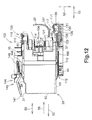
- a printer 10 as a recording apparatus is for recording an image by selectively discharging ink droplets onto a recording sheet on the basis of the inkjet recording method.
- the printer 10 includes an ink supply device 100.
- the ink supply device 100 is provided with a cartridge installation portion 110.
- the cartridge installation portion 110 can install therein an ink cartridge 30.
- the cartridge installation portion 110 is provided with an externally opened opening 112 in one surface thereof. The ink cartridge 30 is inserted into or removed from the cartridge installation portion 110 via the opening 112.
- the ink cartridge 30 accumulates therein ink usable in the printer 10. Installed in the cartridge installation portion 110, the ink cartridge 30 is connected to a recording head 21 by an ink tube 20.
- the recording head 21 is provided with a sub tank 28.
- the sub tank 28 temporarily accumulates therein the ink supplied through the ink tube 20.
- the recording head 21 selectively discharges, from a nozzle 29, the ink supplied from the sub tank 28.
- a recording sheet fed and conveyed from a sheet-feeding tray 15 to a conveying path 24 by a sheet-feeding roller 23 is conveyed onto a platen 26 by a conveying roller pair 25.
- the recording head 21 selectively discharges the ink onto the recording sheet passing over the platen 26. Thereby, an image is recorded on the recording sheet.
- the recording sheet having passed the platen 26 is discharged by a discharging roller pair 22 onto a sheet-discharging tray 16 provided on the most downstream side of the conveying path 24.
- the ink cartridge 30 is a container for accumulating therein ink.
- the space formed inside the ink cartridge 30 is an ink chamber 36 for accumulating therein the ink.
- the ink chamber 36 may be formed by a body 31 forming the exterior of the ink cartridge 30, or may be formed by a member separate from the body 31.
- the ink cartridge 30 is inserted into and removed from the cartridge installation portion 110 along directions indicated by arrows 50 (hereinafter referred to as "the insertion and removal directions 50") in a standing state illustrated in Figs. 2 and 3 , i.e., a state in which a surface on the lower side in the drawings forms a bottom surface and a surface on the upper side in the drawings forms an upper surface.
- the ink cartridge 30 is inserted into and removed from the cartridge installation portion 110 in the standing state.
- This standing state corresponds to an installation posture.
- the direction in which the ink cartridge 30 is installed into the cartridge installation portion 110 is an installation direction 56, and the direction in which the ink cartridge 30 is removed from the cartridge installation portion 110 is a removal direction 55.
- height directions 52 in the standing state correspond to gravity directions. That is, the ink cartridge 30 is inserted into the cartridge installation portion 110 along the insertion and removal directions 50, and is removed from the cartridge installation portion 110 along the insertion and removal directions 50.
- the ink cartridge 30 includes the body 31 having a substantially rectangular parallelepiped shape.
- the body 31 has a flat shape thin in width directions (left and right directions) 51 and wider in the height directions 52 and depth directions (front and rear directions) 53 than in the width directions 51.
- a wall of the body 31 located on the front side in the installation direction 56 when the ink cartridge 30 is installed into the cartridge installation portion 110 is a front wall 40, and a wall of the body 31 located on the rear side in the installation direction 56 is a rear wall 42.
- the front wall 40 and the rear wall 42 face each other in the insertion and removal directions 50.
- the front wall 40 and the rear wall 42 are respectively demarcated by four walls, which include a pair of side walls extending in the insertion and removal directions 50, an upper wall 39 connecting the side walls, the front wall 40, and the rear wall 42, and extending from the upper end of the front wall 40 to the upper end of the rear wall 42, and a lower wall 41 extending from the lower end of the front wall 40 to the lower end of the rear wall 42.
- the insertion and removal directions 50 are parallel to the depth directions 53.
- the front wall 40 corresponds to a front surface.
- the rear wall 42 corresponds to a rear surface.
- the upper wall 39 corresponds to an upper surface.
- the lower wall 41 corresponds to a bottom surface.
- a portion of the front wall 40 of the body 31 near the center thereof in the height directions 52 is provided with a remaining amount detection unit 33.
- the remaining amount detection unit 33 is located further rearward in the installation direction 56 than the leading end in the installation direction 56 of a rib 48 of a later-described first projection 45, the leading end in the installation direction 56 of a second projection 46, and a detected element 49.
- the remaining amount detection unit 33 is formed into a box shape having an opening in one side thereof to communicate with the ink chamber 36. Further, the remaining amount detection unit 33 has a pair of walls formed of a light-transmissive resin transmitting therethrough light emitted from an optical sensor 114 (see Fig. 4 ).
- a hollow space is formed between a pair of left and right walls of the remaining amount detection unit 33 so as to accumulate therein ink.
- An indicator portion 62 of a sensor arm 60 is located between the pair of left and right walls of the remaining amount detection unit 33.
- the sensor arm 60 includes the indicator portion 62 and a floating portion 63 respectively provided to opposite ends of a plate-like arm body 61.
- the sensor arm 60 is rotatably supported by a support shaft 64 extending along the width directions 51.
- the sensor arm 60 can shift the posture thereof between a lower posture in which the indicator portion 62 is located on the lower side in the gravity directions of the remaining amount detection unit 33 and an upper posture in which the indicator portion 62 is located on the upper side in the gravity directions of the remaining amount detection unit 33.
- Fig. 3 illustrates a state in which a predetermined amount or more of ink is present and the indicator portion 62 takes the lower posture.
- the remaining amount detection unit 33 shifts between a state of allowing the transmission of a predetermined amount or more of infrared light from the optical sensor 114 provided to the cartridge installation portion 110 and a state of blocking or attenuating the infrared light to be less than the predetermined amount. If the indicator portion 62 takes the upper posture, the remaining amount detection unit 33 allows the transmission of the infrared light. If the indicator portion 62 takes the lower posture, the remaining amount detection unit 33 blocks or attenuates the infrared light. It is determined, in accordance with this light-transmitting state of the remaining amount detection unit 33, that the remaining ink amount in the ink chamber 36 has decreased to be less than a predetermined amount.
- the remaining amount detection unit 33 may not include the sensor arm 60.
- a light-emitting element 118 and a light-receiving element 119 face each other in the horizontal direction, as described later. Further, the light emitted from the light-emitting element 118 is received by the light-receiving element 119.
- the configuration may be such that the infrared light emitted from the light-emitting element 118 is blocked or attenuated in a state in which the ink is present in the remaining amount detection unit 33, and that a predetermined amount or more of the infrared light emitted from the light-emitting element 118 is transmitted in a state in which the ink is absent in the remaining amount detection unit 33.
- the remaining amount detection unit 33 may be formed by a soft film. That is, the configuration may be such that, when the ink is present in the remaining amount detection unit 33, the film inflates and a rotatable lever comes into contact with this film to be held at a position at which the lever blocks the infrared light, and that, when the ink is absent in the remaining amount detection unit 33, the film deflates and the rotatable lever rotates downward or upward to rotate to a position at which the lever does not block the infrared light.
- the configuration may be such that the infrared light emitted from the light-emitting element 118 is reflected so as not to reach the light-receiving element 119 in the state in which the ink is present in the remaining amount detection unit 33, and that the infrared light emitted from the light-emitting element 118 is reflected so as to reach the light-receiving element 119 in the state in which the ink is absent in the remaining amount detection unit 33.
- a portion of the front wall 40 of the body 31 above the remaining amount detection unit 33 is formed with an opening 34 piecing through the front wall 40 in the depth directions 53, and an air communication port 32 is provided closer to the rear wall 42 in the insertion and removal directions 50 than the opening 34.
- the air communication port 32 is a through-hole piecing through a wall forming the ink chamber 36 in the depth directions 53. Through the air communication port 32, the air space in the ink chamber 36 and the atmosphere can communicate with each other.
- the air communication port 32 is configured to be openable and closable by an air communication valve 80. If the air communication port 32 is opened, the air pressure in the ink chamber 36 maintained under negative pressure becomes the outside air pressure.
- This air communication port 32 is not necessarily required to be provided on the side of the front wall 40, and the location thereof is not limited as long as the location allows the communication between the interior and the exterior of the ink chamber 36. Further, if the ink cartridge 30 is used with the interior of the ink chamber 36 maintained under negative pressure, the air communication port 32 may not necessarily be provided.
- a portion of the front wall 40 of the body 31 below the remaining amount detection unit 33 is provided with an ink supply unit 37.
- the ink supply unit 37 has a cylindrical external shape, and projects outward from the front wall 40 along the insertion and removal directions 50.
- a projecting end of the ink supply unit 37 is formed with an ink supply port 71.
- An ink flow channel 38 is formed which extends in the insertion and removal directions 50 from the ink supply port 71 through the internal space of the ink supply unit 37 to communicate with the ink chamber 36.
- the ink supply port 71 is configured to be openable and closable by an ink supply valve 70.
- the ink flows from the ink chamber 36 through the ink flow channel 38 into the ink needle 122 provided to the cartridge installation portion 110.
- the ink supply port 71 is not necessarily limited to the configuration openable and closable by the ink supply valve 70, and may be configured, for example, to be sealed by a film or the like and opened when the ink needle 122 breaks through the film upon installation of the ink cartridge 30 into the cartridge installation portion 110.
- a portion of the upper wall 39 of the body 31 near the center thereof in the depth directions 53 is formed with an engaged portion 43.
- the engaged portion 43 is a projection including a planar surface extending in the width directions 51 and the height directions 52 of the ink cartridge 30.
- the engaged portion 43 is engaged with a later-described locking lever 145 in the state in which the ink cartridge 30 is installed in the cartridge installation portion 110. This engaged portion 43 receives biasing force for pushing out the ink cartridge 30 in the removal direction 55.
- the body 31 is provided with the first projection 45 and the second projection 46.
- the first projection 45 is provided to the upper end of the front wall 40 of the body 31 to extend from the front wall 40 along a direction away from the rear wall 42 (the installation direction 56) in a direction away from the ink chamber 36.
- the width of the first projection 45 is the same as the width of the front wall 40.
- the first projection 45 projects from the front wall 40 in the direction away from the rear wall 42 (the installation direction 56).
- the leading end of the first projection 45 projects further forward in the direction away from the rear wall 42 (the installation direction 56) than the ink supply port 71 forming the leading end of the ink supply unit 37.
- this first projection 45 has the same width as the width of the front wall 40, but may be formed into a plate shape having a narrower width (length, breadth) than the width of the front wall 40.
- the center in the width directions 51 of the first projection 45 is formed with a groove 47 extending in the depth directions 53.
- the groove 47 is upwardly open in the height directions 52 in the first projection 45.
- a cross-section of the groove 47 taken along the height directions 52 has a concave shape. Further, the leading end of the groove 47 in the direction away from the ink chamber 36 is open.
- the center in the width directions 51 of the bottom surface of the groove 47 is provided with the rib 48 extending in the height directions 52 and the depth directions 53.
- the rib 48 stands upward from the bottom surface of the groove 47.
- Two side surfaces of the rib 48 in the width directions 51 respectively face and are parallel to a pair of side surfaces of the groove 48 facing each other in the width directions 51.
- the rib 48 is for blocking or attenuating light traveling in the width directions 51, and can be detected by an optical sensor 116.
- the dimension by which the rib 48 of the first projection 45 projects from the front wall 40 in the direction away from the rear wall 42 (the installation direction 56) is changed in accordance with the type of the ink cartridge 30.
- the type of the ink cartridge 30 refers to, for example, the difference in color or component of the ink or the difference in amount of the ink initially accumulated in the ink chamber 36.
- the rib 48 corresponds to a first detected portion and a first light-blocking portion.
- the first projection 45 corresponds to a first projecting portion. The first projecting portion may be formed solely by the rib 48.
- the second projection 46 is provided to the lower end of the front wall 40 of the body 31. Therefore, the second projection 46 is located below the ink supply unit 37.
- the width of the second projection 46 is the same as the width of the front wall 40.
- the second projection 46 projects from the front wall 40 in the direction away from the rear wall 42 (the installation direction 56).
- the leading end of the second projection 46 projects further forward in the direction away from the rear wall 42 (the installation direction 56) than the ink supply port 71 forming the leading end of the ink supply unit 37.
- the dimension by which the second projection 46 projects from the front wall 40 in the direction away from the rear wall 42 (the installation direction 56) is changed in accordance with the type of the ink cartridge 30.
- the type of the ink cartridge 30 refers to, for example, the difference in color or component of the ink or the difference in amount of the ink initially accumulated in the ink chamber 36.
- the second projection 46 corresponds to a second detected portion, a second projecting portion, and a second light-blocking portion. In the present embodiment, the second projection 46 is indirectly detected in the cartridge installation portion 110.
- the detected element 49 which attenuates or blocks the infrared light traveling in the width directions 51 is provided to the front wall 40 of the body 31 between the first projection 45 and the second projection 46 in the height directions 52 and in front of the remaining amount detection unit 33 in the direction away from the rear wall 42 (the installation direction 56).
- the detected element 49 is approximately the same in width as the remaining amount detection unit 33 in the width directions 51. This width has a dimension allowing the detected element 49 to enter between the light-emitting element 118 and the light-receiving element 119 of the optical sensor 114 (see Fig. 4 ).
- the detected element 49 corresponds to a third detected portion and a third light-blocking portion.
- the detected element 49 may be formed by a light-transmissive resin as a part of the remaining amount detection unit 33.
- the detected element 49 has a thickness in the width directions 51 sufficient to attenuate the infrared light.
- this light-transmissive resin may have a thickness sufficient to attenuate or reflect the infrared light, or may contain a coloring agent.
- the detected element 49 and the remaining amount detection unit 33 are located to be separate from each other with a predetermined gap formed therebetween in the depth directions 53. In this gap, the infrared light traveling in the width directions 51 is transmitted without being attenuated to be less than a predetermined amount.
- the dimension of the detected element 49 along the depth directions 53 is changed in accordance with the type of the ink cartridge 30.
- the type of the ink cartridge 30 refers to, for example, the difference in color or component, such as pigment or dye, of the ink or the difference in amount of the ink initially accumulated in the ink chamber 36.
- All of the first projection 45, the second projection 46, and the detected element 49 project further in the direction away from the rear wall 42 (the installation direction 56) than the remaining amount detection unit 33. That is, in the ink cartridge 30, the first projection 45, the second projection 46, and the detected element 49 are located further forward in the installation direction 56 than the remaining amount detection unit 33, and the remaining amount detection unit 33 is located closer to the rear wall 42 (the rear side in the installation direction 56) than the first projection 45, the second projection 46, and the detected element 49. Both of the remaining amount detection unit 33 and the ink supply port 71 are located between the first projection 45 and the second projection 46 in the height directions 52.
- the upper wall 39 of the body 31 is provided with a guide portion 35 extending in the depth directions 53.
- the guide portion 35 is formed by a rib or a projecting piece projecting upward from the upper wall 39.
- the distance between a pair of side walls of the guide portion 35 facing each other in the width directions 51 is shorter than the distance between a pair of side walls of the body 31 facing each other in the width directions 51. That is, the dimension in the width directions 51 of the guide portion 35 is less than the dimension in the width directions 51 of the body 31.
- the lower wall 41 of the body 31 is provided with a guide portion 44 extending in the depth directions 53.
- the guide portion 44 is formed by a rib or a projecting piece projecting downward from the lower wall 41.
- the distance between a pair of side walls of the guide portion 44 facing each other in the width directions 51 is shorter than the distance between a pair of side walls of the body 31 facing each other in the width directions 51. That is, the dimension in the width directions 51 of the guide portion 44 is less than the dimension in the width directions 51 of the body 31.
- the guide portions 35 and 44 are inserted and moved in later-described guide grooves 109 when the ink cartridge 30 is inserted into and removed from the cartridge installation portion 110.
- the ink supply device 100 is provided to the printer 10.
- the ink supply device 100 is for supplying ink to the recording head 21 included in the printer 10.
- the ink supply device 100 includes the cartridge installation portion 110 capable of installing therein the ink cartridge 30.
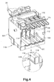
- Fig. 1 illustrates the state in which the ink cartridge 30 is installed in the cartridge installation portion 110.
- a case 101 forming a casing of the cartridge installation portion 110 includes the opening 112 on the front side of the printer 10.
- the ink cartridge 30 is inserted into and removed from the case 101 via the opening 112.
- the ink cartridge 30 is guided in the insertion and removal directions 50 as the guide portion 35 is inserted into the guide groove 109 provided to a ceiling surface defining a ceiling portion of the internal space of the case 101 and the guide portion 44 is inserted into the guide groove 109 provided to a bottom surface defining a bottom portion of the internal space of the case 101.
- the case 101 is capable of accommodating four ink cartridges 30 corresponding to respective colors of cyan, magenta, yellow, and black.
- the case 101 is provided with three plates 102 for dividing the internal space thereof into four vertically long spaces.
- the ink cartridges 30 are accommodated in the respective spaces divided by these plates 102.
- the plates 102 are provided on the side of a terminal surface of the case 101 opposite to the opening 112.
- each of the connecting portions 103 is located at a position corresponding to the ink supply unit 37 of the ink cartridge 30 installed in the case 101.
- four connecting portions 103 are provided to correspond to the four ink cartridges 30 which can be accommodated in the case 101.
- Each of the connecting portions 103 includes the ink needle 122 and a holding portion 121.
- the ink needle 122 is formed by a tubular resin needle.
- the ink needle 122 is connected to the ink tube 20 on the side of an external surface which forms the inside and the outside together with the terminal surface of the case 101.
- the individual ink tube 20 drawn to the side of the external surface, which forms the inside and the outside together with the terminal surface of the case 101, from the individual ink needle 122 is pulled upward along the external surface of the case 101, and thereafter is extended to the recording head 21 of the printer 10 so as to distribute the ink thereto.
- the holding portion 121 is formed into a cylindrical shape.
- the ink needle 122 is located at the center of the holding portion 121.
- the ink supply unit 37 is inserted inside the cylinder of the holding portion 121.
- the outer circumferential surface of the ink supply unit 37 comes into close contact with the inner circumferential surface of the cylinder of the holding portion 121.
- the ink supply unit 37 is inserted into the holding portion 121 with a predetermined gap formed therebetween.
- the ink needle 122 is inserted into the ink supply port 71 of the ink supply unit 37.
- the ink needle 122 corresponds to an ink lead-in tube.
- the terminal surface of the case 101 is provided with a sensor unit 104 above the connecting portions 103 in the gravity directions.
- the sensor unit 104 includes a substrate 113 and the optical sensor 114.
- the sensor unit 104 is configured with the optical sensor 114 installed on the substrate 113.
- the sensor unit 104 is provided with four optical sensors 114. These four optical sensors 114 correspond to the four ink cartridges 30 which can be accommodated in the case 101.
- the four optical sensors 114 are arranged in a line in the width directions of the case 101 (corresponding to the width directions 51) between the plates 102.
- Each of the optical sensors 114 includes the light-emitting element 118 such as an LED and the light-receiving element 119 such as a phototransistor.
- the light-emitting element 118 and the light-receiving element 119 are surrounded by a casing.
- the optical sensor 114 has a horseshoe-like external shape formed by the casing.
- the light-emitting element 118 is capable of emitting light from the casing in one direction.
- the light-receiving element is capable of receiving the light emitted to the casing from one direction.
- the thus configured light-emitting element 118 and light-receiving element 119 are located in the horseshoe-shaped casing to face each other with a predetermined gap formed therebetween.
- the remaining amount detection unit 33 and the detected element 49 of the ink cartridge 30 can enter the space between the light-emitting element 118 and the light-receiving element 119.
- the optical sensor 114 can detect a change in the transmitted light amount caused by the remaining amount detection unit 33 or the detected element 49.
- This optical sensor 114 corresponds to a third sensor.
- the optical path from the light-emitting element 118 to the light-receiving element 119 in the optical sensor 114 corresponds to a third detection position.
- the terminal surface side of the ceiling surface of the case 101 is provided with a sensor unit 105.
- the sensor unit 105 includes a substrate 115 and the optical sensor 116.
- the sensor unit 105 is configured with the optical sensor 116 installed on the substrate 115.
- the sensor unit 105 is provided with four optical sensors 116. These four optical sensors 116 correspond to the four ink cartridges 30 which can be accommodated in the case 101.
- the four optical sensors 116 are arranged in a line in the width directions of the case 101 (corresponding to the width directions 51) between the plates 102.
- the rib 48 of the first projection 45 enters the optical path of the optical sensor 116.
- the optical sensor 116 includes a light-emitting element and a light-receiving element, and thus description of a detailed configuration of the optical sensor 116 will be omitted here.
- the optical sensor 116 corresponds to a first sensor. Further, the optical path from the light-emitting element to the light-receiving element in the optical sensor 116 corresponds to a first detection position.
- a slide member 135 is located in a space 130 formed on the lower end side of a terminal surface of the cartridge installation portion 110.
- four slide members 135 are provided to correspond to the four ink cartridges 30 which can be accommodated in the case 101.
- the space 130 communicates with the internal space of the cartridge installation portion 110.
- the slide member 135 is slidably supported along the insertion and removal directions 50 by a support rod 133 extending along the insertion and removal directions 50 in the space 130.
- the slide member 135 has a substantially rectangular parallelepiped external shape.
- the upper end of the slide member 135 is provided with a rib 136 extending along the insertion and removal directions 50.
- the slide member 135 is located in an insertion path of the second projection 46 of the ink cartridge 30, and can come into contact with the second projection 46.
- the slide member 135 corresponds to a moving member and a biasing member.
- the space 130 is provided with a coil spring 139.
- the coil spring 139 is for elastically biasing the ink cartridge 30 to the opening 112 side for the slide member 135, i.e., in the direction in which the ink cartridge 30 is removed from the cartridge installation portion 110, i.e., toward the opening 112.
- the coil spring 139 is fit onto the support rod 133 extending along the insertion and removal directions 50 in the space 130, and is interposed between the slide member 135 and a terminal wall 131 defining a terminal end of the space 130.
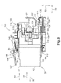
- the slide member 135 When the coil spring 139 has a natural length, i.e., when the slide member 135 is not applied with external force, the slide member 135 is located at a predetermined position on the side of the opening 112 (a first position, see Fig. 8 ). In the process of insertion of the ink cartridge 30 into the cartridge installation portion 110, the second projection 46 of the ink cartridge 30 comes into contact with the slide member 135, and the slide member 135 is pressed toward the terminal wall 131 of the space 130. Thereby, the coil spring 139 is contracted, and the slide member 135 is slid to a position on the side of the terminal wall 131 (a second position, see Fig. 6 ). The contracted coil spring 139 biases the ink cartridge 30 in the removal direction 55 via the slide member 135.
- the terminal surface of the case 101 is provided with a sensor unit 107 below the connecting portions 103 in the gravity directions and above the slide members 135 in the gravity directions.
- the sensor unit 104 includes a substrate 111 and the optical sensor 117.
- the sensor unit 107 is configured with the optical sensor 117 installed on the substrate 111.
- the sensor unit 107 is provided with four optical sensors 117. These four optical sensors 117 correspond to the four ink cartridges 30 which can be accommodated in the case 101. In other words, the four optical sensors 117 correspond to four slide members 135.
- the four optical sensors 117 are arranged in a line in the width directions of the case 101 (corresponding to the width directions 51) on the upper side of the space 130.
- the slide member 135 is slid toward the terminal wall 131 of the space 130, and the rib 136 enters the optical path (a detection position) of the optical sensor 117 and can be detected by the optical sensor 117.
- the optical sensor 117 includes a light-emitting element and a light-receiving element, and thus description of a detailed configuration of the optical sensor 117 will be omitted here.
- the optical sensor 117 corresponds to a second sensor. Further, the optical path from the light-emitting element to the light-receiving element in the optical sensor 117 corresponds to a second detection position.
- the detection position of the optical sensor 114 (the third detected position) is located further rearward in the installation direction 56 than both of the respective detection positions of the optical sensors 116 and 117 (the first detection position and the second detection position).
- the case 101 is provided with the locking lever 145.
- the locking lever 145 is for maintaining, against the biasing force of the coil spring 139, the ink cartridge 30 installed in the cartridge installation portion 110 to be in the installed state.
- the locking lever 145 is provided above the opening 112 of the case 101.
- four locking levers 145 are provided to correspond to the four ink cartridges 30 which can be installed in the case 101.
- the entire locking lever 145 is formed into an arm shape. A portion of the locking lever 145 near the center thereof is provided with a support shaft 147. This support shaft 147 is supported by the case 101. Thereby, the locking lever 145 is supported to be rotatable around the support shaft 147 above the opening 112 of the case 101.
- the locking lever 145 is roughly divided into an operation portion 149 and an engaging portion 146.
- the operation portion 149 projects outward from the opening 112 of the case 101.
- the operation portion 149 is a portion subjected to the operation for rotating the locking lever 145.
- the engaging portion 146 is embedded in the case 101. The engaging portion 146 can engage with the engaged portion 43 of the ink cartridge 30.
- the rotation position of the locking lever 145, at which the engaging portion 146 can engage with the engaged portion 43, is referred to as a locking position (a first posture), and the position at which the engaging portion 146 does not engage with the engaged portion 43 (see Fig. 8 ) is referred to as an unlocking position (a second posture).
- the locking lever 145 corresponds to a locking member.
- the locking lever 145 is attached with a coil spring 148.
- the locking lever 145 is biased toward the locking position by the coil spring 148. If the operation portion 149 of the locking lever 145 at the locking position is pushed down in the gravity directions, the locking lever 145 is rotated from the locking position to the unlocking position.
- control unit 90 With reference to Fig. 7 , a schematic configuration of a control unit 90 will be described below.
- the control unit 90 is for controlling the overall operations of the printer 10.
- the control unit 90 is configured as a microcomputer mainly including a CPU 91, a ROM 92, a RAM 93, an EEPROM 94, and an ASIC 95.
- the ROM 92 stores a program for causing the CPU 91 to control a variety of operations of the printer 10, a program for performing later-described determination processes, and so forth.
- the RAM 93 is used as a storage area for temporarily recording data, signals, and so forth used when the CPU 91 executes the above-described programs, or as a work area for data processing.
- the EEPROM 94 stores settings, flags, and so forth which should be held even after the power-off.
- the EEPROM 94 stores data (lookup data) representing the correspondence relationship between the type of the ink cartridge 30 and the combination of output signals of the detected element 49 and the rib 136 of the slide member 135.
- the ASIC 95 is connected to the optical sensors 114, 116, and 117. Although not illustrated in Fig. 7 , the ASIC 95 is also connected to a drive circuit for driving rollers such as the sheet-feeding roller 23 and the conveying roller pair 25, an input unit for inputting an image recording instruction and so forth to the printer 10, a display unit for displaying information relating to the printer 10, and so forth.
- the optical sensors 114, 116, and 117 output an analog electrical signal (voltage signal or current signal) according to the intensity of the light received by the light-receiving element.
- the control unit 90 monitors, at predetermined timing, the electrical signal output from the optical sensors 114, 116, and 117, determines the electrical signal to be a HI-level signal if the level (voltage value or current value) of the electrical signal is equal to or higher than a predetermined threshold value, and determines the electrical signal to be a LOW-level signal if the level of the electrical signal is lower than the predetermined threshold value.
- the output signal output when the light is blocked or attenuated at each of the detection positions of the optical sensors 114, 116, and 117 is determined to be the LOW-level signal, and the output signal output when the light is not blocked or attenuated is determined to be the HI-level signal.
- the determination of the HI-level signal or the LOW-level signal is relative, and thus the type of the output signal corresponding to the level (threshold value) of the electrical signal may be reversed.
- the opening 112 of the cartridge installation portion 110 is closed by an openable and closable cover provided to the casing of the printer 10. This cover is opened when the ink cartridge 30 is installed.
- the opening and closing of the cover is detected by a sensor.
- the control unit 90 can detect that the cover has been opened. Using the opening of the cover as a trigger, the control unit 90 performs a control such that light is emitted from the optical sensors 114, 116, and 117.
- a guide surface formed at the leading end in the installation direction 56 of the guide portion 35 and tilted forward in the installation direction 56 first comes into contact with the engaging portion 146 of the locking lever 145. If the ink cartridge 30 is further inserted into the cartridge installation portion 110, the engaging portion 146 of the locking lever 145 rides on the guide portion 35. Thereby, the locking lever 145 rotates counterclockwise in Fig. 8 to move from the locking position to the unlocking position.
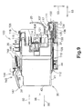
- the detected element 49 passes the detection position of the optical sensor 114 (the third detection position), as illustrated in Fig. 9 .
- the remaining amount detection unit 33 has not reached the detection position of the optical sensor 114.
- the output signal from the optical sensor 114 shifts from the HI-level signal to the LOW-level signal and then shifts again to the HI-level signal.
- the control unit 90 monitors the change in the output signal from the optical sensor 114, and stores a flag indicating that the detected element 49 has been detected, under the condition that the output signal from the optical sensor 114 has shifted from the LOW-level signal to the HI-level signal.
- the rib 48 of the first projection 45 enters the detection position of the optical sensor 116 (the first detection position), as illustrated in Fig. 9 .
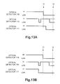
- the optical sensor 116 detects the rib 48, and thereby the output signal from the optical sensor 116 shifts from the HI-level signal to the LOW-level signal (timing T1 in (A) of Fig. 13 ).
- the control unit 90 monitors the change in the output signal from the optical sensor 116, and detects the rib 48 of the first projection 45 on the basis of the output signal being the LOW signal.
- the control unit 90 generates a trigger signal under the condition that the output signal from the optical sensor 116 has shifted from the HI-level signal to the LOW-level signal. On the basis of this trigger signal, determination is made on the output signals from the optical sensors 114 and 117.
- the second projection 46 comes into contact with the slide member 135. If the ink cartridge 30 is further inserted into the cartridge installation portion 110, the slide member located at the first position (see Fig. 8 ) is pressed toward the second position, i.e., toward the terminal wall 131 of the space 130 against the biasing force of the coil spring 139. Thereby, the rib 136 of the slide member 135 approaches the detection position of the optical sensor 117 (the second detection position).
- the rib 136 of the slide member 135 has not reached the detection position of the optical sensor 117 when the output signal from the optical sensor 116 has shifted from the HI-level signal to the LOW-level signal (timing T1), i.e., when the trigger signal has been generated. Therefore, the output signal from the optical sensor 117 is the HI-level signal (timing T1 in (A) of Fig. 13 ).
- the control unit 90 stores the respective output signals from the optical sensors 114 and 117 corresponding to the time of shift of the output signal from the optical sensor 116 from the HI-level signal to the LOW-level signal (timing T1).
- the rib 136 of the slide member 135 reaches the detection position of the optical sensor 117 (the second detection position). Thereby, the output signal from the optical sensor 117 shifts from the HI-level signal to the LOW-level signal.
- the control unit 90 detects the rib 136 of the slide member 135 on the basis of the output signal from the optical sensor 117 being the LOW-level signal.
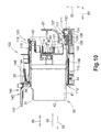
- the ink cartridge 30 is further inserted into the cartridge installation portion 110 and reaches the installation position in the cartridge installation portion 110, the remaining amount detection unit 33 reaches the detection position of the optical sensor 114 (the third detection position). Further, the ink needle 122 is inserted into the ink supply port 71 of the ink supply unit 37 to open the ink supply port 71. In this installed state, the ink accumulated in the ink chamber 33 can be supplied to the ink tube 20 through the ink needle 122.
- the engaged portion 43 passes the engaging portion 146 of the locking lever 145 in the installation direction 56. Thereby, the engaging portion 146 of the locking lever 145 is not supported by the guide portion 35. As a result, the locking lever 145 rotates clockwise in Fig. 10 , and the engaging portion 146 engages with the engaged portion 43. Owing to this engagement between the engaging portion 146 and the engaged portion 43, the ink cartridge 30 is held at the installation position against the biasing force received from the slide member 135 in the removal direction 55. Thereby, the installation of the ink cartridge 30 into the cartridge installation portion 110 is completed.
- the control unit 90 determines the type of the ink cartridge 30 under the condition that the rib 48 of the first projection 45 and the rib 139 of the slide member 135 have been detected, i.e., under the condition that the respective output signals from the optical sensors 116 and 117 are both the LOW signal. This determination of the type is performed on the basis of the output signal from the optical sensor 117 and the presence or absence of the flag at the time of shift of the output signal from the optical sensor 116 from the HI-level signal to the LOW-level signal (timing T1).
- the output signal from the optical sensor 114 shifts from the LOW-level signal to the HI-level signal before the shift of the output signal from the optical sensor 116 (timing T1) (see (A) and (B) of Fig. 13 ).
- the flag is stored in the control unit 90.
- the dimension of the detected element 49 along the insertion and removal directions 50 is long, as illustrated in Fig.
- the output signal from the optical sensor 114 shifts from the LOW-level signal to the HI-level signal after the shift of the output signal from the optical sensor 116 (timing T1).
- the flag is not stored in the control unit 90 (see (A) and (B) of Fig. 14 ) .
- the output signal from the optical sensor 117 corresponding to the time of shift of the output signal from the optical sensor 116 is the HI-level signal (see (A) of Fig. 13 and (B) of Fig. 14 ).
- the output signal from the optical sensor 117 corresponding to the time of shift of the output signal from the optical sensor 116 is the LOW-level signal (see (B) of Fig. 13 and (A) of Fig. 14 ).
- the type of the ink cartridge 30 is associated with the presence or absence of the flag and the output signal from the optical sensor 117 described above, and the associations are stored in the control unit 90 as lookup data.
- the respective output signals from the optical sensors 114, 116, and 117 are as illustrated in (A) of Fig. 13 , and the flag is stored at the timing T1. Therefore, the control unit 90 determines that the ink cartridge 30 accumulates therein color ink. Further, the output signal from the optical sensor 117 is the HI-level signal. Therefore, the control unit 90 determines that the ink cartridge 30 contains a normal amount as the initial ink amount accumulated in the ink chamber 36.
- the respective output signals from the optical sensors 114, 116, and 117 are as illustrated in (B) of Fig. 13 , and the flag is stored at the timing T1. Therefore, the control unit 90 determines that the ink cartridge 30 accumulates therein color ink. Further, the output signal from the optical sensor 117 is the HI-level signal. Therefore, the control unit 90 determines that the ink cartridge 30 contains a large amount as the initial ink amount accumulated in the ink chamber 36.
- the ink cartridge 30 contains a normal amount or a large amount is a relative concept. Further, the amount of the ink which can be accumulated in the ink chamber 36 may vary in accordance with a change in dimension in the width directions 51 of the ink cartridge 30. Further, the normal amount and the large amount may be set in accordance with a change in amount of the ink initially filling ink cartridges 30 including ink chambers 36 having the same dimension in the width directions 51 and the same capacity. Further, the amount of the ink initially filling an ink cartridge 30 packaged together with the printer 10 is larger than the initial ink amount in a replacement ink cartridge 30. This is for the following reason.
- the tube 20 and the ink flow channel from the tube 20 to the recording head 21 are not filled with ink.
- the program of the control unit 90 is set to perform a suction (purging) operation upon initial power-on of the printer 10 after the purchase.
- the ink cartridge 30 packaged together with the printer 10 is filled with ink increased by the ink amount consumed by this initial suction operation.
- the respective output signals from the optical sensors 114, 116, and 117 are as illustrated in (A) of Fig. 14 , and the flag is not stored at the timing T1. Therefore, the control unit 90 determines that the ink cartridge 30 accumulates therein black ink. Further, the output signal from the optical sensor 117 is the LOW-level signal. Therefore, the control unit 90 determines that the ink cartridge 30 contains a normal amount as the initial ink amount accumulated in the ink chamber 36.
- the control unit 90 determines that the ink cartridge 30 accumulates therein black ink. Further, the output signal from the optical sensor 117 is the HI-level signal. Therefore, the control unit 90 determines that the ink cartridge 30 contains a large amount as the initial ink amount accumulated in the ink chamber 36.
- the control unit 90 determines whether or not the position in the cartridge installation portion 110, at which the ink cartridge 30 is installed, is the position for color ink. For example, if the control unit 90 determines that black ink is accumulated in the ink cartridge 30 installed at the position in the cartridge installation portion 110, at which an ink cartridge 30 accumulating therein color ink should be installed, the control unit 90 immediately sends an error report on the assumption that the ink cartridge 30 is not installed at an appropriate position. If the control unit 90 determines that the installed ink cartridge 30 is the predetermined type of ink cartridge 30 which should be installed, the control unit 90 permits the printer 10 to perform an image recording operation.
- control unit 90 selectively sets the amount (count number) of ink droplets which can be discharged from the recording head 21 by the ink cartridge 30, or sets the ink amount consumed in the suction operation performed upon initial power-on, depending on whether the initial amount in the ink cartridge 30 installed in the cartridge installation portion 110 is a normal amount or a large amount.
- the control unit 90 does not detect the remaining amount detection unit 33 on the basis of the output signal from one of the optical sensors 114, 116, and 117 based on the detection of one of the detected element 49, the remaining amount detection unit 33, the rib 48 of the first projection 45, and the rib 136 of the slide member 135. That is, immediately after the installation of the ink cartridge 30 into the cartridge installation portion 110, the control unit 90 does not detect the remaining amount detection unit 33.
- That the control unit 90 does not detect the remaining amount detection unit 33 refers to that the remaining amount detection unit 33 does not determine the amount of the light received from the remaining amount detection unit 33 on the basis of the output signal from the optical sensor 114, and is interpreted to include a state in which, even if the optical sensor 114 emits light to the remaining amount detection unit 33 and outputs a signal, the control unit 90 does not make any determination on the basis of the output signal.
- the light is applied to the remaining amount detection unit 33.
- the ink chamber 36 is filled with a predetermined amount or more of ink
- the light applied to the remaining amount detection unit 33 is blocked by the indicator portion 62 of the sensor arm 60. If the ink in the ink chamber 36 is reduced to be less than the predetermined amount, the sensor arm 60 rotates to prevent the light applied to the remaining amount detection unit 33 from being blocked by the indicator portion 62 of the sensor arm 60.
- the posture of the sensor arm 60 changes in accordance with the ink amount accumulated in the ink chamber 36, and the light-transmitting state of the remaining amount detection unit 33 changes in accordance with the change in posture of the sensor arm 60.
- the amount of the light received by the light-receiving element 119 varies depending on whether or not the light applied by the light-emitting element 118 is blocked by the indicator portion 62.
- the light-receiving element 119 outputs different electrical signals in accordance with this difference. That is, the optical sensor 114 outputs the LOW-level signal (the outputs from the optical sensor 114 indicated by solid lines in Figs.
- the control unit 90 determines whether or not the ink in the ink chamber 102 is less than a predetermined amount.
- the control unit 90 uses, as a trigger, a signal other than the output signals from the optical sensors 114, 116, and 117 generated in the installation process of the ink cartridge 30 described above, the control unit 90 performs the determination of the remaining amount in the ink cartridge 30 (timing T2). Further, the control unit 90 performs the determination of the remaining amount under the condition that the optical sensors 116 and 117 have detected the rib 48 of the first projection 45 and the rib 136 of the slide member 135. Whether or not the optical sensors 116 and 117 have detected the rib 48 of the first projection 45 and the rib 136 of the slide member 135 may be determined when the trigger is generated.
- the control unit 90 performs, when the cover is closed, the determination of the remaining amount in the ink cartridge 30 on the basis of the output signal from the sensor.
- the electrical signal serving as the trigger for causing the control unit 90 to perform the determination of the remaining amount in the ink cartridge 30 may be generated when the printer 10 completes the image recording on one page of recording sheet. Further, the electrical signal serving as the trigger may be generated when a cleaning operation of the recording head 21 is completed, when the printer 10 is plugged in, when the power switch of the printer 10 is turned ON, or when the printer 10 in the sleep mode returns to the operating mode, for example.
- the received light amount of the remaining amount detection unit 33 is detected by the optical sensor 114 after the detection of the rib 48 of the first projection 45 and the rib 136 of the slide member 135 moved by the second projection 46. Therefore, the rib 48 of the first projection 45, the rib 136 of the slide member 135 moved by the second projection 46, and the remaining amount detection unit 33 can be effectively and accurately detected.
- the detection position of the remaining amount detection unit 33 is further rearward in the installation direction 56 than the respective detection positions of the optical sensors 116 and 117. Therefore, even if the ink dispersed or leaking from the ink supply port 71 adheres to the first projection 45 and the second projection 46, the ink hardly adheres to the remaining amount detection unit 33 in the operation of inserting or removing the ink cartridge 30 into or from the cartridge installation portion 110.
- the detection of the remaining amount detection unit 33 is performed under the condition that the rib 48 of the first projection 45 and the rib 136 of the slide member 135 moved by the second projection 46 have been detected and the installed state of the ink cartridge 30 has been detected.
- the detection of the remaining amount detection unit 33 is performed asynchronously with the detection timing of the rib 48 of the first projection 45 and the rib 136 of the slide member 135 moved by the second projection 46.
- the optical sensor 114 detects the detected element 49 in the installation process. Therefore, the rib 48 of the first projection 45, the rib 136 of the slide member 135 moved by the second projection 46, the detected element 49, and the remaining amount detection unit 33 can be effectively and accurately detected.
- first projection 45 and the second projection 46 project further in the installation direction 56 than the ink supply port 71. Therefore, if the ink cartridge 30 falls onto the floor or the like or collides with another member, the ink supply port 71 is prevented from being opened by another member inserted thereinto and causing ink leakage. Similarly, the ink supply port 71 is prevented from being damaged.
- the detected element 49 is located to be separate from the remaining amount detection unit 33 with a space formed therebetween in the installation direction 56. Therefore, the detection of the detected element 49 and the remaining amount detection unit 33 is achieved by the single optical sensor 114.
- the remaining amount detection unit 33, the ink supply port 71, the first projection 45, the second projection 46, and the detected element 49 are located on the front wall 40 of the ink cartridge 30. Therefore, the members required for the linkage between the cartridge installation portion 110 and the ink cartridge 30 are collected on the front side in the installation direction 56.
- the movement of the slide member 135 provided to the case 101 is detected by the optical sensor 117.
- the slide member 135 may not be provided, and the second projection 46 of the ink cartridge 30 may be directly detected by the optical sensor 117.
- the detected element 49 is located further forward in the installation direction 56 than the remaining amount detection unit 33.
- the detected element 49 may be located above or below the remaining amount detection unit 33 in the height directions 52, as long as the location allows the remaining amount detection unit 33 and the detected element 49 to be detected by different optical sensors.
Landscapes
- Ink Jet (AREA)
Claims (15)
- Tintenpatrone (3 0) zum Einbauen in einem Patroneneinbauabschnitt (110), umfassend:einen Körper (31) mit einer Vorderseite in einer Einbaurichtung (56), die eine Tintenliefereinheit (37) enthält, die darin angeordnet ist und Tinte von einer Tintenkammer (36) nach außerhalb liefern kann, die darin die Tinte aufnimmt, und einer Rückseite, die so angeordnet ist, dass sie der Vorderseite zugewandt ist,wobei die Tintenpatrone gekennzeichnet ist durch:einen zweiten Erfassungsabschnitt (46), der an einer Endseite der Vorderseite vorgesehen ist, wobei der zweite Erfassungsabschnitt (46) eingerichtet ist, ein sich bewegendes Teil (135) zu bewegen, das bewegbar an dem Patroneneinbauabschnitt (110) zum Aufnehmen der Tintenpatrone (30) vorgesehen ist, und wobei der zweite Erfassungsabschnitt (46) eingerichtet ist, um von einem zweiten Sensor (117) über das sich bewegende Teil (135) an einer zweiten Erfassungsposition während eines Einbauvorgangs in den Patroneneinbauabschnitt (110) erfasst zu werden.
- Tintenpatrone nach Anspruch 1, mit:einem ersten Erfassungsabschnitt (45), der an einer anderen Endseite der vorderen Seite vorgesehen ist und der eingerichtet ist, während des Einbauvorgangs in den Patroneneinbauabschnitt (110) erfasst zu werden, und/odereinem Restbetrags-Erfassungsabschnitt (33), der näher zu der Rückseite als der erste Erfassungsabschnitt (45) und der zweite Erfassungsabschnitt (46) vorgesehen ist.
- Tintenpatrone (30) nach Anspruch 1 oder 2,
mit einem dritten Erfassungsabschnitt (49), der näher zu der hinteren Seite als der erste Erfassungsanschnitt (45) und der zweite Erfassungsabschnitt (46) und weiter nach vom in der Einbaurichtung (56) als der Restbetrags-Erfassungsabschnitt (33) vorgesehen ist und der eingerichtet ist, während des Einbauvorgangs erfasst zu werden. - Tintenpatrone (30) nach einem der Ansprüche 1 bis 3,
bei der ein erster vorstehender Abschnitt den ersten Erfassungsabschnitt (45) enthält und weiter in der Einbaurichtung (56) als der Tintenlieferabschnitt (37) vorsteht, und
bei der ein zweiter vorstehender Abschnitt den zweiten Erfassungsabschnitt (46) enthält und weiter in der Einbaurichtung (56) als der Tintenlieferabschnitt (37) vorsteht. - Tintenpatrone (30) nach Anspruch 3 oder 4,
bei der der dritte Erfassungsabschnitt (49) so angeordnet ist, dass er von dem Restbetrags-Erfassungsabschnitt (33) um einen vorbestimmten Abstand von dem Restbetrags-Erfassungsabschnitt (33) in der Einbaurichtung (56) getrennt ist. - Tintenpatrone (30) nach einem der Ansprüche 1 bis 5,
bei der der Körper (31) eine obere Oberfläche (39), die sich von einer vorderer Oberfläche (40) an der Vorderseite zu einer hinteren Oberfläche (42) an der Rückseite erstreckt, und eine Bodenoberfläche (41) gegenüber der oberen Oberfläche (39) enthält, und
bei der die obere Oberfläche (39) mit einem Eingriffsabschnitt (43) versehen ist, der eingerichtet ist, in Eingriff mit einem verriegelnden Teil (145) zu kommen, um die Bewegung des Körpers (31) gegen eine vorspannende Kraft, die den Körper (31) der in den Patroneneinbauabschnitt (110) eingebaut ist, von der vorderen Oberfläche (40) in Richtung auf die hintere Oberfläche (42) vorspannt, zu begrenzen. - Tintenpatrone (30) nach einem der Ansprüche 1 bis 6,
bei der der Restbetrags-Erfassungsabschnitt (33) eingerichtet ist, Licht da hindurch zu lassen auf der Grundlage des Betrags von Tinte, die in der Tintenkammer (36) aufgenommen ist, und
bei der das Licht, dass durch den Restbetrags-Erfassungsabschnitt (33) durchgelassen ist, erfasst wird, wenn der erste Erfassungsabschnitt (45) und der zweite Erfassungsabschnitt (46) bei dem Einbauvorgang erfasst worden sind. - Aufzeichnungsgerät (10), umfassend:einem Patroneneinbauabschnitt (110), in den eine Tintenpatrone (30) nach einem der Ansprüche 1 bis 7 in einer Einbaurichtung (56) eingebaut werden kann;wobei der Patroneneinbauabschnitt (110) aufweist:einen zweiten Sensor (117), der eingerichtet ist, den zweiten Erfassungsabschnitt (46) an einer zweiten Erfassungsposition bei dem Einbauvorgang der Tintenpatrone (30) in den Patroneneinbauabschnitt (110) zu erfassen.
- Aufzeichnungsgerät (10) nach Anspruch 8, mit:einem ersten Sensor (116), der eingerichtet ist, den ersten Erfassungsabschnitt (45) an einer ersten Erfassungsposition während des Einbauvorgangs einer Tintenpatrone (30) zu erfassen,einem dritten Sensor (114), der Licht erfasst, das durch den Restbetrags-Erfassungsabschnitt (33) einer in dem Patroneneinbauabschnitt (110) eingesetzten Tintenpatrone (30) an einer dritten Erfassungsposition weiter nach hinten in der Einbaurichtung (56) als die erste Erfassungsposition und die zweite Erfassungsposition hindurch geht, nachdem der obere Erfassungsabschnitt (45) und der untere Erfassungsabschnitt (46) einer in dem Patroneneinbauabschnitt (110) eingesetzten Tintenpatrone (30) erfasst worden sind und wenn eine vorbestimmte Zeit abgelaufen ist.
- Aufzeichnungsgerät (10) nach Anspruch 8 oder 9,
bei dem die in dem Patroneneinbauabschnitt (110) eingesetzte Tintenpatrone (30) einen dritten Erfassungsabschnitt (49) enthält, der weiter nach hinten in der Einbaurichtung (56) als der erste Erfassungsabschnitt (45) und der zweite Erfassungsabschnitt (46) vorgesehen ist und weiter nach vom in der Einbaurichtung (56) als der Restbetrags-Erfassungsabschnitt (33), und
bei dem der dritte Sensor (114) den dritten Erfassungsabschnitt (49) an der dritten Erfassungsposition während des Einbauvorgangs erfasst. - Aufzeichnungsgerät (10) nach einem der Ansprüche 8 bis 10,
bei dem ein erster vorstehender Abschnitt einer in dem Patroneneinbauabschnitt (110) eingesetzten Tintenpatrone (30) den ersten Erfassungsabschnitt (45) enthält und weiter in der Einbaurichtung (56) als der Tintenlieferabschnitt (37) vorsteht, und
bei dem ein zweiter vorstehender Abschnitt einer in dem Patroneneinbauabschnitt (110) eingesetzten Tintenpatrone (30) den zweiten Erfassungsabschnitt (46) enthält und weiter in der Einbaurichtung (56) als der Tintenlieferabschnitt (37) vorsteht. - Aufzeichnungsgerät (10) nach Anspruch 10 oder 11,
bei dem der dritte Erfassungsabschnitt (49) einer in dem Patroneneinbauabschnitt (110) eingesetzten Tintenpatrone (30) so angeordnet ist, dass er von dem Restbetrags-Erfassungsabschnitt (33) um einen vorbestimmten Abstand in der Einbaurichtung (56) getrennt ist. - Aufzeichnungsgerät (10) nach einem der Ansprüche 10 bis 12,
bei dem die in dem Patroneneinbauabschnitt (110) eingesetzte Tintenpatrone (30) den Tintenlieferabschnitt (37) enthält, der weiter nach hinten in der Einbaurichtung (56) als der erste Erfassungsabschnitt (45) und der zweite Erfassungsabschnitt (46) angeordnet ist, und der eine Tintenlieferöffnung (71) weiter nach vorn in der Einbaurichtung (56) als der dritte Erfassungsabschnitt (49) enthält und der Tinte, die in der Tintenkammer (36) aufgenommen ist, zu nach außerhalb liefert, und
bei dem der Patroneneinbauabschnitt (110) eine Tinteneinlassröhre (122) enthält, die in die Tintenlieferöffnung (71) einzuführen ist. - Aufzeichnungsgerät (10) nach einem der Ansprüche 8 bis 13,
bei dem der zweite Sensor (117) eingerichtet ist, das bewegende Teil (135) zu erfassen, das in Kontakt mit dem zweiten Erfassungsabschnitt (46) bei der Vorgang des Einbauens der Tintenpatrone (30) in den Patroneneinbauabschnitt (110) kommt und dadurch bewegbar wird von einer ersten Position zu einer zweiten Position getrennt von der ersten Position in der Einbaurichtung (56) der Tintenpatrone (30). - Aufzeichnungsgerät (10) nach einem der Ansprüche 8 bis 14,
bei dem der Patroneneinbauabschnitt (110) weiter aufweist:ein vorspannendes Teil (139), das die Tintenpatrone(30) in eine entgegen gesetzte Richtung (55) zu der Einbaurichtung (56) vorspannt, undein verriegelndes Teil (145), dessen Stellung sich verschiebt zwischen einer ersten Stellung, in der eine Bewegung der Tintenpatrone (30) in dem eingebauten Zustand gegen das Vorspannen durch das vorspannende Teil (139) in die entgegen gesetzte Richtung (55) begrenzt wird, und einer zweiten Stellung, in der es der Tintenpatrone (30) ermöglicht wird, sich in die entgegen gesetzte Richtung (55) zu bewegen,
wobei das verriegelnde Teil (145) in Eingriff mit einem Eingriffsabschnitt (43) kommt, der auf einer oberen Oberfläche (39) in der Schwerkraftrichtung (52) der Tintenpatrone (30) in dem eingebauten Zustand vorgesehen ist.
Priority Applications (5)
| Application Number | Priority Date | Filing Date | Title |
|---|---|---|---|
| ES10166371T ES2397652T3 (es) | 2010-06-17 | 2010-06-17 | Aparato de registro y cartucho de tinta |
| EP10166371A EP2397330B1 (de) | 2010-06-17 | 2010-06-17 | Tintenpatrone und Aufzeichnungsvorrichtung |
| PL10166371T PL2397330T3 (pl) | 2010-06-17 | 2010-06-17 | Urządzenie rejestrujące oraz kartridż z tuszem |
| CN2010102705672A CN102285232A (zh) | 2010-06-17 | 2010-08-31 | 记录设备和墨盒 |
| US12/893,682 US20110310190A1 (en) | 2010-06-17 | 2010-09-29 | Recording apparatus and ink cartridge |
Applications Claiming Priority (1)
| Application Number | Priority Date | Filing Date | Title |
|---|---|---|---|
| EP10166371A EP2397330B1 (de) | 2010-06-17 | 2010-06-17 | Tintenpatrone und Aufzeichnungsvorrichtung |
Publications (2)
| Publication Number | Publication Date |
|---|---|
| EP2397330A1 EP2397330A1 (de) | 2011-12-21 |
| EP2397330B1 true EP2397330B1 (de) | 2013-01-02 |
Family
ID=42711672
Family Applications (1)
| Application Number | Title | Priority Date | Filing Date |
|---|---|---|---|
| EP10166371A Revoked EP2397330B1 (de) | 2010-06-17 | 2010-06-17 | Tintenpatrone und Aufzeichnungsvorrichtung |
Country Status (5)
| Country | Link |
|---|---|
| US (1) | US20110310190A1 (de) |
| EP (1) | EP2397330B1 (de) |
| CN (1) | CN102285232A (de) |
| ES (1) | ES2397652T3 (de) |
| PL (1) | PL2397330T3 (de) |
Cited By (1)
| Publication number | Priority date | Publication date | Assignee | Title |
|---|---|---|---|---|
| DE202013004920U1 (de) | 2013-05-29 | 2013-07-16 | Artech Gmbh Design + Production In Plastic | Adaptereinrichtung für einen Drucker |
Families Citing this family (9)
| Publication number | Priority date | Publication date | Assignee | Title |
|---|---|---|---|---|
| JP2012000850A (ja) * | 2010-06-17 | 2012-01-05 | Brother Industries Ltd | インク供給装置及び画像記録装置 |
| CN103171290B (zh) * | 2011-12-22 | 2015-07-08 | 兄弟工业株式会社 | 打印流体盒、打印设备和打印流体盒的使用 |
| JP5990995B2 (ja) * | 2012-04-19 | 2016-09-14 | ブラザー工業株式会社 | 印刷流体カートリッジ |
| JP6019697B2 (ja) | 2012-04-19 | 2016-11-02 | ブラザー工業株式会社 | 印刷流体収容装置及び印刷流体供給装置 |
| CN104417070B (zh) * | 2013-09-11 | 2016-09-07 | 珠海纳思达企业管理有限公司 | 一种喷墨打印机用墨盒 |
| CN203567363U (zh) * | 2013-11-15 | 2014-04-30 | 珠海纳思达企业管理有限公司 | 一种喷墨打印机用墨盒 |
| JP6464875B2 (ja) * | 2015-03-27 | 2019-02-06 | ブラザー工業株式会社 | 液体カートリッジ及び液体消費装置 |
| JP6915272B2 (ja) * | 2016-12-28 | 2021-08-04 | ブラザー工業株式会社 | 画像記録装置 |
| CN113715520A (zh) * | 2021-08-20 | 2021-11-30 | 珠海市拓佳科技有限公司 | 解锁组件和墨盒 |
Family Cites Families (18)
| Publication number | Priority date | Publication date | Assignee | Title |
|---|---|---|---|---|
| JPH07152307A (ja) * | 1993-11-30 | 1995-06-16 | Canon Inc | プロセスカートリッジ及び画像形成装置 |
| US5777646A (en) * | 1995-12-04 | 1998-07-07 | Hewlett-Packard Company | Self-sealing fluid inerconnect with double sealing septum |
| US7237884B2 (en) * | 2001-03-30 | 2007-07-03 | Brother Kogyo Kabushiki Kaisha | Ink cartridge |
| US7029105B2 (en) * | 2002-02-15 | 2006-04-18 | Matsushita Electric Industrial Co., Ltd. | Ink-jet recording device and control method thereof |
| JP2003251819A (ja) * | 2002-03-05 | 2003-09-09 | Seiko Epson Corp | インクカートリッジ検出機構及びインクジェットプリンタ |
| TWI259149B (en) * | 2002-09-30 | 2006-08-01 | Canon Kk | Ink container and recording apparatus |
| JP4356335B2 (ja) * | 2003-03-11 | 2009-11-04 | ブラザー工業株式会社 | 液体供給装置 |
| US7334888B2 (en) * | 2003-11-25 | 2008-02-26 | Brother Kogyo Kabushiki Kaisha | Ink cartridge |
| US7350909B2 (en) * | 2004-03-04 | 2008-04-01 | Brother Kogyo Kabushiki Kaisha | Ink cartridge and inkjet printer |
| EP1772270B1 (de) * | 2005-09-29 | 2008-01-16 | Brother Kogyo Kabushiki Kaisha | Tintenpatrone |
| US7635180B2 (en) * | 2005-09-29 | 2009-12-22 | Brother Kogyo Kabushiki Kaisha | Ink cartridge |
| JP4539517B2 (ja) * | 2005-09-29 | 2010-09-08 | ブラザー工業株式会社 | インクカートリッジ |
| DE202006020616U1 (de) * | 2005-11-28 | 2009-05-28 | Brother Kogyo K.K., Nagoya | Tintenpatrone, Hauptkörper und Nachfülleinheit |
| JP4816378B2 (ja) * | 2006-09-29 | 2011-11-16 | ブラザー工業株式会社 | インクカートリッジ及びインクジェット記録システム |
| JP4591466B2 (ja) * | 2007-03-28 | 2010-12-01 | ブラザー工業株式会社 | インクカートリッジ及びインクカートリッジ収容体 |
| JP5056163B2 (ja) * | 2007-05-25 | 2012-10-24 | ブラザー工業株式会社 | インクカートリッジの判定装置及び判定方法 |
| JP2009056740A (ja) * | 2007-08-31 | 2009-03-19 | Brother Ind Ltd | インク容器収容体、及び収容体製造方法 |
| JP5266999B2 (ja) * | 2008-09-19 | 2013-08-21 | ブラザー工業株式会社 | 液体吐出装置及び液体吐出システム |
-
2010
- 2010-06-17 ES ES10166371T patent/ES2397652T3/es active Active
- 2010-06-17 EP EP10166371A patent/EP2397330B1/de not_active Revoked
- 2010-06-17 PL PL10166371T patent/PL2397330T3/pl unknown
- 2010-08-31 CN CN2010102705672A patent/CN102285232A/zh active Pending
- 2010-09-29 US US12/893,682 patent/US20110310190A1/en not_active Abandoned
Cited By (2)
| Publication number | Priority date | Publication date | Assignee | Title |
|---|---|---|---|---|
| DE202013004920U1 (de) | 2013-05-29 | 2013-07-16 | Artech Gmbh Design + Production In Plastic | Adaptereinrichtung für einen Drucker |
| EP2808169A2 (de) | 2013-05-29 | 2014-12-03 | Artech GmbH design + production in plastic | Adaptereinrichtung für einen Drucker |
Also Published As
| Publication number | Publication date |
|---|---|
| EP2397330A1 (de) | 2011-12-21 |
| PL2397330T3 (pl) | 2013-04-30 |
| US20110310190A1 (en) | 2011-12-22 |
| ES2397652T3 (es) | 2013-03-08 |
| CN102285232A (zh) | 2011-12-21 |
Similar Documents
| Publication | Publication Date | Title |
|---|---|---|
| EP2397333B1 (de) | Tintenpatrone und Aufzeichnungsvorrichtung | |
| EP2397330B1 (de) | Tintenpatrone und Aufzeichnungsvorrichtung | |
| EP2397329B1 (de) | Tintenpatrone und Aufzeichnungsvorrichtung | |
| EP2397337B1 (de) | Tintenpatrone, Satz von Tintenpatronen und Tintenpatronenbestimmungssystem | |
| JP5488239B2 (ja) | 画像記録装置 | |
| US10384459B2 (en) | Printing-fluid cartridge including electrical interface and locking surface | |
| EP2397332B1 (de) | Tintenpatrone und Aufzeichnungsvorrichtung | |
| RU2407644C1 (ru) | Чернильный картридж, набор чернильных картриджей и система определения чернильного картриджа | |
| US8246151B2 (en) | Liquid supply devices | |
| JP2013049169A (ja) | 印刷流体カートリッジ及び記録装置 | |
| DK2045079T4 (en) | The ink cartridge determination system | |
| JP4816378B2 (ja) | インクカートリッジ及びインクジェット記録システム | |
| JP7114872B2 (ja) | 液体排出装置 | |
| US20110267388A1 (en) | Liquid cartridge for image forming device | |
| EP2517885A1 (de) | Flüssigkeitskartusche für eine Bilderzeugungsvorrichtung | |
| JP7124613B2 (ja) | 液体排出装置 | |
| JP2012000854A (ja) | インク供給装置及びインクカートリッジ | |
| JP3183798U (ja) | インク供給装置及びインクカートリッジ | |
| US7455381B2 (en) | Inkjet recording apparatus and ink management method for an inkjet recording apparatus | |
| JP3183795U (ja) | インク供給装置及びインクカートリッジ | |
| JP7180099B2 (ja) | 液体排出装置 | |
| JP3183788U (ja) | インク供給装置、記録装置及びインクカートリッジ | |
| JP2012000852A (ja) | インク供給装置、記録装置及びインクカートリッジ | |
| JP3194163U (ja) | 印刷流体カートリッジ及び記録装置 | |
| JP2012000853A (ja) | インク供給装置及びインクカートリッジ |
Legal Events
| Date | Code | Title | Description |
|---|---|---|---|
| AK | Designated contracting states |
Kind code of ref document: A1 Designated state(s): AL AT BE BG CH CY CZ DE DK EE ES FI FR GB GR HR HU IE IS IT LI LT LU LV MC MK MT NL NO PL PT RO SE SI SK SM TR |
|
| AX | Request for extension of the european patent |
Extension state: BA ME RS |
|
| PUAI | Public reference made under article 153(3) epc to a published international application that has entered the european phase |
Free format text: ORIGINAL CODE: 0009012 |
|
| 17P | Request for examination filed |
Effective date: 20120423 |
|
| GRAP | Despatch of communication of intention to grant a patent |
Free format text: ORIGINAL CODE: EPIDOSNIGR1 |
|
| GRAS | Grant fee paid |
Free format text: ORIGINAL CODE: EPIDOSNIGR3 |
|
| GRAA | (expected) grant |
Free format text: ORIGINAL CODE: 0009210 |
|
| AK | Designated contracting states |
Kind code of ref document: B1 Designated state(s): AL AT BE BG CH CY CZ DE DK EE ES FI FR GB GR HR HU IE IS IT LI LT LU LV MC MK MT NL NO PL PT RO SE SI SK SM TR |
|
| REG | Reference to a national code |
Ref country code: GB Ref legal event code: FG4D |
|
| REG | Reference to a national code |
Ref country code: AT Ref legal event code: REF Ref document number: 591370 Country of ref document: AT Kind code of ref document: T Effective date: 20130115 Ref country code: CH Ref legal event code: EP |
|
| REG | Reference to a national code |
Ref country code: IE Ref legal event code: FG4D |
|
| REG | Reference to a national code |
Ref country code: DE Ref legal event code: R096 Ref document number: 602010004390 Country of ref document: DE Effective date: 20130228 |
|
| REG | Reference to a national code |
Ref country code: NL Ref legal event code: T3 |
|
| REG | Reference to a national code |
Ref country code: ES Ref legal event code: FG2A Ref document number: 2397652 Country of ref document: ES Kind code of ref document: T3 Effective date: 20130308 |
|
| REG | Reference to a national code |
Ref country code: PL Ref legal event code: T3 |
|
| REG | Reference to a national code |
Ref country code: AT Ref legal event code: MK05 Ref document number: 591370 Country of ref document: AT Kind code of ref document: T Effective date: 20130102 |
|
| PG25 | Lapsed in a contracting state [announced via postgrant information from national office to epo] |
Ref country code: SI Free format text: LAPSE BECAUSE OF FAILURE TO SUBMIT A TRANSLATION OF THE DESCRIPTION OR TO PAY THE FEE WITHIN THE PRESCRIBED TIME-LIMIT Effective date: 20130102 |
|
| REG | Reference to a national code |
Ref country code: LT Ref legal event code: MG4D |
|
| PG25 | Lapsed in a contracting state [announced via postgrant information from national office to epo] |
Ref country code: SE Free format text: LAPSE BECAUSE OF FAILURE TO SUBMIT A TRANSLATION OF THE DESCRIPTION OR TO PAY THE FEE WITHIN THE PRESCRIBED TIME-LIMIT Effective date: 20130102 Ref country code: AT Free format text: LAPSE BECAUSE OF FAILURE TO SUBMIT A TRANSLATION OF THE DESCRIPTION OR TO PAY THE FEE WITHIN THE PRESCRIBED TIME-LIMIT Effective date: 20130102 Ref country code: LT Free format text: LAPSE BECAUSE OF FAILURE TO SUBMIT A TRANSLATION OF THE DESCRIPTION OR TO PAY THE FEE WITHIN THE PRESCRIBED TIME-LIMIT Effective date: 20130102 Ref country code: NO Free format text: LAPSE BECAUSE OF FAILURE TO SUBMIT A TRANSLATION OF THE DESCRIPTION OR TO PAY THE FEE WITHIN THE PRESCRIBED TIME-LIMIT Effective date: 20130402 Ref country code: BE Free format text: LAPSE BECAUSE OF FAILURE TO SUBMIT A TRANSLATION OF THE DESCRIPTION OR TO PAY THE FEE WITHIN THE PRESCRIBED TIME-LIMIT Effective date: 20130102 Ref country code: IS Free format text: LAPSE BECAUSE OF FAILURE TO SUBMIT A TRANSLATION OF THE DESCRIPTION OR TO PAY THE FEE WITHIN THE PRESCRIBED TIME-LIMIT Effective date: 20130502 Ref country code: CZ Free format text: LAPSE BECAUSE OF FAILURE TO SUBMIT A TRANSLATION OF THE DESCRIPTION OR TO PAY THE FEE WITHIN THE PRESCRIBED TIME-LIMIT Effective date: 20130102 Ref country code: BG Free format text: LAPSE BECAUSE OF FAILURE TO SUBMIT A TRANSLATION OF THE DESCRIPTION OR TO PAY THE FEE WITHIN THE PRESCRIBED TIME-LIMIT Effective date: 20130402 |
|
| PG25 | Lapsed in a contracting state [announced via postgrant information from national office to epo] |
Ref country code: PT Free format text: LAPSE BECAUSE OF FAILURE TO SUBMIT A TRANSLATION OF THE DESCRIPTION OR TO PAY THE FEE WITHIN THE PRESCRIBED TIME-LIMIT Effective date: 20130502 Ref country code: FI Free format text: LAPSE BECAUSE OF FAILURE TO SUBMIT A TRANSLATION OF THE DESCRIPTION OR TO PAY THE FEE WITHIN THE PRESCRIBED TIME-LIMIT Effective date: 20130102 Ref country code: LV Free format text: LAPSE BECAUSE OF FAILURE TO SUBMIT A TRANSLATION OF THE DESCRIPTION OR TO PAY THE FEE WITHIN THE PRESCRIBED TIME-LIMIT Effective date: 20130102 Ref country code: GR Free format text: LAPSE BECAUSE OF FAILURE TO SUBMIT A TRANSLATION OF THE DESCRIPTION OR TO PAY THE FEE WITHIN THE PRESCRIBED TIME-LIMIT Effective date: 20130403 |
|
| PG25 | Lapsed in a contracting state [announced via postgrant information from national office to epo] |
Ref country code: HR Free format text: LAPSE BECAUSE OF FAILURE TO SUBMIT A TRANSLATION OF THE DESCRIPTION OR TO PAY THE FEE WITHIN THE PRESCRIBED TIME-LIMIT Effective date: 20130102 |
|
| PLAZ | Examination of admissibility of opposition: despatch of communication + time limit |
Free format text: ORIGINAL CODE: EPIDOSNOPE2 |
|
| PLBI | Opposition filed |
Free format text: ORIGINAL CODE: 0009260 |
|
| PG25 | Lapsed in a contracting state [announced via postgrant information from national office to epo] |
Ref country code: SK Free format text: LAPSE BECAUSE OF FAILURE TO SUBMIT A TRANSLATION OF THE DESCRIPTION OR TO PAY THE FEE WITHIN THE PRESCRIBED TIME-LIMIT Effective date: 20130102 Ref country code: RO Free format text: LAPSE BECAUSE OF FAILURE TO SUBMIT A TRANSLATION OF THE DESCRIPTION OR TO PAY THE FEE WITHIN THE PRESCRIBED TIME-LIMIT Effective date: 20130102 Ref country code: EE Free format text: LAPSE BECAUSE OF FAILURE TO SUBMIT A TRANSLATION OF THE DESCRIPTION OR TO PAY THE FEE WITHIN THE PRESCRIBED TIME-LIMIT Effective date: 20130102 Ref country code: DK Free format text: LAPSE BECAUSE OF FAILURE TO SUBMIT A TRANSLATION OF THE DESCRIPTION OR TO PAY THE FEE WITHIN THE PRESCRIBED TIME-LIMIT Effective date: 20130102 |
|
| 26 | Opposition filed |
Opponent name: CZERWONKA, ALFRED Effective date: 20131002 |
|
| PG25 | Lapsed in a contracting state [announced via postgrant information from national office to epo] |
Ref country code: CY Free format text: LAPSE BECAUSE OF FAILURE TO SUBMIT A TRANSLATION OF THE DESCRIPTION OR TO PAY THE FEE WITHIN THE PRESCRIBED TIME-LIMIT Effective date: 20130102 |
|
| PLBA | Examination of admissibility of opposition: reply received |
Free format text: ORIGINAL CODE: EPIDOSNOPE4 |
|
| PLAX | Notice of opposition and request to file observation + time limit sent |
Free format text: ORIGINAL CODE: EPIDOSNOBS2 |
|
| REG | Reference to a national code |
Ref country code: DE Ref legal event code: R026 Ref document number: 602010004390 Country of ref document: DE Effective date: 20131002 |
|
| PG25 | Lapsed in a contracting state [announced via postgrant information from national office to epo] |
Ref country code: MC Free format text: LAPSE BECAUSE OF FAILURE TO SUBMIT A TRANSLATION OF THE DESCRIPTION OR TO PAY THE FEE WITHIN THE PRESCRIBED TIME-LIMIT Effective date: 20130102 |
|
| REG | Reference to a national code |
Ref country code: IE Ref legal event code: MM4A |
|
| PLBB | Reply of patent proprietor to notice(s) of opposition received |
Free format text: ORIGINAL CODE: EPIDOSNOBS3 |
|
| PG25 | Lapsed in a contracting state [announced via postgrant information from national office to epo] |
Ref country code: IE Free format text: LAPSE BECAUSE OF NON-PAYMENT OF DUE FEES Effective date: 20130617 |
|
| REG | Reference to a national code |
Ref country code: CH Ref legal event code: PL |
|
| PG25 | Lapsed in a contracting state [announced via postgrant information from national office to epo] |
Ref country code: MT Free format text: LAPSE BECAUSE OF FAILURE TO SUBMIT A TRANSLATION OF THE DESCRIPTION OR TO PAY THE FEE WITHIN THE PRESCRIBED TIME-LIMIT Effective date: 20130102 |
|
| PG25 | Lapsed in a contracting state [announced via postgrant information from national office to epo] |
Ref country code: CH Free format text: LAPSE BECAUSE OF NON-PAYMENT OF DUE FEES Effective date: 20140630 Ref country code: LI Free format text: LAPSE BECAUSE OF NON-PAYMENT OF DUE FEES Effective date: 20140630 |
|
| PG25 | Lapsed in a contracting state [announced via postgrant information from national office to epo] |
Ref country code: SM Free format text: LAPSE BECAUSE OF FAILURE TO SUBMIT A TRANSLATION OF THE DESCRIPTION OR TO PAY THE FEE WITHIN THE PRESCRIBED TIME-LIMIT Effective date: 20130102 |
|
| RDAF | Communication despatched that patent is revoked |
Free format text: ORIGINAL CODE: EPIDOSNREV1 |
|
| PG25 | Lapsed in a contracting state [announced via postgrant information from national office to epo] |
Ref country code: TR Free format text: LAPSE BECAUSE OF FAILURE TO SUBMIT A TRANSLATION OF THE DESCRIPTION OR TO PAY THE FEE WITHIN THE PRESCRIBED TIME-LIMIT Effective date: 20130102 |
|
| REG | Reference to a national code |
Ref country code: DE Ref legal event code: R064 Ref document number: 602010004390 Country of ref document: DE Ref country code: DE Ref legal event code: R103 Ref document number: 602010004390 Country of ref document: DE |
|
| PG25 | Lapsed in a contracting state [announced via postgrant information from national office to epo] |
Ref country code: HU Free format text: LAPSE BECAUSE OF FAILURE TO SUBMIT A TRANSLATION OF THE DESCRIPTION OR TO PAY THE FEE WITHIN THE PRESCRIBED TIME-LIMIT; INVALID AB INITIO Effective date: 20100617 Ref country code: MK Free format text: LAPSE BECAUSE OF FAILURE TO SUBMIT A TRANSLATION OF THE DESCRIPTION OR TO PAY THE FEE WITHIN THE PRESCRIBED TIME-LIMIT Effective date: 20130102 Ref country code: LU Free format text: LAPSE BECAUSE OF NON-PAYMENT OF DUE FEES Effective date: 20130617 |
|
| PGFP | Annual fee paid to national office [announced via postgrant information from national office to epo] |
Ref country code: ES Payment date: 20150617 Year of fee payment: 6 Ref country code: GB Payment date: 20150526 Year of fee payment: 6 |
|
| PGFP | Annual fee paid to national office [announced via postgrant information from national office to epo] |
Ref country code: FR Payment date: 20150528 Year of fee payment: 6 Ref country code: NL Payment date: 20150616 Year of fee payment: 6 Ref country code: PL Payment date: 20150514 Year of fee payment: 6 Ref country code: IT Payment date: 20150611 Year of fee payment: 6 |
|
| RDAG | Patent revoked |
Free format text: ORIGINAL CODE: 0009271 |
|
| STAA | Information on the status of an ep patent application or granted ep patent |
Free format text: STATUS: PATENT REVOKED |
|
| PGFP | Annual fee paid to national office [announced via postgrant information from national office to epo] |
Ref country code: DE Payment date: 20150630 Year of fee payment: 6 |
|
| 27W | Patent revoked |
Effective date: 20150702 |
|
| GBPR | Gb: patent revoked under art. 102 of the ep convention designating the uk as contracting state |
Effective date: 20150702 |
|
| PG25 | Lapsed in a contracting state [announced via postgrant information from national office to epo] |
Ref country code: AL Free format text: LAPSE BECAUSE OF FAILURE TO SUBMIT A TRANSLATION OF THE DESCRIPTION OR TO PAY THE FEE WITHIN THE PRESCRIBED TIME-LIMIT Effective date: 20130102 |