EP2397311B1 - Verfahren und Vorrichtung zum Stumpfschweissen von Rohren aus thermoplastischem Kunststoff - Google Patents
Verfahren und Vorrichtung zum Stumpfschweissen von Rohren aus thermoplastischem Kunststoff Download PDFInfo
- Publication number
- EP2397311B1 EP2397311B1 EP10166105.6A EP10166105A EP2397311B1 EP 2397311 B1 EP2397311 B1 EP 2397311B1 EP 10166105 A EP10166105 A EP 10166105A EP 2397311 B1 EP2397311 B1 EP 2397311B1
- Authority
- EP
- European Patent Office
- Prior art keywords
- heating
- temperature
- phase
- pipe
- heated
- Prior art date
- Legal status (The legal status is an assumption and is not a legal conclusion. Google has not performed a legal analysis and makes no representation as to the accuracy of the status listed.)
- Active
Links
Images


Classifications
-
- B—PERFORMING OPERATIONS; TRANSPORTING
- B29—WORKING OF PLASTICS; WORKING OF SUBSTANCES IN A PLASTIC STATE IN GENERAL
- B29D—PRODUCING PARTICULAR ARTICLES FROM PLASTICS OR FROM SUBSTANCES IN A PLASTIC STATE
- B29D23/00—Producing tubular articles
- B29D23/001—Pipes; Pipe joints
- B29D23/003—Pipe joints, e.g. straight joints
-
- B—PERFORMING OPERATIONS; TRANSPORTING
- B29—WORKING OF PLASTICS; WORKING OF SUBSTANCES IN A PLASTIC STATE IN GENERAL
- B29C—SHAPING OR JOINING OF PLASTICS; SHAPING OF MATERIAL IN A PLASTIC STATE, NOT OTHERWISE PROVIDED FOR; AFTER-TREATMENT OF THE SHAPED PRODUCTS, e.g. REPAIRING
- B29C65/00—Joining or sealing of preformed parts, e.g. welding of plastics materials; Apparatus therefor
-
- B—PERFORMING OPERATIONS; TRANSPORTING
- B26—HAND CUTTING TOOLS; CUTTING; SEVERING
- B26D—CUTTING; DETAILS COMMON TO MACHINES FOR PERFORATING, PUNCHING, CUTTING-OUT, STAMPING-OUT OR SEVERING
- B26D3/00—Cutting work characterised by the nature of the cut made; Apparatus therefor
- B26D3/16—Cutting rods or tubes transversely
- B26D3/166—Trimming tube-ends
-
- B—PERFORMING OPERATIONS; TRANSPORTING
- B29—WORKING OF PLASTICS; WORKING OF SUBSTANCES IN A PLASTIC STATE IN GENERAL
- B29C—SHAPING OR JOINING OF PLASTICS; SHAPING OF MATERIAL IN A PLASTIC STATE, NOT OTHERWISE PROVIDED FOR; AFTER-TREATMENT OF THE SHAPED PRODUCTS, e.g. REPAIRING
- B29C65/00—Joining or sealing of preformed parts, e.g. welding of plastics materials; Apparatus therefor
- B29C65/02—Joining or sealing of preformed parts, e.g. welding of plastics materials; Apparatus therefor by heating, with or without pressure
- B29C65/14—Joining or sealing of preformed parts, e.g. welding of plastics materials; Apparatus therefor by heating, with or without pressure using wave energy, i.e. electromagnetic radiation, or particle radiation
-
- B—PERFORMING OPERATIONS; TRANSPORTING
- B29—WORKING OF PLASTICS; WORKING OF SUBSTANCES IN A PLASTIC STATE IN GENERAL
- B29C—SHAPING OR JOINING OF PLASTICS; SHAPING OF MATERIAL IN A PLASTIC STATE, NOT OTHERWISE PROVIDED FOR; AFTER-TREATMENT OF THE SHAPED PRODUCTS, e.g. REPAIRING
- B29C65/00—Joining or sealing of preformed parts, e.g. welding of plastics materials; Apparatus therefor
- B29C65/02—Joining or sealing of preformed parts, e.g. welding of plastics materials; Apparatus therefor by heating, with or without pressure
- B29C65/18—Joining or sealing of preformed parts, e.g. welding of plastics materials; Apparatus therefor by heating, with or without pressure using heated tools
- B29C65/20—Joining or sealing of preformed parts, e.g. welding of plastics materials; Apparatus therefor by heating, with or without pressure using heated tools with direct contact, e.g. using "mirror"
-
- B—PERFORMING OPERATIONS; TRANSPORTING
- B29—WORKING OF PLASTICS; WORKING OF SUBSTANCES IN A PLASTIC STATE IN GENERAL
- B29C—SHAPING OR JOINING OF PLASTICS; SHAPING OF MATERIAL IN A PLASTIC STATE, NOT OTHERWISE PROVIDED FOR; AFTER-TREATMENT OF THE SHAPED PRODUCTS, e.g. REPAIRING
- B29C65/00—Joining or sealing of preformed parts, e.g. welding of plastics materials; Apparatus therefor
- B29C65/02—Joining or sealing of preformed parts, e.g. welding of plastics materials; Apparatus therefor by heating, with or without pressure
- B29C65/18—Joining or sealing of preformed parts, e.g. welding of plastics materials; Apparatus therefor by heating, with or without pressure using heated tools
- B29C65/20—Joining or sealing of preformed parts, e.g. welding of plastics materials; Apparatus therefor by heating, with or without pressure using heated tools with direct contact, e.g. using "mirror"
- B29C65/2092—Joining or sealing of preformed parts, e.g. welding of plastics materials; Apparatus therefor by heating, with or without pressure using heated tools with direct contact, e.g. using "mirror" and involving the use of a facer
-
- B—PERFORMING OPERATIONS; TRANSPORTING
- B29—WORKING OF PLASTICS; WORKING OF SUBSTANCES IN A PLASTIC STATE IN GENERAL
- B29C—SHAPING OR JOINING OF PLASTICS; SHAPING OF MATERIAL IN A PLASTIC STATE, NOT OTHERWISE PROVIDED FOR; AFTER-TREATMENT OF THE SHAPED PRODUCTS, e.g. REPAIRING
- B29C65/00—Joining or sealing of preformed parts, e.g. welding of plastics materials; Apparatus therefor
- B29C65/78—Means for handling the parts to be joined, e.g. for making containers or hollow articles, e.g. means for handling sheets, plates, web-like materials, tubular articles, hollow articles or elements to be joined therewith; Means for discharging the joined articles from the joining apparatus
- B29C65/7802—Positioning the parts to be joined, e.g. aligning, indexing or centring
- B29C65/7835—Positioning the parts to be joined, e.g. aligning, indexing or centring by using stops
-
- B—PERFORMING OPERATIONS; TRANSPORTING
- B29—WORKING OF PLASTICS; WORKING OF SUBSTANCES IN A PLASTIC STATE IN GENERAL
- B29C—SHAPING OR JOINING OF PLASTICS; SHAPING OF MATERIAL IN A PLASTIC STATE, NOT OTHERWISE PROVIDED FOR; AFTER-TREATMENT OF THE SHAPED PRODUCTS, e.g. REPAIRING
- B29C66/00—General aspects of processes or apparatus for joining preformed parts
- B29C66/01—General aspects dealing with the joint area or with the area to be joined
- B29C66/02—Preparation of the material, in the area to be joined, prior to joining or welding
- B29C66/022—Mechanical pre-treatments, e.g. reshaping
-
- B—PERFORMING OPERATIONS; TRANSPORTING
- B29—WORKING OF PLASTICS; WORKING OF SUBSTANCES IN A PLASTIC STATE IN GENERAL
- B29C—SHAPING OR JOINING OF PLASTICS; SHAPING OF MATERIAL IN A PLASTIC STATE, NOT OTHERWISE PROVIDED FOR; AFTER-TREATMENT OF THE SHAPED PRODUCTS, e.g. REPAIRING
- B29C66/00—General aspects of processes or apparatus for joining preformed parts
- B29C66/01—General aspects dealing with the joint area or with the area to be joined
- B29C66/02—Preparation of the material, in the area to be joined, prior to joining or welding
- B29C66/022—Mechanical pre-treatments, e.g. reshaping
- B29C66/0224—Mechanical pre-treatments, e.g. reshaping with removal of material
- B29C66/02241—Cutting, e.g. by using waterjets, or sawing
-
- B—PERFORMING OPERATIONS; TRANSPORTING
- B29—WORKING OF PLASTICS; WORKING OF SUBSTANCES IN A PLASTIC STATE IN GENERAL
- B29C—SHAPING OR JOINING OF PLASTICS; SHAPING OF MATERIAL IN A PLASTIC STATE, NOT OTHERWISE PROVIDED FOR; AFTER-TREATMENT OF THE SHAPED PRODUCTS, e.g. REPAIRING
- B29C66/00—General aspects of processes or apparatus for joining preformed parts
- B29C66/01—General aspects dealing with the joint area or with the area to be joined
- B29C66/03—After-treatments in the joint area
- B29C66/032—Mechanical after-treatments
- B29C66/0322—Post-pressing without reshaping, i.e. keeping the joint under pressure after joining
-
- B—PERFORMING OPERATIONS; TRANSPORTING
- B29—WORKING OF PLASTICS; WORKING OF SUBSTANCES IN A PLASTIC STATE IN GENERAL
- B29C—SHAPING OR JOINING OF PLASTICS; SHAPING OF MATERIAL IN A PLASTIC STATE, NOT OTHERWISE PROVIDED FOR; AFTER-TREATMENT OF THE SHAPED PRODUCTS, e.g. REPAIRING
- B29C66/00—General aspects of processes or apparatus for joining preformed parts
- B29C66/01—General aspects dealing with the joint area or with the area to be joined
- B29C66/05—Particular design of joint configurations
- B29C66/10—Particular design of joint configurations particular design of the joint cross-sections
- B29C66/11—Joint cross-sections comprising a single joint-segment, i.e. one of the parts to be joined comprising a single joint-segment in the joint cross-section
- B29C66/114—Single butt joints
- B29C66/1142—Single butt to butt joints
-
- B—PERFORMING OPERATIONS; TRANSPORTING
- B29—WORKING OF PLASTICS; WORKING OF SUBSTANCES IN A PLASTIC STATE IN GENERAL
- B29C—SHAPING OR JOINING OF PLASTICS; SHAPING OF MATERIAL IN A PLASTIC STATE, NOT OTHERWISE PROVIDED FOR; AFTER-TREATMENT OF THE SHAPED PRODUCTS, e.g. REPAIRING
- B29C66/00—General aspects of processes or apparatus for joining preformed parts
- B29C66/01—General aspects dealing with the joint area or with the area to be joined
- B29C66/32—Measures for keeping the burr form under control; Avoiding burr formation; Shaping the burr
-
- B—PERFORMING OPERATIONS; TRANSPORTING
- B29—WORKING OF PLASTICS; WORKING OF SUBSTANCES IN A PLASTIC STATE IN GENERAL
- B29C—SHAPING OR JOINING OF PLASTICS; SHAPING OF MATERIAL IN A PLASTIC STATE, NOT OTHERWISE PROVIDED FOR; AFTER-TREATMENT OF THE SHAPED PRODUCTS, e.g. REPAIRING
- B29C66/00—General aspects of processes or apparatus for joining preformed parts
- B29C66/50—General aspects of joining tubular articles; General aspects of joining long products, i.e. bars or profiled elements; General aspects of joining single elements to tubular articles, hollow articles or bars; General aspects of joining several hollow-preforms to form hollow or tubular articles
- B29C66/51—Joining tubular articles, profiled elements or bars; Joining single elements to tubular articles, hollow articles or bars; Joining several hollow-preforms to form hollow or tubular articles
- B29C66/52—Joining tubular articles, bars or profiled elements
- B29C66/522—Joining tubular articles
- B29C66/5221—Joining tubular articles for forming coaxial connections, i.e. the tubular articles to be joined forming a zero angle relative to each other
-
- B—PERFORMING OPERATIONS; TRANSPORTING
- B29—WORKING OF PLASTICS; WORKING OF SUBSTANCES IN A PLASTIC STATE IN GENERAL
- B29C—SHAPING OR JOINING OF PLASTICS; SHAPING OF MATERIAL IN A PLASTIC STATE, NOT OTHERWISE PROVIDED FOR; AFTER-TREATMENT OF THE SHAPED PRODUCTS, e.g. REPAIRING
- B29C66/00—General aspects of processes or apparatus for joining preformed parts
- B29C66/70—General aspects of processes or apparatus for joining preformed parts characterised by the composition, physical properties or the structure of the material of the parts to be joined; Joining with non-plastics material
- B29C66/73—General aspects of processes or apparatus for joining preformed parts characterised by the composition, physical properties or the structure of the material of the parts to be joined; Joining with non-plastics material characterised by the intensive physical properties of the material of the parts to be joined, by the optical properties of the material of the parts to be joined, by the extensive physical properties of the parts to be joined, by the state of the material of the parts to be joined or by the material of the parts to be joined being a thermoplastic or a thermoset
- B29C66/739—General aspects of processes or apparatus for joining preformed parts characterised by the composition, physical properties or the structure of the material of the parts to be joined; Joining with non-plastics material characterised by the intensive physical properties of the material of the parts to be joined, by the optical properties of the material of the parts to be joined, by the extensive physical properties of the parts to be joined, by the state of the material of the parts to be joined or by the material of the parts to be joined being a thermoplastic or a thermoset characterised by the material of the parts to be joined being a thermoplastic or a thermoset
- B29C66/7392—General aspects of processes or apparatus for joining preformed parts characterised by the composition, physical properties or the structure of the material of the parts to be joined; Joining with non-plastics material characterised by the intensive physical properties of the material of the parts to be joined, by the optical properties of the material of the parts to be joined, by the extensive physical properties of the parts to be joined, by the state of the material of the parts to be joined or by the material of the parts to be joined being a thermoplastic or a thermoset characterised by the material of the parts to be joined being a thermoplastic or a thermoset characterised by the material of at least one of the parts being a thermoplastic
- B29C66/73921—General aspects of processes or apparatus for joining preformed parts characterised by the composition, physical properties or the structure of the material of the parts to be joined; Joining with non-plastics material characterised by the intensive physical properties of the material of the parts to be joined, by the optical properties of the material of the parts to be joined, by the extensive physical properties of the parts to be joined, by the state of the material of the parts to be joined or by the material of the parts to be joined being a thermoplastic or a thermoset characterised by the material of the parts to be joined being a thermoplastic or a thermoset characterised by the material of at least one of the parts being a thermoplastic characterised by the materials of both parts being thermoplastics
-
- B—PERFORMING OPERATIONS; TRANSPORTING
- B29—WORKING OF PLASTICS; WORKING OF SUBSTANCES IN A PLASTIC STATE IN GENERAL
- B29C—SHAPING OR JOINING OF PLASTICS; SHAPING OF MATERIAL IN A PLASTIC STATE, NOT OTHERWISE PROVIDED FOR; AFTER-TREATMENT OF THE SHAPED PRODUCTS, e.g. REPAIRING
- B29C66/00—General aspects of processes or apparatus for joining preformed parts
- B29C66/80—General aspects of machine operations or constructions and parts thereof
-
- B—PERFORMING OPERATIONS; TRANSPORTING
- B29—WORKING OF PLASTICS; WORKING OF SUBSTANCES IN A PLASTIC STATE IN GENERAL
- B29C—SHAPING OR JOINING OF PLASTICS; SHAPING OF MATERIAL IN A PLASTIC STATE, NOT OTHERWISE PROVIDED FOR; AFTER-TREATMENT OF THE SHAPED PRODUCTS, e.g. REPAIRING
- B29C66/00—General aspects of processes or apparatus for joining preformed parts
- B29C66/90—Measuring or controlling the joining process
- B29C66/91—Measuring or controlling the joining process by measuring or controlling the temperature, the heat or the thermal flux
- B29C66/912—Measuring or controlling the joining process by measuring or controlling the temperature, the heat or the thermal flux by measuring the temperature, the heat or the thermal flux
- B29C66/9121—Measuring or controlling the joining process by measuring or controlling the temperature, the heat or the thermal flux by measuring the temperature, the heat or the thermal flux by measuring the temperature
-
- B—PERFORMING OPERATIONS; TRANSPORTING
- B29—WORKING OF PLASTICS; WORKING OF SUBSTANCES IN A PLASTIC STATE IN GENERAL
- B29C—SHAPING OR JOINING OF PLASTICS; SHAPING OF MATERIAL IN A PLASTIC STATE, NOT OTHERWISE PROVIDED FOR; AFTER-TREATMENT OF THE SHAPED PRODUCTS, e.g. REPAIRING
- B29C66/00—General aspects of processes or apparatus for joining preformed parts
- B29C66/90—Measuring or controlling the joining process
- B29C66/91—Measuring or controlling the joining process by measuring or controlling the temperature, the heat or the thermal flux
- B29C66/914—Measuring or controlling the joining process by measuring or controlling the temperature, the heat or the thermal flux by controlling or regulating the temperature, the heat or the thermal flux
- B29C66/9141—Measuring or controlling the joining process by measuring or controlling the temperature, the heat or the thermal flux by controlling or regulating the temperature, the heat or the thermal flux by controlling or regulating the temperature
- B29C66/91431—Measuring or controlling the joining process by measuring or controlling the temperature, the heat or the thermal flux by controlling or regulating the temperature, the heat or the thermal flux by controlling or regulating the temperature the temperature being kept constant over time
-
- B—PERFORMING OPERATIONS; TRANSPORTING
- B29—WORKING OF PLASTICS; WORKING OF SUBSTANCES IN A PLASTIC STATE IN GENERAL
- B29C—SHAPING OR JOINING OF PLASTICS; SHAPING OF MATERIAL IN A PLASTIC STATE, NOT OTHERWISE PROVIDED FOR; AFTER-TREATMENT OF THE SHAPED PRODUCTS, e.g. REPAIRING
- B29C66/00—General aspects of processes or apparatus for joining preformed parts
- B29C66/90—Measuring or controlling the joining process
- B29C66/92—Measuring or controlling the joining process by measuring or controlling the pressure, the force, the mechanical power or the displacement of the joining tools
- B29C66/922—Measuring or controlling the joining process by measuring or controlling the pressure, the force, the mechanical power or the displacement of the joining tools by measuring the pressure, the force, the mechanical power or the displacement of the joining tools
- B29C66/9221—Measuring or controlling the joining process by measuring or controlling the pressure, the force, the mechanical power or the displacement of the joining tools by measuring the pressure, the force, the mechanical power or the displacement of the joining tools by measuring the pressure, the force or the mechanical power
-
- B—PERFORMING OPERATIONS; TRANSPORTING
- B29—WORKING OF PLASTICS; WORKING OF SUBSTANCES IN A PLASTIC STATE IN GENERAL
- B29C—SHAPING OR JOINING OF PLASTICS; SHAPING OF MATERIAL IN A PLASTIC STATE, NOT OTHERWISE PROVIDED FOR; AFTER-TREATMENT OF THE SHAPED PRODUCTS, e.g. REPAIRING
- B29C66/00—General aspects of processes or apparatus for joining preformed parts
- B29C66/90—Measuring or controlling the joining process
- B29C66/92—Measuring or controlling the joining process by measuring or controlling the pressure, the force, the mechanical power or the displacement of the joining tools
- B29C66/922—Measuring or controlling the joining process by measuring or controlling the pressure, the force, the mechanical power or the displacement of the joining tools by measuring the pressure, the force, the mechanical power or the displacement of the joining tools
- B29C66/9231—Measuring or controlling the joining process by measuring or controlling the pressure, the force, the mechanical power or the displacement of the joining tools by measuring the pressure, the force, the mechanical power or the displacement of the joining tools by measuring the displacement of the joining tools
-
- B—PERFORMING OPERATIONS; TRANSPORTING
- B29—WORKING OF PLASTICS; WORKING OF SUBSTANCES IN A PLASTIC STATE IN GENERAL
- B29C—SHAPING OR JOINING OF PLASTICS; SHAPING OF MATERIAL IN A PLASTIC STATE, NOT OTHERWISE PROVIDED FOR; AFTER-TREATMENT OF THE SHAPED PRODUCTS, e.g. REPAIRING
- B29C66/00—General aspects of processes or apparatus for joining preformed parts
- B29C66/90—Measuring or controlling the joining process
- B29C66/92—Measuring or controlling the joining process by measuring or controlling the pressure, the force, the mechanical power or the displacement of the joining tools
- B29C66/924—Measuring or controlling the joining process by measuring or controlling the pressure, the force, the mechanical power or the displacement of the joining tools by controlling or regulating the pressure, the force, the mechanical power or the displacement of the joining tools
- B29C66/9241—Measuring or controlling the joining process by measuring or controlling the pressure, the force, the mechanical power or the displacement of the joining tools by controlling or regulating the pressure, the force, the mechanical power or the displacement of the joining tools by controlling or regulating the pressure, the force or the mechanical power
- B29C66/92441—Measuring or controlling the joining process by measuring or controlling the pressure, the force, the mechanical power or the displacement of the joining tools by controlling or regulating the pressure, the force, the mechanical power or the displacement of the joining tools by controlling or regulating the pressure, the force or the mechanical power the pressure, the force or the mechanical power being non-constant over time
-
- B—PERFORMING OPERATIONS; TRANSPORTING
- B29—WORKING OF PLASTICS; WORKING OF SUBSTANCES IN A PLASTIC STATE IN GENERAL
- B29C—SHAPING OR JOINING OF PLASTICS; SHAPING OF MATERIAL IN A PLASTIC STATE, NOT OTHERWISE PROVIDED FOR; AFTER-TREATMENT OF THE SHAPED PRODUCTS, e.g. REPAIRING
- B29C66/00—General aspects of processes or apparatus for joining preformed parts
- B29C66/90—Measuring or controlling the joining process
- B29C66/92—Measuring or controlling the joining process by measuring or controlling the pressure, the force, the mechanical power or the displacement of the joining tools
- B29C66/924—Measuring or controlling the joining process by measuring or controlling the pressure, the force, the mechanical power or the displacement of the joining tools by controlling or regulating the pressure, the force, the mechanical power or the displacement of the joining tools
- B29C66/9241—Measuring or controlling the joining process by measuring or controlling the pressure, the force, the mechanical power or the displacement of the joining tools by controlling or regulating the pressure, the force, the mechanical power or the displacement of the joining tools by controlling or regulating the pressure, the force or the mechanical power
- B29C66/92441—Measuring or controlling the joining process by measuring or controlling the pressure, the force, the mechanical power or the displacement of the joining tools by controlling or regulating the pressure, the force, the mechanical power or the displacement of the joining tools by controlling or regulating the pressure, the force or the mechanical power the pressure, the force or the mechanical power being non-constant over time
- B29C66/92443—Measuring or controlling the joining process by measuring or controlling the pressure, the force, the mechanical power or the displacement of the joining tools by controlling or regulating the pressure, the force, the mechanical power or the displacement of the joining tools by controlling or regulating the pressure, the force or the mechanical power the pressure, the force or the mechanical power being non-constant over time following a pressure-time profile
- B29C66/92445—Measuring or controlling the joining process by measuring or controlling the pressure, the force, the mechanical power or the displacement of the joining tools by controlling or regulating the pressure, the force, the mechanical power or the displacement of the joining tools by controlling or regulating the pressure, the force or the mechanical power the pressure, the force or the mechanical power being non-constant over time following a pressure-time profile by steps
-
- B—PERFORMING OPERATIONS; TRANSPORTING
- B29—WORKING OF PLASTICS; WORKING OF SUBSTANCES IN A PLASTIC STATE IN GENERAL
- B29C—SHAPING OR JOINING OF PLASTICS; SHAPING OF MATERIAL IN A PLASTIC STATE, NOT OTHERWISE PROVIDED FOR; AFTER-TREATMENT OF THE SHAPED PRODUCTS, e.g. REPAIRING
- B29C66/00—General aspects of processes or apparatus for joining preformed parts
- B29C66/90—Measuring or controlling the joining process
- B29C66/92—Measuring or controlling the joining process by measuring or controlling the pressure, the force, the mechanical power or the displacement of the joining tools
- B29C66/924—Measuring or controlling the joining process by measuring or controlling the pressure, the force, the mechanical power or the displacement of the joining tools by controlling or regulating the pressure, the force, the mechanical power or the displacement of the joining tools
- B29C66/9261—Measuring or controlling the joining process by measuring or controlling the pressure, the force, the mechanical power or the displacement of the joining tools by controlling or regulating the pressure, the force, the mechanical power or the displacement of the joining tools by controlling or regulating the displacement of the joining tools
-
- B—PERFORMING OPERATIONS; TRANSPORTING
- B29—WORKING OF PLASTICS; WORKING OF SUBSTANCES IN A PLASTIC STATE IN GENERAL
- B29C—SHAPING OR JOINING OF PLASTICS; SHAPING OF MATERIAL IN A PLASTIC STATE, NOT OTHERWISE PROVIDED FOR; AFTER-TREATMENT OF THE SHAPED PRODUCTS, e.g. REPAIRING
- B29C66/00—General aspects of processes or apparatus for joining preformed parts
- B29C66/90—Measuring or controlling the joining process
- B29C66/92—Measuring or controlling the joining process by measuring or controlling the pressure, the force, the mechanical power or the displacement of the joining tools
- B29C66/924—Measuring or controlling the joining process by measuring or controlling the pressure, the force, the mechanical power or the displacement of the joining tools by controlling or regulating the pressure, the force, the mechanical power or the displacement of the joining tools
- B29C66/9261—Measuring or controlling the joining process by measuring or controlling the pressure, the force, the mechanical power or the displacement of the joining tools by controlling or regulating the pressure, the force, the mechanical power or the displacement of the joining tools by controlling or regulating the displacement of the joining tools
- B29C66/92651—Measuring or controlling the joining process by measuring or controlling the pressure, the force, the mechanical power or the displacement of the joining tools by controlling or regulating the pressure, the force, the mechanical power or the displacement of the joining tools by controlling or regulating the displacement of the joining tools by using stops
-
- B—PERFORMING OPERATIONS; TRANSPORTING
- B29—WORKING OF PLASTICS; WORKING OF SUBSTANCES IN A PLASTIC STATE IN GENERAL
- B29C—SHAPING OR JOINING OF PLASTICS; SHAPING OF MATERIAL IN A PLASTIC STATE, NOT OTHERWISE PROVIDED FOR; AFTER-TREATMENT OF THE SHAPED PRODUCTS, e.g. REPAIRING
- B29C66/00—General aspects of processes or apparatus for joining preformed parts
- B29C66/90—Measuring or controlling the joining process
- B29C66/92—Measuring or controlling the joining process by measuring or controlling the pressure, the force, the mechanical power or the displacement of the joining tools
- B29C66/929—Measuring or controlling the joining process by measuring or controlling the pressure, the force, the mechanical power or the displacement of the joining tools characterized by specific pressure, force, mechanical power or displacement values or ranges
- B29C66/9292—Measuring or controlling the joining process by measuring or controlling the pressure, the force, the mechanical power or the displacement of the joining tools characterized by specific pressure, force, mechanical power or displacement values or ranges in explicit relation to another variable, e.g. pressure diagrams
- B29C66/92921—Measuring or controlling the joining process by measuring or controlling the pressure, the force, the mechanical power or the displacement of the joining tools characterized by specific pressure, force, mechanical power or displacement values or ranges in explicit relation to another variable, e.g. pressure diagrams in specific relation to time, e.g. pressure-time diagrams
-
- B—PERFORMING OPERATIONS; TRANSPORTING
- B29—WORKING OF PLASTICS; WORKING OF SUBSTANCES IN A PLASTIC STATE IN GENERAL
- B29C—SHAPING OR JOINING OF PLASTICS; SHAPING OF MATERIAL IN A PLASTIC STATE, NOT OTHERWISE PROVIDED FOR; AFTER-TREATMENT OF THE SHAPED PRODUCTS, e.g. REPAIRING
- B29C66/00—General aspects of processes or apparatus for joining preformed parts
- B29C66/90—Measuring or controlling the joining process
- B29C66/94—Measuring or controlling the joining process by measuring or controlling the time
- B29C66/944—Measuring or controlling the joining process by measuring or controlling the time by controlling or regulating the time
- B29C66/9441—Measuring or controlling the joining process by measuring or controlling the time by controlling or regulating the time the time being controlled or regulated as a function of another parameter
-
- B—PERFORMING OPERATIONS; TRANSPORTING
- B29—WORKING OF PLASTICS; WORKING OF SUBSTANCES IN A PLASTIC STATE IN GENERAL
- B29C—SHAPING OR JOINING OF PLASTICS; SHAPING OF MATERIAL IN A PLASTIC STATE, NOT OTHERWISE PROVIDED FOR; AFTER-TREATMENT OF THE SHAPED PRODUCTS, e.g. REPAIRING
- B29C66/00—General aspects of processes or apparatus for joining preformed parts
- B29C66/90—Measuring or controlling the joining process
- B29C66/97—Checking completion of joining or correct joining by using indications on at least one of the joined parts
- B29C66/974—Checking completion of joining or correct joining by using indications on at least one of the joined parts by checking the bead or burr form
-
- B—PERFORMING OPERATIONS; TRANSPORTING
- B29—WORKING OF PLASTICS; WORKING OF SUBSTANCES IN A PLASTIC STATE IN GENERAL
- B29C—SHAPING OR JOINING OF PLASTICS; SHAPING OF MATERIAL IN A PLASTIC STATE, NOT OTHERWISE PROVIDED FOR; AFTER-TREATMENT OF THE SHAPED PRODUCTS, e.g. REPAIRING
- B29C2793/00—Shaping techniques involving a cutting or machining operation
- B29C2793/0081—Shaping techniques involving a cutting or machining operation before shaping
-
- B—PERFORMING OPERATIONS; TRANSPORTING
- B29—WORKING OF PLASTICS; WORKING OF SUBSTANCES IN A PLASTIC STATE IN GENERAL
- B29C—SHAPING OR JOINING OF PLASTICS; SHAPING OF MATERIAL IN A PLASTIC STATE, NOT OTHERWISE PROVIDED FOR; AFTER-TREATMENT OF THE SHAPED PRODUCTS, e.g. REPAIRING
- B29C66/00—General aspects of processes or apparatus for joining preformed parts
- B29C66/90—Measuring or controlling the joining process
- B29C66/96—Measuring or controlling the joining process characterised by the method for implementing the controlling of the joining process
- B29C66/961—Measuring or controlling the joining process characterised by the method for implementing the controlling of the joining process involving a feedback loop mechanism, e.g. comparison with a desired value
-
- B—PERFORMING OPERATIONS; TRANSPORTING
- B29—WORKING OF PLASTICS; WORKING OF SUBSTANCES IN A PLASTIC STATE IN GENERAL
- B29K—INDEXING SCHEME ASSOCIATED WITH SUBCLASSES B29B, B29C OR B29D, RELATING TO MOULDING MATERIALS OR TO MATERIALS FOR MOULDS, REINFORCEMENTS, FILLERS OR PREFORMED PARTS, e.g. INSERTS
- B29K2101/00—Use of unspecified macromolecular compounds as moulding material
- B29K2101/12—Thermoplastic materials
-
- B—PERFORMING OPERATIONS; TRANSPORTING
- B29—WORKING OF PLASTICS; WORKING OF SUBSTANCES IN A PLASTIC STATE IN GENERAL
- B29L—INDEXING SCHEME ASSOCIATED WITH SUBCLASS B29C, RELATING TO PARTICULAR ARTICLES
- B29L2023/00—Tubular articles
- B29L2023/22—Tubes or pipes, i.e. rigid
Definitions
- the invention relates to a method for welding plastic pipes made of thermoplastic material by means of butt welding, wherein the tubes are held in a coaxial position to each other by means of clamping points, by means of a planer which can be brought between the clamping points, be planed and mounted by means of heating mirror instead of the planer, be heated by touching the heating mirror, wherein a melting area is generated by the heating of the free pipe ends to be welded, which forms a bead during pressing.
- the known method for butt welding of two plastic pipes so far essentially always runs the same, whether it is performed by manual or automatic machines.
- the plastic pipes are clamped in the clamping points provided for this purpose, wherein the opposite pipe ends protrude from the clamping points and all damages and impurities are removed by removing the plane located between the two pipe ends plane and the mutual collapse of the clamping points in the direction of the rotating plane.
- the end faces of the tube ends extend at right angles to the axis of the tube and parallel to the opposite end face of the other tube end. Subsequently, the pipe ends are moved apart and the planer removed, then a heating mirror is placed between the tubes, whereupon the clamping points again go against each other to bring the end faces of the pipe ends in contact with the heating mirror.
- the matching of the tube ends takes place under a predetermined, constant pressure which is dependent on the material, the tube diameter and the wall thickness.
- the pressure which is usually generated by a hydraulic unit, is exerted on the two pipe ends or the heating mirror until beads are formed on the circumference of the pipe ends, which correspond to the predetermined dimensions.
- the pressure is reduced and maintained for a prescribed time to achieve a temperature profile required in the joining zone of the plastic pipe for welding.
- the heating mirror is removed and the pipe ends are then pressed together under a predetermined pressure and a defined period of time, so that a required penetration of the pipe ends takes place and a welding of the pipe ends is guaranteed.
- a disadvantage of such a solution is that the method requires a complex control in which a corresponding time-distance curve is stored for each diameter and each material.
- the device requires sensors or sensors for determining the tube end position which must be determined twice during a weld.
- the supernatant of the tubes is planed to a defined extent, that is, the raw supernatants are prepared for each weld to the same length, which is achieved by mechanical stops that serve as Wegbegrenzer, or by a built-in and connected to the control position measuring system, which allows the desired position to approach exactly.
- the tube projection Since, however, touching the tube projections with the heating mirror is a prerequisite for a good heat transfer, the tube projection has a length addition of up to 0.5 mm compared to the heating stop, thus a minimum matching is given, which is integrated into the phase of warming since it no longer requires a separate adjustment phase due to the temperature adjustment of the heating mirror or the adaptation of the duration of the warm-up phase to the pipe or ambient temperature.
- matching in the new method described here no longer has the same task as in the conventional DVS method.
- the heat mirror temperature is adjusted in the new method described here to the pipe temperature which corresponds to the ambient temperature.
- the ambient temperature is determined, for example, by means of a sensor and is compared in the controller with a standard value to which a heating mirror temperature is assigned. The difference between the standard value and the measured value is added to the heating mirror temperature or subtracted from the heating mirror temperature of the standard value.
- a deep Ambient temperature it requires a correspondingly higher heating mirror temperature and vice versa.
- Another possibility to adapt the welding process to the ambient temperature is that the time of the warming-up phase is lengthened or shortened accordingly. so that at a low ambient temperature or tube temperature, the Anürmphase is sufficiently extended.
- the new method described here is characterized by the shortening of the welding time, a low energy consumption and the achievement of the smallest possible bead.
- the new method described here is feasible without any pressure sensors and Wegmesssysteme, but an extension with such applications is quite thinkable and feasible.
- Fig. 1 shows the clamped in the clamping points 2 tubes 1 before planing.
- planer 3 On planer 3 are fixedly mounted planing stops 4, which allow the lengths of the pipe projections 5 to be planed exactly to measure, also it is guaranteed that each weld creates the same bead.
- the clamping points 2 are driven against the planer 3 until they pending the planing stops 4, whereby the exact tube protrusion length is defined.
- the clamping points 2 are moved apart again with the clamped tubes 1 in order to place the heating mirror 6 in place of the planer 3, as in FIG Fig. 3 shown.
- the heating mirror 6 has heating stops 7 whereby a controlled, if necessary matching is feasible.
- the heating stops 7 are formed in comparison with the planing stops 4 so that they are shorter by up to 0.5 mm, to ensure that the tube projection 5 comes into contact with the heating mirror 6 on both sides.
- Fig. 4 shows that the tube projections 5 are slightly longer than the heating stops 7, whereby the collapse of the clamping points 2 against the heating mirror 6 causes a pressure in the raw supernatant 5, until the length of the tube supernatant 5 has been reduced by the heating to the length of the heating stops 7 or . Has melted away and the clamping points 2 are present at the heating stops 7.
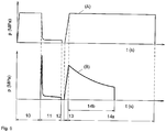
- Fig. 5 shows two pressure-time curves of plastic pipe welds.
- Curve A represents a conventional butt welding method according to DVS (German Association for Welding) after planing.
- the matching 10 can be seen, through which the protruding and already planed, but not planed, pipe ends 8 to a desired temperature brought heating mirror 6 are pressed.
- the adjustment process 10 requires a certain An Eisenbuch.
- the material-dependent An Eisenbuch is generated by the pressing against each other of the pipe ends 8 to the heating mirror 6 and maintained constant until a desired value is reached by a optical control of the dimension of the bead exists.
- the next phase is the heating process 11, in which the pressure is reduced to almost zero. This process gives the joining zone the heat necessary for welding.
- the duration to produce the required melt layer thickness can be determined from a table or empirical values.
- the conversion takes place 12 that is, the tubes 1 are moved apart to remove the heating mirror 6 and then immediately drive the tubes 1 in the welding position.
- the pipe ends 8 are moved together until the desired joining pressure is reached. This is intended to bring about a melt flow in the joining zone during the joining phase 13.
- the subsequent cooling phase 14a the pressure is maintained, the cooling time depends on the width of the joining zone, the achieved melting temperature, the present in the weld melt volume, the thermal properties of the plastic.
- the cooling process is completed when the melt has solidified in the joining zone and the plastic has reached sufficient strength.
- Curve B shows the time-pressure curve of the present invention, in that the pipe projections 6 are planed to an exact dimension and that the temperature of the heating mirror 6 or the heating time 11 of the ambient temperature is thus adapted to the pipe temperature, requires the new, described here Method no match 10 more.
- the ambient temperature is detected by a sensor and, for example, compared with a standard value associated with a heat mirror temperature and calculates the difference.
- the temperature difference of the ambient temperature or pipe temperature to the standard value is subtracted or added accordingly from the SchuLite temperature. This means that at low ambient or pipe temperatures, the heat mirror temperature is added by the corresponding temperature difference to the standard value to compensate for the missing temperature during welding. At pipe temperatures above the standard value, the temperature difference is subtracted accordingly.
- the moderately increased pressure at the beginning of the Anürmphase 11 in curve B is formed by, as already mentioned, Rohrüberstandzugabe of up to 0.5mm compared to the length of the heating stop 7, thereby ensuring that the Pipe overhangs 5 come into contact with the heating mirror 6 and the best possible heat transfer takes place.
- the pressure in the crude supernatant drops as soon as the material in the tube supernatant 5 is so soft that the addition of length is pushed away or melted away by a maximum of 0.5 mm and the clamping points stop at the heating stops 7, then the pressure in the material decreases to almost zero.
- the Anicarmphase 11 of the curve B corresponds to a predetermined period of time to ensure sufficient heat absorption for welding in the joint zones.
- the tube projections would have to be planed precisely to size without any addition and this would entail the risk that the tube ends 8 would not be safe would rest against the heating mirror 6, which would cause a narrow air gap between the heating 6 and pipe end 8 and would hinder good heat transfer.
- the heating mirror 6 is removed after moving apart of the tubes 1, whereupon the tubes 1 are moved together in the joining phase 13.
- the welding process guarantees welding that meets the requirements of the standards, as well as optimized pipe flow due to the minimized bead formation.
Landscapes
- Engineering & Computer Science (AREA)
- Mechanical Engineering (AREA)
- Physics & Mathematics (AREA)
- Thermal Sciences (AREA)
- Life Sciences & Earth Sciences (AREA)
- Forests & Forestry (AREA)
- Health & Medical Sciences (AREA)
- Electromagnetism (AREA)
- Toxicology (AREA)
- Lining Or Joining Of Plastics Or The Like (AREA)
Description
- Die Erfindung betrifft ein Verfahren zum Verschweissen von Kunststoffrohren aus thermoplastischem Kunststoff mittels eines Stumpfschweissverfahrens, wobei die Rohre in koaxialer Lage zueinander mittels Spannstellen gehalten werden, mittels eines Hobels der zwischen die Spannstellen bringbar ist, gehobelt werden und mittels Heizspiegel der anstelle des Hobels montierbar ist, durch Berührung des Heizspiegels aufgeheizt werden, wobei durch die Erwärmung der freien zu verschweissenden Rohrenden ein Aufschmelzbereich erzeugt wird, der beim Verpressen eine Wulst bildet.
Das bekannte Verfahren zur Stumpfschweissung von zwei Kunststoffrohren, läuft bisher im Wesentlichen immer gleich ab, ob es durch manuelle oder automatische Maschinen ausgeführt wird. Die Kunststoffrohre werden in die dafür vorgesehenen Spannstellen eingespannt, wobei die sich gegenüberliegenden Rohrenden aus den Spannstellen herausragen und durch den zwischen den beiden Rohrenden befindenden Hobel und das gegenseitige Zusammenfahren der Spannstellen, in Richtung des rotierenden Hobels, alle Beschädigungen und Verunreinigungen spanend entfernt werden. Zusätzlich wird erreicht, dass die Stirnseiten der Rohrenden rechtwinklig zur Achse des Rohres und parallel zur gegenüberliegenden Stirnseite des andern Rohrendes verlaufen. Anschliessend werden die Rohrenden auseinander gefahren und der Hobel entfernt, daraufhin wird ein Heizspiegel zwischen die Rohre gebracht, worauf die Spannstellen wieder gegeneinander fahren um die Stirnseiten der Rohrenden in Kontakt mit dem Heizspiegel zu bringen. Das Angleichen der Rohrenden findet unter einem vorgegebenen, konstanten Druck, welcher abhängig vom Material, dem Rohrdurchmesser sowie der Wanddicke ist, statt. Der Druck, welcher meist über ein Hydraulikaggregat erzeugt wird, wird so lange auf die beiden Rohrenden bzw. den Heizspiegel ausgeübt, bis am Umfang der Rohrenden Wülste entstehen, die den vorgegebenen Abmessungen entsprechen. In der darauffolgenden Anwärmphase wird der Druck verringert und über eine vorgeschriebene Zeit beibehalten um eine in der Fügezone des Kunststoffrohrs zur Verschweissung benötigtes Temperaturprofil zu erzielen. Danach werden die Spannstellen wieder auseinander geschoben, der Heizspiegel wird entfernt und die Rohrenden anschliessend unter einem vorgegebenen Druck und einer definierte Zeitspanne zusammengepresst, so dass eine erforderliche Durchdringung der Rohrenden erfolgt und eine Verschweissung der Rohrenden garantiert ist. Bei dieser Art zur Herstellung von Schweissverbindungen von Kunststoffrohren sind die Wulste in ihrer Grösse nicht optimiert und fallen gross aus, was einen nachteiligen Einfluss auf die Strömung im Rohr zur Folge hat und zudem lange Prozesszeiten erfordert. Solche Stumpfschweissmaschinen sind aus den SchriftenEP 0 453 903 ,DE 20 2006 003 138 U1 undEP 0802 036 A2 bekannt. Eine ähnliche Technologie mit berührungsloser Heizvorrichtung wird in derEP0535454 gezeigt. - In der
DE 198 27 146 A1 ist ein Verfahren zum Stumpfschweissen von Kunststoffrohren offenbart, wobei der Antrieb der Spannstellen durch einen Elektromotor erfolgt welchem eine Steuerung zugewiesen ist. Ausgehend von der Stellung in der beide Rohrenden mit dem Heizelement in Berührung treten, verfahren die Spannstellen nach einer vorgegebenen, der Steuerung hinterlegten Zeit-Weg-Kurve, welcher zum Angleichen ein erforderlicher Weg zugeordnet ist und während der Anwärmphase im wesentlichen angehalten wird. Nach dem Entfernen der Heizelemente, ausgehend von der Stellung in der zu Beginn des Fügevorgangs beide Rohrenden miteinander in Berührung kommen, legen nach einer zweiten vorbestimmten Zeit-Weg-Kurve die Spannstellen einen bestimmten zum Fügen erforderlichen Weg zurück und werden während der Abkühlphase im Wesentlichen angehalten.
Nachteilig an einer solchen Lösung ist, dass das Verfahren eine komplexe Steuerung benötigt in der für jeden Durchmesser und jedes Material eine dementsprechende Zeit-Weg-Kurve hinterlegt ist. Zudem benötigt die Vorrichtung Fühler bzw. Sensoren zur Bestimmung der Rohrendenposition die während einer Schweissung zweimal ermittelt werden muss. - Es ist Aufgabe der Erfindung ein Verfahren vorzuschlagen, dass eine Rohrendenverschweissung mit einer minimalen Wulstbildung, unter Einhaltung der Sicherheitsbedingungen ermöglicht und den Energie- und Zeitaufwand minimiert und zudem mit einer kostengünstigen und einfachen Steuerung auskommt.
- Diese Aufgabe wird erfindungsgemäss dadurch gelöst, dass der Überstand der Rohre auf ein definiertes Mass gehobelt wird, das heisst, dass die Rohüberstände bei jeder Schweissung auf die selbe Länge vorbereitet werden, was durch mechanische Anschläge, die als Wegbegrenzer dienen, erreicht wird oder durch ein eingebautes und mit der Steuerung verbundenes Wegmesssystem, welches ermöglicht die gewünschte Position exakt anzufahren. Dadurch, dass auf ein definiertes Mass gehobelt wird und die Temperatur des Heizspiegels bzw. die Anwärmzeit mit der Rohrtemperatur welche der Umgebungstemperatur entspricht, abgeglichen wird, ist eine separate Angleichphase die über eine, getrennt von der Anwärmphase, definierte Zeitdauer läuft nicht mehr notwendig. Bisher wurde die Angleichphase, in der während einer vorgegebenen Zeitdauer ein definierter Druck auf die Rohrüberstände ausgeübt wurde, genutzt um eine gewünschte den Anforderungen entsprechende Wulst zu erzielen. Durch die Dimension der Wulst kann auf die Temperatur in der Fügezone geschlossen werden und gewährt somit eine gute Schweissung, allerdings entstehen so grosse Wülste, die die Strömung in den Rohren beeinträchtigen, was durch das neue, hier beschriebene Verfahren vermindert werden kann. Da nun aber ein Berühren der Rohrüberstände mit dem Heizspiegel Vorraussetzung für eine gute Wärmeübertragung ist, weist der Rohrüberstand eine Längenzugabe von bis zu 0.5mm im Vergleich zum Heizanschlag auf, dadurch ist ein minimales Angleichen gegeben, welches in die Phase des Anwärmens integriert wird, da es durch die Temperaturanpassung des Heizspiegels bzw. der Anpassung der Dauer der Anwärmphase an die Rohr- bzw. Umgebungstemperatur keine separate Angleichphase mehr benötigt. Somit hat das Angleichen im neuen, hier beschriebenen Verfahren nicht mehr dieselbe Aufgabe wie im herkömmlichen DVS-Verfahren.
- Die Heizspiegeltemperatur wird im neuen, hier beschriebenen Verfahren an die Rohrtemperatur welche der Umgebungstemperatur entspricht angepasst. Die Umgebungstemperatur wird beispielsweise mit Hilfe eines Sensors ermittelt und wird in der Steuerung mit einem Standardwert, dem eine Heizspiegeltemperatur zugeordnet ist verglichen. Die Differenz zwischen des Standardwerts und des gemessenen Werts wird zur Heizspiegeltemperatur addiert oder von der Heizspiegeltemperatur des Standardwertes subtrahiert. Bei einer tiefen Umgebungstemperatur benötigt es eine entsprechend höhere Heizspiegeltemperatur und umgekehrt.
Eine andere Möglichkeit den Schweissvorgang an die Umgebungstemperatur anzupassen besteht darin, dass die Zeit der Anwärmphase entsprechend verlängert oder verkürzt wird. so dass bei einer tiefen Umgebungstemperatur bzw. Rohrtemperatur die Anwärmphase hinreichend verlängert wird. Anstelle der Ermittlung der Umgebungstemperatur ist es auch denkbar die Rohrtemperatur direkt am Rohr zu messen.
In der Fügephase besteht die Möglichkeit den Fügeweg zu begrenzen, mittels eines mechanischen Anschlags oder eines Wegmesssystems, natürlich besteht auch im neuen, hier beschriebenen Verfahren die Alternative das Fügen druckgesteuert durchzuführen. Das neue, hier beschriebene Verfahren zeichnet sich durch die Verkürzung der Schweisszeit, einen geringen Energieaufwand sowie die Erzielung einer möglichst kleinen Wulst aus. Wobei das neue, hier beschriebene Verfahren so einfach wie möglich durchführbar ist, das heisst das neue, hier beschriebene Verfahren ist ohne jegliche Drucksensoren und Wegmesssysteme durchführbar, allerdings ist eine Erweiterung mit solchen Applikationen durchaus denk- und machbar. - Im Folgenden wird die Erfindung anhand von Zeichnungen eines Ausführungsbeispiels dargestellt. Es zeigen
- Fig. 1
- eine schematische Ansicht einer Vorrichtung zum Verscheissen von Kunststoffrohren nach dem neuen, hier beschriebenen Verfahren vor dem Überhobeln,
- Fig. 2
- eine schematische Ansicht einer Vorrichtung zum Verschweissen von Kunststoffrohren nach dem neuen, hier beschriebenen Verfahren während dem Überhobeln,
- Fig. 3
- eine schematische Ansicht einer Vorrichtung zum Verschweissen von Kunststoffrohren nach dem neuen, hier beschriebenen Verfahren vor dem Anwärmen,
- Fig. 4
- eine schematische Ansicht einer Vorrichtung zum Verscheissen von Kunststoffrohren nach dem neuen, hier beschriebenen Verfahren während dem Anwärmen,
- Fig. 5
- zwei Zeit-Druck-Diagramme in der Fügezone während des kompletten Schweissprozesses.
-
Fig. 1 zeigt die in den Spannstellen 2 eingespannten Rohre 1 vor dem Überhobeln. Am Hobel 3 befinden sich fest montierte Hobelanschläge 4, wodurch sich die Längen der Rohrüberstände 5 genau auf Mass abhobeln lassen, zudem ist garantiert, dass bei jeder Schweissung derselbe Wulst entsteht. InFig. 2 sind die Spannstellen 2 gegen den Hobel 3 gefahren, bis sie an den Hobelanschlägen 4 anstehen, wodurch die genaue Rohrüberstandslänge definiert ist. In einem weiteren Schritt werden die Spannstellen 2 mit den eingespannten Rohren 1 wieder auseinander gefahren um an die Stelle des Hobels 3 den Heizspiegel 6 zu platzieren, wie inFig. 3 dargestellt. Der Heizspiegel 6 weist Heizanschläge 7 auf wodurch ein kontrolliertes, wenn nötiges Angleichen durchführbar ist. Die Heizanschläge 7 sind im Vergleich mit den Hobelanschlägen 4 so ausgebildet, dass sie um bis zu 0,5mm kürzer sind, um zu gewährleisten, dass der Rohrüberstand 5 mit dem Heizspiegel 6 beidseitig in Kontakt kommt.Fig. 4 zeigt, dass die Rohrüberstände 5 geringfügig länger sind als die Heizanschläge 7, wodurch das Zusammenfahren der Spannstellen 2 gegen den Heizspiegel 6 einen Druck im Rohüberstand 5 verursacht, bis sich die Länge des Rohrüberstanders 5 durch die Erwärmung auf die Länge der Heizanschläge 7 reduziert hat bzw. weggeschmolzen ist und die Spannstellen 2 an den Heizanschlägen 7 anstehen. -
Fig. 5 zeigt zwei Druck-Zeit-Kurven von Kunststoffrohr-Verschweissungen. Kurve A stellt ein herkömmliches Stumpfschweissverbindungsverfahren nach DVS (Deutscher Verband für Schweissen) nach dem Hobeln dar. Als erste Phase ist das Angleichen 10 ersichtlich, durch welches die überstehenden und bereits gehobelten, jedoch nicht auf Mass gehobelten, Rohrenden 8 an den auf eine gewünschte Temperatur gebrachten Heizspiegel 6 gedrückt werden. Der Angleichvorgang 10 bedingt einen gewissen Angleichdruck. Der materialabhängige Angleichdruck wird durch das Gegeneinanderpressen der Rohrenden 8 an den Heizspiegel 6 erzeugt und konstant beibehalten bis ein gewünschter Wert erreicht ist, der durch eine optische Kontrolle der Abmessung der Wulst besteht. Als nächste Phase erfolgt der Anwärmvorgang 11, bei dem der Druck auf nahezu null reduziert wird. Dieser Vorgang gewährt der Fügezone die zur Schweissung notwendige Wärme. Die Dauer um die erforderliche Schmelzschichtdicke zu erzeugen, kann aus einer Tabelle bzw. Erfahrungswerten ermittelt werden.
Als weiterer Schritt erfolgt die Umstellung 12, das heisst die Rohre 1 werden auseinander gefahren um den Heizspiegel 6 zu entfernen und um danach sofort die Rohre 1 in die Schweissposition zu fahren. Die Rohrenden 8 werden zusammengefahren bis der gewünschte, den Anforderungen entsprechende Fügedruck erreicht ist. Dadurch soll ein Schmelzfluss in der Fügezone während der Fügephase 13 bewirkt werden. In der anschliessenden Abkühlphase 14a wird der Druck aufrecht gehalten, die Abkühlzeit hängt von der Breite der Fügezone, der erreichten Schmelztemperatur, dem in der Schweissnaht vorliegenden Schmelzvolumen, den thermischen Eigenschaften des Kunststoffs ab. Der Abkühlvorgang ist beendet, wenn die Schmelze in der Fügezone erstarrt ist und der Kunststoff genügend Festigkeit erreicht hat. - Kurve B zeigt den Zeit-Druck-Verlauf der vorliegenden Erfindung, dadurch dass die Rohrüberstände 6 auf ein exaktes Mass gehobelt sind und dass die Temperatur des Heizspiegels 6 bzw. die Anwärmzeit 11 der Umgebungstemperatur somit der Rohrtemperatur angepasst wird, benötigt das neue, hier beschriebene Verfahren kein Angleichen 10 mehr. Die Umgebungstemperatur wird durch einen Sensor erfasst und beispielsweise mit einem Standardwert, dem eine Heizspiegeltemperatur zugeordnet ist verglichen und die Differenz berechnet. Die Temperaturdifferenz der Umgebungstemperatur bzw. Rohrtemperatur zum Standardwert wird von der Heizspiegeltemperatur entsprechend subtrahiert oder addiert. Das heisst, bei tiefen Umgebungs- bzw. Rohrtemperaturen wird die Heizspiegeltemperatur um die entsprechende Temperaturdifferenz zum Standardwert addiert um die fehlende Temperatur bei der Schweissung zu kompensieren. Bei Rohrtemperaturen oberhalb des Standardwertes wird die Temperaturdifferenz dementsprechend subtrahiert. Durch ein solches Vorgehen kann die Phase des Angleichens 10 eingespart werden. Der kurzeitig erhöhte Druck am Anfang der Anwärmphase 11 in Kurve B entsteht durch die, wie bereits erwähnte, Rohrüberstandzugabe von bis zu 0.5mm im Vergleich zur Länge des Heizanschlags 7, dadurch ist gesichert, dass die Rohrüberstände 5 mit dem Heizspiegel 6 in Berührung kommen und eine bestmögliche Wärmeübertragung stattfindet. Der Druck im Rohüberstand sinkt sobald das Material im Rohrüberstand 5 so weich ist, dass die Längenzugabe von maximal 0.5mm weggedrückt bzw. weggeschmolzen ist und die Spannstellen an den Heizanschlägen 7 anstehen, dann verringet sich der Druck im Material auf nahezu null. Die Anwärmphase 11 der Kurve B entspricht einer vorgegebenen Zeitspanne um eine ausreichende Wärmeaufnahme zur Verschweissung in den Fügezonen zu gewährleistet. Theoretisch wäre es denkbar, während der Anwärmphase 11 des neuen hier beschriebenen Verfahrens den hohen Druck zu Beginn zu vermeiden, allerdings müssten die Rohrüberstände genau auf Mass ohne jegliche Zugabe gehobelt werden und das würde das Risiko mit sich bringen, dass die Rohrenden 8 nicht mit Sicherheit am Heizspiegel 6 anliegen würden, was einen schmalen Luftspalt zwischen Heizspiegel 6 und Rohrende 8 verursachen und eine gute Wärmeübertragung behindern würde. In der Phase 12 erfolgt die Umstellung, der Heizspiegel 6 wird nach dem Auseinanderfahren der Rohre 1 entfernt, woraufhin die Rohre 1 in der Fügephase 13 zusammengefahren werden. Dieser Vorgang kann sowohl weg- wie auch druckgesteuert ablaufen, zudem ist auch eine Kombination einer Weg-Drucksteuerung während der Fügephase 13 denkbar.
Durch die Materialeinsparung im neuen, hier beschriebenen Verfahren B wodurch eine unnötig grosse Wulstbildung bei der Verschweissung vermieden werden kann, ist die Abkühlphase 14b entsprechend kürzer. InFig. 5 ist ein weggesteuertes Fügen 13 dargestellt, ersichtlich durch den Druckabfall nach dem Fügen, da das Material in der Fügezone beim Abkühlen 14b schwindet. Denkbar ist auch ein druckgesteuertes Fügen, was aus dem Stand der Technik bekannt ist und was während der Abkühlphase den Druck konstant beibehalten würde. Beide Varianten der Abkühlung werden während einer der Steuerung hinterlegten vorgegebenen Zeitspanne durchgeführt. Zur Überwachung des Abkühlvorgangs ist auch eine Messung der Rohrtemperatur in der Fügezone während der Abkühlphase vorstellbar, wodurch festgestellt wird, wann die Temperatur ausreichend gesunken ist um die Rohre 1 aus den Spannstellen 2 zu lösen. Das Schweissverfahren gewährt neben geringem Zeitbedarf und Energieeinsparung eine Schweissung, die den Anforderungen der Normen entspricht, sowie eine optimierte Rohrströmung aufgrund der minimierten Wulstbildung.
Claims (5)
- Verfahren zum Verschweissen von Kunststoffrohren (1) aus thermoplastischem Kunststoff mittels eines Stumpfschweissverfahrens, wobei die Rohre (1) in koaxialer Lage zueinander mittels Spannstellen (2) gehalten werden, mittels eines Hobels (3) der zwischen die Spannstellen (2) bringbar ist, gehobelt werden und mittels eines Heizspiegels (6), der anstelle des Hobels (3) montierbar ist, durch Berührung des Heizspiegels aufgeheizt werden, wobei durch die Erwärmung der freien zu verschweissenden Rohrenden (8) ein Aufschmelzbereich erzeugt wird, der beim Verpressen eine Wulst bildet, wobei der Rohrüberstand (5) der jeweiligen Rohre (1) auf ein definiertes Mass gehobelt wird, und ein Angleichen während einer Anwärmphase (11) erfolgt.
- Verfahren nach Anspruch 1, dadurch gekennzeichnet, dass die Fügephase (13) weggesteuert ist.
- Verfahren nach einem der Ansprüche 1 oder 2, dadurch gekennzeichnet dass die Fügephase (13) druckgesteuert ist.
- Verfahren nach Anspruch 1, dadurch gekennzeichnet, dass die Heiztemperatur des Heizspiegels sich entsprechend der Umgebungstemperatur anpasst, das heisst, bei tiefer Umgebungstemperatur eine entsprechend höhere Heizspiegeltemperatur und umgekehrt eingestellt wird.
- Verfahren nach einem der Ansprüche 1 oder 4, dadurch gekennzeichnet, dass die Dauer der Anwärmphase abhängig von der Umgebungstemperatur ist.
Priority Applications (8)
| Application Number | Priority Date | Filing Date | Title |
|---|---|---|---|
| EP10166105.6A EP2397311B1 (de) | 2010-06-16 | 2010-06-16 | Verfahren und Vorrichtung zum Stumpfschweissen von Rohren aus thermoplastischem Kunststoff |
| TW100117946A TWI561366B (en) | 2010-06-16 | 2011-05-23 | Method and device for the butt-welding of pipes made of thermoplastic material |
| SG2012073979A SG185360A1 (en) | 2010-06-16 | 2011-06-01 | Method and device for the butt-welding of pipes made of thermoplastic material |
| CN2011800294739A CN103068557A (zh) | 2010-06-16 | 2011-06-01 | 用于对由热塑性塑料制成的管进行对接焊的方法和装置 |
| JP2013514628A JP2013528516A (ja) | 2010-06-16 | 2011-06-01 | 熱可塑性のプラスチックからなる管をバット融着する方法及び装置 |
| PCT/EP2011/059097 WO2011157563A1 (de) | 2010-06-16 | 2011-06-01 | Verfahren und vorrichtung zum stumpfschweissen von rohren aus thermoplastischem kunststoff |
| KR1020137001079A KR20130023343A (ko) | 2010-06-16 | 2011-06-01 | 열가소성 재료로 제조된 파이프들을 맞대기 용접하는 방법 및 장치 |
| US13/704,090 US9358743B2 (en) | 2010-06-16 | 2011-06-01 | Method and device for the butt-welding of pipes made of thermoplastic material |
Applications Claiming Priority (1)
| Application Number | Priority Date | Filing Date | Title |
|---|---|---|---|
| EP10166105.6A EP2397311B1 (de) | 2010-06-16 | 2010-06-16 | Verfahren und Vorrichtung zum Stumpfschweissen von Rohren aus thermoplastischem Kunststoff |
Publications (2)
| Publication Number | Publication Date |
|---|---|
| EP2397311A1 EP2397311A1 (de) | 2011-12-21 |
| EP2397311B1 true EP2397311B1 (de) | 2018-09-26 |
Family
ID=43034365
Family Applications (1)
| Application Number | Title | Priority Date | Filing Date |
|---|---|---|---|
| EP10166105.6A Active EP2397311B1 (de) | 2010-06-16 | 2010-06-16 | Verfahren und Vorrichtung zum Stumpfschweissen von Rohren aus thermoplastischem Kunststoff |
Country Status (8)
| Country | Link |
|---|---|
| US (1) | US9358743B2 (de) |
| EP (1) | EP2397311B1 (de) |
| JP (1) | JP2013528516A (de) |
| KR (1) | KR20130023343A (de) |
| CN (1) | CN103068557A (de) |
| SG (1) | SG185360A1 (de) |
| TW (1) | TWI561366B (de) |
| WO (1) | WO2011157563A1 (de) |
Cited By (1)
| Publication number | Priority date | Publication date | Assignee | Title |
|---|---|---|---|---|
| EP4501598A1 (de) * | 2023-08-02 | 2025-02-05 | Georg Fischer Rohrleitungssysteme AG | Variabler schweissabstand |
Families Citing this family (8)
| Publication number | Priority date | Publication date | Assignee | Title |
|---|---|---|---|---|
| KR101406076B1 (ko) * | 2013-01-08 | 2014-06-13 | 한전원자력연료 주식회사 | 핵연료봉의 봉단마개 자동 용접장치 |
| CN104607816B (zh) * | 2015-01-16 | 2017-01-25 | 苏州凯尔博精密机械有限公司 | 一种多穴分油管焊接机 |
| EP3257656B1 (de) * | 2016-06-16 | 2018-12-05 | Georg Fischer Rohrleitungssysteme AG | Rohrendenerkennung |
| EP3839319B1 (de) * | 2018-05-29 | 2023-07-05 | Georg Fischer Rohrleitungssysteme AG | Elektroschweissband, verwendung und verfahren |
| EP3804965B1 (de) * | 2019-10-10 | 2025-09-17 | Hürner Schweisstechnik GmbH | Verfahren und vorrichtung zur herstellung einer stumpfschweissverbindung |
| EP4194184B1 (de) * | 2021-12-07 | 2025-07-16 | Georg Fischer Rohrleitungssysteme AG | Schweissungsbeurteilung während schweissprozess |
| CN116872512A (zh) * | 2023-08-11 | 2023-10-13 | 宁波宇华实业股份有限公司 | 一种pe管道热熔焊接装置及焊接工艺 |
| CN117565413B (zh) * | 2024-01-16 | 2024-03-19 | 四川聚诚达环保科技有限公司 | 一种玄武岩增强塑料化粪池热熔连接装置及方法 |
Citations (5)
| Publication number | Priority date | Publication date | Assignee | Title |
|---|---|---|---|---|
| EP0535454A2 (de) * | 1991-10-04 | 1993-04-07 | Georg Fischer Rohrleitungssysteme AG | Einrichtung zum Verschweissen von Kunststoffteilen |
| US5620625A (en) * | 1992-06-01 | 1997-04-15 | Gaz De France (Service National) | Method of butt-welding two plastic parts with an identifying code, using an automatically controlled electro-welding machine |
| EP0802036A2 (de) * | 1996-04-18 | 1997-10-22 | Rothenberger Werkzeuge AG | Vorrichtung zum Stumpfschweissen von thermoplastischen Kunststoffrohren |
| EP1295697A1 (de) * | 2001-09-24 | 2003-03-26 | Georg Fischer Rohrverbindungstechnik GmbH | Einrichtung zum stirnseitigen Verschweissen von rohrförmigen Teilen aus thermoplastischem Material |
| DE202006003138U1 (de) * | 2006-02-24 | 2006-11-09 | Simona Ag | Schweißanlage zum Verschweißen von Kunststoffrohren |
Family Cites Families (13)
| Publication number | Priority date | Publication date | Assignee | Title |
|---|---|---|---|---|
| JPS5920881Y2 (ja) * | 1979-10-03 | 1984-06-18 | 大阪瓦斯株式会社 | 融着機 |
| JPH066347B2 (ja) * | 1986-05-14 | 1994-01-26 | ナシヨナルタイヤ株式会社 | 車両タイヤ用チユ−ブの製造方法 |
| GB8615517D0 (en) * | 1986-06-25 | 1986-07-30 | Fusion Equipment Ltd | Butt-welding of pipes |
| US5013376A (en) * | 1989-10-02 | 1991-05-07 | Mcelroy Manufacturing, Inc. | Programmable computer controlled pipe fusion device |
| DE4013471A1 (de) * | 1990-04-27 | 1991-10-31 | Fischer Ag Georg | Einrichtung zum stirnseitigen verschweissen von kunststoffteilen |
| US5241157A (en) * | 1990-04-27 | 1993-08-31 | Georg Fischer Ag | Arrangement for butt-welding plastic material components |
| US5325604A (en) * | 1992-12-17 | 1994-07-05 | The University Of Tennessee Research Corporation | Automatic control system for wood drying kiln |
| US5484506A (en) * | 1994-05-16 | 1996-01-16 | Sani-Tech Incorporated | Smooth bore welding of thermoplastic tubing |
| CN2277878Y (zh) * | 1996-12-25 | 1998-04-08 | 高秋源 | 塑料直管热熔对接机 |
| FR2762540B1 (fr) * | 1997-04-23 | 1999-06-11 | Gaz De France | Perfectionnement a un procede de soudage bout a bout |
| DE19827146A1 (de) | 1998-06-18 | 1999-12-23 | Ulrike Richter | Verfahren und Vorrichtung zum Stumpfschweißen von Rohren aus thermoplastischem Kunststoff |
| US6994766B2 (en) * | 2002-03-08 | 2006-02-07 | Pe Fusion, Llc | Beveled cutter |
| US7328734B2 (en) * | 2003-09-29 | 2008-02-12 | Royal Group, Inc. | Portable thermo-plastic welding machine and method |
-
2010
- 2010-06-16 EP EP10166105.6A patent/EP2397311B1/de active Active
-
2011
- 2011-05-23 TW TW100117946A patent/TWI561366B/zh not_active IP Right Cessation
- 2011-06-01 JP JP2013514628A patent/JP2013528516A/ja active Pending
- 2011-06-01 CN CN2011800294739A patent/CN103068557A/zh active Pending
- 2011-06-01 KR KR1020137001079A patent/KR20130023343A/ko not_active Withdrawn
- 2011-06-01 US US13/704,090 patent/US9358743B2/en active Active
- 2011-06-01 SG SG2012073979A patent/SG185360A1/en unknown
- 2011-06-01 WO PCT/EP2011/059097 patent/WO2011157563A1/de not_active Ceased
Patent Citations (5)
| Publication number | Priority date | Publication date | Assignee | Title |
|---|---|---|---|---|
| EP0535454A2 (de) * | 1991-10-04 | 1993-04-07 | Georg Fischer Rohrleitungssysteme AG | Einrichtung zum Verschweissen von Kunststoffteilen |
| US5620625A (en) * | 1992-06-01 | 1997-04-15 | Gaz De France (Service National) | Method of butt-welding two plastic parts with an identifying code, using an automatically controlled electro-welding machine |
| EP0802036A2 (de) * | 1996-04-18 | 1997-10-22 | Rothenberger Werkzeuge AG | Vorrichtung zum Stumpfschweissen von thermoplastischen Kunststoffrohren |
| EP1295697A1 (de) * | 2001-09-24 | 2003-03-26 | Georg Fischer Rohrverbindungstechnik GmbH | Einrichtung zum stirnseitigen Verschweissen von rohrförmigen Teilen aus thermoplastischem Material |
| DE202006003138U1 (de) * | 2006-02-24 | 2006-11-09 | Simona Ag | Schweißanlage zum Verschweißen von Kunststoffrohren |
Cited By (1)
| Publication number | Priority date | Publication date | Assignee | Title |
|---|---|---|---|---|
| EP4501598A1 (de) * | 2023-08-02 | 2025-02-05 | Georg Fischer Rohrleitungssysteme AG | Variabler schweissabstand |
Also Published As
| Publication number | Publication date |
|---|---|
| KR20130023343A (ko) | 2013-03-07 |
| US20130126088A1 (en) | 2013-05-23 |
| SG185360A1 (en) | 2013-01-30 |
| CN103068557A (zh) | 2013-04-24 |
| EP2397311A1 (de) | 2011-12-21 |
| TWI561366B (en) | 2016-12-11 |
| WO2011157563A1 (de) | 2011-12-22 |
| US9358743B2 (en) | 2016-06-07 |
| JP2013528516A (ja) | 2013-07-11 |
| TW201208867A (en) | 2012-03-01 |
Similar Documents
| Publication | Publication Date | Title |
|---|---|---|
| EP2397311A1 (de) | Verfahren und Vorrichtung zum Stumpfschweissen von Rohren aus thermoplastischem Kunststoff | |
| DE4206584C2 (de) | Vorrichtung und Verfahren zum Verbinden zweier Bauteile mittels Ultraschall | |
| DE2127663C3 (de) | ||
| EP0355579B1 (de) | Verfahren und Einrichtung zum Verschweissen von rohrförmigen Teilen aus Kunststoff | |
| EP0020915B1 (de) | Verfahren zum nahtlosen Verbinden von thermoplastischen Kunststoffhohlprofilen und Vorrichtung zur Durchführung des Verfahrens | |
| DE2455603C3 (de) | Verfahren zum Verschweißen von Oberflächen von Gegenständen aus Polyolefinen mit unterschiedlichem Schmelzindex sowie Vorrichtung zu seiner Durchführung | |
| DE102018130769B3 (de) | Vorrichtung und Verfahren zum Stumpfschweißen von Werkstücken | |
| DE10360471B4 (de) | Verfahren und Vorrichtung zum Aufbringen einer Verstärkung auf ein Kunststoffrohr durch ein Wickelschweißverfahren | |
| DE2127663B2 (de) | Reibschweissverfahren sowie vorrichtung zu seiner durchfuehrung | |
| EP0899085B1 (de) | Verfahren zum Verschweissen von Kunststoffteilen | |
| WO2012093112A1 (de) | Vorrichtung und verfahren zur herstellung von tubenrohren für verpackungstuben | |
| DE4203626A1 (de) | Schweissmuffe und verfahren zu deren herstellung | |
| DE102011001167B4 (de) | Verfahren zum Betreiben einer Schweißvorrichtung, insbesondere eines wärmeimpulsgesteuerten und/oder dauerbeheizten Folienschweiß- und/oder Heißsiegelgerätes mit vorwählbarer elektronischer, prozessorgesteuerter Anpressdruck- und Temperaturregelung und Vorrichtung hierzu | |
| WO1990000112A2 (de) | Einrichtung zum verschweissen von rohrförmigen teilen aus kunststoff | |
| EP1692080A1 (de) | VERFAHREN UND VORRICHTUNG ZUR HERSTELLUNG EINES GLASKöRPERS | |
| EP3687762B1 (de) | Verfahren zur herstellung von kunststoffhohlkörpern | |
| EP3138652B1 (de) | Elektrisches schweissverfahren | |
| EP1382433A1 (de) | Verfahren zum Fügen von Kunststoffbauteilen mittels Laserstrahlung | |
| EP1136234B1 (de) | Verfahren und Vorrichtung zum Verschweissen von Kunststoffprofilstäben | |
| DE19813625C1 (de) | Verfahren und Fahrzeug zum Verbinden von mit überlappenden Rändern verlegten Dachbahnen | |
| EP3238871B1 (de) | Verfahren zur herstellung eines rohres aus metall durch laserschweissen | |
| EP2465635B1 (de) | Verfahren und Vorrichtung zum Erzeugen einer Laserschweißnaht | |
| DE102010012358B4 (de) | Verfahren und Vorrichtung zum simultanen Herstellen mehrerer Schweißverbindungen | |
| DE19827146A1 (de) | Verfahren und Vorrichtung zum Stumpfschweißen von Rohren aus thermoplastischem Kunststoff | |
| AT522497B1 (de) | Verfahren zum Herstellen eines Rohres, sowie Vorrichtung zum Durchführen des Verfahrens |
Legal Events
| Date | Code | Title | Description |
|---|---|---|---|
| AK | Designated contracting states |
Kind code of ref document: A1 Designated state(s): AL AT BE BG CH CY CZ DE DK EE ES FI FR GB GR HR HU IE IS IT LI LT LU LV MC MK MT NL NO PL PT RO SE SI SK SM TR |
|
| AX | Request for extension of the european patent |
Extension state: BA ME RS |
|
| PUAI | Public reference made under article 153(3) epc to a published international application that has entered the european phase |
Free format text: ORIGINAL CODE: 0009012 |
|
| 17P | Request for examination filed |
Effective date: 20120529 |
|
| 17Q | First examination report despatched |
Effective date: 20130708 |
|
| STAA | Information on the status of an ep patent application or granted ep patent |
Free format text: STATUS: EXAMINATION IS IN PROGRESS |
|
| GRAP | Despatch of communication of intention to grant a patent |
Free format text: ORIGINAL CODE: EPIDOSNIGR1 |
|
| STAA | Information on the status of an ep patent application or granted ep patent |
Free format text: STATUS: GRANT OF PATENT IS INTENDED |
|
| INTG | Intention to grant announced |
Effective date: 20180507 |
|
| GRAS | Grant fee paid |
Free format text: ORIGINAL CODE: EPIDOSNIGR3 |
|
| GRAA | (expected) grant |
Free format text: ORIGINAL CODE: 0009210 |
|
| STAA | Information on the status of an ep patent application or granted ep patent |
Free format text: STATUS: THE PATENT HAS BEEN GRANTED |
|
| AK | Designated contracting states |
Kind code of ref document: B1 Designated state(s): AL AT BE BG CH CY CZ DE DK EE ES FI FR GB GR HR HU IE IS IT LI LT LU LV MC MK MT NL NO PL PT RO SE SI SK SM TR |
|
| REG | Reference to a national code |
Ref country code: GB Ref legal event code: FG4D Free format text: NOT ENGLISH |
|
| REG | Reference to a national code |
Ref country code: CH Ref legal event code: EP |
|
| REG | Reference to a national code |
Ref country code: AT Ref legal event code: REF Ref document number: 1045491 Country of ref document: AT Kind code of ref document: T Effective date: 20181015 |
|
| REG | Reference to a national code |
Ref country code: IE Ref legal event code: FG4D Free format text: LANGUAGE OF EP DOCUMENT: GERMAN |
|
| REG | Reference to a national code |
Ref country code: DE Ref legal event code: R096 Ref document number: 502010015399 Country of ref document: DE |
|
| REG | Reference to a national code |
Ref country code: NL Ref legal event code: MP Effective date: 20180926 |
|
| PG25 | Lapsed in a contracting state [announced via postgrant information from national office to epo] |
Ref country code: LT Free format text: LAPSE BECAUSE OF FAILURE TO SUBMIT A TRANSLATION OF THE DESCRIPTION OR TO PAY THE FEE WITHIN THE PRESCRIBED TIME-LIMIT Effective date: 20180926 Ref country code: NO Free format text: LAPSE BECAUSE OF FAILURE TO SUBMIT A TRANSLATION OF THE DESCRIPTION OR TO PAY THE FEE WITHIN THE PRESCRIBED TIME-LIMIT Effective date: 20181226 Ref country code: FI Free format text: LAPSE BECAUSE OF FAILURE TO SUBMIT A TRANSLATION OF THE DESCRIPTION OR TO PAY THE FEE WITHIN THE PRESCRIBED TIME-LIMIT Effective date: 20180926 Ref country code: GR Free format text: LAPSE BECAUSE OF FAILURE TO SUBMIT A TRANSLATION OF THE DESCRIPTION OR TO PAY THE FEE WITHIN THE PRESCRIBED TIME-LIMIT Effective date: 20181227 Ref country code: SE Free format text: LAPSE BECAUSE OF FAILURE TO SUBMIT A TRANSLATION OF THE DESCRIPTION OR TO PAY THE FEE WITHIN THE PRESCRIBED TIME-LIMIT Effective date: 20180926 Ref country code: BG Free format text: LAPSE BECAUSE OF FAILURE TO SUBMIT A TRANSLATION OF THE DESCRIPTION OR TO PAY THE FEE WITHIN THE PRESCRIBED TIME-LIMIT Effective date: 20181226 |
|
| REG | Reference to a national code |
Ref country code: LT Ref legal event code: MG4D |
|
| PG25 | Lapsed in a contracting state [announced via postgrant information from national office to epo] |
Ref country code: LV Free format text: LAPSE BECAUSE OF FAILURE TO SUBMIT A TRANSLATION OF THE DESCRIPTION OR TO PAY THE FEE WITHIN THE PRESCRIBED TIME-LIMIT Effective date: 20180926 Ref country code: AL Free format text: LAPSE BECAUSE OF FAILURE TO SUBMIT A TRANSLATION OF THE DESCRIPTION OR TO PAY THE FEE WITHIN THE PRESCRIBED TIME-LIMIT Effective date: 20180926 Ref country code: HR Free format text: LAPSE BECAUSE OF FAILURE TO SUBMIT A TRANSLATION OF THE DESCRIPTION OR TO PAY THE FEE WITHIN THE PRESCRIBED TIME-LIMIT Effective date: 20180926 |
|
| PG25 | Lapsed in a contracting state [announced via postgrant information from national office to epo] |
Ref country code: IT Free format text: LAPSE BECAUSE OF FAILURE TO SUBMIT A TRANSLATION OF THE DESCRIPTION OR TO PAY THE FEE WITHIN THE PRESCRIBED TIME-LIMIT Effective date: 20180926 Ref country code: RO Free format text: LAPSE BECAUSE OF FAILURE TO SUBMIT A TRANSLATION OF THE DESCRIPTION OR TO PAY THE FEE WITHIN THE PRESCRIBED TIME-LIMIT Effective date: 20180926 Ref country code: ES Free format text: LAPSE BECAUSE OF FAILURE TO SUBMIT A TRANSLATION OF THE DESCRIPTION OR TO PAY THE FEE WITHIN THE PRESCRIBED TIME-LIMIT Effective date: 20180926 Ref country code: NL Free format text: LAPSE BECAUSE OF FAILURE TO SUBMIT A TRANSLATION OF THE DESCRIPTION OR TO PAY THE FEE WITHIN THE PRESCRIBED TIME-LIMIT Effective date: 20180926 Ref country code: CZ Free format text: LAPSE BECAUSE OF FAILURE TO SUBMIT A TRANSLATION OF THE DESCRIPTION OR TO PAY THE FEE WITHIN THE PRESCRIBED TIME-LIMIT Effective date: 20180926 Ref country code: EE Free format text: LAPSE BECAUSE OF FAILURE TO SUBMIT A TRANSLATION OF THE DESCRIPTION OR TO PAY THE FEE WITHIN THE PRESCRIBED TIME-LIMIT Effective date: 20180926 Ref country code: PL Free format text: LAPSE BECAUSE OF FAILURE TO SUBMIT A TRANSLATION OF THE DESCRIPTION OR TO PAY THE FEE WITHIN THE PRESCRIBED TIME-LIMIT Effective date: 20180926 Ref country code: IS Free format text: LAPSE BECAUSE OF FAILURE TO SUBMIT A TRANSLATION OF THE DESCRIPTION OR TO PAY THE FEE WITHIN THE PRESCRIBED TIME-LIMIT Effective date: 20190126 |
|
| PG25 | Lapsed in a contracting state [announced via postgrant information from national office to epo] |
Ref country code: SK Free format text: LAPSE BECAUSE OF FAILURE TO SUBMIT A TRANSLATION OF THE DESCRIPTION OR TO PAY THE FEE WITHIN THE PRESCRIBED TIME-LIMIT Effective date: 20180926 Ref country code: PT Free format text: LAPSE BECAUSE OF FAILURE TO SUBMIT A TRANSLATION OF THE DESCRIPTION OR TO PAY THE FEE WITHIN THE PRESCRIBED TIME-LIMIT Effective date: 20190126 Ref country code: SM Free format text: LAPSE BECAUSE OF FAILURE TO SUBMIT A TRANSLATION OF THE DESCRIPTION OR TO PAY THE FEE WITHIN THE PRESCRIBED TIME-LIMIT Effective date: 20180926 |
|
| REG | Reference to a national code |
Ref country code: DE Ref legal event code: R097 Ref document number: 502010015399 Country of ref document: DE |
|
| PG25 | Lapsed in a contracting state [announced via postgrant information from national office to epo] |
Ref country code: DK Free format text: LAPSE BECAUSE OF FAILURE TO SUBMIT A TRANSLATION OF THE DESCRIPTION OR TO PAY THE FEE WITHIN THE PRESCRIBED TIME-LIMIT Effective date: 20180926 |
|
| PLBE | No opposition filed within time limit |
Free format text: ORIGINAL CODE: 0009261 |
|
| STAA | Information on the status of an ep patent application or granted ep patent |
Free format text: STATUS: NO OPPOSITION FILED WITHIN TIME LIMIT |
|
| 26N | No opposition filed |
Effective date: 20190627 |
|
| PG25 | Lapsed in a contracting state [announced via postgrant information from national office to epo] |
Ref country code: SI Free format text: LAPSE BECAUSE OF FAILURE TO SUBMIT A TRANSLATION OF THE DESCRIPTION OR TO PAY THE FEE WITHIN THE PRESCRIBED TIME-LIMIT Effective date: 20180926 |
|
| PG25 | Lapsed in a contracting state [announced via postgrant information from national office to epo] |
Ref country code: MC Free format text: LAPSE BECAUSE OF FAILURE TO SUBMIT A TRANSLATION OF THE DESCRIPTION OR TO PAY THE FEE WITHIN THE PRESCRIBED TIME-LIMIT Effective date: 20180926 |
|
| GBPC | Gb: european patent ceased through non-payment of renewal fee |
Effective date: 20190616 |
|
| REG | Reference to a national code |
Ref country code: BE Ref legal event code: MM Effective date: 20190630 |
|
| PG25 | Lapsed in a contracting state [announced via postgrant information from national office to epo] |
Ref country code: TR Free format text: LAPSE BECAUSE OF FAILURE TO SUBMIT A TRANSLATION OF THE DESCRIPTION OR TO PAY THE FEE WITHIN THE PRESCRIBED TIME-LIMIT Effective date: 20180926 |
|
| PG25 | Lapsed in a contracting state [announced via postgrant information from national office to epo] |
Ref country code: IE Free format text: LAPSE BECAUSE OF NON-PAYMENT OF DUE FEES Effective date: 20190616 Ref country code: GB Free format text: LAPSE BECAUSE OF NON-PAYMENT OF DUE FEES Effective date: 20190616 |
|
| PG25 | Lapsed in a contracting state [announced via postgrant information from national office to epo] |
Ref country code: BE Free format text: LAPSE BECAUSE OF NON-PAYMENT OF DUE FEES Effective date: 20190630 Ref country code: LU Free format text: LAPSE BECAUSE OF NON-PAYMENT OF DUE FEES Effective date: 20190616 |
|
| PG25 | Lapsed in a contracting state [announced via postgrant information from national office to epo] |
Ref country code: FR Free format text: LAPSE BECAUSE OF NON-PAYMENT OF DUE FEES Effective date: 20190630 |
|
| PG25 | Lapsed in a contracting state [announced via postgrant information from national office to epo] |
Ref country code: CY Free format text: LAPSE BECAUSE OF FAILURE TO SUBMIT A TRANSLATION OF THE DESCRIPTION OR TO PAY THE FEE WITHIN THE PRESCRIBED TIME-LIMIT Effective date: 20180926 |
|
| PG25 | Lapsed in a contracting state [announced via postgrant information from national office to epo] |
Ref country code: HU Free format text: LAPSE BECAUSE OF FAILURE TO SUBMIT A TRANSLATION OF THE DESCRIPTION OR TO PAY THE FEE WITHIN THE PRESCRIBED TIME-LIMIT; INVALID AB INITIO Effective date: 20100616 Ref country code: MT Free format text: LAPSE BECAUSE OF FAILURE TO SUBMIT A TRANSLATION OF THE DESCRIPTION OR TO PAY THE FEE WITHIN THE PRESCRIBED TIME-LIMIT Effective date: 20180926 |
|
| PG25 | Lapsed in a contracting state [announced via postgrant information from national office to epo] |
Ref country code: MK Free format text: LAPSE BECAUSE OF FAILURE TO SUBMIT A TRANSLATION OF THE DESCRIPTION OR TO PAY THE FEE WITHIN THE PRESCRIBED TIME-LIMIT Effective date: 20180926 |
|
| P01 | Opt-out of the competence of the unified patent court (upc) registered |
Effective date: 20230529 |
|
| PGFP | Annual fee paid to national office [announced via postgrant information from national office to epo] |
Ref country code: DE Payment date: 20250618 Year of fee payment: 16 |
|
| PGFP | Annual fee paid to national office [announced via postgrant information from national office to epo] |
Ref country code: AT Payment date: 20250620 Year of fee payment: 16 |
|
| PGFP | Annual fee paid to national office [announced via postgrant information from national office to epo] |
Ref country code: CH Payment date: 20250701 Year of fee payment: 16 |