EP2397258A2 - Visseuse - Google Patents
Visseuse Download PDFInfo
- Publication number
- EP2397258A2 EP2397258A2 EP20110164030 EP11164030A EP2397258A2 EP 2397258 A2 EP2397258 A2 EP 2397258A2 EP 20110164030 EP20110164030 EP 20110164030 EP 11164030 A EP11164030 A EP 11164030A EP 2397258 A2 EP2397258 A2 EP 2397258A2
- Authority
- EP
- European Patent Office
- Prior art keywords
- speed
- drive
- torque
- certain
- rotational speed
- Prior art date
- Legal status (The legal status is an assumption and is not a legal conclusion. Google has not performed a legal analysis and makes no representation as to the accuracy of the status listed.)
- Granted
Links
Images


Classifications
-
- B—PERFORMING OPERATIONS; TRANSPORTING
- B25—HAND TOOLS; PORTABLE POWER-DRIVEN TOOLS; MANIPULATORS
- B25B—TOOLS OR BENCH DEVICES NOT OTHERWISE PROVIDED FOR, FOR FASTENING, CONNECTING, DISENGAGING OR HOLDING
- B25B23/00—Details of, or accessories for, spanners, wrenches, screwdrivers
- B25B23/14—Arrangement of torque limiters or torque indicators in wrenches or screwdrivers
-
- B—PERFORMING OPERATIONS; TRANSPORTING
- B25—HAND TOOLS; PORTABLE POWER-DRIVEN TOOLS; MANIPULATORS
- B25B—TOOLS OR BENCH DEVICES NOT OTHERWISE PROVIDED FOR, FOR FASTENING, CONNECTING, DISENGAGING OR HOLDING
- B25B21/00—Portable power-driven screw or nut setting or loosening tools; Attachments for drilling apparatus serving the same purpose
-
- B—PERFORMING OPERATIONS; TRANSPORTING
- B25—HAND TOOLS; PORTABLE POWER-DRIVEN TOOLS; MANIPULATORS
- B25B—TOOLS OR BENCH DEVICES NOT OTHERWISE PROVIDED FOR, FOR FASTENING, CONNECTING, DISENGAGING OR HOLDING
- B25B23/00—Details of, or accessories for, spanners, wrenches, screwdrivers
- B25B23/14—Arrangement of torque limiters or torque indicators in wrenches or screwdrivers
- B25B23/147—Arrangement of torque limiters or torque indicators in wrenches or screwdrivers specially adapted for electrically operated wrenches or screwdrivers
Definitions
- Such a screwdriver is from the EP 1 785 231 A2 known.
- the well-known screwdriver has a control device by means of which the speed of the motor can be regulated and which reduces the speed when a trigger parameter is reached.
- an angular velocity change per unit of time is preferably used as the trigger parameter. If it is found that the angular velocity slows down, the speed is reduced, possibly in several stages, which should ensure a relatively accurate tightening torque for the screw connection.
- the deviation of the torque between a hard and a soft screw should be low.
- a so-called “soft screw” means a screw, in which the torque steadily increases towards the end of the screw until the maximum torque is reached.
- the torque is initially relatively low and abruptly increases at the end of the screwing process.
- the said control of the screwdriver is constructed relatively complicated and nevertheless does not ensure for each application that the tightening torque is maintained precisely regardless of the type of screwing and at the same time the screw is completed in the shortest possible time.
- the object of the invention is achieved in this way.
- Constant monitoring of the rotational speed or torque to detect a drop in torque or torque increase ensures timely deceleration of the drive to allow for excessive tightening of the screw even in a hard tightening event with rapid deceleration and torque increase, respectively avoid.
- the fact that, after the detection of a speed drop, the drive is first braked to a lower speed and held thereon and then accelerated again, even in the case of a soft bfalls or a short-term speed drop, for example. due to contamination of the thread allows a quick tightening of the screw.
- a constant torque is guaranteed regardless of the type of screwdriving by the constant monitoring of the shutdown criterion and an immediate shutdown of the drive when reaching the shutdown criterion.
- a “deceleration” is understood to mean a slowing down of the speed of the drive. This can be an active braking, for example by a self-excited or externally excited short-circuit braking, as is basically known in the prior art. Alternatively, the deceleration can also consist only in the removal of the drive energy or in a reduction of the phase angle in the case of pulse width modulation control.
- step (d) it is again monitored whether the rotational speed (n) drops during the acceleration by a certain amount within a certain time increment or the torque increases by a certain amount within a certain time increment, and if this criterion is fulfilled Drive braked until the speed has reached the second speed, which is lower than the first speed. It is therefore already monitored during the acceleration process again, whether the criterion for braking the drive is met. So for example for the In the event that the speed has been erroneously lowered due to a threading error or contamination, for example, the speed will continue to be monitored in order to be able to react quickly in the event of a drop in speed, so that an over tightening of the screw connection is prevented in any case.
- This monitoring of the shutdown criterion is carried out in parallel to the other operations described. For example, the achievement of the shutdown criterion for this purpose at certain time intervals, e.g. every 5 milliseconds, queried, so that at any time on reaching the shutdown criterion an immediate shutdown of the drive is guaranteed, so as to ensure a precise maintenance of a predetermined torque of the screw.
- the drive has a separating clutch, which triggers when reaching the preset torque.
- the drive is driven at release of the clutch at full power.
- the drive preferably has a shut-off device for switching off the drive, which triggers upon reaching a preset torque.
- the drive is switched off with a certain time delay after triggering the separating clutch.
- the screwdriver according to the invention has a monitoring device for monitoring the rotational speed or the torque.
- a monitoring device for monitoring the rotational speed or the torque.
- This may be e.g. a speed sensor for monitoring the speed of the drive or the tool spindle or a torque sensor for monitoring the torque of the drive or the tool spindle, e.g. in the form of a strain gauge or a Torsionssensors ,.
- step (b) the current rotational speed is compared with a plurality of rotational speed values which lie behind at different times, and the drive is decelerated if the current rotational speed is at least one of the rotational speed values at at least one of the previous points Speed difference has dropped.
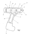
- a screwdriver according to the invention is shown schematically and designated overall by the reference numeral 10.
- the screwdriver 10 has a housing 12, which is designed pistol-shaped and at the lower end of a battery pack 16 is interchangeable added.
- the housing 12 has a handle 14 on which the screwdriver 10 are held and can be switched on and off by means of a switch button 28.
- a motor 18, a gear 20 and a clutch 22 are successively added, which together form the drive 17.
- the output side of the separating clutch 22 is connected to a tool spindle 24, on which a tool holder 26 for receiving a tool, for example a bit, is provided.
- the motor 18 drives the transmission 20.
- the transmission 20 is finally coupled via the separating clutch 22 with the tool spindle 24.
- the screwdriver 10 is controlled by a central control 30, which is received in the handle 14 and is connected via suitable lines to the accumulator package 16, the shift key 28, the motor 18, the transmission 20 and the disconnect clutch 22.
- a speed sensor 32 is further provided, which is formed for example as a Hall element and is also coupled to the controller 30 via suitable lines.
- the transmission 20 may, as for example from EP 0 320 723 A2 which is fully incorporated herein by reference, as a planetary gear be formed and be provided with a torque shutdown.
- switch 34 Upon reaching a certain torque coupled to the gear 20 switch 34 is actuated via a rotating fork and leads to the shutdown of the motor 18.
- a torsion bar can be provided. As soon as the torque exceeds a preset torque value, the restoring force of the torsion spring rod is overcome and the shift fork is twisted, which leads to the operation of the switch 34.
- the separating clutch 22 may be provided, via which, upon reaching a predetermined torque, the connection between the tool spindle 24 and the gear 20 is released by disengaging the separating clutch 22.
- Such tripping couplings have long been known in the art, for example, on the EP 0 990 488 A2 which is incorporated by reference in its entirety.
- the separating clutch 22 can be monitored and a disengagement of the coupling half can be registered, which in turn can be used mechanically for actuating a switch.
- the speed of the motor 18 is controlled by the controller 30 digital or analog.
- For speed monitoring of the speed sensor 32 is provided which emits a pulse at each revolution of the motor shaft, which is supplied to a counter in the controller 30. If the number of pulses emitted by the sensor per unit time remains the same, the speed n of the motor 18 is constant. If the number of pulses per unit of time increases, the speed n increases, but decreases per unit of time, so the speed n drops. The number of pulses per unit time is used as the actual size or input from the controller 30.
- the screwdriver 10 is operated with a load-dependent motor characteristic.
- Fig. 2a is a flowchart 50 showing a part of the operation of the controller 30.
- the speed n is measured or calculated and the values stored in a ring buffer. For example, a speed measurement per millisecond can be done.
- a monitoring of a shutdown criterion is constantly carried out, which takes place in the course of a separate flowchart 90, which in Fig. 2b ) is shown separately, but in the flowchart according to Fig. 2a ) is integrated and the regelmä-ßig, eg every 5 milliseconds, queried to turn off the screwdriver 10 as soon as the switch-off criterion is reached.
- an acceleration process 52 begins first. It is accelerated until the idling speed n 1 is reached.
- the acceleration process 52 is designed so that it is as pleasant as possible for the user, that is, a soft start is performed. As a result, high current peaks during startup are avoided.
- the current speed value n is stored in the subsequent step 56 ("STORE n").
- step 62 it is again queried whether the rotational speed has fallen by at least the amount x 1 compared to the previous rotational speed. If this is not the case, then the screwdriver 10 is further operated at the same speed n 1 , that is, it is branched back to step 60. If, on the other hand, it is determined in query 62 that a significant drop in rotational speed has occurred (n (i) + x 1 ⁇ n (im)), a deceleration ("RET") takes place in step 66.
- RET deceleration
- the current speed n (i) is compared not only with a past speed n (im). Rather, the current speed n (i) is compared with several different speeds in the past, speeds. For each comparison, there is a specific value x 1 by which the speed must be dropped for deceleration to take place.
- x 1 there is a specific value x 1 by which the speed must be dropped for deceleration to take place.
- a soft screw is determined only after a long time, since in this case the speed drop is not very large compared to a soft screwing or this assumes a significant value only after a long time.
- An advantage of this method is that the speed is always lowered in time before it comes to triggering the separator (mechanical disconnect clutch). This is, based on the achievement of the headrest of a screw, in a hard screwing very early and in a soft screw a little later. This minimizes the tightening time and increases accuracy.
- step 66 takes place until the rotational speed has fallen to a value n 2 which is lower than the idling rotational speed n 1 . If the speed n 2 has not yet been reached, it is further delayed according to step 66. If the speed n 2 has been reached, this is regulated in step 68 ("CONTROL n").
- the mentioned braking process can be done either by "active braking” or by simply reducing or removing the power supply.
- n 2 If the speed n 2 is reached, it is held for a certain time, for example 30 ms-100 ms, preferably 60 milliseconds, or for a certain angle of rotation ⁇ , as checked in the query 70. If the time t has expired or the angle of rotation ⁇ has been reached, an acceleration ("ACC") takes place again in step 72.
- ACC acceleration
- n 1 is reached again, which is checked in the query 76. If the idle speed n 1 is reached again, it continues with step 60. If the idle speed n 1 is not reached, it is checked in the query step 78, if the current speed deviates at least by a certain amount x 2 from the idle speed n 1 (n> n 1 -x 2 ). If this is not the case, then further accelerated in step 72. If the speed has reached the desired amount, the current speed is stored in step 80 ("STORE n").
- step 74 it is again checked whether the braking criterion has been reached (n (i) + x 1 ⁇ n (im)). If this is the case, the braking is initiated according to step 66. Otherwise, it is further accelerated in step 72.
- the flowchart 50 described above is the flowchart 90 according to Fig. 2b ), which is polled regularly, eg every 1 to 30 ms, preferably every 5 milliseconds. Starting from any previous step 92 from the flowchart 50, a query is made in branch 94 as to whether the shutdown criterion has been reached.
- Abschaltkriterium it is checked as Abschaltkriterium whether a preset torque is reached. This can be monitored by triggering the separating clutch 22 with a corresponding sensor. If there is no disconnect clutch 22, this could be checked, for example, by means of a torque sensor (e.g., strain gauges).
- a torque sensor e.g., strain gauges
- the flowchart 50 is continued. If the switch-off criterion is reached, the motor power is fully activated in the subsequent step 96 ("PWM 100%"), that is, the pulse width modulation is fully controlled. This is useful in connection with a disconnect clutch, since, especially when the accumulator 16 is almost exhausted, a mechanical disconnect clutch does not properly or not safely triggers. A correct release results by skipping a cam. By this brief full control of the motor 18 as a safe release of the clutch 22 is ensured.
- step 98 After a deceleration step 98 lasting, for example, 10 ms-300 ms, preferably 50 ms (or a rotation angle of the separating clutch of 30 ° to 120 °, preferably 100 °), the motor is subsequently stopped in step 100 ("STOP motor”). ). This completes the cycle at 102 ("STOP").
- the speed level for the idle speed n 1 is about 800 to 1500 1 / min, preferably about 1000 1 / min, while the lowered second speed n 2 in the range of 200 to 400 1 / min, preferably about 300 1 / min is, in each case measured on the separating clutch 22 and the tool spindle 24th
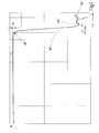
- Fig. 3 shows the application of a soft screwing operation.
- the tool spindle 24 is first driven at the speed n 1 (see step 60). Subsequently, a speed drop ⁇ n is detected. As soon as it exceeds the predetermined value x 1 in step 62, the braking process begins, which is indicated by the arrow "RET". The braking process RET is continued until the speed n 2 is reached. This is controlled in step 68 for a certain period of time t or a certain angle of rotation ⁇ . After this time, an acceleration is again in step 72, and at most up to the speed n 1 .
- step 72 If, however, the speed n is still smaller than the speed n 1 minus a specific difference x 2 , according to query 78 in step 72 the speed is further accelerated. In the illustrated soft screw the speed increases so during the final tightening of the screw gradually until, due to the increasing torque returns to a natural drop in speed. At the point "OFF" the switch-off criterion according to branch 94 is reached. That is, the disconnect clutch triggers, and the sequence of steps 96, 98, 100, 102 is passed through until the motor 18 is turned off and the screwing operation is completed.
- Fig. 4 is shown a hard screw case.
- step 52 After the start 51 is first accelerated according to step 52 to the idle speed n 1 and the speed value then stored according to step 60. If it is determined in the subsequent query in step 62 that the speed falls within a certain time by a certain amount, as by ⁇ n in Fig. 4 indicated or n (i) + x 1 ⁇ n (im) in Fig. 2 , the braking is initiated according to step 66, as in Fig. 4 indicated by the arrow "RET". The braking process is continued until finally the speed n 2 is reached or fallen below and is regulated according to step 68.
- step 70 an expiring acceleration occurs again after the predetermined time has elapsed, until finally the switch-off criterion according to step 94 is reached and in which the arrow "OFF" in FIG Fig. 4 designated point the shutdown via the steps 96, 98, 100, 102 according to Fig. 2b ) is initiated.
- the idling speed n 1 is initially maintained (step 54).
- a speed drop ⁇ n is detected which exceeds the value x 1 at a certain point in time, which triggers the braking according to step 66, as indicated by the arrow "RET" in FIG Fig. 5 is indicated.
- the braking is continued until finally the speed n 2 is reached or fallen below and is controlled according to step 68 until a predetermined time t or a predetermined rotational angle ⁇ is exceeded.
- an acceleration "ACC" takes place according to step 72, until finally the idling speed n 1 is reached again and this is followed by a hard or soft screw.
- the speed is not lowered to zero or even a short-term drive in the opposite direction of rotation is performed before an acceleration takes place again. Rather, according to the invention, the speed is reduced in the case of deceleration only up to a predetermined positive speed value n 2 , before either an acceleration or a shutdown follows.
Landscapes
- Engineering & Computer Science (AREA)
- Mechanical Engineering (AREA)
- Details Of Spanners, Wrenches, And Screw Drivers And Accessories (AREA)
- Control Of Electric Motors In General (AREA)
Applications Claiming Priority (1)
| Application Number | Priority Date | Filing Date | Title |
|---|---|---|---|
| DE201010024920 DE102010024920A1 (de) | 2010-06-18 | 2010-06-18 | Schrauber |
Publications (3)
| Publication Number | Publication Date |
|---|---|
| EP2397258A2 true EP2397258A2 (fr) | 2011-12-21 |
| EP2397258A3 EP2397258A3 (fr) | 2014-05-07 |
| EP2397258B1 EP2397258B1 (fr) | 2015-09-23 |
Family
ID=44789233
Family Applications (1)
| Application Number | Title | Priority Date | Filing Date |
|---|---|---|---|
| EP11164030.6A Active EP2397258B1 (fr) | 2010-06-18 | 2011-04-28 | Visseuse |
Country Status (3)
| Country | Link |
|---|---|
| US (1) | US8985237B2 (fr) |
| EP (1) | EP2397258B1 (fr) |
| DE (1) | DE102010024920A1 (fr) |
Cited By (2)
| Publication number | Priority date | Publication date | Assignee | Title |
|---|---|---|---|---|
| US20200130152A1 (en) * | 2017-03-13 | 2020-04-30 | Liebherr-Components Biberach Gmbh | Method And Device For Tightening Screw Joints |
| WO2021244790A1 (fr) * | 2020-06-04 | 2021-12-09 | Festool Gmbh | Dispositif d'outil électrique et procédé |
Families Citing this family (20)
| Publication number | Priority date | Publication date | Assignee | Title |
|---|---|---|---|---|
| DE102011005079A1 (de) * | 2011-03-04 | 2012-09-06 | Hilti Aktiengesellschaft | Setzverfahren für einen Spreizanker und Schlagschrauber zum Setzen eines Spreizankers |
| DE102012108332A1 (de) * | 2012-08-29 | 2014-03-06 | Hs-Technik Gmbh | Verfahren für die Regelung der Drehzahl eines Schraubwerkzeugs |
| FR2996483B1 (fr) * | 2012-10-05 | 2015-04-17 | Renault Georges Ets | Dispositif de vissage sans reaction dans la poignee |
| DE102012218272A1 (de) * | 2012-10-08 | 2014-04-10 | Robert Bosch Gmbh | Handwerkzeugmaschine |
| DE102013212546B4 (de) * | 2013-06-28 | 2023-12-14 | Robert Bosch Gmbh | Handwerkzeugmaschinenbedienvorrichtung |
| JP6322387B2 (ja) * | 2013-11-05 | 2018-05-09 | Tone株式会社 | 締付装置及び締付方法 |
| DE102014211891A1 (de) * | 2014-06-20 | 2015-12-24 | Robert Bosch Gmbh | Verfahren zum Betreiben eines Elektrowerkzeuges |
| WO2016196979A1 (fr) | 2015-06-05 | 2016-12-08 | Ingersoll-Rand Company | Outils de percussion avec fonctionnalités d'alignement de couronne dentée |
| WO2016196918A1 (fr) | 2015-06-05 | 2016-12-08 | Ingersoll-Rand Company | Interfaces utilisateur d'outil électrique |
| US11260517B2 (en) | 2015-06-05 | 2022-03-01 | Ingersoll-Rand Industrial U.S., Inc. | Power tool housings |
| WO2016196984A1 (fr) * | 2015-06-05 | 2016-12-08 | Ingersoll-Rand Company | Machines portatives à moteur à modes de fonctionnement sélectionnables par l'utilisateur |
| JP6981744B2 (ja) | 2016-10-07 | 2021-12-17 | 株式会社マキタ | ハンマドリル |
| JP6757226B2 (ja) | 2016-10-07 | 2020-09-16 | 株式会社マキタ | 電動工具 |
| JP6863705B2 (ja) * | 2016-10-07 | 2021-04-21 | 株式会社マキタ | 電動工具 |
| DE102017223589A1 (de) * | 2017-12-21 | 2019-06-27 | Zf Friedrichshafen Ag | Verfahren zur Montage einer Schraube, Montagevorrichtung sowie Steuerungsvorrichtung |
| DE102018201074A1 (de) * | 2018-01-24 | 2019-07-25 | Robert Bosch Gmbh | Verfahren zur Steuerung eines Schlagschraubers |
| DE102018114275A1 (de) * | 2018-06-14 | 2019-12-19 | Metabowerke Gmbh | Verfahren zur Steuerung des Drehmoments eines Elektrohandwerkzeuggeräts |
| FR3105050B1 (fr) * | 2019-12-19 | 2021-12-10 | Renault Georges Ets | Procédé de contrôle d’un niveau de qualité de vissage d’une visseuse, dispositif associé et programme mettant en œuvre le procédé. |
| DE102021119958A1 (de) | 2021-08-02 | 2023-03-16 | Wagner Vermögensverwaltungs-GmbH & Co. Kommanditgesellschaft | Verfahren zur Regelung eines Drehschraubers |
| DE102021208653A1 (de) | 2021-08-09 | 2023-02-09 | Robert Bosch Gesellschaft mit beschränkter Haftung | Verfahren zur Steuerung einer Handwerkzeugmaschine |
Citations (4)
| Publication number | Priority date | Publication date | Assignee | Title |
|---|---|---|---|---|
| EP0320723A2 (fr) | 1987-12-18 | 1989-06-21 | C. & E. FEIN GmbH & Co. | Machine avec réglage du couple variable |
| EP0990488A2 (fr) | 1998-09-30 | 2000-04-05 | C. & E. FEIN GmbH & Co. | Tournevis motorisé |
| EP1785231A2 (fr) | 2005-11-14 | 2007-05-16 | C. & E. FEIN GmbH | Outil de vissage à régulation de vitesse de rotation et méthode de régulation de vitesse pour un outil de vissage |
| DE102008033866A1 (de) | 2008-07-19 | 2010-01-28 | Festool Gmbh | Steuerungseinrichtung für einen elektrischen Antriebsmotor und Werkzeugmaschine |
Family Cites Families (6)
| Publication number | Priority date | Publication date | Assignee | Title |
|---|---|---|---|---|
| JP2943457B2 (ja) * | 1991-09-30 | 1999-08-30 | トヨタ自動車株式会社 | ナットランナ |
| US5215270A (en) * | 1992-06-18 | 1993-06-01 | Cooper Industries, Inc. | Method for tightening a fastener |
| SE506118C2 (sv) * | 1993-09-02 | 1997-11-10 | Atlas Copco Tools Ab | Metod för åtdragning av gängade förband till en önskad förspänningsnivå med hjälp av en manuellt manövrerad kraftmutterdragare innefattande en nedgängningsfas och en förspänningsfas, avkänning av momentmotståndet i förbandet samt avbrytande av rotationen vid uppnådd önskad förspänningsnivå |
| US5637968A (en) * | 1993-10-25 | 1997-06-10 | The Stanley Works | Power tool with automatic downshift feature |
| JP4339275B2 (ja) * | 2005-05-12 | 2009-10-07 | 株式会社エスティック | インパクト式のネジ締め装置の制御方法および装置 |
| DE102006017193A1 (de) * | 2006-04-12 | 2007-10-25 | Robert Bosch Gmbh | Verfahren zum Anziehen einer Schraubverbindung und Schraubwerkzeug |
-
2010
- 2010-06-18 DE DE201010024920 patent/DE102010024920A1/de not_active Withdrawn
-
2011
- 2011-04-28 EP EP11164030.6A patent/EP2397258B1/fr active Active
- 2011-06-17 US US13/163,380 patent/US8985237B2/en active Active
Patent Citations (4)
| Publication number | Priority date | Publication date | Assignee | Title |
|---|---|---|---|---|
| EP0320723A2 (fr) | 1987-12-18 | 1989-06-21 | C. & E. FEIN GmbH & Co. | Machine avec réglage du couple variable |
| EP0990488A2 (fr) | 1998-09-30 | 2000-04-05 | C. & E. FEIN GmbH & Co. | Tournevis motorisé |
| EP1785231A2 (fr) | 2005-11-14 | 2007-05-16 | C. & E. FEIN GmbH | Outil de vissage à régulation de vitesse de rotation et méthode de régulation de vitesse pour un outil de vissage |
| DE102008033866A1 (de) | 2008-07-19 | 2010-01-28 | Festool Gmbh | Steuerungseinrichtung für einen elektrischen Antriebsmotor und Werkzeugmaschine |
Cited By (3)
| Publication number | Priority date | Publication date | Assignee | Title |
|---|---|---|---|---|
| US20200130152A1 (en) * | 2017-03-13 | 2020-04-30 | Liebherr-Components Biberach Gmbh | Method And Device For Tightening Screw Joints |
| US11529718B2 (en) * | 2017-03-13 | 2022-12-20 | Liebherr-Components Biberach Gmbh | Method and device for tightening screw joints |
| WO2021244790A1 (fr) * | 2020-06-04 | 2021-12-09 | Festool Gmbh | Dispositif d'outil électrique et procédé |
Also Published As
| Publication number | Publication date |
|---|---|
| EP2397258B1 (fr) | 2015-09-23 |
| DE102010024920A1 (de) | 2011-12-22 |
| US20110308827A1 (en) | 2011-12-22 |
| US8985237B2 (en) | 2015-03-24 |
| EP2397258A3 (fr) | 2014-05-07 |
Similar Documents
| Publication | Publication Date | Title |
|---|---|---|
| EP2397258B1 (fr) | Visseuse | |
| EP3157711B1 (fr) | Procédé permettant de faire fonctionner un outil électrique | |
| EP3960375A2 (fr) | Procédé de commande d'un moteur électrique d'un outil électrique | |
| DE102015001982B4 (de) | Drehschlagwerkzeug | |
| EP2443011B1 (fr) | Procédé et dispositif de détermination du début d'une phase de démarrage d'un moteur à combustion interne dans un véhicule hybride | |
| EP2338646B1 (fr) | Procédé de commande pour une machine-outil manuelle | |
| EP2527091B1 (fr) | Tournevis et procédé de commande d'un tournevis | |
| DE102005030328B4 (de) | Kraftsensor und motor-getriebene Parkbremsvorrichtung, die denselben verwendet | |
| DE102014009126B4 (de) | Elektronisches Parkbremssystem und Verfahren zur Steuerung desselben | |
| DE102007021985B4 (de) | Fahrpedal-System | |
| DE102016115538A1 (de) | Drehschlagwerkzeug und Verfahren zum Steuern desselben | |
| DE2541930A1 (de) | Mehrstufige bolzen-anziehanordnung | |
| DE2541523B2 (de) | Schraubvorrichtung | |
| EP2243599A2 (fr) | Vis à percussion et procédé de commande pour une vis à percussion | |
| EP1785231A2 (fr) | Outil de vissage à régulation de vitesse de rotation et méthode de régulation de vitesse pour un outil de vissage | |
| DE19620782A1 (de) | Verfahren zur Herstellung einer Schraubverbindung und Vorrichtung hierfür | |
| DE102015210431A1 (de) | Verfahren zum Ansteuern einer Feststellbremse in einem Fahrzeug | |
| EP2376307B1 (fr) | Procédé et dispositif pour commander une chaîne cinématique | |
| DE112016002036B4 (de) | Verfahren zur Steuerung einer Kupplung eines Fahrzeuges nach Beendigung eines Segelbetriebes des Fahrzeuges | |
| DE102007045695A1 (de) | Hydropneumatischer Impulsschrauber und Verfahren zur Steuerung eines hydropneumatischen Impulsschraubers | |
| WO2023016811A1 (fr) | Procédé de commande d'outil électrique portatif | |
| EP1880129B1 (fr) | Procede et dispositif de commande d'un changement de vitesse a l'arret d'une boite de vitesses automatique | |
| DE102016212520B4 (de) | Verfahren zum Betreiben eines Elektrowerkzeuges | |
| EP2100050A1 (fr) | Procédé de commande d'un embrayage à friction d'un véhicule | |
| AT519142A2 (de) | Verfahren und Vorrichtung zum Abbauen elastisch gespeicherter Energie |
Legal Events
| Date | Code | Title | Description |
|---|---|---|---|
| AK | Designated contracting states |
Kind code of ref document: A2 Designated state(s): AL AT BE BG CH CY CZ DE DK EE ES FI FR GB GR HR HU IE IS IT LI LT LU LV MC MK MT NL NO PL PT RO RS SE SI SK SM TR |
|
| AX | Request for extension of the european patent |
Extension state: BA ME |
|
| PUAI | Public reference made under article 153(3) epc to a published international application that has entered the european phase |
Free format text: ORIGINAL CODE: 0009012 |
|
| PUAL | Search report despatched |
Free format text: ORIGINAL CODE: 0009013 |
|
| AK | Designated contracting states |
Kind code of ref document: A3 Designated state(s): AL AT BE BG CH CY CZ DE DK EE ES FI FR GB GR HR HU IE IS IT LI LT LU LV MC MK MT NL NO PL PT RO RS SE SI SK SM TR |
|
| AX | Request for extension of the european patent |
Extension state: BA ME |
|
| RIC1 | Information provided on ipc code assigned before grant |
Ipc: B25B 21/00 20060101ALI20140403BHEP Ipc: B25B 23/147 20060101ALI20140403BHEP Ipc: B23P 19/06 20060101ALI20140403BHEP Ipc: B25B 23/14 20060101AFI20140403BHEP |
|
| 17P | Request for examination filed |
Effective date: 20140916 |
|
| RBV | Designated contracting states (corrected) |
Designated state(s): AL AT BE BG CH CY CZ DE DK EE ES FI FR GB GR HR HU IE IS IT LI LT LU LV MC MK MT NL NO PL PT RO RS SE SI SK SM TR |
|
| GRAP | Despatch of communication of intention to grant a patent |
Free format text: ORIGINAL CODE: EPIDOSNIGR1 |
|
| RIC1 | Information provided on ipc code assigned before grant |
Ipc: B25B 23/147 20060101ALI20150313BHEP Ipc: B25B 21/00 20060101ALI20150313BHEP Ipc: B25B 23/14 20060101AFI20150313BHEP Ipc: B23P 19/06 20060101ALI20150313BHEP |
|
| INTG | Intention to grant announced |
Effective date: 20150415 |
|
| GRAS | Grant fee paid |
Free format text: ORIGINAL CODE: EPIDOSNIGR3 |
|
| GRAA | (expected) grant |
Free format text: ORIGINAL CODE: 0009210 |
|
| AK | Designated contracting states |
Kind code of ref document: B1 Designated state(s): AL AT BE BG CH CY CZ DE DK EE ES FI FR GB GR HR HU IE IS IT LI LT LU LV MC MK MT NL NO PL PT RO RS SE SI SK SM TR |
|
| REG | Reference to a national code |
Ref country code: GB Ref legal event code: FG4D Free format text: NOT ENGLISH |
|
| REG | Reference to a national code |
Ref country code: CH Ref legal event code: EP |
|
| REG | Reference to a national code |
Ref country code: AT Ref legal event code: REF Ref document number: 750968 Country of ref document: AT Kind code of ref document: T Effective date: 20151015 |
|
| REG | Reference to a national code |
Ref country code: IE Ref legal event code: FG4D Free format text: LANGUAGE OF EP DOCUMENT: GERMAN |
|
| REG | Reference to a national code |
Ref country code: DE Ref legal event code: R096 Ref document number: 502011007917 Country of ref document: DE |
|
| REG | Reference to a national code |
Ref country code: NL Ref legal event code: MP Effective date: 20150923 |
|
| PG25 | Lapsed in a contracting state [announced via postgrant information from national office to epo] |
Ref country code: LT Free format text: LAPSE BECAUSE OF FAILURE TO SUBMIT A TRANSLATION OF THE DESCRIPTION OR TO PAY THE FEE WITHIN THE PRESCRIBED TIME-LIMIT Effective date: 20150923 Ref country code: FI Free format text: LAPSE BECAUSE OF FAILURE TO SUBMIT A TRANSLATION OF THE DESCRIPTION OR TO PAY THE FEE WITHIN THE PRESCRIBED TIME-LIMIT Effective date: 20150923 Ref country code: GR Free format text: LAPSE BECAUSE OF FAILURE TO SUBMIT A TRANSLATION OF THE DESCRIPTION OR TO PAY THE FEE WITHIN THE PRESCRIBED TIME-LIMIT Effective date: 20151224 Ref country code: LV Free format text: LAPSE BECAUSE OF FAILURE TO SUBMIT A TRANSLATION OF THE DESCRIPTION OR TO PAY THE FEE WITHIN THE PRESCRIBED TIME-LIMIT Effective date: 20150923 Ref country code: NO Free format text: LAPSE BECAUSE OF FAILURE TO SUBMIT A TRANSLATION OF THE DESCRIPTION OR TO PAY THE FEE WITHIN THE PRESCRIBED TIME-LIMIT Effective date: 20151223 |
|
| REG | Reference to a national code |
Ref country code: LT Ref legal event code: MG4D |
|
| PG25 | Lapsed in a contracting state [announced via postgrant information from national office to epo] |
Ref country code: HR Free format text: LAPSE BECAUSE OF FAILURE TO SUBMIT A TRANSLATION OF THE DESCRIPTION OR TO PAY THE FEE WITHIN THE PRESCRIBED TIME-LIMIT Effective date: 20150923 Ref country code: RS Free format text: LAPSE BECAUSE OF FAILURE TO SUBMIT A TRANSLATION OF THE DESCRIPTION OR TO PAY THE FEE WITHIN THE PRESCRIBED TIME-LIMIT Effective date: 20150923 Ref country code: SE Free format text: LAPSE BECAUSE OF FAILURE TO SUBMIT A TRANSLATION OF THE DESCRIPTION OR TO PAY THE FEE WITHIN THE PRESCRIBED TIME-LIMIT Effective date: 20150923 |
|
| PG25 | Lapsed in a contracting state [announced via postgrant information from national office to epo] |
Ref country code: NL Free format text: LAPSE BECAUSE OF FAILURE TO SUBMIT A TRANSLATION OF THE DESCRIPTION OR TO PAY THE FEE WITHIN THE PRESCRIBED TIME-LIMIT Effective date: 20150923 |
|
| PG25 | Lapsed in a contracting state [announced via postgrant information from national office to epo] |
Ref country code: CZ Free format text: LAPSE BECAUSE OF FAILURE TO SUBMIT A TRANSLATION OF THE DESCRIPTION OR TO PAY THE FEE WITHIN THE PRESCRIBED TIME-LIMIT Effective date: 20150923 Ref country code: SK Free format text: LAPSE BECAUSE OF FAILURE TO SUBMIT A TRANSLATION OF THE DESCRIPTION OR TO PAY THE FEE WITHIN THE PRESCRIBED TIME-LIMIT Effective date: 20150923 Ref country code: IT Free format text: LAPSE BECAUSE OF FAILURE TO SUBMIT A TRANSLATION OF THE DESCRIPTION OR TO PAY THE FEE WITHIN THE PRESCRIBED TIME-LIMIT Effective date: 20150923 Ref country code: IS Free format text: LAPSE BECAUSE OF FAILURE TO SUBMIT A TRANSLATION OF THE DESCRIPTION OR TO PAY THE FEE WITHIN THE PRESCRIBED TIME-LIMIT Effective date: 20160123 Ref country code: EE Free format text: LAPSE BECAUSE OF FAILURE TO SUBMIT A TRANSLATION OF THE DESCRIPTION OR TO PAY THE FEE WITHIN THE PRESCRIBED TIME-LIMIT Effective date: 20150923 Ref country code: ES Free format text: LAPSE BECAUSE OF FAILURE TO SUBMIT A TRANSLATION OF THE DESCRIPTION OR TO PAY THE FEE WITHIN THE PRESCRIBED TIME-LIMIT Effective date: 20150923 |
|
| PG25 | Lapsed in a contracting state [announced via postgrant information from national office to epo] |
Ref country code: PT Free format text: LAPSE BECAUSE OF FAILURE TO SUBMIT A TRANSLATION OF THE DESCRIPTION OR TO PAY THE FEE WITHIN THE PRESCRIBED TIME-LIMIT Effective date: 20160125 Ref country code: RO Free format text: LAPSE BECAUSE OF FAILURE TO SUBMIT A TRANSLATION OF THE DESCRIPTION OR TO PAY THE FEE WITHIN THE PRESCRIBED TIME-LIMIT Effective date: 20150923 Ref country code: PL Free format text: LAPSE BECAUSE OF FAILURE TO SUBMIT A TRANSLATION OF THE DESCRIPTION OR TO PAY THE FEE WITHIN THE PRESCRIBED TIME-LIMIT Effective date: 20150923 |
|
| REG | Reference to a national code |
Ref country code: DE Ref legal event code: R097 Ref document number: 502011007917 Country of ref document: DE |
|
| PLBE | No opposition filed within time limit |
Free format text: ORIGINAL CODE: 0009261 |
|
| STAA | Information on the status of an ep patent application or granted ep patent |
Free format text: STATUS: NO OPPOSITION FILED WITHIN TIME LIMIT |
|
| 26N | No opposition filed |
Effective date: 20160624 |
|
| PG25 | Lapsed in a contracting state [announced via postgrant information from national office to epo] |
Ref country code: DK Free format text: LAPSE BECAUSE OF FAILURE TO SUBMIT A TRANSLATION OF THE DESCRIPTION OR TO PAY THE FEE WITHIN THE PRESCRIBED TIME-LIMIT Effective date: 20150923 Ref country code: BE Free format text: LAPSE BECAUSE OF NON-PAYMENT OF DUE FEES Effective date: 20160430 |
|
| PG25 | Lapsed in a contracting state [announced via postgrant information from national office to epo] |
Ref country code: SI Free format text: LAPSE BECAUSE OF FAILURE TO SUBMIT A TRANSLATION OF THE DESCRIPTION OR TO PAY THE FEE WITHIN THE PRESCRIBED TIME-LIMIT Effective date: 20150923 |
|
| REG | Reference to a national code |
Ref country code: CH Ref legal event code: PL |
|
| GBPC | Gb: european patent ceased through non-payment of renewal fee |
Effective date: 20160428 |
|
| PG25 | Lapsed in a contracting state [announced via postgrant information from national office to epo] |
Ref country code: LU Free format text: LAPSE BECAUSE OF FAILURE TO SUBMIT A TRANSLATION OF THE DESCRIPTION OR TO PAY THE FEE WITHIN THE PRESCRIBED TIME-LIMIT Effective date: 20160428 |
|
| REG | Reference to a national code |
Ref country code: IE Ref legal event code: MM4A |
|
| REG | Reference to a national code |
Ref country code: FR Ref legal event code: ST Effective date: 20161230 |
|
| PG25 | Lapsed in a contracting state [announced via postgrant information from national office to epo] |
Ref country code: LI Free format text: LAPSE BECAUSE OF NON-PAYMENT OF DUE FEES Effective date: 20160430 Ref country code: CH Free format text: LAPSE BECAUSE OF NON-PAYMENT OF DUE FEES Effective date: 20160430 Ref country code: FR Free format text: LAPSE BECAUSE OF NON-PAYMENT OF DUE FEES Effective date: 20160502 Ref country code: GB Free format text: LAPSE BECAUSE OF NON-PAYMENT OF DUE FEES Effective date: 20160428 |
|
| PG25 | Lapsed in a contracting state [announced via postgrant information from national office to epo] |
Ref country code: IE Free format text: LAPSE BECAUSE OF NON-PAYMENT OF DUE FEES Effective date: 20160428 |
|
| REG | Reference to a national code |
Ref country code: AT Ref legal event code: MM01 Ref document number: 750968 Country of ref document: AT Kind code of ref document: T Effective date: 20160428 |
|
| PG25 | Lapsed in a contracting state [announced via postgrant information from national office to epo] |
Ref country code: AT Free format text: LAPSE BECAUSE OF NON-PAYMENT OF DUE FEES Effective date: 20160428 |
|
| PG25 | Lapsed in a contracting state [announced via postgrant information from national office to epo] |
Ref country code: CY Free format text: LAPSE BECAUSE OF FAILURE TO SUBMIT A TRANSLATION OF THE DESCRIPTION OR TO PAY THE FEE WITHIN THE PRESCRIBED TIME-LIMIT Effective date: 20150923 Ref country code: HU Free format text: LAPSE BECAUSE OF FAILURE TO SUBMIT A TRANSLATION OF THE DESCRIPTION OR TO PAY THE FEE WITHIN THE PRESCRIBED TIME-LIMIT; INVALID AB INITIO Effective date: 20110428 Ref country code: SM Free format text: LAPSE BECAUSE OF FAILURE TO SUBMIT A TRANSLATION OF THE DESCRIPTION OR TO PAY THE FEE WITHIN THE PRESCRIBED TIME-LIMIT Effective date: 20150923 |
|
| PG25 | Lapsed in a contracting state [announced via postgrant information from national office to epo] |
Ref country code: MK Free format text: LAPSE BECAUSE OF FAILURE TO SUBMIT A TRANSLATION OF THE DESCRIPTION OR TO PAY THE FEE WITHIN THE PRESCRIBED TIME-LIMIT Effective date: 20150923 Ref country code: TR Free format text: LAPSE BECAUSE OF FAILURE TO SUBMIT A TRANSLATION OF THE DESCRIPTION OR TO PAY THE FEE WITHIN THE PRESCRIBED TIME-LIMIT Effective date: 20150923 Ref country code: MT Free format text: LAPSE BECAUSE OF FAILURE TO SUBMIT A TRANSLATION OF THE DESCRIPTION OR TO PAY THE FEE WITHIN THE PRESCRIBED TIME-LIMIT Effective date: 20150923 Ref country code: MC Free format text: LAPSE BECAUSE OF FAILURE TO SUBMIT A TRANSLATION OF THE DESCRIPTION OR TO PAY THE FEE WITHIN THE PRESCRIBED TIME-LIMIT Effective date: 20150923 |
|
| PG25 | Lapsed in a contracting state [announced via postgrant information from national office to epo] |
Ref country code: BG Free format text: LAPSE BECAUSE OF FAILURE TO SUBMIT A TRANSLATION OF THE DESCRIPTION OR TO PAY THE FEE WITHIN THE PRESCRIBED TIME-LIMIT Effective date: 20150923 |
|
| PG25 | Lapsed in a contracting state [announced via postgrant information from national office to epo] |
Ref country code: AL Free format text: LAPSE BECAUSE OF FAILURE TO SUBMIT A TRANSLATION OF THE DESCRIPTION OR TO PAY THE FEE WITHIN THE PRESCRIBED TIME-LIMIT Effective date: 20150923 |
|
| REG | Reference to a national code |
Ref country code: DE Ref legal event code: R082 Ref document number: 502011007917 Country of ref document: DE |
|
| PGFP | Annual fee paid to national office [announced via postgrant information from national office to epo] |
Ref country code: DE Payment date: 20230418 Year of fee payment: 13 |