EP2397178B1 - Inhalationsvorrichtung - Google Patents
Inhalationsvorrichtung Download PDFInfo
- Publication number
- EP2397178B1 EP2397178B1 EP11168488.2A EP11168488A EP2397178B1 EP 2397178 B1 EP2397178 B1 EP 2397178B1 EP 11168488 A EP11168488 A EP 11168488A EP 2397178 B1 EP2397178 B1 EP 2397178B1
- Authority
- EP
- European Patent Office
- Prior art keywords
- housing
- sensor
- wall portion
- discharge
- sensor wall
- Prior art date
- Legal status (The legal status is an assumption and is not a legal conclusion. Google has not performed a legal analysis and makes no representation as to the accuracy of the status listed.)
- Active
Links
Images
Classifications
-
- A—HUMAN NECESSITIES
- A61—MEDICAL OR VETERINARY SCIENCE; HYGIENE
- A61M—DEVICES FOR INTRODUCING MEDIA INTO, OR ONTO, THE BODY; DEVICES FOR TRANSDUCING BODY MEDIA OR FOR TAKING MEDIA FROM THE BODY; DEVICES FOR PRODUCING OR ENDING SLEEP OR STUPOR
- A61M15/00—Inhalators
- A61M15/009—Inhalators using medicine packages with incorporated spraying means, e.g. aerosol cans
-
- A—HUMAN NECESSITIES
- A61—MEDICAL OR VETERINARY SCIENCE; HYGIENE
- A61M—DEVICES FOR INTRODUCING MEDIA INTO, OR ONTO, THE BODY; DEVICES FOR TRANSDUCING BODY MEDIA OR FOR TAKING MEDIA FROM THE BODY; DEVICES FOR PRODUCING OR ENDING SLEEP OR STUPOR
- A61M15/00—Inhalators
- A61M15/0065—Inhalators with dosage or measuring devices
- A61M15/0068—Indicating or counting the number of dispensed doses or of remaining doses
- A61M15/008—Electronic counters
Definitions
- the invention relates to an inhalation device for oral administration of a pharmaceutical medium.
- a generic inhalation device has a housing with a mouthpiece, a container unit accommodated in an inhalation region of the housing with a medium container and an outlet connection with outlet opening displaceable with respect to the medium container for the purpose of a discharge operation and a discharge sensor for detecting the medium discharge.
- MDI Metal-DoseInhaler
- pMDI pressurized metered-dose inhaler
- They are used to administer drugs that are intended to enter the lung of the user for the purpose of treating respiratory diseases in an atomized form. They have said housing, in which said container unit is inserted.
- the housing has an air inlet that allows air to be sucked through the inhalation area of the housing through the mouthpiece, during which process the suction process is carried out is effected by medium from the medium container by displacing the medium container relative to the outlet port, so that the absorbed air is mixed with the atomized medium and inhaled and thus can reach the lungs.
- the discharge of medium from the medium container is effected by the relative displacement of the medium container relative to the outlet.
- the medium container in the case of generic inhalation devices, can protrude a little way out of the air inlet of the housing, so that it can be subjected to force manually directly in order to be displaced relative to the outlet connection inserted into a corresponding recess in the housing.
- Generic inhalation devices are provided with a discharge sensor for detecting the discharge operation, in particular for the purpose of counting the discharge operations. This makes it possible for a user to detect the number of remaining in the medium container doses of the medium and thus to be able to estimate how long the medium in the medium container still enough.
- the WO 1997/033640 A1 describes a pressure sensor which is arranged on a channel provided for the stipulateaustrag and makes the medium discharge thereby detectable. This design is comparatively complex and expensive.
- WO 1991/006334 A1 a design is known in which a mechanical detection of the discharge operation is achieved in that the movement of the medium container in the inhalation region of the Housing is detected.
- a comparable solution is also from the WO 1996/000595 A1 known.
- the WO 2005/009325 A2 contains a variety of designs, most of which also provide that in the inhalation of the housing a button is arranged, which is activated in the course of the displacement of the medium container in the inhalation area. From this document, it is also known to provide a button on the outside of the housing, which is inevitably manually mitbetätigt in the course of manual application of force to the medium container relative to the housing.
- the object of the invention is to develop a generic inhalation device to the effect that it can reliably detect the discharge operations.
- a cost-effective design should be achieved.
- a wall section delimiting the inhalation region and separating in particular from an environment or a receiving space for electronic components the sensor wall section having a receiving opening for the outlet nozzle is movable relative to a main section of the housing and during the displacement of the medium container within the wall Inhalation area is moved.
- This movement of the sensor wall section is detected by the discharge sensor instead of the direct detection of the movement of the medium container.
- the sensor wall portion is integrally connected to the main portion of the housing.
- An inhalation device has the features of the generic inhalation devices described above. It preferably has an electronic unit which is designed to evaluate the signals of the discharge sensor, which is designed in particular as a push-button.
- This electronics preferably comprises an integrated circuit, which serves in particular the counting of the discharge operations.
- it preferably comprises a battery as an energy store and an output unit, in particular in the form of a display, to which the number of already dispensed or still contained cans can be seen.
- the main portion of the housing on the other hand, the sensor wall portion is movable, includes those parts of the outer surface of the housing intended for holding the inhalation device as a particular cylindrical housing portion which surrounds the container unit, and all fixed thereto components of the housing, in particular the mouthpiece ,
- the sensor wall section is movable relative to this main section, being connected to the main section in such a way that it returns to a starting position after completion of a discharge operation and omission of the corresponding manual application of force.
- the formed as part of the housing sensor wall portion is made of the same material as the main portion, in particular made of plastic, and it is integrally connected at least with the surrounding parts of the main portion of the housing, wherein a connecting portion between the main portion and the sensor wall portion is deformable.
- This one-piece construction allows, in particular, easy manufacturability, since the sensor wall section can be provided directly during production of the housing. Furthermore, by means of this one-piece construction, the abovementioned automatic return of the sensor wall section to its starting position can be easily achieved by means of a corresponding elastic design of the connection region. Furthermore, the one-piece is also in view of a desired liquid-tightness of advantage. For this purpose, it is preferably further provided that the connecting region surrounding the sensor wall portion circumferentially and thereby connects the sensor wall portion liquid-tight with the main portion of the housing. In such a case, the connection region is preferably formed as a region with significantly reduced wall thickness in relation to the sensor wall section and the main section.
- the discharge sensor is preferably provided on the side of the sensor wall section facing away from the inhalation region. He is thereby arranged in a sheltered position. So there is no danger to damage the discharge sensor when inserting the container unit. In particular, it is also ensured in the above-described liquid-tight design of the connection region that the discharge sensor facing away from the inhalation region is not impaired by moisture present in the inhalation region.
- the sensor wall section always remains stationary during operation to the outlet port of the container unit.
- the sensor wall section has a receiving recess for the outlet nozzle and preferably has a discharge nozzle connected via a channel to the receiving recess. This discharge nozzle opens into the inhalation region of the housing and defines the region in which the medium from the medium container is mixed with the air absorbed by the user during operation.
- the sensor wall section is arranged below the container unit in the usual orientation of use of an MDI.
- the discharge sensor, the sensor wall section and the container unit are preferably matched to one another and arranged such that in the course of a displacement of the container unit relative to the main portion of the housing, the sensor wall section actuates the discharge sensor as soon as or before the discharge process starts from the medium container.
- This type of coordination ensures that even an incomplete discharge process, for example due to insufficient displacement of the medium container relative to the main portion of the housing, is registered by the discharge sensor and thus takes into account in a count of the discharge operations.
- a deviation of the determined on the basis of the count residual amount of the medium in the medium container compared to the actually remaining amount of the medium is possible only in the form that the amount of medium still contained in the medium container is underestimated. This prevents the situation that supposedly still medium in the medium container remains, this is actually no longer available.
- the discharge sensor which is preferably designed as a button, can be provided in particular on the main portion of the housing and be arranged so that a relative to a base of the probe displaceable probe surface is depressed in the course of actuation of the inhalation device by the sensor wall section.
- the discharge sensor is preferably on the inhalation area remote side of the sensor wall portion arranged. It is particularly advantageous if the housing has two sub-housings which can be coupled to one another by means of a coupling device, wherein a first sub-housing surrounds the inhalation area and has the sensor wall section and wherein a second sub-housing has the discharge sensor.
- the first sub-housing may be intended to be disposed of with a container unit together with it after use, while the second sub-housing having the discharge sensor and preferably all other electronic components of the inhalation device is reused.
- the discharge sensor is arranged on the second sub-housing so that a force application from the outside can trigger the sensor, wherein this force is effected in the coupled state of the sub-housing by the correspondingly arranged sensor wall section.
- the second sub-housing has a sensor which is suitable for detecting the coupling state of the two sub-housings.
- This can be a separate sensor.
- it may also be the Austragsensor be designed so that it can detect, for example, the deflection of its probe surface on the one hand, the coupling state and on the other, the displacement of the sensor wall section.
- the electronic components in particular the circuit provided for counting, are designed such that an actuation of the sensor provided for counting is only used for counting when the sub-housings are in the coupled state.
- the second sub-housing In such a design with two sub-housings, it is preferable for the second sub-housing to have an inner region which is delimited in the region of the discharge sensor by a shape-variable or displaceable wall section. This allows the electronics to be completely encapsulated.
- the discharge sensor is not unprotected on the outside of the second housing part in such a case, even in the decoupled state of the sub-housing, but is protected by this wall portion, for example by a thin-walled membrane.
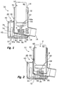
- Fig. 1 shows an inhalation device 10 according to the invention prior to their actuation.
- the inhalation device 10 has a housing 20, which is composed of two sub-housings 30, 40, which can be connected and disconnected without tools by means of a coupling device 18.
- the first partial housing 30 has approximately the shape of a conventional MDI. It surrounds an approximately L-shaped inhalation region 12, the upper end of which is designed to be open and forms an air inlet 14 and whose lower end is also open and forms a mouthpiece 16.
- the outer walls 32, 34 of this first part of housing 30 are stationary with the exception of a sensor wall portion 34 to each other and to the walls of the second housing part 40 and form the main portion 32 of the housing part 30.
- the said sensor wall portion 34 which at the lower end of the first housing part 30th is provided, is movable relative to this main portion 32 of the first sub-housing 30, this being achieved in that the sensor wall portion 34 by means of a circumferential thin-walled and leporelloartig corrugated connection portion 36 is integrally connected to the main portion 32. This allows a relative displacement of the sensor wall portion 34 in the direction of the arrow 2.
- the sensor wall portion 34 has a flat edge portion 34a which is flush with the surrounding bottom portions 32a of the main portion 32 to which it is integrally connected. In the middle of the sensor wall portion 34, this is thickened, wherein in this thickening a cylindrical receiving recess 34b and extending therefrom channel 34c are provided, which opens into a nozzle opening 34d.
- a container unit 60 is inserted.
- This has a medium container 62 and an outlet port 64 with an outlet opening 64a.
- the outlet nozzle can be displaced against a counterforce to the medium container 62.
- the outlet port 64 is inserted into the receiving recess 34b of the sensor wall section 34.
- the outlet nozzle 64 and the receiving recess 34b may be adapted to each other in such a way that they form a non-positive clamping connection.
- the upper end of the medium container 62 protrudes upward through the air inlet 14 out of the first sub-housing 30, the protruding part being provided for operating the inhalation device 10.
- the second sub-housing 40 comprises all electronic components of the inhalation device 10, these being shown only schematically in the figures.
- the electronic components comprise a base board 70, on which an integrated circuit 72, an energy store in the form of a battery 74 and an LCD display 76 are provided.
- the LCD display 76 is positioned so that it can be read through a recess 42 in the wall of the second part of housing 40 therethrough.
- the second partial housing 40 In the region of the sensor wall section 34, the second partial housing 40 has an opening 44. Below this opening 44, a button 78 is arranged on the base board 70.
- the said electronic components 70, 72, 74, 76 are adapted to detect and count operations of the button 78, the result of this count being displayed on the display 76. They thus serve together to count the successful discharge operations.
- the mode of operation is the following: To use the inhalation device, the mouthpiece 16 is intended to be enclosed by the lips of the user and air to be sucked in. At the same time, the medium container 62 is pushed down manually in relation to the main section 32 of the first part housing 30 in the direction of the arrow 4. As in Fig. 2 is shown, this leads on the one hand to the fact that the outlet port 64 is pressed against the medium container 62. In addition, with simultaneous elastic deflection of the connecting portion 36 and the sensor wall portion 34 of the first part of the housing 30 is pushed down, wherein it penetrates through the recess 44 of the second part of housing 40 in this and thereby comes into contact with the button 78.
- the continued displacement of the medium container 62 thus causes approximately an actuating signal from the button 78 is sent to the integrated circuit 72 and the medium discharge begins in the course of which medium along the arrow 6 from the medium container 62 into the inhalation region 12 passes where it mixes with the user drawn in air flowing along the arrows 8, and is sucked in through the mouthpiece 16 by the user.
- the discharge operation due to the operation of the operation button 78 is detected by the integrated circuit 72 and reproduced on the LCD display 76. It can be provided both that on the LCD display 76 remaining in the container doses are displayed or the already removed doses are displayed.
- the sub-housings 30, 40 can be decoupled from each other and a new first sub-housing 30 with a new container unit 60 to the reusable second sub-housing 40 with the electronics 70, 72, 74, 76, 78 are coupled ,
- the opening 44 of the second housing part 40 may also be formed by a membrane or a wall section formed in a manner similar to the sensor wall section 34a be closed, so that the isolated second housing part 40 is hermetically sealed to the outside.
Description
- Die Erfindung betrifft eine Inhalationsvorrichtung zur oralen Verabreichung eines pharmazeutischen Mediums. Eine solche gattungsgemäße Inhalationsvorrichtung weist ein Gehäuse mit einem Mundstück, eine in einem Inhalationsbereich des Gehäuses aufgenommene Containereinheit mit einem Mediumcontainer und einem zum Zwecke eines Austragvorgangs gegenüber dem Mediumcontainer verlagerbaren Auslassstutzen mit Auslassöffnung sowie einen Austragsensor zur Erfassung des Mediumaustrags auf.
- Gattungsgemäße Inhalationsvorrichtungen werden üblicherweise als "MDI" ("Metered-Dose Inhaler") bzw. "pMDI" ("pressurized Metered-Dose Inhaler") bezeichnet. Sie dienen der Verabreichung von Medikamenten, die zum Zwecke der Behandlung von Atemwegserkrankungen in zerstäubter Form in die Lunge des Benutzers gelangen sollen. Sie weisen das genannte Gehäuse auf, in welches die genannte Containereinheit eingesetzt ist. Das Gehäuse verfügt über einen Lufteinlass, der es gestattet, durch den Inhalationsbereich des Gehäuses hindurch Luft zum Mundstück hin einzusaugen, wobei im Zuge dieses Einsaugens der Austragvorgang von Medium aus dem Mediumcontainer durch Verlagern des Mediumcontainers gegenüber dem Auslassstutzen bewirkt wird, so dass die eingesogene Luft mit dem zerstäubten Medium vermengt und eingeatmet wird und somit in die Lunge gelangen kann.
- Der Austrag von Medium aus dem Mediumcontainer wird durch die Relativverlagerung des Mediumcontainers gegenüber dem Auslassstutzen bewirkt. Im einfachsten Falle kann bei gattungsgemäßen Inhalationsvorrichtungen der Mediumcontainer hierzu ein Stück weit aus dem Lufteinlass des Gehäuses herausragen, so dass er unmittelbar manuell kraftbeaufschlagt werden kann, um gegenüber dem in eine korrespondierende Ausnehmung des Gehäuses eingesetzten Auslassstutzen verlagert zu werden.
- Gattungsgemäße Inhalationsvorrichtungen sind mit einem Austragsensor zur Erfassung des Austragvorgangs versehen, insbesondere zum Zwecke der Zählung der Austragvorgänge. Hierdurch ist es einem Benutzer möglich, die Zahl der noch im Mediumcontainer verbliebenen Dosen des Mediums zu erfassen und somit einschätzen zu können, wie lange das Medium im Mediumcontainer noch reicht.
- Aus dem Stand der Technik sind verschiedene Möglichkeiten zur Gestaltung des Austragsensors bekannt.
- Die
WO 1997/033640 A1 beschreibt einen Drucksensor, der an einem für den Medienaustrag vorgesehenen Kanal angeordnet ist und den Mediumaustrag dadurch erfassbar macht. Diese Gestaltung ist vergleichsweise komplex und teuer. - Aus der
WO 1991/006334 A1 ist eine Gestaltung bekannt, bei der eine mechanische Erfassung des Austragvorgangs dadurch erreicht wird, dass die Bewegung des Mediumcontainers im Inhalationsbereich des Gehäuses erfasst wird. Eine hiermit vergleichbare Lösung ist auch aus derWO 1996/000595 A1 bekannt. Auch dieWO 2005/009325 A2 enthält eine Vielzahl von Gestaltungen, die größtenteils ebenfalls vorsehen, dass im Inhalationsbereich des Gehäuses ein Taster angeordnet ist, der im Zuge der Verlagerung des Mediumcontainers im Inhalationsbereich aktiviert wird. Aus diesem Dokument ist es weiterhin auch bekannt, einen Taster an der Außenseite des Gehäuses vorzusehen, der im Zuge der manuellen Kraftbeaufschlagung des Mediumcontainers gegenüber dem Gehäuse unweigerlich manuell mitbetätigt wird. - Weiter im Zusammenhang mit der vorliegenden Erfindung relevante Dokument des Standes der Technik sind die
WO 2008/006527 A1 und dieWO 92/17231 A1 - Aus der
US 6,138,669 A ist eine Gestaltung eines MDI bekannt, bei der der Druck des austretenden Mediums genutzt wird, um einen Flächenabschnitt auszulenken, der mittelbar einen Sensor betätigt. - Die Gestaltungen mit einem Taster, der unmittelbar die Bewegung des Mediumcontainers im Inhalationsbereich erfasst, geht mit dem Nachteil einher, dass eine zuverlässige Erkennung des Mediumaustrags häufig nicht vollständig gewährleistet ist, da die Containereinheit hinsichtlich ihrer Position im Innenbereich des Gehäuses Toleranzen unterliegt, die ein Vorbeiführen des Mediumcontainers am Taster gestatten. Eine dadurch ausbleibende Erkennung eines Austragvorgangs wird grundsätzlich als kritischer als eine fälschlicherweise stattfindende Erkennung eines tatsächlich nicht stattfindenden Austragvorgangs angesehen. Weiterhin ist die Gefahr gegeben, dass der Taster aufgrund seiner unmittelbaren Anordnung im Inhalationsbereich aufgrund von Feuchtigkeit versagt und somit Austragvorgänge nicht zuverlässig erfasst werden.
- Aufgabe der Erfindung ist es, eine gattungsgemäße Inhalationsvorrichtung dahingehend weiterzubilden, dass diese zuverlässig die Austragvorgänge erfassen kann. Dabei soll insbesondere auch eine kostengünstige Gestaltung erreicht werden.
- Erfindungsgemäß wird dies durch eine Inhalationsvorrichtung nach Anspruch 1 erreicht.
- Erfindungsgemäß ist demnach vorgesehen, dass ein den Inhalationsbereich begrenzender und insbesondere gegenüber einer Umgebung oder einem Aufnahmeraum für elektronische Komponenten trennender Wandungsabschnitt, der Sensorwandungsabschnitt, der eine Aufnahmeausnehmung für den Auslassstutzen aufweist, gegenüber einem Hauptabschnitt des Gehäuses beweglich ist und bei der Verlagerung des Mediumcontainers innerhalb des Inhalationsbereichs bewegt wird. Diese Bewegung des Sensorwandungsabschnitts wird statt der unmittelbaren Erfassung der Bewegung des Mediumcontainers vom Austragsensor erfasst. Dabei ist der Sensorwandungsabschnitt mit dem Hauptabschnitt des Gehäuses einstückig verbunden.
- Eine erfindungsgemäße Inhalationsvorrichtung weist die Merkmale der oben beschriebenen gattungsgemäßen Inhalationsvorrichtungen auf. Sie verfügt vorzugsweise über eine Elektronik, die zur Auswertung der Signale des insbesondere als Taster ausgebildeten Austragsensors ausgebildet ist. Diese Elektronik umfasst vorzugsweise einen integrierten Schaltkreis, der insbesondere der Zählung der Austragsvorgänge dient. Weiterhin umfasst sie vorzugsweise eine Batterie als Energiespeicher sowie eine Ausgabeeinheit, insbesondere in Form eines Displays, dem die Zahl der bereits abgegebenen oder noch enthaltenen Dosen zu entnehmen ist.
- Der Hauptabschnitt des Gehäuses, demgegenüber der Sensorwandungsabschnitt beweglich ist, umfasst jene Teile der Außenfläche des Gehäuses, die bestimmungsgemäß dem Halten der Inhalationsvorrichtung dienen wie insbesondere einem zylindrischen Gehäuseabschnitt, der die Containereinheit umgibt, sowie alle hierzu ortsfesten Komponenten des Gehäuses, wie insbesondere auch das Mundstück. Der Sensorwandungsabschnitt ist gegenüber diesem Hauptabschnitt beweglich, wobei er derart an den Hauptabschnitt angebunden ist, dass er nach Beendigung eines Austragvorgangs und Wegfall der entsprechenden manuellen Kraftbeaufschlagung in eine Ausgangslage zurückkehrt. Der als Teil des Gehäuses ausgebildete Sensorwandungsabschnitt ist aus dem gleichen Material wie der Hauptabschnitt gefertigt, insbesondere aus Kunststoff, und er ist einstückig zumindest mit den ihn umgebenden Teilen des Hauptabschnitts des Gehäuses verbunden, wobei ein Verbindungsbereich zwischen dem Hauptabschnitt und dem Sensorwandungsabschnitt verformbar ausgebildet ist. Diese Einstückigkeit gestattet insbesondere eine einfache Herstellbarkeit, da im Zuge der Herstellung des Gehäuses der Sensorwandungsabschnitt unmittelbar vorgesehen werden kann. Des Weiteren ist durch diese Einstückigkeit auch die genannte selbsttätige Rückkehr des Sensorwandungsabschnitts in seine Ausgangsposition durch eine entsprechende elastische Gestaltung des Verbindungsbereichs einfach erreichbar. Weiterhin ist die Einstückigkeit auch in Hinblick auf eine gewünschte Flüssigkeitsdichtigkeit von Vorteil. Hierzu ist vorzugsweise weiterhin vorgesehen, dass der Verbindungsbereich den Sensorwandungsabschnitt umlaufend umgibt und dadurch den Sensorwandungsabschnitt flüssigkeitsdichtend mit dem Hauptabschnitt des Gehäuses verbindet. In einem solchen Fall ist der Verbindungsbereich vorzugsweise als Bereich mit gegenüber dem Sensorwandungsabschnitt und dem Hauptabschnitt deutlich verringerter Wandungsstärke ausgebildet. Er kann insbesondere eine leporelloartige Gestaltung aufweisen, um eine unproblematische Verformbarkeit zu gewährleisten. Neben der beschriebenen flüssigkeitsdichtenden Gestaltung mit umlaufenden Verbindungsbereich ist es jedoch auch möglich, die Anbindung des Sensorwandungsabschnitts an den Hauptabschnitt des Gehäuses über diskrete und insbesondere dünnwandige Materialbrücken zu gewährleisten.
- Der Austragsensor ist vorzugsweise auf der dem Inhalationsbereich abgewandten Seite des Sensorwandungsabschnitts vorgesehen. Er ist dadurch in einer geschützten Position angeordnet. So ist keine Gefahr gegeben, den Austragsensor beim Einsetzen der Containereinheit zu beschädigen. Insbesondere ist bei der oben beschriebenen flüssigkeitsdichtenden Gestaltung des Verbindungsbereichs auch gewährleistet, dass der dem Inhalationsbereich abgewandte Austragsensor nicht durch im Inhalationsbereich vorhandene Feuchtigkeit beeinträchtigt wird.
- Es ist vorgesehen, dass der Sensorwandungsabschnitt im Betrieb stets ortsfest zum Auslassstutzen der Containereinheit verbleibt. Zu diesem Zweck ist es erfindungsgemäß vorgesehen, dass der Sensorwandungsabschnitt eine Aufnahmeausnehmung für den Auslassstutzen aufweist und vorzugsweise eine über einen Kanal mit der Aufnahmeausnehmung verbundene Austragdüse aufweist. Diese Austragdüse mündet dabei in den Inhalationsbereich des Gehäuses und definiert den Bereich, in dem im Betrieb das Medium aus dem Mediumcontainer mit der vom Benutzer eingesogenen Luft vermengt wird. Bei einer solchen Gestaltung, bei der der Sensorwandungsabschnitt ortsfest zum Auslassstutzen verbleibt, ist der Sensorwandungsabschnitt bei üblicher Benutzungsausrichtung eines MDI unterhalb der Containereinheit angeordnet. Er wird dementsprechend beim Hinunterdrücken des Mediumcontainers gegenüber dem Hauptabschnitt des Gehäuses in gleicher Richtung, jedoch in verminderndem Maße, gegenüber dem Hauptabschnitt des Gehäuses verlagert. Eine solche Gestaltung hat sich als besonders zuverlässig erwiesen, da hierdurch ausgeschlossen ist, dass Toleranzen hinsichtlich der Position der Containereinheit im Gehäuse eine inkorrekte Zählung bewirken, sei es Nichtzählung einer tatsächlich stattfindenden Betätigung oder durch Zählung einer begonnenen, jedoch vorzeitig vor Beginn des Flüssigkeitsaustrag beendeten Betätigung.
- Der Austragsensor, der Sensorwandungsabschnitt und die Containereinheit sind vorzugsweise derart aufeinander abgestimmt und derart angeordnet, dass im Zuge einer Verlagerung der Containereinheit gegenüber dem Hauptabschnitt des Gehäuses der Sensorwandungsabschnitt den Austragsensor betätigt, sobald oder bevor der Austragvorgang aus dem Mediumcontainer beginnt.
- Dies bedeutet, dass die zur Auslenkung des Sensorwandungsabschnitts erforderliche Kraft, die ausreicht, um den Austragsensor mittels des Sensorwandungsabschnitts auszulösen, mit jener Kraft übereinstimmt oder kleiner als jene Kraft ist, die erforderlich ist, um den Auslassstutzen der Containereinheit gegenüber dem Mediumcontainer soweit zu verlagern, dass der Austragvorgang beginnt. Bei der oben genannten Gestaltung, bei der der elastisch gegenüber dem Gehäuse auslenkbare Sensorwandungsabschnitt im Betrieb stets ortsfest zum Auslassstutzen verbleibt, teilt sich eine Verlagerungsstrecke des Mediumcontainers gegenüber dem Hauptabschnitt des Gehäuses auf in eine Teilstrecke, um die der Mediumscontainer gegenüber dem Auslassstutzen und dem Sensorwandungsabschnitt verlagert wird und eine Teilstrecke, um die der Auslassstutzen und der Sensorwandungsabschnitt gegenüber dem Hauptabschnitt des Gehäuses verlagert werden. Durch eine entsprechende Abstimmung der Anbindung des Sensorwandungsabschnitts an den Hauptabschnitt auf die Kraft, die zur Verlagerung des Auslassstutzens gegenüber dem Mediumscontainer erforderlich ist, kann das genannte Verhalten erreicht werden.
- Diese Art der Abstimmung gewährleistet, dass auch ein unvollständiger Austragvorgang, beispielsweise aufgrund nicht ausreichender Verlagerung des Mediumcontainers gegenüber dem Hauptabschnitt des Gehäuses, vom Austragsensor registriert wird und somit bei einer Zählung der Austragvorgängen Berücksichtigung findet. Eine Abweichung der aufgrund der Zählung bestimmten Restmenge des Mediums im Mediumcontainer gegenüber der tatsächlich noch vorhandenen Menge des Mediums ist dadurch lediglich in der Form möglich, dass die noch im Mediumcontainer enthaltene Mediummenge unterschätzt wird. Hierdurch wird der Situation vorgebeugt, dass vermeintlich noch Medium in dem Mediumcontainer verbleibt, dieses tatsächlich jedoch nicht mehr vorhanden ist.
- Der Austragsensor, der vorzugsweise als Taster ausgebildet ist, kann insbesondere am Hauptabschnitt des Gehäuses vorgesehen sein und so angeordnet sein, dass eine gegenüber einer Basis des Tasters verlagerbare Tasterfläche im Zuge der Betätigung der Inhalationsvorrichtung durch den Sensorwandungsabschnitt niedergedrückt wird. Wie oben bereits erwähnt, ist der Austragsensor vorzugsweise auf der dem Inhalationsbereich abgewandten Seite des Sensorwandungsabschnitts angeordnet. Besonders vorteilhaft ist es, wenn das Gehäuse zwei Teilgehäuse aufweist, die mittels einer Kopplungseinrichtung aneinander ankoppelbar sind, wobei ein erstes Teilgehäuse den Inhalationsbereich umgibt und den Sensorwandungsabschnitt aufweist und wobei ein zweites Teilgehäuse den Austragsensor aufweist.
- Bei einer solchen Gestaltung kann das erste Teilgehäuse dafür vorgesehen sein, nach der Verwendung mit einer Containereinheit gemeinsam mit dieser entsorgt zu werden, während das zweite Teilgehäuse, welches den Austragsensor sowie vorzugsweise alle anderen elektronischen Komponenten der Inhalationsvorrichtung aufweist, wiederverwendet wird. In einem solchen Falle ist der Austragsensor am zweiten Teilgehäuse so angeordnet, dass eine Kraftbeaufschlagung von außen den Sensor auslösen kann, wobei dieses Kraftbeaufschlagung im gekoppelten Zustand der Teilgehäuse durch den entsprechend angeordneten Sensorwandungsabschnitt bewirkt wird.
- Bei einer Weiterbildung dieser Gestaltung mit zwei Teilgehäusen weist das zweite Teilgehäuse einen Sensor auf, der geeignet ist, den Kopplungszustand der beiden Teilgehäuse zu erfassen. Dies kann ein separater Sensor sein. Es kann jedoch auch der Austragsensor so ausgebildet sein, dass er in Abhängigkeit beispielsweise der Auslenkung seiner Tasterfläche zum einen den Kopplungszustand und zum anderen die Verlagerung des Sensorwandungsabschnitts erfassen kann.
- Vorzugsweise sind die elektronischen Komponenten, insbesondere der zur Zählung vorgesehene Schaltkreis, derart ausgebildet, dass eine Betätigung des zur Zählung vorgesehenen Sensors nur dann für die Zählung herangezogen wird, wenn die Teilgehäuse sich im gekoppelten Zustand befinden.
- Bei einer solchen Gestaltung mit zwei Teilgehäusen ist es bevorzugst, dass das zweite Teilgehäuse einen Innenbereich aufweist, der im Bereich des Austragsensors durch einen formveränderlichen oder verlagerbaren Wandungsabschnitt begrenzt ist. Dies gestattet es, die Elektronik vollständig zu kapseln. Der Austragsensor liegt in einem solchen Falle auch im entkoppelten Zustand der Teilgehäuse nicht ungeschützt an der Außenseite des zweiten Teilgehäuses, sondern ist durch diesen Wandungsabschnitt, beispielsweise durch eine dünnwandige Membran, geschützt.
- Weitere Aspekte und Vorteile der Erfindung ergeben sich außer aus den Ansprüchen auch aus der nachfolgenden Beschreibung eines bevorzugten Ausführungsbeispiels der Erfindung, welches nachfolgend anhand der Figuren erläutert wird. Dabei zeigen:
- Fig. 1
- eine erfindungsgemäße Inhalationsvorrichtung vor der Betätigung und
- Fig. 2
- die erfindungsgemäße Inhalationsvorrichtung während der Betätigung.
-
Fig. 1 zeigt eine erfindungsgemäße Inhalationsvorrichtung 10 vor deren Betätigung. - Die Inhalationsvorrichtung 10 verfügt über ein Gehäuse 20, welches sich aus zwei Teilgehäusen 30, 40 zusammensetzt, die mittels Kopplungseinrichtung 18 werkzeuglos verbindbar und trennbar sind.
- Das erste Teilgehäuse 30 weist in etwa die Form eines konventionellen MDI auf. Es umgibt einen etwa L-förmigen Inhalationsbereich 12, dessen oberes Ende offen gestaltet ist und ein Lufteinlass 14 bildet und dessen unteres Ende ebenfalls offen gestaltet ist und ein Mundstück 16 bildet. Die Außenwandungen 32, 34 dieses ersten Teilgehäuses 30 sind mit Ausnahme eines Sensorwandungsabschnitts 34 zueinander und zu den Wandungen des zweiten Teilgehäuses 40 im Betrieb ortsfest und bilden den Hauptabschnitt 32 des Teilgehäuses 30. Lediglich der genannte Sensorwandungsabschnitt 34, der am unteren Ende des ersten Teilgehäuses 30 vorgesehen ist, ist gegenüber diesem Hauptabschnitt 32 des ersten Teilgehäuses 30 beweglich, wobei dies dadurch erreicht wird, dass der Sensorwandungsabschnitt 34 mittels eines umlaufenden dünnwandigen und leporelloartig gewellten Verbindungsbereichs 36 mit dem Hauptabschnitt 32 einstückig verbunden ist. Dies gestattet eine Relativverlagerung des Sensorwandungsabschnitts 34 in Richtung des Pfeils 2.
- Der Sensorwandungsabschnitt 34 weist einen flachen Randbereich 34a auf, der mit den umgebenden Bodenabschnitten 32a des Hauptabschnitts 32, mit denen er einstückig verbunden ist, fluchtet. In der Mitte des Sensorwandungsabschnitts 34 ist dieser verdickt ausgebildet, wobei in dieser Verdickung eine zylindrische Aufnahmeausnehmung 34b und ein sich davon erstreckender Kanal 34c vorgesehen sind, der in einer Düsenöffnung 34d mündet.
- In den Inhalationsbereich 12 des ersten Teilgehäuses 30 ist eine Containereinheit 60 eingesetzt. Diese verfügt über einen Mediumcontainer 62 sowie einen Auslassstutzen 64 mit einer Auslassöffnung 64a. Zum Zwecke des Mediumsaustrags aus dem Mediumcontainer 62 kann der Auslassstutzen gegen eine Gegenkraft gegenüber dem Mediumcontainer 62 verlagert werden. Im in
Fig. 1 dargestellten Zustand, in dem die Containereinheit bereits in das erste Teilgehäuse 30 eingesetzt ist, ist der Auslassstutzen 64 in die Aufnahmeausnehmung 34b des Sensorwandungsabschnitts 34 eingesetzt. Hierbei können der Auslassstutzen 64 und die Aufnahmeausnehmung 34b derart aufeinander angepasst sein, dass sie eine kraftschlüssige Klemmverbindung eingehen. Das obere Ende des Mediumcontainers 62 ragt durch den Lufteinlass 14 hindurch nach oben aus dem ersten Teilgehäuse 30 heraus, wobei der herausragende Teil zur Betätigung der Inhalationsvorrichtung 10 vorgesehen ist. - Das zweite Teilgehäuse 40 umfasst alle elektronischen Komponenten der Inhalationsvorrichtung 10, wobei diese in den Figuren nur schematisch dargestellt sind. Die elektronischen Komponenten umfassen eine Basisplatine 70, auf der ein integrierter Schaltkreis 72, ein Energiespeicher in Form einer Batterie 74 sowie eine LCD-Anzeige 76 vorgesehen sind. Die LCD-Anzeige 76 ist dabei so positioniert, dass sie durch eine Ausnehmung 42 in der Wandung des zweiten Teilgehäuses 40 hindurch abgelesen werden kann. Im Bereich des Sensorwandungsabschnitts 34 weist das zweite Teilgehäuse 40 eine Durchbrechung 44 auf. Unterhalb dieser Durchbrechung 44 ist auf der Basisplatine 70 ein Taster 78 angeordnet.
- Die genannten elektronischen Komponenten 70, 72, 74, 76 sind dafür ausgebildet, Betätigungen des Tasters 78 zu erfassen und zu zählen, wobei das Ergebnis dieser Zählung auf dem Display 76 dargestellt wird. Sie dienen somit gemeinsam der Zählung der erfolgten Austragvorgänge.
- Die Funktionsweise ist dabei die Folgende: Zur Verwendung der Inhalationsvorrichtung wird bestimmungsgemäß das Mundstück 16 von den Lippen des Benutzers umschlossen und Luft angesogen. Gleichzeitig wird der Mediumcontainer 62 manuell gegenüber dem Hauptabschnitt 32 des ersten Teilgehäuses 30 in Richtung des Pfeils 4 hinabgedrückt. Wie in
Fig. 2 dargestellt ist, führt dies einerseits dazu, dass der Auslassstutzen 64 gegenüber dem Mediumcontainer 62 eingedrückt wird. Darüber hinaus wird bei gleichzeitiger elastischer Auslenkung des Verbindungsbereichs 36 auch der Sensorwandungsabschnitt 34 des ersten Teilgehäuses 30 hinabgedrückt, wobei er durch die Ausnehmung 44 des zweiten Teilgehäuses 40 in dieses eindringt und dabei in Kontakt mit dem Taster 78 gelangt. Die fortgesetzte Verlagerung des Mediumcontainers 62 bewirkt somit, dass in etwa gleichzeitig ein Betätigungssignal vom Taster 78 an den integrierten Schaltkreis 72 gesendet wird und der Mediumaustrag beginnt, im Zuge dessen Medium entlang des Pfeils 6 aus dem Mediumcontainer 62 in den Inhalationsbereich 12 gelangt, wo es sich mit der vom Benutzer eingesogenen Luft, die entlang der Pfeile 8 strömt, vermengt und durch das Mundstück 16 vom Benutzer eingesogen wird. - Wie bereits beschrieben, wird der Austragvorgang aufgrund der Betätigung des Betätigungstasters 78 vom integrierten Schaltkreis 72 erfasst und auf der LCD-Anzeige 76 wiedergegeben. Dabei kann sowohl vorgesehen sein, dass auf der LCD-Anzeige 76 die noch im Container verbleibenden Dosen dargestellt werden oder aber die bereits entnommenen Dosen dargestellt werden.
- Sobald alle Dosen im Mediumcontainer 62 verbraucht sind, können die Teilgehäuse 30, 40 voneinander entkoppelt werden und ein neues erstes Teilgehäuse 30 mit einer neuen Containereinheit 60 an das wieder verwendbare zweite Teilgehäuse 40 mit der Elektronik 70, 72, 74, 76, 78 angekoppelt werden.
- Bei einer nicht dargestellten Weiterbildung kann die Öffnung 44 des zweiten Teilgehäuses 40 auch durch eine Membran oder einen in ähnlicher Weise wie der Sensorwandungsabschnitt 34a ausgebildeten Wandungsabschnitt verschlossen sein, so dass auch das isolierte zweite Teilgehäuse 40 nach außen hermetisch abgeschlossen ist.
Claims (8)
- Inhalationsvorrichtung (10) zur oralen Verabreichung eines pharmazeutischen Mediums mit- einem Gehäuse (20) mit einem Mundstück (16),- einer in einem Inhalationsbereich (12) des Gehäuses (20) aufgenommenen Containereinheit (60) mit- einem Mediumcontainer (62) und- einem zum Zwecke eines Austragvorgangs gegenüber dem Mediumcontainer (62) verlagerbaren Auslassstutzen (64) mit Auslassöffnung (64a),
und- einem Austragssensor (78) zur Erfassung des Austragvorgangs,
dadurch gekennzeichnet, dass- das Gehäuse (20) einen Hauptabschnitt (32) und einen gegenüber dem Hauptabschnitt (32) verlagerbaren Sensorwandungsabschnitt (34) aufweist,- der mit dem Hauptabschnitt (32) des Gehäuses (20) einstückig verbunden ist, wobei ein Verbindungsbereich (36) zwischen dem Hauptabschnitt (32) und dem Sensorwandungsabschnitt (34) verformbar ausgebildet ist, und- der im Betrieb stets ortsfest zum Auslassstutzen (64) verbleibt und hierfür eine Aufnahmeausnehmung (34b) für den Auslassstutzen (64) aufweist,
so dass der Sensorwandungsabschnitt (34) während eines Austragvorgangs gegenüber dem Hauptabschnitt (32) verlagert wird,- der Austragssensor (78) zur Erfassung der Verlagerung des Sensorwandungsabschnitts (34) gegenüber dem Hauptabschnitt (32) des Gehäuses (20) ausgebildet ist. - Inhalationsvorrichtung nach Anspruch 1,
dadurch gekennzeichnet, dass
der Verbindungsbereich (36) den Sensorwandungsabschnitt (34) umlaufend umgibt und dadurch den Sensorwandungsabschnitt (34) flüssigkeitsdichtend mit dem Hauptabschnitt (32) des Gehäuses (20) verbindet. - Inhalationsvorrichtung nach einem der vorstehenden Ansprüche,
dadurch gekennzeichnet, dass
der Austragssensor (78) auf der dem Inhalationsbereich (12) abgewandten Seite des Sensorwandungsabschnitts (34) vorgesehen ist. - Inhalationsvorrichtung nach einem der vorstehenden Ansprüche,
dadurch gekennzeichnet, dass
der Sensorwandungsabschnitt (34) einerseits und der Auslassstutzen (64) andererseits zueinander ortsfest vorgesehen sind. - Inhalationsvorrichtung nach einem der vorstehenden Ansprüche,
dadurch gekennzeichnet, dass
der Sensorwandungsabschnitt (34) eine über einen Kanal (34c) mit der Aufnahmeausnehmung (34b) verbundene Austragdüse (34d) aufweist. - Inhalationsvorrichtung nach einem der vorstehenden Ansprüche,
dadurch gekennzeichnet, dass
der Austragssensor (78), der Sensorwandungsabschnitt (34) und die Containereinheit (60) derart aufeinander abgestimmt und angeordnet sind, dass im Zuge einer Verlagerung der Containereinheit (60) gegenüber dem Hauptabschnitt (32) des Gehäuses (20) der Sensorwandungsabschnitt (34) den Austragssensor (78) betätigt, sobald oder bevor der Austragvorgang beginnt. - Inhalationsvorrichtung nach einem der vorstehenden Ansprüche, dadurch gekennzeichnet, dass
das Gehäuse (20) zwei Teilgehäuse (30, 40) aufweist, die mittels einer Kopplungseinrichtung (18) aneinander ankoppelbar sind, wobei- ein erstes Teilgehäuse (30) den Inhalationsbereich (12) umgibt und den Sensorwandungsabschnitt (34) aufweist und- ein zweites Teilgehäuse (40) den Austragssensor (78) aufweist. - Inhalationsvorrichtung nach Anspruch 7,
dadurch gekennzeichnet, dass
das zweite Teilgehäuse einen Innenbereich aufweist, der im Bereich des Austragssensors durch einen formveränderlichen oder verlagerbaren Wandungsabschnitt begrenzt ist.
Applications Claiming Priority (1)
| Application Number | Priority Date | Filing Date | Title |
|---|---|---|---|
| DE102010024912A DE102010024912B4 (de) | 2010-06-15 | 2010-06-15 | Inhalationsvorrichtung |
Publications (2)
| Publication Number | Publication Date |
|---|---|
| EP2397178A1 EP2397178A1 (de) | 2011-12-21 |
| EP2397178B1 true EP2397178B1 (de) | 2013-11-27 |
Family
ID=44118150
Family Applications (1)
| Application Number | Title | Priority Date | Filing Date |
|---|---|---|---|
| EP11168488.2A Active EP2397178B1 (de) | 2010-06-15 | 2011-06-01 | Inhalationsvorrichtung |
Country Status (4)
| Country | Link |
|---|---|
| US (1) | US8746238B2 (de) |
| EP (1) | EP2397178B1 (de) |
| JP (1) | JP5749090B2 (de) |
| DE (1) | DE102010024912B4 (de) |
Cited By (1)
| Publication number | Priority date | Publication date | Assignee | Title |
|---|---|---|---|---|
| CN106456910A (zh) * | 2014-04-02 | 2017-02-22 | 阿普塔尔拉多尔夫策尔有限责任公司 | 具有探测机构的制药的分配器 |
Families Citing this family (11)
| Publication number | Priority date | Publication date | Assignee | Title |
|---|---|---|---|---|
| DE102013214601B3 (de) * | 2013-07-25 | 2014-05-22 | Aptar Radolfzell Gmbh | Gehäuse für eine Inhalationsvorrichtung und Inhalationsvorrichtung zur oralen Verabreichung eines pharmazeutischen Mediums |
| CN115155686A (zh) | 2015-05-01 | 2022-10-11 | 雅培制药有限公司 | 用于去除容器的液体内含物的设备 |
| JP6818008B2 (ja) | 2015-07-20 | 2021-01-20 | パール セラピューティクス,インコーポレイテッド | エアロゾル送達システムおよび関連する方法 |
| EP3432955B1 (de) | 2016-03-24 | 2021-01-27 | Trudell Medical International | Beatmungssystem mit elektronischem indikator |
| EP3458132B1 (de) | 2016-05-19 | 2021-06-30 | Trudell Medical International | Intelligente giesskammer mit ventil |
| EP3481476B1 (de) | 2016-07-08 | 2021-09-08 | Trudell Medical International | Intelligente schwingende vorrichtung für positiven exspiratorischen druck |
| US11344685B2 (en) | 2016-11-18 | 2022-05-31 | Norton (Waterford) Limited | Drug delivery device with electronics |
| US11497867B2 (en) | 2016-12-09 | 2022-11-15 | Trudell Medical International | Smart nebulizer |
| WO2019135191A1 (en) | 2018-01-04 | 2019-07-11 | Trudell Medical International | Smart oscillating positive expiratory pressure device |
| US11395890B2 (en) | 2018-06-04 | 2022-07-26 | Trudell Medical International | Smart valved holding chamber |
| AU2020338979A1 (en) | 2019-08-27 | 2022-03-17 | Trudell Medical International Inc. | Smart oscillating positive expiratory pressure device |
Citations (1)
| Publication number | Priority date | Publication date | Assignee | Title |
|---|---|---|---|---|
| US6138669A (en) * | 1996-03-14 | 2000-10-31 | Oneida Research Services, Inc. | Dosage counter for metered dose inhaler (MDI) systems using a miniature pressure sensor |
Family Cites Families (19)
| Publication number | Priority date | Publication date | Assignee | Title |
|---|---|---|---|---|
| GB1413285A (en) * | 1971-11-25 | 1975-11-12 | Bespak Industries Ltd | Aerosol devices |
| US4509515A (en) * | 1982-02-23 | 1985-04-09 | Fisons Plc | Inhalation device |
| GB8924823D0 (en) | 1989-11-03 | 1989-12-20 | Smith Kline French Lab | Dosage inhalers |
| GB9020555D0 (en) * | 1990-09-20 | 1990-10-31 | Bespak Plc | Dispensing apparatus |
| WO1992017231A1 (en) * | 1991-03-28 | 1992-10-15 | Innomed, Inc. | Microelectronic inhaler having a counter and timer |
| JPH06275764A (ja) | 1993-03-19 | 1994-09-30 | Fujitsu Miyagi Electron:Kk | リードフレーム及びそのリードフレームを用いた半導体装置の製造方法 |
| DE4422710C1 (de) | 1994-06-29 | 1995-09-14 | Boehringer Ingelheim Kg | Inhalationsgerät mit einem Elektronikmodul zur Funktionsüberwachung |
| US6390088B1 (en) | 1993-12-13 | 2002-05-21 | Boehringer Ingelheim Kg | Aerosol inhaler |
| US5544647A (en) * | 1994-11-29 | 1996-08-13 | Iep Group, Inc. | Metered dose inhalator |
| US6029659A (en) * | 1995-04-17 | 2000-02-29 | Solar Shield Corporation | Inhalation device with counter |
| US5758638A (en) * | 1995-07-24 | 1998-06-02 | Kreamer; Jeffry W. | Indicator for a medicament inhaler |
| US5724986A (en) * | 1995-11-06 | 1998-03-10 | Jones Medical Instrument Co. | Casing and spirometer for metered dose inhaler |
| NZ504021A (en) * | 1997-10-17 | 2003-04-29 | Systemic Pulmonary Delivery Lt | Method and apparatus for delivering aerosolized medication having air discharged through air tube directly into plume of aerosolized medication |
| GB2344535B (en) * | 1998-12-11 | 2000-10-18 | Bespak Plc | Inhalation apparatus |
| US20050028815A1 (en) | 2003-07-23 | 2005-02-10 | Deaton Daniel M. | Apparatus for electronic dosage counter |
| GB2398065A (en) * | 2003-10-16 | 2004-08-11 | Bespak Plc | Dispensing apparatus |
| WO2007103712A2 (en) * | 2006-03-03 | 2007-09-13 | 3M Innovative Properties Company | Method and apparatus for metered dosed dispensing |
| DE102006032293A1 (de) * | 2006-07-11 | 2008-01-24 | Friedrich Sanner Gmbh & Co. Kg | Vorrichtung zur dosierten Abgabe von versprühbaren Stoffen |
| GB2470188B (en) * | 2009-05-11 | 2011-06-22 | Consort Medical Plc | Improvements in or relating to dispensing apparatus and dose counters |
-
2010
- 2010-06-15 DE DE102010024912A patent/DE102010024912B4/de not_active Expired - Fee Related
-
2011
- 2011-06-01 EP EP11168488.2A patent/EP2397178B1/de active Active
- 2011-06-10 US US13/134,611 patent/US8746238B2/en active Active
- 2011-06-14 JP JP2011132173A patent/JP5749090B2/ja active Active
Patent Citations (1)
| Publication number | Priority date | Publication date | Assignee | Title |
|---|---|---|---|---|
| US6138669A (en) * | 1996-03-14 | 2000-10-31 | Oneida Research Services, Inc. | Dosage counter for metered dose inhaler (MDI) systems using a miniature pressure sensor |
Cited By (2)
| Publication number | Priority date | Publication date | Assignee | Title |
|---|---|---|---|---|
| CN106456910A (zh) * | 2014-04-02 | 2017-02-22 | 阿普塔尔拉多尔夫策尔有限责任公司 | 具有探测机构的制药的分配器 |
| CN106456910B (zh) * | 2014-04-02 | 2019-09-13 | 阿普塔尔拉多尔夫策尔有限责任公司 | 具有探测机构的制药的分配器 |
Also Published As
| Publication number | Publication date |
|---|---|
| EP2397178A1 (de) | 2011-12-21 |
| JP2012000461A (ja) | 2012-01-05 |
| DE102010024912A1 (de) | 2011-12-15 |
| DE102010024912B4 (de) | 2013-02-28 |
| US8746238B2 (en) | 2014-06-10 |
| US20110303221A1 (en) | 2011-12-15 |
| JP5749090B2 (ja) | 2015-07-15 |
Similar Documents
| Publication | Publication Date | Title |
|---|---|---|
| EP2397178B1 (de) | Inhalationsvorrichtung | |
| EP2760517B1 (de) | Verbindungssystem für atemluftbefeuchter | |
| DE69831739T2 (de) | Spender mit zähleinrichtung der dosiseinheiten | |
| DE69832679T2 (de) | Vorrichtung zur Verabreichung von einem Arzneimittel in Aerosolform | |
| EP2195259B1 (de) | Sprühdose mit ausgaberohr | |
| DE102013214601B3 (de) | Gehäuse für eine Inhalationsvorrichtung und Inhalationsvorrichtung zur oralen Verabreichung eines pharmazeutischen Mediums | |
| EP2252351B1 (de) | Verabreichungsvorrichtung mit halteeinrichtung | |
| DE102009010565B3 (de) | Austragvorrichtung | |
| EP2037992B1 (de) | Vorrichtung zur dosierten abgabe von versprühbaren stoffen | |
| EP2496276A1 (de) | Drainagepumpeinheit | |
| EP3125978B1 (de) | Pharmazeutischer spender mit einer erfassungseinrichtung | |
| EP1620155A1 (de) | Vernebleranschlussvorrichtung für beatmungsgeräte oder dergleichen | |
| EP1905471A2 (de) | Inhalationsvorrichtung | |
| EP2125534A1 (de) | Behälter, insbesondere hermetisch verschlossene ampulle | |
| EP3701987B1 (de) | Pharmazeutischer spender, insbesondere inhalator | |
| EP3682972B1 (de) | Spender zum austrag von flüssigkeit, insbesondere zum austrag einer pharmazeutischen flüssigkeit, sowie set umfassend einen solchen spender | |
| EP0694314A1 (de) | Inhalationsvernebler mit Behältereinsatz für das Zerstäubungsgut | |
| EP2427241A1 (de) | Filtervorrichtung zur verwendung bei einem tracheostoma | |
| EP3096818B1 (de) | Verfahren und vorrichtung zur kontrolle des durchflusses durch eine medizinische infusionsleitung | |
| DE202018002848U1 (de) | Elektronischer Inhalator | |
| EP3275492A1 (de) | Flüssigkeitsspender, insbesondere inhalator | |
| WO2022008353A1 (de) | Oralspender für flüssigkeiten, insbesondere für nikotin- oder cannabishaltige flüssigkeiten | |
| DE202013012846U1 (de) | Elektronische Rauchvorrichtung | |
| DE202023107087U1 (de) | Vorrichtung zur subkutanen Verabreichung eines Medikaments | |
| DE202021105564U1 (de) | Vorrichtung zum Einbringen von Aromastoffen in Filter von Rauchartikeln |
Legal Events
| Date | Code | Title | Description |
|---|---|---|---|
| AK | Designated contracting states |
Kind code of ref document: A1 Designated state(s): AL AT BE BG CH CY CZ DE DK EE ES FI FR GB GR HR HU IE IS IT LI LT LU LV MC MK MT NL NO PL PT RO RS SE SI SK SM TR |
|
| AX | Request for extension of the european patent |
Extension state: BA ME |
|
| PUAI | Public reference made under article 153(3) epc to a published international application that has entered the european phase |
Free format text: ORIGINAL CODE: 0009012 |
|
| 17P | Request for examination filed |
Effective date: 20120117 |
|
| 17Q | First examination report despatched |
Effective date: 20120614 |
|
| RAP1 | Party data changed (applicant data changed or rights of an application transferred) |
Owner name: APTAR RADOLFZELL GMBH |
|
| GRAP | Despatch of communication of intention to grant a patent |
Free format text: ORIGINAL CODE: EPIDOSNIGR1 |
|
| INTG | Intention to grant announced |
Effective date: 20130617 |
|
| GRAS | Grant fee paid |
Free format text: ORIGINAL CODE: EPIDOSNIGR3 |
|
| GRAA | (expected) grant |
Free format text: ORIGINAL CODE: 0009210 |
|
| AK | Designated contracting states |
Kind code of ref document: B1 Designated state(s): AL AT BE BG CH CY CZ DE DK EE ES FI FR GB GR HR HU IE IS IT LI LT LU LV MC MK MT NL NO PL PT RO RS SE SI SK SM TR |
|
| REG | Reference to a national code |
Ref country code: GB Ref legal event code: FG4D Free format text: NOT ENGLISH |
|
| REG | Reference to a national code |
Ref country code: CH Ref legal event code: EP |
|
| REG | Reference to a national code |
Ref country code: CH Ref legal event code: NV Representative=s name: DR. LUSUARDI AG, CH |
|
| REG | Reference to a national code |
Ref country code: AT Ref legal event code: REF Ref document number: 642424 Country of ref document: AT Kind code of ref document: T Effective date: 20131215 |
|
| REG | Reference to a national code |
Ref country code: IE Ref legal event code: FG4D Free format text: LANGUAGE OF EP DOCUMENT: GERMAN |
|
| REG | Reference to a national code |
Ref country code: DE Ref legal event code: R096 Ref document number: 502011001701 Country of ref document: DE Effective date: 20140123 |
|
| REG | Reference to a national code |
Ref country code: NL Ref legal event code: VDEP Effective date: 20131127 |
|
| REG | Reference to a national code |
Ref country code: LT Ref legal event code: MG4D |
|
| PG25 | Lapsed in a contracting state [announced via postgrant information from national office to epo] |
Ref country code: NL Free format text: LAPSE BECAUSE OF FAILURE TO SUBMIT A TRANSLATION OF THE DESCRIPTION OR TO PAY THE FEE WITHIN THE PRESCRIBED TIME-LIMIT Effective date: 20131127 Ref country code: FI Free format text: LAPSE BECAUSE OF FAILURE TO SUBMIT A TRANSLATION OF THE DESCRIPTION OR TO PAY THE FEE WITHIN THE PRESCRIBED TIME-LIMIT Effective date: 20131127 Ref country code: HR Free format text: LAPSE BECAUSE OF FAILURE TO SUBMIT A TRANSLATION OF THE DESCRIPTION OR TO PAY THE FEE WITHIN THE PRESCRIBED TIME-LIMIT Effective date: 20131127 Ref country code: SE Free format text: LAPSE BECAUSE OF FAILURE TO SUBMIT A TRANSLATION OF THE DESCRIPTION OR TO PAY THE FEE WITHIN THE PRESCRIBED TIME-LIMIT Effective date: 20131127 Ref country code: LT Free format text: LAPSE BECAUSE OF FAILURE TO SUBMIT A TRANSLATION OF THE DESCRIPTION OR TO PAY THE FEE WITHIN THE PRESCRIBED TIME-LIMIT Effective date: 20131127 Ref country code: NO Free format text: LAPSE BECAUSE OF FAILURE TO SUBMIT A TRANSLATION OF THE DESCRIPTION OR TO PAY THE FEE WITHIN THE PRESCRIBED TIME-LIMIT Effective date: 20140227 Ref country code: IS Free format text: LAPSE BECAUSE OF FAILURE TO SUBMIT A TRANSLATION OF THE DESCRIPTION OR TO PAY THE FEE WITHIN THE PRESCRIBED TIME-LIMIT Effective date: 20140327 |
|
| PG25 | Lapsed in a contracting state [announced via postgrant information from national office to epo] |
Ref country code: LV Free format text: LAPSE BECAUSE OF FAILURE TO SUBMIT A TRANSLATION OF THE DESCRIPTION OR TO PAY THE FEE WITHIN THE PRESCRIBED TIME-LIMIT Effective date: 20131127 Ref country code: RS Free format text: LAPSE BECAUSE OF FAILURE TO SUBMIT A TRANSLATION OF THE DESCRIPTION OR TO PAY THE FEE WITHIN THE PRESCRIBED TIME-LIMIT Effective date: 20131127 Ref country code: CY Free format text: LAPSE BECAUSE OF FAILURE TO SUBMIT A TRANSLATION OF THE DESCRIPTION OR TO PAY THE FEE WITHIN THE PRESCRIBED TIME-LIMIT Effective date: 20131127 Ref country code: ES Free format text: LAPSE BECAUSE OF FAILURE TO SUBMIT A TRANSLATION OF THE DESCRIPTION OR TO PAY THE FEE WITHIN THE PRESCRIBED TIME-LIMIT Effective date: 20131127 |
|
| PG25 | Lapsed in a contracting state [announced via postgrant information from national office to epo] |
Ref country code: PT Free format text: LAPSE BECAUSE OF FAILURE TO SUBMIT A TRANSLATION OF THE DESCRIPTION OR TO PAY THE FEE WITHIN THE PRESCRIBED TIME-LIMIT Effective date: 20140327 |
|
| PG25 | Lapsed in a contracting state [announced via postgrant information from national office to epo] |
Ref country code: EE Free format text: LAPSE BECAUSE OF FAILURE TO SUBMIT A TRANSLATION OF THE DESCRIPTION OR TO PAY THE FEE WITHIN THE PRESCRIBED TIME-LIMIT Effective date: 20131127 |
|
| REG | Reference to a national code |
Ref country code: DE Ref legal event code: R097 Ref document number: 502011001701 Country of ref document: DE |
|
| PG25 | Lapsed in a contracting state [announced via postgrant information from national office to epo] |
Ref country code: CZ Free format text: LAPSE BECAUSE OF FAILURE TO SUBMIT A TRANSLATION OF THE DESCRIPTION OR TO PAY THE FEE WITHIN THE PRESCRIBED TIME-LIMIT Effective date: 20131127 Ref country code: SK Free format text: LAPSE BECAUSE OF FAILURE TO SUBMIT A TRANSLATION OF THE DESCRIPTION OR TO PAY THE FEE WITHIN THE PRESCRIBED TIME-LIMIT Effective date: 20131127 Ref country code: RO Free format text: LAPSE BECAUSE OF FAILURE TO SUBMIT A TRANSLATION OF THE DESCRIPTION OR TO PAY THE FEE WITHIN THE PRESCRIBED TIME-LIMIT Effective date: 20131127 Ref country code: PL Free format text: LAPSE BECAUSE OF FAILURE TO SUBMIT A TRANSLATION OF THE DESCRIPTION OR TO PAY THE FEE WITHIN THE PRESCRIBED TIME-LIMIT Effective date: 20131127 |
|
| PGFP | Annual fee paid to national office [announced via postgrant information from national office to epo] |
Ref country code: CH Payment date: 20140620 Year of fee payment: 4 |
|
| PG25 | Lapsed in a contracting state [announced via postgrant information from national office to epo] |
Ref country code: DK Free format text: LAPSE BECAUSE OF FAILURE TO SUBMIT A TRANSLATION OF THE DESCRIPTION OR TO PAY THE FEE WITHIN THE PRESCRIBED TIME-LIMIT Effective date: 20131127 |
|
| PLBE | No opposition filed within time limit |
Free format text: ORIGINAL CODE: 0009261 |
|
| STAA | Information on the status of an ep patent application or granted ep patent |
Free format text: STATUS: NO OPPOSITION FILED WITHIN TIME LIMIT |
|
| 26N | No opposition filed |
Effective date: 20140828 |
|
| REG | Reference to a national code |
Ref country code: DE Ref legal event code: R097 Ref document number: 502011001701 Country of ref document: DE Effective date: 20140828 |
|
| PG25 | Lapsed in a contracting state [announced via postgrant information from national office to epo] |
Ref country code: LU Free format text: LAPSE BECAUSE OF FAILURE TO SUBMIT A TRANSLATION OF THE DESCRIPTION OR TO PAY THE FEE WITHIN THE PRESCRIBED TIME-LIMIT Effective date: 20140601 Ref country code: MC Free format text: LAPSE BECAUSE OF FAILURE TO SUBMIT A TRANSLATION OF THE DESCRIPTION OR TO PAY THE FEE WITHIN THE PRESCRIBED TIME-LIMIT Effective date: 20131127 |
|
| PG25 | Lapsed in a contracting state [announced via postgrant information from national office to epo] |
Ref country code: SI Free format text: LAPSE BECAUSE OF FAILURE TO SUBMIT A TRANSLATION OF THE DESCRIPTION OR TO PAY THE FEE WITHIN THE PRESCRIBED TIME-LIMIT Effective date: 20131127 |
|
| REG | Reference to a national code |
Ref country code: IE Ref legal event code: MM4A |
|
| PG25 | Lapsed in a contracting state [announced via postgrant information from national office to epo] |
Ref country code: IE Free format text: LAPSE BECAUSE OF NON-PAYMENT OF DUE FEES Effective date: 20140601 |
|
| REG | Reference to a national code |
Ref country code: FR Ref legal event code: PLFP Year of fee payment: 5 |
|
| REG | Reference to a national code |
Ref country code: CH Ref legal event code: PL |
|
| REG | Reference to a national code |
Ref country code: DE Ref legal event code: R082 Ref document number: 502011001701 Country of ref document: DE Representative=s name: WITTE, WELLER & PARTNER PATENTANWAELTE MBB, DE Ref country code: DE Ref legal event code: R082 Ref document number: 502011001701 Country of ref document: DE Representative=s name: PATENTANWALTSKANZLEI CARTAGENA PARTNERSCHAFTSG, DE |
|
| PG25 | Lapsed in a contracting state [announced via postgrant information from national office to epo] |
Ref country code: MT Free format text: LAPSE BECAUSE OF FAILURE TO SUBMIT A TRANSLATION OF THE DESCRIPTION OR TO PAY THE FEE WITHIN THE PRESCRIBED TIME-LIMIT Effective date: 20131127 |
|
| PG25 | Lapsed in a contracting state [announced via postgrant information from national office to epo] |
Ref country code: LI Free format text: LAPSE BECAUSE OF NON-PAYMENT OF DUE FEES Effective date: 20150630 Ref country code: SM Free format text: LAPSE BECAUSE OF FAILURE TO SUBMIT A TRANSLATION OF THE DESCRIPTION OR TO PAY THE FEE WITHIN THE PRESCRIBED TIME-LIMIT Effective date: 20131127 Ref country code: CH Free format text: LAPSE BECAUSE OF NON-PAYMENT OF DUE FEES Effective date: 20150630 |
|
| REG | Reference to a national code |
Ref country code: FR Ref legal event code: PLFP Year of fee payment: 6 |
|
| PG25 | Lapsed in a contracting state [announced via postgrant information from national office to epo] |
Ref country code: BG Free format text: LAPSE BECAUSE OF FAILURE TO SUBMIT A TRANSLATION OF THE DESCRIPTION OR TO PAY THE FEE WITHIN THE PRESCRIBED TIME-LIMIT Effective date: 20131127 Ref country code: GR Free format text: LAPSE BECAUSE OF FAILURE TO SUBMIT A TRANSLATION OF THE DESCRIPTION OR TO PAY THE FEE WITHIN THE PRESCRIBED TIME-LIMIT Effective date: 20140228 |
|
| PG25 | Lapsed in a contracting state [announced via postgrant information from national office to epo] |
Ref country code: HU Free format text: LAPSE BECAUSE OF FAILURE TO SUBMIT A TRANSLATION OF THE DESCRIPTION OR TO PAY THE FEE WITHIN THE PRESCRIBED TIME-LIMIT; INVALID AB INITIO Effective date: 20110601 Ref country code: TR Free format text: LAPSE BECAUSE OF FAILURE TO SUBMIT A TRANSLATION OF THE DESCRIPTION OR TO PAY THE FEE WITHIN THE PRESCRIBED TIME-LIMIT Effective date: 20131127 Ref country code: BE Free format text: LAPSE BECAUSE OF FAILURE TO SUBMIT A TRANSLATION OF THE DESCRIPTION OR TO PAY THE FEE WITHIN THE PRESCRIBED TIME-LIMIT Effective date: 20140630 |
|
| REG | Reference to a national code |
Ref country code: FR Ref legal event code: PLFP Year of fee payment: 7 |
|
| REG | Reference to a national code |
Ref country code: AT Ref legal event code: MM01 Ref document number: 642424 Country of ref document: AT Kind code of ref document: T Effective date: 20160601 |
|
| PG25 | Lapsed in a contracting state [announced via postgrant information from national office to epo] |
Ref country code: AT Free format text: LAPSE BECAUSE OF NON-PAYMENT OF DUE FEES Effective date: 20160601 |
|
| REG | Reference to a national code |
Ref country code: FR Ref legal event code: PLFP Year of fee payment: 8 |
|
| PG25 | Lapsed in a contracting state [announced via postgrant information from national office to epo] |
Ref country code: MK Free format text: LAPSE BECAUSE OF FAILURE TO SUBMIT A TRANSLATION OF THE DESCRIPTION OR TO PAY THE FEE WITHIN THE PRESCRIBED TIME-LIMIT Effective date: 20131127 |
|
| PG25 | Lapsed in a contracting state [announced via postgrant information from national office to epo] |
Ref country code: AL Free format text: LAPSE BECAUSE OF FAILURE TO SUBMIT A TRANSLATION OF THE DESCRIPTION OR TO PAY THE FEE WITHIN THE PRESCRIBED TIME-LIMIT Effective date: 20131127 |
|
| REG | Reference to a national code |
Ref country code: DE Ref legal event code: R082 Ref document number: 502011001701 Country of ref document: DE Representative=s name: WITTE, WELLER & PARTNER PATENTANWAELTE MBB, DE |
|
| P01 | Opt-out of the competence of the unified patent court (upc) registered |
Effective date: 20230510 |
|
| PGFP | Annual fee paid to national office [announced via postgrant information from national office to epo] |
Ref country code: FR Payment date: 20230621 Year of fee payment: 13 Ref country code: DE Payment date: 20230623 Year of fee payment: 13 |
|
| PGFP | Annual fee paid to national office [announced via postgrant information from national office to epo] |
Ref country code: IT Payment date: 20230630 Year of fee payment: 13 Ref country code: GB Payment date: 20230622 Year of fee payment: 13 |