EP2395784A1 - Vorrichtung zur kanalschätzung, verfahren zur kanalschätzung, basisstation und kommunikationssystem - Google Patents
Vorrichtung zur kanalschätzung, verfahren zur kanalschätzung, basisstation und kommunikationssystem Download PDFInfo
- Publication number
- EP2395784A1 EP2395784A1 EP09839648A EP09839648A EP2395784A1 EP 2395784 A1 EP2395784 A1 EP 2395784A1 EP 09839648 A EP09839648 A EP 09839648A EP 09839648 A EP09839648 A EP 09839648A EP 2395784 A1 EP2395784 A1 EP 2395784A1
- Authority
- EP
- European Patent Office
- Prior art keywords
- reference signal
- allocated
- channel resource
- group
- signal
- Prior art date
- Legal status (The legal status is an assumption and is not a legal conclusion. Google has not performed a legal analysis and makes no representation as to the accuracy of the status listed.)
- Granted
Links
Images


Classifications
-
- H—ELECTRICITY
- H04—ELECTRIC COMMUNICATION TECHNIQUE
- H04L—TRANSMISSION OF DIGITAL INFORMATION, e.g. TELEGRAPHIC COMMUNICATION
- H04L25/00—Baseband systems
- H04L25/02—Details ; arrangements for supplying electrical power along data transmission lines
- H04L25/0202—Channel estimation
- H04L25/0224—Channel estimation using sounding signals
- H04L25/0228—Channel estimation using sounding signals with direct estimation from sounding signals
- H04L25/023—Channel estimation using sounding signals with direct estimation from sounding signals with extension to other symbols
-
- H—ELECTRICITY
- H04—ELECTRIC COMMUNICATION TECHNIQUE
- H04L—TRANSMISSION OF DIGITAL INFORMATION, e.g. TELEGRAPHIC COMMUNICATION
- H04L25/00—Baseband systems
- H04L25/02—Details ; arrangements for supplying electrical power along data transmission lines
- H04L25/0202—Channel estimation
-
- H—ELECTRICITY
- H04—ELECTRIC COMMUNICATION TECHNIQUE
- H04L—TRANSMISSION OF DIGITAL INFORMATION, e.g. TELEGRAPHIC COMMUNICATION
- H04L5/00—Arrangements affording multiple use of the transmission path
- H04L5/0001—Arrangements for dividing the transmission path
- H04L5/0003—Two-dimensional division
- H04L5/0005—Time-frequency
- H04L5/0007—Time-frequency the frequencies being orthogonal, e.g. OFDM(A) or DMT
-
- H—ELECTRICITY
- H04—ELECTRIC COMMUNICATION TECHNIQUE
- H04L—TRANSMISSION OF DIGITAL INFORMATION, e.g. TELEGRAPHIC COMMUNICATION
- H04L5/00—Arrangements affording multiple use of the transmission path
- H04L5/003—Arrangements for allocating sub-channels of the transmission path
- H04L5/0048—Allocation of pilot signals, i.e. of signals known to the receiver
-
- H—ELECTRICITY
- H04—ELECTRIC COMMUNICATION TECHNIQUE
- H04W—WIRELESS COMMUNICATION NETWORKS
- H04W88/00—Devices specially adapted for wireless communication networks, e.g. terminals, base stations or access point devices
- H04W88/08—Access point devices
Definitions
- the present invention relates to a channel estimating apparatus, a channel estimating method, a base station, and a communication system that perform channel estimation.
- orthogonal frequency division multiplexing (OFDM) systems such as long term evolution (LTE) systems
- RS reference signals
- LTE long term evolution
- RS shared links
- a wireless relay system uses a wireless relay apparatus to relay a wireless signal from a first wireless station and transmit the wireless signal to a second wireless station.
- the wireless relay apparatus includes a phase correction amount determining unit that based on channel information related to the transmission path between the first wireless station, the second wireless station, and the wireless relay apparatus, determines the amount of phase correction for the relayed signal; and a phase correcting unit that corrects the phase of the relayed signal, based on the phase correction amount determined by the phase correction amount determining unit (see, for example, Patent Document 1).
- An object of one aspect of the present invention is to perform accurate channel estimation.
- a further object of yet another aspect of the present invention is to improve channel resource utilization efficiency.
- a channel estimating apparatus in a first proposal, includes a receiver that receives reference signal groups that are respectively transmitted from wireless communications units and that each include a reference signal that is allocated a common channel resource allocated to a reference signal in another reference signal group among the reference signal groups; a first estimating unit that based on a reference signal that is in a first reference signal group among the reference signal groups received by the receiver and that is allocated a unique channel resource not allocated to a reference signal in another reference signal group, estimates a reference signal that is in the first reference signal group and allocated the common channel resource; and a second estimating unit that based on the reference signal estimated by the first estimating unit, estimates a reference signal that is in a second reference signal group among the received reference signal groups and that is allocated the common channel resource.
- the first estimating unit estimates a reference signal in the first reference signal group and allocated the common channel resource, the first reference signal group having a relatively high strength among the reference signal groups received by the receiver, and the second estimating unit estimates a reference signal in the second reference signal group and allocated the common channel resource, the second reference signal group having a relatively low strength among the received reference signal groups.
- the second estimating unit based on a reference signal that is in the second reference signal group and allocated a unique channel resource, further estimates the reference signal that was estimated based on the reference signal estimated by the first estimating unit.
- the first estimating unit based on the reference signal estimated by the second estimating unit, further estimates the reference signal that is in the first reference signal group and allocated the common channel resource.
- a channel estimating method includes receiving reference signal groups that are respectively transmitted from wireless communications units and that each include a reference signal that is allocated a common channel resource allocated to a reference signal in another reference signal group among the reference signal groups; estimating, based on a reference signal that is in a first reference signal group among the reference signal groups received at the receiving and that is allocated a unique channel resource not allocated to a reference signal in another reference signal group, a reference signal that is in the first reference signal group and allocated the common channel resource; and estimating, based on the estimated reference signal, a reference signal that is in a second reference signal group among the received reference signal groups and that is allocated the common channel resource.
- a base station that includes a wireless communications unit that transmits to a terminal apparatus, a first reference signal group that includes a reference signal that is allocated a common channel resource allocated to a reference signal in a second reference signal group transmitted to the terminal apparatus from another base station.
- the wireless communications unit allocates to a reference signal in the first reference signal group, a unique channel resource that is not allocated to a reference signal in the second signal group, where the allocated unique channel source is orthogonal to the channel resource of a reference signal that is in the first reference signal group and allocated a unique channel resource.
- the wireless communications unit alternately allocates a subcarrier to each reference signal that is allocated a unique channel resource, the allocated subcarriers being orthogonal to one another.
- the wireless communications unit allocates a sub-frame head slot to each reference signal that is allocated a unique channel resource that is not allocated to a reference signal in the second signal group.
- a base station that includes a first wireless communications unit that transmits a first reference signal group to a terminal apparatus; and a second wireless communications unit that transmits to the terminal apparatus, a second reference signal group that includes a reference signal that is allocated a common channel resource allocated to a reference signal in the first reference signal group.
- a communications system includes multiple base stations that respectively transmit a reference signal group that includes a reference signal that is allocated a common channel resource allocated to a reference signal in another reference signal group; and a channel estimating apparatus that based on a reference signal that is in a first reference signal group among the reference signal groups transmitted by the base stations and that is allocated a unique channel resource not allocated to a reference signal in another reference signal group, estimates a reference signal that is in the first reference signal group and allocated the common channel resource, and based on the estimated reference signal, further estimates a reference signal that is in a second reference signal group among the transmitted reference signal groups and that is allocated the common channel resource.
- a communication system in a sixth proposal, includes a base station that includes wireless communications units that respectively transmit a reference signal group that includes a reference signal that is allocated a common channel resource allocated to reference signal in another reference signal group; and a channel estimating apparatus that based on a reference signal that is in a first reference signal group among the reference signal groups transmitted by the wireless communications units and that is allocated a unique channel resource not allocated to a reference signal in another reference signal group, estimates a reference signal that is in the first reference signal group and allocated the common channel resource, and based on the estimated reference signal, further estimates a reference signal that is in a second reference signal group among the transmitted reference signal groups and that is allocated the common channel resource.
- a channel estimating method includes transmitting reference signal groups that each includes a reference signal that is allocated a common channel resource allocated to a reference signal in another transmitted reference signal group; receiving the transmitted reference signal groups; estimating, based on a reference signal that is in a first reference signal group among the transmitted reference signal groups and that is allocated a unique channel resource not allocated to a reference signal in another reference signal group, a reference signal that is in the first reference signal group and allocated the common channel resource; and estimating, based on the estimated reference signal, a reference signal that is in a second reference signal group among the transmitted reference signal groups and that is allocated the common channel resource.
- FIG. 1 is a block diagram of a communication system according to an embodiment.
- a communication system 100 according to the embodiment includes a base station 110, a base station 120, and a channel estimating apparatus 130.
- reference numeral 101 in FIG. 1 an example will be described where 4 channel resources CR1 to CR4 depicted in a grid pattern are allocated to various types of signals that are transmitted from the base station 110 and the base station 120.
- the base station 110 wirelessly transmits a reference signal group 111 to the channel estimating apparatus 130.
- Channel resource CR1 and channel resource CR4 are allocated to reference signal RS0 in the reference signal group 111.
- the base station 120 wirelessly transmits a reference signal group 121 to the channel estimating apparatus 130.
- Channel resource CR3 and channel resource CR4 are allocated to reference signal RS1 in the reference signal group 121.
- the reference signal group 111 and the reference signal group 121 include reference signals that have been allocated the same channel resource.
- channel resource CR4 is allocated to reference signal RS0 in the reference signal group 111 and to reference signal RS1 in the reference signal group 121.
- channel resource CR1 is allocated to reference signal RS0 in the reference signal group 111, but not to reference signal RS1 in the reference signal group 121.
- channel resource CR3 is allocated to reference signal RS1 in the reference signal group 121, but not to reference signal RS0 in the reference signal group 111.
- Channel resource CR2 is allocated to neither reference signal RS0 nor reference signal RS1.
- channel resource CR4 is allocated to multiple reference signals, while channel resources CR1 to CR3 are not allocated to multiple reference signals.
- the channel estimating apparatus 130 includes a receiver 131, a first estimating unit 132, and a second estimating unit 133.
- the receiver 131 simultaneously receives the reference signal group 111 and the reference signal group 121 transmitted from the base station 110 and the base station 120.
- a reference signal group 140 depicts the state of the reference signals received by the receiver 131.
- the receiver 131 outputs to the first estimating unit 132, the reference signal group 111 wirelessly transmitted from the base station 110. For example, the receiver 131 extracts from the received reference signal group 140, the respective reference signals at channel resource CR1 and channel resource CR4, which the base station 110 allocated reference signal RS0, and outputs the extracted reference signals to the first estimating unit 132.
- the reference signal group 140 received by the receiver 131 also includes at channel resource CR4, reference signal RS1, which is wirelesssly transmitted from the base station 120. Consequently, the reference signal group 111 output from the receiver 131 to the first estimating unit 132 includes reference signal RS0 and reference signal RS1 at channel resource CR4.
- the receiver 131 outputs to the second estimating unit 133, the reference signal group 121 wirelessly transmitted from the base station 120. For example, the receiver 131 extracts from the received reference signal group 140, the respective reference signals at channel resource CR3 and channel resource CR4, which the base station 120 allocated reference signal RS1, and outputs the extracted reference signals to the second estimating unit 133.
- the reference signal group 140 received by the receiver 131 also includes at channel resource CR4, reference signal RS0, which is wirelessly transmitted from the base station 110. Consequently, the reference signal group 121 output from the receiver 131 to the second estimating unit 133 includes reference signal RS0 and reference signal RS1 at channel resource CR4.
- the receiver 131 may output to the first estimating unit 132, the stronger reference signal group among the reference signal group 111 and the reference signal group 121 and may output to the second estimating unit 133, the weaker reference signal group.
- the strength of the reference signal group 111 is greater than that of the reference signal group 121.
- the receiver 131 outputs the reference signal group 111 to the first estimating unit 132 and outputs the reference signal group 121 to the second estimating unit 133.
- the first estimating unit 132 estimates a reference signal that is in the reference signal group 111 output from the receiver 131 and allocated a common channel resource that is also allocated to a reference signal in the reference signal group 121.
- the first estimating unit 132 makes the estimation based on a reference signal that is in the reference signal group 111 and allocated a unique channel resource that is not allocated to a reference signal in the reference signal group 121.
- the first estimating unit 132 estimates reference signal RS0 that is in the reference signal group 111 and allocated channel resource CR4.
- the first estimating unit 132 makes the estimation based on reference signal RS0 that is allocated channel resource CR1.
- the first estimating unit 132 uses channel resource CR4 of the reference signal group 111 from the receiver 131 for the estimated reference signal RS0, outputs the reference signal group 111 downstream.
- the first estimating unit 132 further outputs the estimated reference signal RS0 to the second estimating unit 133.
- the second estimating unit 133 estimates a reference signal that is in the reference signal group 121 output from the receiver 131 and allocated a common channel resource that is also allocated to a reference signal in the reference signal group 111.
- the second estimating unit 133 makes the estimation based on the reference signal RS0 received from the first estimating unit 132.
- the second estimating unit 133 estimates reference signal RS1 in the reference signal group 121 and allocated channel resource CR4.
- the second estimating, unit 133 makes the estimation based on reference signal RS0 output from the first estimating unit 132.
- the second estimating unit 133 subtracts from the signals (including reference signal RS0 and reference signal RS1) of channel resource CR4 of the reference signal group 121, the reference signal RS0 output from the first estimating unit 132, whereby reference signal RS1 allocated channel resource CR4 of the reference signal group 121 is estimated.
- the second estimating unit 133 may estimate the reference signal further based on a reference signal that is in the reference signal group 121 and allocated a unique channel resource that is not allocated to a reference signal in the reference signal group 111. For example, based on reference signal RS1 allocated channel resource CR3, the second estimating unit 133 estimates reference signal RS1 allocated channel resource CR4 of the reference signal group 121.
- the second estimating unit 133 uses channel resource CR4 of the reference signal group 121 from the receiver 131, for the estimated reference signal RS1, and outputs the reference signal group 121 downstream. Further, the second estimating unit 133 may output the estimated reference signal RS1 to the first estimating unit 132. In this case, the first estimating unit 132 further estimates the estimated reference signal RS0, based on reference signal RS1 output from the second estimating unit 133 (see, for example FIGS. 4 and 5 ).
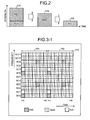
- FIG. 2 is a diagram depicting reference signal estimation for channel resource CR4 depicted in FIG. 1 .
- the horizontal axis represents time and the vertical axis represents signal strength at channel resource CR4 depicted in FIG. 1 .
- Signal 210 represents the signal at channel resource CR4 of the reference signal group 140 received by the receiver 131.
- signal 210 includes reference signal RS0 and reference signal RS1. Consequently, the strength of signal 210 is a sum of the respective strengths of reference signal RS0 and reference signal RS1. Further, the strength of reference signal RS0 is greater than that of reference signal RS1.
- Signal 220 represents the reference signal RS0 estimated by the first estimating unit 132.
- Signal 220 for example, is estimated based on reference signal RS0 at channel resource CR1.
- Signal 230 the represents reference signal RS1 estimated by the second estimating unit 133.
- Signal 230 is estimated by subtracting signal 220 from signal 210.
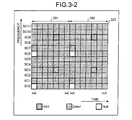
- FIG. 3-1 is a diagram depicting an example of reference signal design (part 1).
- FIG. 3-2 is a diagram depicting an example of reference signal design (part 2).
- Signal 310 depicted in FIG. 3-1 represents a signal transmitted from the base station 110.
- Signal 320 depicted in FIG. 3-2 represents a signal transmitted from the base station 120.
- Signal 310 and signal 320 are respectively allocated channel resources (resource elements) that are divided by a horizontal axis and vertical axis grids.
- the vertical grid depicts channel resource division by frequency.
- Each subcarrier SC0 to SC11 represents a subcarrier dividing signal 310 and signal 320 by frequency.
- Each channel resource for signal 310 is allocated to any one among reference signal RS0, a data signal Data0, a null signal Null transmitted by the base station 110.
- Each channel resource for signal 320 is allocated to any one among reference signal RS1, a data signal Data1, and a null signal (Null) transmitted by the base station 120.
- a null signal is a signal that conveys neither a reference signal nor a data signal, and that prevents reference signal interference.
- each subcarrier SC1 and SC7 is allocated to a null signal in signal 310 and to reference signal RS1 in signal 320, reference signals do not simultaneously use the slot.
- the reference signal group of signal 310 and the reference signal group of signal 320 each include a reference signal that uses the same channel resource.
- reference signals that are allocated a unique channel resource are allocated channel resources that are orthogonal to one another.
- reference signal RS0 is allocated subcarrier SC0
- reference signal RS1 is allocated subcarrier SC1, which is orthogonal to subcarrier SC0.
- reference signal RS0 is allocated subcarrier SC6
- reference signal RS1 is allocated subcarrier SC7, which is orthogonal to subcarrier SC6.
- reference signals that are allocated a unique channel resource are respectively allocated the head slot of a sub-frame.
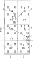
- FIG. 4 is a diagram depicting a detailed example of channel estimation by each estimating unit.
- reference numeral 410 represents estimation (by the first estimating unit 132) of the reference signal group 111 transmitted from the base station 110 (see FIG. 1 ).
- Reference numeral 420 represents estimation (by the second estimating unit 133) of the reference signal group 121 transmitted from the base station 120 (see FIG. 1 ).
- the reference signal group input to the first estimating unit 132 includes 4 reference signals RS0 and a signal that includes reference signal RS0 as well reference signal RS1 (reference numeral 411a).
- the reference signal group input to the second estimating unit 133 includes 4 reference signals RS1 and a signal that includes reference signal RS1 as well as reference signal RS0 (reference numeral 421a).
- the first estimating unit 132 applies Wiener filtering to the input reference signal group.
- Wiener filtering is used in reference signal estimation
- configuration is not limited to Wiener filtering and another type of circuit may be used (the same similarly applies hereinafter).
- Wiener filtering weight by applying a Wiener filtering weight, the strength of each reference signal in the reference signal group at the first estimating unit 132 is equalized and the noise (reference signal RS1) in the signal depicted by reference numeral 411a is reduced (reference numeral 412a).
- the resulting reference signal RS0 represented by reference numeral 412a is output to the second estimating unit 133.
- the second estimating unit 133 subtracts from the signal represented by reference numeral 421a, reference signal RS0 output from the first estimating unit 132 (reference numeral 412a). Consequently, in the reference signal group at the second estimating unit 133, the signal represented by reference numeral 421a, less the reference signal RS0 component, becomes reference signal RS1 (reference numeral 422a).
- the second estimating unit 133 applies Wiener filtering to the reference signal group that includes the resulting reference signal RS1 represented by reference numeral 422a. Consequently, as depicted by reference numeral 423, by applying a Weiner filtering weight, the strength of each reference signal in the reference signal group at the second estimating unit 133 is equalized and reference signal RS0 noise in reference signal RS1 represented by reference numeral 422a is reduced (reference numeral 423a).
- the reference signal represented by reference numeral 423a is output to the first estimating unit 132.
- the first estimating unit 132 subtracts from the signal represented by reference numeral 411a, reference signal RS1 (reference numeral 423a) output from the second estimating unit 133. Consequently, in the reference signal group at the first estimating unit 132, the signal represented by reference numeral 411a, less the reference signal RS1 component, becomes reference signal RS0 (reference numeral 413a).
- Reference signal RS1 represented by reference numeral 423a is an extremely accurate estimation of reference signal RS1 by the subtraction of reference signal RS0 represented by reference numeral 422 and the Wiener filtering represented by reference numeral 423. Consequently, noise (reference signal RS1 component) is removed with favorable accuracy from reference signal RS0 (reference numeral 413a) estimated based on reference signal RS1 represented by reference numeral 423a, as compared to reference signal RS0 represented by reference numeral 412a.
- Reference signal RS0 represented by reference numeral 414a is output to the second estimating unit 133 and the operation represented by reference numerals 422, 423, and 413 are repeatedly performed (two-dimensional iterative estimation). Consequently, the estimation accuracy of reference signal RS0 included in the signal represented by reference numeral 411a and reference signal RS1 included in the signal represented by reference numeral 421a can be gradually improved.
- the first estimating unit 132 and the second estimating unit 133 for example, perform the operations represented by reference numerals 422, 423, and 413, a fixed number of times.
- the first estimating unit 132 and the second estimating unit 133 may perform the operations represented by reference numerals 422, 423, and 413 until the accuracy of channel estimation improves.
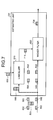
- FIG. 5 is a block diagram of a configuration for implementing the channel estimation depicted in FIG. 4 .
- a channel estimating apparatus 500 depicted in FIG. 5 is an example of a modification of the channel estimating apparatus 130 depicted in FIG. 1 .
- the receiver 510 receives the reference signal group transmitted from the base station 110 and the reference signal group transmitted from the base station 120.
- Reference signal 501 represents a reference signal that is in the reference signal group transmitted from the base station 110 and allocated a unique channel resource that is not allocated to a reference signal in the reference signal group transmitted from the base station 120.
- Reference signal 502 is a reference signal that is in the reference signal group transmitted from the base station 120 and allocated a unique channel resource that is not allocated to a reference signal in the reference signal group transmitted from the base station 110.
- Signal 503 is a signal that includes reference signals of each reference signal group transmitted from the base station 110 and the base station 120, the reference signals being allocated the same channel resource.
- the receiver 510 outputs each reference signal 501 and signal 503 to the estimating units 521, 522 to 52n, respectively. Further, the receiver 510 outputs each reference signal 502 and signal 503 to the estimating units 531, 532 to 53n, respectively.
- the estimating unit 521 applies Weiner filtering to reference signal 501 and signal 503 output from the receiver 510, and estimates the reference signal output from the base station 110 and included in signal 503.
- the estimating unit 521 outputs the estimated reference signal to the estimating unit 531.
- the estimating unit 531 subtracts from signal 503 output from the receiver 510, the reference signal output from the estimating unit 521 and estimates the reference signal output from the base station 120 and included in signal 503. Further, the estimating unit 531 applies Wiener filtering to each reference signal 502 output from the receiver 510 and to the estimated reference signal, and estimates the reference signal output from the base station 120. The estimating unit 531 outputs the estimated reference signal to the estimating unit 522.
- the estimating unit 522 subtracts from signal 503 output from the receiver 510, the reference signal output from the estimating unit 531 and estimates the reference signal output from the base station 110 and included in signal 503. Further, the estimating unit 522 applies Weiner filtering to each reference signal 501 output from the receiver 510 and to the estimated reference signal, and estimates the reference signal output from the base station 110. The estimating unit 522 outputs the estimated reference signal to the estimating unit 532.
- the estimating unit 532 subtracts from signal 503 output from the receiver 510, the reference signal output from the estimating unit 522 and estimates the reference signal output from the base station 120 and included in the signal 503. Further, the estimating unit 532 applies Wiener filtering to each reference signal 502 output from the receiver 510 and to the estimated reference signal, estimates the reference signal output from the base station 120, and outputs the estimated reference signal to the estimating unit 523 (not depicted).
- the estimating unit 52n subtracts from signal 503 output from the receiver 510, the reference signal output from the estimating unit 53(n-1) (not depicted) and estimates the reference signal output from the base station 110 and included in signal 503. Further, the estimating unit 52n applies Weiner filtering to each reference signal 501 output from the receiver 510 and to the estimated reference signal, and estimates the reference signal output from the base station 110.
- the estimating unit 52n outputs the estimated reference signal to the estimating unit 53n. Further, the estimating unit 52n outputs each Weiner filtered reference signal downstream. In this manner, subtraction and Weiner filtering using the reference signals output from the estimating units 531 to 53n are repeatedly performed by the estimating units 521 to 52n (the estimating unit 521 does not perform subtraction), whereby the reference signal output from the base station 110 is accurately estimated.
- the estimating unit 53n subtracts from signal 503 output from the receiver 510, the reference signal output from the estimating unit 52n and estimates the reference signal output from the base station 120 and included in signal 503. Further, the estimating unit 53n applies Weiner filtering to each reference signal 502 output from the receiver 510 and to the estimated reference signal, and outputs each Weiner filtered reference signal downstream.
- the reference signals output from the base station 110 and estimated by estimating units 521 to 52n, and the reference signals output from the base station 120 and estimated by the estimating units 531 to 53n are, for example, used in channel resource allocation for a terminal apparatus equipped with the channel estimating apparatus 500.
- FIG. 6 is a block diagram of a configuration of the estimating unit 521 depicted in FIG. 5 .
- the estimating unit 521 includes a canceller 610 and a Weiner filter 620.
- signal 503 is input to the canceller 610 and each reference signal 501 is input to the Weiner filter 620.
- An estimated reference signal is not input to the canceller 610 of the estimating unit 521 (0).
- the canceller 610 outputs signal 503 as is to the Weiner filter 620.
- the Weiner filter 620 filters each reference signal 501 input thereto and signal 503 output from the canceller 610.
- the Weiner filter 620 outputs to the estimating unit 531, reference signal 630 (output from the base station 110) estimated by Weiner filtering and included in signal 503.
- FIG. 7 is a block diagram of a configuration of the estimating unit 531 depicted in FIG. 5 .
- components identical to those depicted in FIG. 6 are given the same reference numerals used in FIG. 6 and description thereof is omitted.
- signal 503 is input to the canceller 610 and each reference signal 502 is input to the Weiner filter 620.
- Signal 503 and reference signal 630 output from the estimating unit 521 are input to the canceller 610.
- the canceller 610 cancels (subtracts) from signal 503 input thereto, reference signal 630 output from the estimating unit 521.
- the canceller 610 outputs to the Weiner filter 620, reference signal 710 obtained by the cancellation.
- the Weiner filter 620 filters each reference signal 502 input thereto and reference signal 710 output from the canceller 610.
- the Weiner filter 620 outputs to the estimating unit 522, reference signal 720 (output from the base station 120) estimated by Weiner filtering and included in signal 503.
- FIG. 8 is a block diagram of the estimating unit 522 depicted in FIG. 5 .
- components identical to those depicted in FIG. 6 are given the same reference numerals used in FIG. 6 and description thereof is omitted.
- signal 503 is input to the canceller 610 and each reference signal 501 is input to the Weiner filter 620.
- Signal 503 and reference signal 720 output from the estimating unit 531 are input to the canceller 610.
- the canceller 610 cancels (subtracts) from signal 503 input thereto, reference signal 720 output from the estimating unit 531.
- the canceller 610 outputs to the Weiner filter 620, reference signal 810 obtained by the cancellation.
- the Weiner filter 620 filters each reference signal 501 input thereto and reference signal 810 output from the canceller 610.
- the Weiner filter 620 outputs to the estimating unit 532, reference signal 820 (output from the base station 110) estimated by Weiner filtering and included in signal 503.
- the estimating unit 532 depicted in FIG. 5 is identical to the estimating unit 531 depicted in FIG. 7 and therefore, description thereof is omitted.
- signal 503 and reference signal 820 output from the estimating unit 522 are input to the canceller 610 of the estimating unit 532.
- the canceller 610 cancels from signal 503 input thereto, reference signal 820 output from the estimating unit 522.
- the Weiner filter 620 outputs to the estimating unit 523, the reference signal (output from the base station 120) estimated by Weiner filtering and included in signal 503.
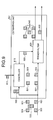
- FIG. 9 is a block diagram of a configuration of the estimating unit 52n depicted in FIG. 5 .
- components identical to those depicted in FIG. 6 are given the same reference numerals used in FIG. 6 and description thereof is omitted.
- signal 503 is input to the canceller 610 and each reference signal 501 is input to the Weiner filter 620.
- Signal 503 and reference signal 910 output from the estimating unit 53(n-1) are input to the canceller 610.
- the canceller 610 cancels from signal 503 input thereto, reference signal 910.
- the canceller 610 outputs to the Weiner filter 620, reference signal 920 obtained by the cancellation.
- the Weiner filter 620 filters each reference signal 501 input thereto and reference signal 920 output from the canceller 610.
- the Weiner filter 620 outputs to the estimating unit 53n, reference signal 930 (output from the base station 110) estimated by Weiner filtering and included in signal 503. Further, the Weiner filter 620 outputs downstream a Weiner-filtered reference signal group 940.
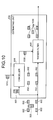
- FIG. 10 is a block diagram of a configuration of the estimating unit 53n depicted in FIG. 5 .
- components identical to those depicted in FIG. 6 are given the same reference numerals used in FIG. 6 and description thereof is omitted.
- signal 503 is input to the canceller 610 and each reference signal 502 is input to the Weiner filter 620.
- Signal 503 and reference signal 1010 output from the estimating unit 52n are input to the canceller 610.
- the canceller 610 cancels from signal 503 input thereto, reference signal 1010.
- the canceller 610 outputs to the Weiner filter 620, reference signal 1020 obtained by the cancellation.
- the Weiner filter 620 filters each reference signal 502 input thereto and reference signal 1020 output from the canceller 610.
- the Weiner filter 620 outputs downstream, a reference signal group 1030 estimated by Weiner filtering.
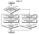
- FIG. 11 is a flowchart depicting an operation example of the channel estimating apparatus depicted in FIG. 5 .
- the channel estimating apparatus determines, at the receiver 510, whether the strength of reference signal RS0 (e.g., reference signal 501) received from the base station 110 is greater than the strength of reference signal RS1 (e.g., reference signal 502) received from the base station 120 (step S1101).
- RS0 e.g., reference signal 501
- RS1 e.g., reference signal 502
- step S1101 if the strength of reference signal RS0 is greater than that of reference signal RS1 (step S1101: YES), the receiver 510 outputs reference signal RS0 to the estimating unit 521 and outputs reference signal RS1 to the estimating unit 531.
- the estimating unit 521 estimates reference signal RS0 (step S1102).
- the estimating unit 531 estimates reference signal RS1 (step S1103).
- the channel estimating apparatus determines whether the reference signal estimations at steps S1102 and S1103 have been performed n-times (step S1104). If the reference signal estimations have not been performed n-times (step S1104: NO), the channel estimating apparatus returns to step S1102 and continues processing therefrom. If the reference signal estimations have been performed n-times (step S1104: YES), a series of the operations ends.
- step S1101 if the strength of reference signal RS0 is not greater than that of reference signal RS1 (step S1101: NO), the receiver 510 outputs reference signal RS1 to the estimating unit 521 and outputs reference signal RS0 to the estimating unit 531.
- the estimating unit 521 estimates reference signal RS1 (step S1105) and then, the estimating unit 531 estimates reference signal RS0 (step S1106) .
- the channel estimating apparatus determines whether the reference signal estimations at steps S1105 and S1106 have been performed n-times (step S1107). If the reference signal estimations have not been performed n-times (step S1107: NO), the channel estimating apparatus returns to step S1105 and continues processing therefrom. If the reference signal estimations have been performed n-times (step S1107: YES), a series of the operations ends.
- reference signal RS0 is subject to subtraction and Weiner filtering using reference signal RS1.
- reference signal RS1 is subject to subtraction and Weiner filtering using reference signal RS0. Consequently, reference signal RS0 and reference signal RS1 are accurately estimated.
- reference signal RS0 and reference signal RS1 are estimated n-times. Consequently, reference signal RS0 and reference signal RS1 can be repeatedly estimated until the estimation accuracy improves.
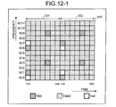
- FIG. 12-1 is a diagram depicting another example of reference signal design (part 1).
- FIG. 12-2 is a diagram depicting another example of reference signal design (part 2).
- FIGS. 12-1 and 12-2 descriptions of portions identical to those depicted in FIGS. 3-1 and 3-2 will be omitted.
- reference signals that are in the reference signal groups and respectively allocated unique channel resources are alternately allocated orthogonal subcarriers.
- reference signal RS0 is allocated subcarrier SC1 in the sub-frame 331; and in the sub-frame 332, reference signal RS0 is allocated subcarrier SC0, which is orthogonal to subcarrier SC1. Further, in the sub-frame 331, reference signal RS0 is allocated subcarrier SC6; and in the sub-frame 332, reference signal RS0 is allocated subcarrier SC7, which is orthogonal to subcarrier SC6.
- reference signal RS1 is allocated subcarrier SC0 in the sub-frame 331; and in the sub-frame 332, reference signal RS1 is allocated subcarrier SC1, which is orthogonal to subcarrier SC0. Further, in the sub-frame 331, reference signal RS1 is allocated subcarrier SC7; and in the sub-frame 332, reference signal RS1 is allocated subcarrier SC6, which is orthogonal to subcarrier SC7.
- reference signals that are allocated a unique channel resource are alternately allocated orthogonal subcarriers, whereby reference signal allocation according to frequency can be distributed, enabling the accuracy of channel estimation at each frequency to be improved.
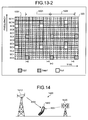
- FIG. 13-1 is a diagram depicting yet another example of reference signal design (part 1).
- FIG. 13-2 is a diagram depicting yet another example of reference signal design (part 2).
- FIGS. 13-1 and 13-2 descriptions of portions identical to those in FIGS. 3-1 and 3-2 will be omitted.
- reference signals allocated the same channel resource are allocated the head slot of a sub-frame.
- a range 1301 in FIGS. 13-1 and 13-2 represents a unit of the reference signal group subject to Weiner filtering.
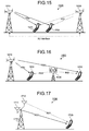
- FIG. 14 is a diagram depicting a first application example of the communication system.
- the communication system 100 depicted in FIG. 1 can be applied to a communication system 1400 depicted in FIG. 14 .
- the communication system 1400 includes a base station 1410, a base station 1420, and a terminal apparatus 1430 (user equipment (UE)).
- the base station 1410 and the base station 1420 both provide a wireless service to the terminal apparatus 1430.
- UE user equipment
- the base station 1410 includes a wireless communications unit that transmits to the terminal apparatus 1430, a first reference signal group that includes multiple reference signals RS0.
- the base station 1420 includes a wireless communications unit that transmits to the terminal apparatus 1430, a second reference signal group that includes multiple reference signals RS1. A portion of the reference signal channel resources for the first reference signal group and for the second reference signal group are the same.
- the terminal apparatus 1430 includes the channel estimating apparatus 130 depicted in FIG. 1 or the channel estimating apparatus 500 depicted in FIG. 5 .
- the terminal apparatus 1430 accurately estimates the received first reference signal group and second reference signal group.
- the terminal apparatus 1430 for example, based on the resulting estimation, selects a communication counterpart from among the base station 1410 and the base station 1420.
- FIG. 15 is a diagram depicting a second application example of the communication system.
- the communication system 100 depicted in FIG. 1 can be applied to a communication system 1500 depicted in FIG. 15 .
- the communication system 1500 is a coordinated multi-point (CoMP) system.
- the communication system 1500 includes a base station 1510, a base station 1520, a terminal apparatus 1531, and a terminal apparatus 1532.
- CoMP coordinated multi-point
- the base station 1510 is a Serving eNode-B and the base station 1520 is a Collaborative eNode-B.
- the terminal apparatus 1531 and the terminal apparatus 1532 can receive both reference signal RS0 transmitted from the base station 1510 and reference signal RS1 transmitted from the base station 1520.
- the terminal apparatuses 1531, 1532 respectively, include the channel estimating apparatus 130 depicted in FIG. 1 or the channel estimating apparatus 500 depicted in FIG. 5 .
- the terminal apparatuses 1531, 1532 respectively, accurately estimate the received first reference signal group and second reference signal group.
- the terminal apparatuses 1531, 1532 respectively for example, based on the resulting estimation, select a communication counterpart from among the base station 1510 and the base station 1520.
- FIG. 16 is a diagram depicting a third application of the communication system.
- the communication system 100 depicted in FIG. 1 can be applied to a communication system 1600 depicted in FIG. 16 .
- the communication system 1600 is a relay forwarding system that includes a base station 1610, a relay station 1620, a terminal apparatus 1631, and a terminal apparatus 1632.
- the terminal apparatus 1632 can select from among a direct, wireless communication path with the base station 1610 and a wireless communication path with the base station 1610, passing through the relay station 1620 and the terminal apparatus 1631.
- the terminal apparatus 1632 can receive both reference signal RS0 transmitted from the base station 1610 and reference signal RS1 transmitted from the relay station 1620.
- the terminal apparatus 1632 includes the channel estimating apparatus 130 depicted in FIG. 1 or the channel estimating apparatus 500 depicted in FIG. 5 .
- the terminal apparatus 1632 accurately estimates the received first reference signal group and second reference signal group.
- the terminal apparatus 1632 selects at least one among, the direct communication path with the base station 1610 and the communication passing through the relay station 1620 and the terminal apparatus 1631.
- FIG. 17 depicts a fourth application example of the communication system.
- the communication system 100 depicted in FIG. 1 can be applied to a communication system 1700 depicted in FIG. 17 .
- the communication system 1700 is a multiple input multiple output (MIMO) system that includes a base station 1710 and a terminal apparatus 1720.
- the base station 1710 includes a first wireless communications unit 1711 and a second wireless communications unit 1712.
- the base station 1710 can communicate with the terminal apparatus 1720 via both the first wireless communications unit 1711 and the second wireless communications unit 1712.
- the first wireless communications unit 1711 transmits to the terminal apparatus 1720, the first reference signal group that includes reference signal RS0.
- the second wireless communications unit 1712 transmits to the terminal apparatus 1720, the second reference signal group that includes reference signal RS1.
- a portion of the reference signal channel resources for the second reference signal group transmitted by the second wireless communications unit 1712 and a portion of the reference signal channel resources for the first reference signal group transmitted by the first wireless communications unit 1711 are the same.
- the first wireless communications unit 1711 has a configuration that corresponds to the base station 110 depicted in FIG. 1 ; and the first wireless communications unit 1711 has a configuration that corresponds to the base station 120 depicted in FIG. 1 .
- the terminal apparatus 1720 can receive both reference signal RS0 output from the first wireless communications unit 1711 and reference signal RS1 output from the second wireless communications unit 1712.
- the terminal apparatus 1720 includes the channel estimating apparatus 130 depicted in FIG. 1 or the channel estimating apparatus 500 depicted in FIG. 5 .
- the terminal apparatus 1720 accurately estimates the received first reference signal group and second reference signal group.
- the terminal apparatus 1720 selects a communication counterpart from among the first wireless communications unit 1711 and the terminal apparatus 1720.
- FIGS. 3-1 and 3-2 an example was described in which 4 reference signals respectively using unique channel resources surround reference signals in signal 310 and in signal 320 that use the same channel resource.
- the arrangement of the reference signals using unique channel resources is not limited hereto. Next, other examples of reference signal arrangement will be described.
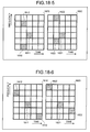
- FIG. 18-1 is a diagram depicting a first example of reference signal design modification.
- signal 1810 represents a signal transmitted from the base station 110.
- Signal 1820 represents a signal transmitted from the base station 120.
- signal 1810 and signal 1820 are respectively allocated channel resources that are divided by a horizontal axis and vertical axis grids.
- Reference signal 1811 represents a reference signal that is in the reference signal group included in signal 1810 and allocated a common channel resource also allocated to a reference signal in the reference signal group included in signal 1820.
- Reference signal 1812 represents a reference signal that is in the reference signal group included in signal 1810 and allocated a unique channel resource that is not allocated to a reference signal in the reference signal group included in signal 1820.
- Reference signal 1821 represents a reference signal that is in the reference signal group included in signal 1820 and allocated a common channel resource that is also allocated to a reference signal in the reference signal group included in signal 1810.
- Reference signal 1822 represents a reference signal that is in reference signal group included in signal 1820 and allocated a unique channel resource that is not allocated to a reference signal in the reference signal group included in signal 1810.
- reference signal 1811 is surrounded by 4 reference signals 1812.
- reference signal 1821 is surrounded by 4 reference signals 1822.
- reference signal 1811 is accurately estimated based on reference signal 1812.
- reference signal 1821 is accurately estimated based on reference signal 1822. Consequently, even if the number of times (for example, n in FIG. 5 or FIG. 11 ) that the estimation operation is performed is reduced, channel estimation can be accurately performed, enabling improved channel estimating speed.
- reference signal 1811 and reference signal 1821 are allocated the same channel resource, in signal 1810 and signal 1820, the number of channel resources used for allocation to reference signals can be reduced. For example, compared to a case where each reference signal is allocated a unique channel resource, the number of channel resources used for allocation to the reference signals can be cut by 1/4.
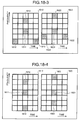
- FIG. 18-2 is a diagram depicting a second example of reference signal design modification.
- FIG. 18-3 is a diagram depicting a third example of reference signal design modification.
- reference signal 1810 in signal 1810, reference signal 1811 is surrounded by 3 reference signals 1812.
- reference signal 1821 in signal 1820, reference signal 1821 is surrounded by 3 reference signals 1822.
- the accuracy of reference signal estimation at Weiner filtering is improved.
- the number of channel resources used for allocation to reference signals can be reduced. For example, compared to a case where each reference signal is allocated a unique channel resource, the number of channel resources used for allocation to the reference signals can be reduced by 1/3.
- FIG. 18-4 is a diagram depicting a fourth example of reference signal design modification.
- FIG. 18-5 is a diagram depicting a fifth example of reference signal design modification.
- FIG. 18-6 is a diagram depicting a sixth example of reference signal design modification.
- 1 reference signal 1811 is surrounded by 2 reference signals 1812.
- 1 reference signal 1821 is surrounded by 2 reference signals 1822.
- the accuracy of reference signal estimation at Weiner filtering is improved.
- the number of channel resources used for allocation to reference signals can be reduced. For example, compared to a case each reference signal is allocated a unique channel resource, the number of channel resources used for allocation to the reference signals can be reduced by 1/2.
- improved channel estimation accuracy and improved efficiency of channel resource utilization can be facilitated by providing a method of accurately estimating each reference signal group having a portion of mutually common channel resources.
- reference signals that are allocated unique channel resources are used to estimate a reference signal that is allocated a channel resource also allocated to another reference signal.
- the estimated reference signal is used to estimate the other reference signal allocated the same channel resource.
- a reference signal that is allocated a common channel resource and is in the reference signal group having the higher strength among the reference signal groups is estimated first.
- the reference signal is estimated based on a reference signal that is allocated a unique channel resource, since the strength of the reference signal that that is allocated a unique channel resource is high, the accuracy of estimation can be further improved.
- a method of using a reference signal that is allocated a unique channel resource to estimate a reference signal that is allocated a common channel resource a method of using Weiner filtering was described.
- the method is not limited hereto. For example, by performing processing that equalizes the reference signal allocated a unique channel resource and the reference signal allocated a common channel resource, the latter reference signal can be estimated.
Landscapes
- Engineering & Computer Science (AREA)
- Signal Processing (AREA)
- Computer Networks & Wireless Communication (AREA)
- Power Engineering (AREA)
- Mobile Radio Communication Systems (AREA)
Applications Claiming Priority (1)
| Application Number | Priority Date | Filing Date | Title |
|---|---|---|---|
| PCT/JP2009/051974 WO2010089871A1 (ja) | 2009-02-05 | 2009-02-05 | チャネル推定装置、チャネル推定方法、基地局および通信システム |
Publications (3)
| Publication Number | Publication Date |
|---|---|
| EP2395784A1 true EP2395784A1 (de) | 2011-12-14 |
| EP2395784A4 EP2395784A4 (de) | 2015-03-11 |
| EP2395784B1 EP2395784B1 (de) | 2016-09-14 |
Family
ID=42541793
Family Applications (1)
| Application Number | Title | Priority Date | Filing Date |
|---|---|---|---|
| EP09839648.4A Not-in-force EP2395784B1 (de) | 2009-02-05 | 2009-02-05 | Kanaschätzung in kooperativen drahtlosen kommunikationssystemen |
Country Status (6)
| Country | Link |
|---|---|
| US (2) | US20110281608A1 (de) |
| EP (1) | EP2395784B1 (de) |
| JP (1) | JP5333462B2 (de) |
| KR (1) | KR101244533B1 (de) |
| CN (1) | CN102308617B (de) |
| WO (1) | WO2010089871A1 (de) |
Cited By (1)
| Publication number | Priority date | Publication date | Assignee | Title |
|---|---|---|---|---|
| WO2019088890A1 (en) * | 2017-11-06 | 2019-05-09 | Telefonaktiebolaget Lm Ericsson (Publ) | Channel estimation |
Families Citing this family (6)
| Publication number | Priority date | Publication date | Assignee | Title |
|---|---|---|---|---|
| US20110032838A1 (en) * | 2009-08-04 | 2011-02-10 | Qualcomm Incorporated | Mitigation of crs misalignment in coordinated multipoint communications |
| US8675560B2 (en) * | 2010-09-03 | 2014-03-18 | Qualcomm Incorporated | UE receiver reference signal processing that utilizes resource partitioning information |
| US20130242920A1 (en) * | 2011-08-01 | 2013-09-19 | Nec (China) Co., Ltd. | Method and apparatus for enhancing downlink harq |
| KR101679268B1 (ko) * | 2012-07-13 | 2016-11-24 | 노키아 솔루션스 앤드 네트웍스 게엠베하 운트 코. 카게 | 약한 채널 컴포넌트들의 추정 |
| KR102266595B1 (ko) * | 2014-05-02 | 2021-06-18 | 삼성전자주식회사 | 무선 통신 시스템에서 채널 추정 방법 및 장치 |
| CN111641571B (zh) * | 2020-05-13 | 2023-06-23 | Oppo广东移动通信有限公司 | 噪声估计方法及装置、终端、计算机可读存储介质 |
Family Cites Families (9)
| Publication number | Priority date | Publication date | Assignee | Title |
|---|---|---|---|---|
| FR2814011B1 (fr) | 2000-09-14 | 2003-10-24 | France Telecom | Procede d'estimation optimale d'un canal de propagation reposant uniquement sur les symboles pilotes et estimateur correspondant |
| JP4289854B2 (ja) | 2002-09-20 | 2009-07-01 | 京セラ株式会社 | 無線基地装置、移動端末装置、参照信号制御方法および参照信号制御プログラム |
| US7280467B2 (en) * | 2003-01-07 | 2007-10-09 | Qualcomm Incorporated | Pilot transmission schemes for wireless multi-carrier communication systems |
| JP4394474B2 (ja) | 2004-02-16 | 2010-01-06 | 株式会社エヌ・ティ・ティ・ドコモ | 無線中継システム、無線中継装置及び無線中継方法 |
| JP2006033083A (ja) | 2004-07-12 | 2006-02-02 | Oki Electric Ind Co Ltd | Ofdm伝送システム。 |
| IL169417A (en) * | 2005-06-27 | 2011-05-31 | Alvarion Ltd | Method and apparatus for improving signal reception in wireless networks subjected to interference caused by transmissions in neighboring cells |
| MX2009004495A (es) * | 2006-11-01 | 2009-05-13 | Qualcomm Inc | Diseño de señal de referencia para busqueda de celula en un sistema de comunicacion inalambrica ortogonal. |
| EP3823318B1 (de) * | 2007-04-11 | 2025-10-29 | Optis Wireless Technology, LLC | Information über referenzsignalstruktur für nachbarzellenmessungen |
| EP2297870B1 (de) * | 2008-06-18 | 2012-02-22 | Telefonaktiebolaget LM Ericsson (publ) | Verringerung von störungen zwischen zellen |
-
2009
- 2009-02-05 KR KR1020117015780A patent/KR101244533B1/ko not_active Expired - Fee Related
- 2009-02-05 EP EP09839648.4A patent/EP2395784B1/de not_active Not-in-force
- 2009-02-05 JP JP2010549311A patent/JP5333462B2/ja not_active Expired - Fee Related
- 2009-02-05 WO PCT/JP2009/051974 patent/WO2010089871A1/ja not_active Ceased
- 2009-02-05 CN CN200980156082.6A patent/CN102308617B/zh not_active Expired - Fee Related
-
2011
- 2011-08-02 US US13/196,004 patent/US20110281608A1/en not_active Abandoned
-
2013
- 2013-12-27 US US14/141,722 patent/US9407468B2/en not_active Expired - Fee Related
Non-Patent Citations (1)
| Title |
|---|
| See references of WO2010089871A1 * |
Cited By (2)
| Publication number | Priority date | Publication date | Assignee | Title |
|---|---|---|---|---|
| WO2019088890A1 (en) * | 2017-11-06 | 2019-05-09 | Telefonaktiebolaget Lm Ericsson (Publ) | Channel estimation |
| US11218341B2 (en) | 2017-11-06 | 2022-01-04 | Telefonaktiebolaget Lm Ericsson (Publ) | Channel estimation |
Also Published As
| Publication number | Publication date |
|---|---|
| JPWO2010089871A1 (ja) | 2012-08-09 |
| EP2395784A4 (de) | 2015-03-11 |
| JP5333462B2 (ja) | 2013-11-06 |
| CN102308617A (zh) | 2012-01-04 |
| CN102308617B (zh) | 2014-04-02 |
| WO2010089871A1 (ja) | 2010-08-12 |
| US20110281608A1 (en) | 2011-11-17 |
| US9407468B2 (en) | 2016-08-02 |
| EP2395784B1 (de) | 2016-09-14 |
| KR20110098796A (ko) | 2011-09-01 |
| US20140105171A1 (en) | 2014-04-17 |
| KR101244533B1 (ko) | 2013-03-18 |
Similar Documents
| Publication | Publication Date | Title |
|---|---|---|
| EP2395784B1 (de) | Kanaschätzung in kooperativen drahtlosen kommunikationssystemen | |
| CN103518339B (zh) | 接收装置、发送装置以及无线通信方法 | |
| CN107534626B (zh) | 全双工通信网络的信道脉冲响应估计 | |
| CN102986265B (zh) | 中继站、基站以及通信方法 | |
| CN101877689B (zh) | 数据发送处理方法与装置、数据接收处理方法与装置 | |
| US20140078972A1 (en) | Method and Apparatus for Signaling Demodulation Reference Signals | |
| JP6294834B2 (ja) | ユーザ装置、基地局、干渉低減方法、及び干渉低減制御情報通知方法 | |
| EP3152849A1 (de) | Verfahren und vorrichtung für mehrfachzugang in einem drahtloskommunikationssystem | |
| EP3285425B1 (de) | Verfahren und vorrichtung zur koordinierten mehrpunkte-übertragung mit adaptivem downlink | |
| CN104284361A (zh) | 一种干扰测量方法、网络侧设备及终端侧设备 | |
| WO2015082327A1 (en) | Method and apparatus for equalization processing in a wireless communication receiver | |
| WO2016209710A1 (en) | Data communication using interference alignment | |
| CN107113075A (zh) | 用于基于移动通信系统中的干扰测量来接收信号的方法和装置 | |
| CN104639476B (zh) | 抑制td‑lte交叉时隙干扰的方法和上行基站 | |
| CN102100045B (zh) | 数据发送处理方法与装置、数据接收处理方法与装置 | |
| US9119082B1 (en) | Reference signal design for interference measurement | |
| CN113196682A (zh) | 波束强度相关的ⅱ型信道状态信息系数反馈 | |
| CN101485121A (zh) | 干扰减小的方法和设备 | |
| CN105099606B (zh) | 一种控制信息传输方法和设备 | |
| EP2466775A1 (de) | Funkkommunikationssystem, funkkommunikationsvorrichtung und funkkommunikationsverfahren | |
| CN103067118A (zh) | 一种实现数据传输的方法及装置 | |
| CN108988918A (zh) | 数据传输方法及相关设备 | |
| KR101430611B1 (ko) | 다중 사용자 다중 입출력 시스템에서 데이터 전송 방법 및장치 | |
| KR20170117244A (ko) | 단말 간 협조 통신을 위한 방법, 장치 및 시스템 | |
| CN117769038A (zh) | 一种消除干扰的方法和相关设备 |
Legal Events
| Date | Code | Title | Description |
|---|---|---|---|
| PUAI | Public reference made under article 153(3) epc to a published international application that has entered the european phase |
Free format text: ORIGINAL CODE: 0009012 |
|
| 17P | Request for examination filed |
Effective date: 20110830 |
|
| AK | Designated contracting states |
Kind code of ref document: A1 Designated state(s): AT BE BG CH CY CZ DE DK EE ES FI FR GB GR HR HU IE IS IT LI LT LU LV MC MK MT NL NO PL PT RO SE SI SK TR |
|
| DAX | Request for extension of the european patent (deleted) | ||
| REG | Reference to a national code |
Ref country code: DE Ref legal event code: R079 Ref document number: 602009041201 Country of ref document: DE Free format text: PREVIOUS MAIN CLASS: H04W0024100000 Ipc: H04L0005000000 |
|
| A4 | Supplementary search report drawn up and despatched |
Effective date: 20150209 |
|
| RIC1 | Information provided on ipc code assigned before grant |
Ipc: H04L 25/02 20060101ALI20150203BHEP Ipc: H04L 5/00 20060101AFI20150203BHEP |
|
| 17Q | First examination report despatched |
Effective date: 20151211 |
|
| GRAP | Despatch of communication of intention to grant a patent |
Free format text: ORIGINAL CODE: EPIDOSNIGR1 |
|
| INTG | Intention to grant announced |
Effective date: 20160412 |
|
| GRAS | Grant fee paid |
Free format text: ORIGINAL CODE: EPIDOSNIGR3 |
|
| GRAA | (expected) grant |
Free format text: ORIGINAL CODE: 0009210 |
|
| AK | Designated contracting states |
Kind code of ref document: B1 Designated state(s): AT BE BG CH CY CZ DE DK EE ES FI FR GB GR HR HU IE IS IT LI LT LU LV MC MK MT NL NO PL PT RO SE SI SK TR |
|
| REG | Reference to a national code |
Ref country code: GB Ref legal event code: FG4D |
|
| REG | Reference to a national code |
Ref country code: CH Ref legal event code: EP |
|
| REG | Reference to a national code |
Ref country code: IE Ref legal event code: FG4D |
|
| REG | Reference to a national code |
Ref country code: AT Ref legal event code: REF Ref document number: 830027 Country of ref document: AT Kind code of ref document: T Effective date: 20161015 |
|
| REG | Reference to a national code |
Ref country code: DE Ref legal event code: R096 Ref document number: 602009041201 Country of ref document: DE |
|
| REG | Reference to a national code |
Ref country code: LT Ref legal event code: MG4D |
|
| REG | Reference to a national code |
Ref country code: NL Ref legal event code: MP Effective date: 20160914 |
|
| PG25 | Lapsed in a contracting state [announced via postgrant information from national office to epo] |
Ref country code: HR Free format text: LAPSE BECAUSE OF FAILURE TO SUBMIT A TRANSLATION OF THE DESCRIPTION OR TO PAY THE FEE WITHIN THE PRESCRIBED TIME-LIMIT Effective date: 20160914 Ref country code: NO Free format text: LAPSE BECAUSE OF FAILURE TO SUBMIT A TRANSLATION OF THE DESCRIPTION OR TO PAY THE FEE WITHIN THE PRESCRIBED TIME-LIMIT Effective date: 20161214 Ref country code: LT Free format text: LAPSE BECAUSE OF FAILURE TO SUBMIT A TRANSLATION OF THE DESCRIPTION OR TO PAY THE FEE WITHIN THE PRESCRIBED TIME-LIMIT Effective date: 20160914 Ref country code: FI Free format text: LAPSE BECAUSE OF FAILURE TO SUBMIT A TRANSLATION OF THE DESCRIPTION OR TO PAY THE FEE WITHIN THE PRESCRIBED TIME-LIMIT Effective date: 20160914 |
|
| REG | Reference to a national code |
Ref country code: FR Ref legal event code: PLFP Year of fee payment: 9 |
|
| REG | Reference to a national code |
Ref country code: AT Ref legal event code: MK05 Ref document number: 830027 Country of ref document: AT Kind code of ref document: T Effective date: 20160914 |
|
| PG25 | Lapsed in a contracting state [announced via postgrant information from national office to epo] |
Ref country code: LV Free format text: LAPSE BECAUSE OF FAILURE TO SUBMIT A TRANSLATION OF THE DESCRIPTION OR TO PAY THE FEE WITHIN THE PRESCRIBED TIME-LIMIT Effective date: 20160914 Ref country code: SE Free format text: LAPSE BECAUSE OF FAILURE TO SUBMIT A TRANSLATION OF THE DESCRIPTION OR TO PAY THE FEE WITHIN THE PRESCRIBED TIME-LIMIT Effective date: 20160914 Ref country code: NL Free format text: LAPSE BECAUSE OF FAILURE TO SUBMIT A TRANSLATION OF THE DESCRIPTION OR TO PAY THE FEE WITHIN THE PRESCRIBED TIME-LIMIT Effective date: 20160914 Ref country code: GR Free format text: LAPSE BECAUSE OF FAILURE TO SUBMIT A TRANSLATION OF THE DESCRIPTION OR TO PAY THE FEE WITHIN THE PRESCRIBED TIME-LIMIT Effective date: 20161215 |
|
| PG25 | Lapsed in a contracting state [announced via postgrant information from national office to epo] |
Ref country code: RO Free format text: LAPSE BECAUSE OF FAILURE TO SUBMIT A TRANSLATION OF THE DESCRIPTION OR TO PAY THE FEE WITHIN THE PRESCRIBED TIME-LIMIT Effective date: 20160914 Ref country code: EE Free format text: LAPSE BECAUSE OF FAILURE TO SUBMIT A TRANSLATION OF THE DESCRIPTION OR TO PAY THE FEE WITHIN THE PRESCRIBED TIME-LIMIT Effective date: 20160914 |
|
| PG25 | Lapsed in a contracting state [announced via postgrant information from national office to epo] |
Ref country code: PL Free format text: LAPSE BECAUSE OF FAILURE TO SUBMIT A TRANSLATION OF THE DESCRIPTION OR TO PAY THE FEE WITHIN THE PRESCRIBED TIME-LIMIT Effective date: 20160914 Ref country code: BG Free format text: LAPSE BECAUSE OF FAILURE TO SUBMIT A TRANSLATION OF THE DESCRIPTION OR TO PAY THE FEE WITHIN THE PRESCRIBED TIME-LIMIT Effective date: 20161214 Ref country code: AT Free format text: LAPSE BECAUSE OF FAILURE TO SUBMIT A TRANSLATION OF THE DESCRIPTION OR TO PAY THE FEE WITHIN THE PRESCRIBED TIME-LIMIT Effective date: 20160914 Ref country code: IS Free format text: LAPSE BECAUSE OF FAILURE TO SUBMIT A TRANSLATION OF THE DESCRIPTION OR TO PAY THE FEE WITHIN THE PRESCRIBED TIME-LIMIT Effective date: 20170114 Ref country code: PT Free format text: LAPSE BECAUSE OF FAILURE TO SUBMIT A TRANSLATION OF THE DESCRIPTION OR TO PAY THE FEE WITHIN THE PRESCRIBED TIME-LIMIT Effective date: 20170116 Ref country code: SK Free format text: LAPSE BECAUSE OF FAILURE TO SUBMIT A TRANSLATION OF THE DESCRIPTION OR TO PAY THE FEE WITHIN THE PRESCRIBED TIME-LIMIT Effective date: 20160914 Ref country code: BE Free format text: LAPSE BECAUSE OF FAILURE TO SUBMIT A TRANSLATION OF THE DESCRIPTION OR TO PAY THE FEE WITHIN THE PRESCRIBED TIME-LIMIT Effective date: 20160914 Ref country code: CZ Free format text: LAPSE BECAUSE OF FAILURE TO SUBMIT A TRANSLATION OF THE DESCRIPTION OR TO PAY THE FEE WITHIN THE PRESCRIBED TIME-LIMIT Effective date: 20160914 Ref country code: ES Free format text: LAPSE BECAUSE OF FAILURE TO SUBMIT A TRANSLATION OF THE DESCRIPTION OR TO PAY THE FEE WITHIN THE PRESCRIBED TIME-LIMIT Effective date: 20160914 |
|
| REG | Reference to a national code |
Ref country code: DE Ref legal event code: R097 Ref document number: 602009041201 Country of ref document: DE |
|
| PLBE | No opposition filed within time limit |
Free format text: ORIGINAL CODE: 0009261 |
|
| STAA | Information on the status of an ep patent application or granted ep patent |
Free format text: STATUS: NO OPPOSITION FILED WITHIN TIME LIMIT |
|
| PG25 | Lapsed in a contracting state [announced via postgrant information from national office to epo] |
Ref country code: DK Free format text: LAPSE BECAUSE OF FAILURE TO SUBMIT A TRANSLATION OF THE DESCRIPTION OR TO PAY THE FEE WITHIN THE PRESCRIBED TIME-LIMIT Effective date: 20160914 |
|
| 26N | No opposition filed |
Effective date: 20170615 |
|
| PG25 | Lapsed in a contracting state [announced via postgrant information from national office to epo] |
Ref country code: MC Free format text: LAPSE BECAUSE OF FAILURE TO SUBMIT A TRANSLATION OF THE DESCRIPTION OR TO PAY THE FEE WITHIN THE PRESCRIBED TIME-LIMIT Effective date: 20160914 |
|
| REG | Reference to a national code |
Ref country code: CH Ref legal event code: PL |
|
| PG25 | Lapsed in a contracting state [announced via postgrant information from national office to epo] |
Ref country code: CH Free format text: LAPSE BECAUSE OF NON-PAYMENT OF DUE FEES Effective date: 20170228 Ref country code: LI Free format text: LAPSE BECAUSE OF NON-PAYMENT OF DUE FEES Effective date: 20170228 |
|
| PG25 | Lapsed in a contracting state [announced via postgrant information from national office to epo] |
Ref country code: SI Free format text: LAPSE BECAUSE OF FAILURE TO SUBMIT A TRANSLATION OF THE DESCRIPTION OR TO PAY THE FEE WITHIN THE PRESCRIBED TIME-LIMIT Effective date: 20160914 |
|
| PG25 | Lapsed in a contracting state [announced via postgrant information from national office to epo] |
Ref country code: LU Free format text: LAPSE BECAUSE OF NON-PAYMENT OF DUE FEES Effective date: 20170205 |
|
| REG | Reference to a national code |
Ref country code: FR Ref legal event code: PLFP Year of fee payment: 10 |
|
| PG25 | Lapsed in a contracting state [announced via postgrant information from national office to epo] |
Ref country code: MT Free format text: LAPSE BECAUSE OF NON-PAYMENT OF DUE FEES Effective date: 20170205 |
|
| REG | Reference to a national code |
Ref country code: IE Ref legal event code: MM4A |
|
| PG25 | Lapsed in a contracting state [announced via postgrant information from national office to epo] |
Ref country code: IE Free format text: LAPSE BECAUSE OF NON-PAYMENT OF DUE FEES Effective date: 20170205 |
|
| PG25 | Lapsed in a contracting state [announced via postgrant information from national office to epo] |
Ref country code: HU Free format text: LAPSE BECAUSE OF FAILURE TO SUBMIT A TRANSLATION OF THE DESCRIPTION OR TO PAY THE FEE WITHIN THE PRESCRIBED TIME-LIMIT; INVALID AB INITIO Effective date: 20090205 |
|
| PG25 | Lapsed in a contracting state [announced via postgrant information from national office to epo] |
Ref country code: CY Free format text: LAPSE BECAUSE OF NON-PAYMENT OF DUE FEES Effective date: 20160914 |
|
| PG25 | Lapsed in a contracting state [announced via postgrant information from national office to epo] |
Ref country code: MK Free format text: LAPSE BECAUSE OF FAILURE TO SUBMIT A TRANSLATION OF THE DESCRIPTION OR TO PAY THE FEE WITHIN THE PRESCRIBED TIME-LIMIT Effective date: 20160914 |
|
| PG25 | Lapsed in a contracting state [announced via postgrant information from national office to epo] |
Ref country code: TR Free format text: LAPSE BECAUSE OF FAILURE TO SUBMIT A TRANSLATION OF THE DESCRIPTION OR TO PAY THE FEE WITHIN THE PRESCRIBED TIME-LIMIT Effective date: 20160914 |
|
| PGFP | Annual fee paid to national office [announced via postgrant information from national office to epo] |
Ref country code: IT Payment date: 20200128 Year of fee payment: 12 Ref country code: GB Payment date: 20200129 Year of fee payment: 12 Ref country code: DE Payment date: 20200121 Year of fee payment: 12 |
|
| PGFP | Annual fee paid to national office [announced via postgrant information from national office to epo] |
Ref country code: FR Payment date: 20200113 Year of fee payment: 12 |
|
| REG | Reference to a national code |
Ref country code: DE Ref legal event code: R119 Ref document number: 602009041201 Country of ref document: DE |
|
| GBPC | Gb: european patent ceased through non-payment of renewal fee |
Effective date: 20210205 |
|
| PG25 | Lapsed in a contracting state [announced via postgrant information from national office to epo] |
Ref country code: DE Free format text: LAPSE BECAUSE OF NON-PAYMENT OF DUE FEES Effective date: 20210901 Ref country code: FR Free format text: LAPSE BECAUSE OF NON-PAYMENT OF DUE FEES Effective date: 20210228 Ref country code: GB Free format text: LAPSE BECAUSE OF NON-PAYMENT OF DUE FEES Effective date: 20210205 |
|
| PG25 | Lapsed in a contracting state [announced via postgrant information from national office to epo] |
Ref country code: IT Free format text: LAPSE BECAUSE OF NON-PAYMENT OF DUE FEES Effective date: 20210205 |