EP2395719B1 - Insertion de pilote adaptative pour un système MIMO-OFDM - Google Patents
Insertion de pilote adaptative pour un système MIMO-OFDM Download PDFInfo
- Publication number
- EP2395719B1 EP2395719B1 EP11166524.6A EP11166524A EP2395719B1 EP 2395719 B1 EP2395719 B1 EP 2395719B1 EP 11166524 A EP11166524 A EP 11166524A EP 2395719 B1 EP2395719 B1 EP 2395719B1
- Authority
- EP
- European Patent Office
- Prior art keywords
- pilot
- pilot symbols
- symbols
- additional
- mimo
- Prior art date
- Legal status (The legal status is an assumption and is not a legal conclusion. Google has not performed a legal analysis and makes no representation as to the accuracy of the status listed.)
- Active
Links
- 230000003044 adaptive effect Effects 0.000 title description 2
- 238000003780 insertion Methods 0.000 title description 2
- 230000037431 insertion Effects 0.000 title description 2
- 230000011664 signaling Effects 0.000 claims description 82
- 238000000034 method Methods 0.000 claims description 33
- 230000005540 biological transmission Effects 0.000 claims description 28
- 238000004891 communication Methods 0.000 claims description 7
- 239000011159 matrix material Substances 0.000 description 16
- 230000004044 response Effects 0.000 description 14
- 230000008569 process Effects 0.000 description 13
- 238000012545 processing Methods 0.000 description 13
- 238000012549 training Methods 0.000 description 13
- 238000001514 detection method Methods 0.000 description 8
- 238000010586 diagram Methods 0.000 description 8
- 230000006870 function Effects 0.000 description 7
- 238000000354 decomposition reaction Methods 0.000 description 4
- 230000002411 adverse Effects 0.000 description 3
- 125000004122 cyclic group Chemical group 0.000 description 2
- 230000000694 effects Effects 0.000 description 2
- 238000005562 fading Methods 0.000 description 2
- 238000005192 partition Methods 0.000 description 2
- 238000003491 array Methods 0.000 description 1
- 230000009286 beneficial effect Effects 0.000 description 1
- 230000003139 buffering effect Effects 0.000 description 1
- 230000000295 complement effect Effects 0.000 description 1
- 230000008878 coupling Effects 0.000 description 1
- 238000010168 coupling process Methods 0.000 description 1
- 238000005859 coupling reaction Methods 0.000 description 1
- 230000002939 deleterious effect Effects 0.000 description 1
- 238000001914 filtration Methods 0.000 description 1
- 238000005259 measurement Methods 0.000 description 1
- 238000012986 modification Methods 0.000 description 1
- 230000004048 modification Effects 0.000 description 1
- 230000010363 phase shift Effects 0.000 description 1
Images

Classifications
-
- H—ELECTRICITY
- H04—ELECTRIC COMMUNICATION TECHNIQUE
- H04B—TRANSMISSION
- H04B1/00—Details of transmission systems, not covered by a single one of groups H04B3/00 - H04B13/00; Details of transmission systems not characterised by the medium used for transmission
- H04B1/76—Pilot transmitters or receivers for control of transmission or for equalising
-
- H—ELECTRICITY
- H04—ELECTRIC COMMUNICATION TECHNIQUE
- H04B—TRANSMISSION
- H04B7/00—Radio transmission systems, i.e. using radiation field
- H04B7/02—Diversity systems; Multi-antenna system, i.e. transmission or reception using multiple antennas
- H04B7/04—Diversity systems; Multi-antenna system, i.e. transmission or reception using multiple antennas using two or more spaced independent antennas
- H04B7/0413—MIMO systems
-
- H—ELECTRICITY
- H04—ELECTRIC COMMUNICATION TECHNIQUE
- H04L—TRANSMISSION OF DIGITAL INFORMATION, e.g. TELEGRAPHIC COMMUNICATION
- H04L1/00—Arrangements for detecting or preventing errors in the information received
- H04L1/0001—Systems modifying transmission characteristics according to link quality, e.g. power backoff
-
- H—ELECTRICITY
- H04—ELECTRIC COMMUNICATION TECHNIQUE
- H04L—TRANSMISSION OF DIGITAL INFORMATION, e.g. TELEGRAPHIC COMMUNICATION
- H04L1/00—Arrangements for detecting or preventing errors in the information received
- H04L1/02—Arrangements for detecting or preventing errors in the information received by diversity reception
- H04L1/06—Arrangements for detecting or preventing errors in the information received by diversity reception using space diversity
-
- H—ELECTRICITY
- H04—ELECTRIC COMMUNICATION TECHNIQUE
- H04L—TRANSMISSION OF DIGITAL INFORMATION, e.g. TELEGRAPHIC COMMUNICATION
- H04L25/00—Baseband systems
- H04L25/02—Details ; arrangements for supplying electrical power along data transmission lines
- H04L25/0202—Channel estimation
- H04L25/0204—Channel estimation of multiple channels
-
- H—ELECTRICITY
- H04—ELECTRIC COMMUNICATION TECHNIQUE
- H04L—TRANSMISSION OF DIGITAL INFORMATION, e.g. TELEGRAPHIC COMMUNICATION
- H04L25/00—Baseband systems
- H04L25/02—Details ; arrangements for supplying electrical power along data transmission lines
- H04L25/0202—Channel estimation
- H04L25/0224—Channel estimation using sounding signals
- H04L25/0226—Channel estimation using sounding signals sounding signals per se
-
- H—ELECTRICITY
- H04—ELECTRIC COMMUNICATION TECHNIQUE
- H04L—TRANSMISSION OF DIGITAL INFORMATION, e.g. TELEGRAPHIC COMMUNICATION
- H04L27/00—Modulated-carrier systems
- H04L27/26—Systems using multi-frequency codes
- H04L27/2601—Multicarrier modulation systems
- H04L27/2647—Arrangements specific to the receiver only
- H04L27/2655—Synchronisation arrangements
- H04L27/2668—Details of algorithms
- H04L27/2673—Details of algorithms characterised by synchronisation parameters
- H04L27/2675—Pilot or known symbols
-
- H—ELECTRICITY
- H04—ELECTRIC COMMUNICATION TECHNIQUE
- H04L—TRANSMISSION OF DIGITAL INFORMATION, e.g. TELEGRAPHIC COMMUNICATION
- H04L5/00—Arrangements affording multiple use of the transmission path
- H04L5/003—Arrangements for allocating sub-channels of the transmission path
- H04L5/0048—Allocation of pilot signals, i.e. of signals known to the receiver
-
- H—ELECTRICITY
- H04—ELECTRIC COMMUNICATION TECHNIQUE
- H04L—TRANSMISSION OF DIGITAL INFORMATION, e.g. TELEGRAPHIC COMMUNICATION
- H04L27/00—Modulated-carrier systems
- H04L27/26—Systems using multi-frequency codes
- H04L27/2601—Multicarrier modulation systems
- H04L27/2602—Signal structure
- H04L27/261—Details of reference signals
Definitions
- the present invention relates generally to communication, and more specifically to techniques for transmitting pilot and signaling in a multiple-input multiple-output (MIMO) communication system.
- MIMO multiple-input multiple-output
- a MIMO system employs multiple (T) transmit antennas at a transmitting entity and multiple (R) receive antennas at a receiving entity for data transmission.
- a MIMO channel formed by the T transmit antennas and R receive antennas may be decomposed into S spatial channels, where S ⁇ min ⁇ T, R ⁇ .
- the S spatial channels may be used to transmit data in parallel to achieve higher throughput and/or redundantly to achieve greater reliability.
- Orthogonal frequency division multiplexing is a multi-carrier modulation technique that effectively partitions the overall system bandwidth into multiple (K) orthogonal frequency subbands. These subbands are also referred to as tones, subcarriers, bins, and frequency channels. With OFDM, each subband is associated with a respective subcarrier that may be modulated with data. Up to K modulation symbols may be sent on the K subbands in each symbol period.
- a MIMO-OFDM system is a MIMO system that utilizes OFDM.
- the MIMO-OFDM system has S spatial channels for each of the K subbands.
- Each spatial channel of each subband may be called a "transmission channel" and may be used to transmit one modulation symbol in each symbol period.
- Each transmission channel may experience various deleterious channel conditions such as, e.g., fading, multipath, and interference effects.
- the S ⁇ K transmission channels of the MIMO channel may also experience different channel conditions and may be associated with different complex gains and signal-to-noise-and-interference ratios (SNRs).
- SNRs signal-to-noise-and-interference ratios
- the transmitting entity may need an estimate of the MIMO channel response to perform spatial processing (described below) in order to transmit data to the receiving entity.
- the receiving entity typically needs an estimate of the MIMO channel response, to perform receiver spatial processing on signals received from the transmitting entity in order to recover the transmitted data.
- the transmitting entity normally transmits a pilot to assist the receiving entity in performing a number of functions.
- the pilot is typically composed of known modulation symbols that are transmitted in a known manner.
- the receiving entity may use the pilot for channel estimation, timing and frequency acquisition, data detection, and so on. Since the pilot represents overhead in the system, it is desirable to minimize the amount of system resources used to transmit the pilot.
- the system may thus employ a pilot structure that provides an adequate amount of pilot for most receiving entities under normal (or most) channel conditions. However, this pilot structure may be inadequate for certain receiving entities observing adverse channel conditions.
- WO 03/034646 discloses a method and apparatus for combining pilot symbols and Transmit Parameter Signalling (TPS) channels within an OFDM frame.
- the method uses Differential Space-Time Block Coding to encode a fast signalling message at an OFDM transmitter.
- the encoded fast signalling message can be decoded using differential feedback to recover information about the channel responses that would normally be carried by pilot symbols.
- an instantaneous channel quality measurement independent of the origin of interference for example, neighboring-cell interference, white thermal noise, or residual Doppler shift is provided.
- a channel quality indicator is produced.
- Another embodiment uses TPS data as pilot symbols by decoding TPS and then re-encoding.
- WO 2004/038988 discloses pilots suitable for use in MIMO systems and capable of supporting various functions.
- the various types of pilot include - a beacon pilot, a MIMO pilot, a steered reference or steered pilot, and a carrier pilot.
- the beacon pilot is transmitted from all transmit antennas and may be used for timing and frequency acquisition.
- the MIMO pilot is transmitted from all transmit antennas but is covered with different orthogonal codes assigned to the transmit antennas.
- the MIMO pilot may be used for channel estimation.
- the steered reference is transmitted on specific eigenmodes of a MIMO channel and is user terminal specific.
- the steered reference may be used for channel estimation.
- the carrier pilot may be transmitted on designated subbands/antennas and may be used for phase tracking of a carrier signal.
- Various pilot transmission schemes may be devised based on different combinations of these various types of pilot.
- a transmitting entity transmits a "base" pilot in each protocol data unit (PDU).
- a receiving entity is able to derive a sufficiently accurate channel response estimate of a MIMO channel between the transmitting and receiving entities with the base pilot under nominal (or most) channel conditions.
- the transmitting entity selectively transmits an additional pilot if and as needed, e.g., based on the channel conditions and/or other factors.
- the additional pilot may be adaptively inserted in any symbol period in the PDU, except for symbol periods with other designated transmissions.
- the receiving entity is able to derive an improved channel response estimate with the additional pilot.
- the base pilot represents a fixed overhead and is selected to provide good performance under nominal (or most) channel conditions.
- the additional pilot may be sent when needed and may provide good performance for adverse channel conditions, without having to incur a fixed and high overhead for the pilot.
- the transmitting entity sends signaling to indicate that additional pilot is being sent.
- a set of P pilot symbols is sent on the set of P subbands in each symbol period in which the carrier pilot is transmitted.
- Different sets of P pilot symbols may be formed for different signaling values, e.g., one signaling value to indicate that data symbols are being transmitted on the remaining usable subbands, another signaling value to indicate that additional pilot symbols are being transmitted, and so on.
- the signaling for the additional pilot may be sent by selecting the proper set of P pilot symbols and sending these P pilot symbols on the P subbands used for the carrier pilot.
- the additional pilot and its signaling may thus be selectively and concurrently sent in almost any symbol period in the PDU.
- the signaling for the additional pilot may also be sent in some other manners.
- the pilot transmission and signaling techniques described herein may be used for a single-input single-output (SISO) system, a single-input multiple-output (SIMO) system, a multiple-input single-output (MISO) system, and a MIMO system. These techniques may be used for an OFDM-based system and for other multi-carrier communication systems. These techniques may also be used with various OFDM subband structures. For clarity, these techniques are specifically described below for a MIMO-OFDM system utilizing the OFDM subband structure defined by IEEE 802.11a.
- 48 subbands with indices of ⁇ ⁇ 1,...,6, 8, ..., 20,22, ... , 26 ⁇ may be used for data and pilot transmission and are called “data" subbands
- 4 subbands with indices of ⁇ 7, 21 ⁇ may be used for a carrier pilot and possibly signaling and are called "pilot" subbands
- the DC subband with index of 0 is not used
- the 11 remaining subbands are also not used and serve as guard subbands.
- the 64 total subbands include 52 "usable” subbands composed of the 48 data subbands and the 4 pilot subbands and 12 "unused” subbands.
- This OFDM subband structure is described in a document for IEEE Standard 802.11a entitled “Part 11: Wireless LAN Medium Access Control (MAC) and Physical Layer (PHY) Specifications: High-speed Physical Layer in the 5 GHz Band,” September 1999, which is publicly available.
- MAC Wireless LAN Medium Access Control
- PHY Physical Layer
- an OFDM-based system may utilize any OFDM subband structure with any number of data, pilot, and guard subbands.
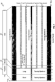
- FIG. 1 shows a PDU format 100 defined by IEEE 802.11 and suitable for use for various communication systems.
- PDU PHY protocol data units
- Each PDU 110 for IEEE 802.11 includes a preamble section 120, a signal section 130, and a data section 150.
- Preamble section 120 carries short and long training symbols that are described below.
- Signal section 130 carries one OFDM symbol for signaling for the PDU.
- Data section 150 carries a variable number of OFDM symbols for traffic/packet data for the PDU. The length of data section 150 is indicated by the signaling in signal section 130.
- Preamble section 120 carries ten short training symbols sent in two OFDM symbol periods followed by two long training symbols sent in two OFDM symbol periods.
- Four short training symbols are formed by performing an inverse discrete Fourier transform (IDFT) on a specific set of 12 pilot symbols sent on 12 subbands with indices of ⁇ -24, -20, -16, -12, -8, -4, 4, 8, 12, 16, 20, and 24 ⁇ .
- a "pilot symbol” is a modulation symbol for pilot and is typically known a priori by both the transmitting and receiving entities.
- the same set of 12 pilot symbols is used for all short training symbols.
- Each long training symbol is formed by performing an IDFT on a specific set of 52 pilot symbols sent on the 52 usable subbands.
- the same set of 52 pilot symbols is also used for both long training symbols.
- a receiving entity may use the short training symbols for signal detection, coarse frequency offset estimation, timing synchronization, automatic gain control (AGC), and so on.
- the receiving entity may use the long training symbols for channel estimation, fine
- Signaling and data are sent on the 48 data subbands in signal section 130 and data section 150, respectively.
- a carrier pilot is sent on the four pilot subbands in the signal and data sections.
- the carrier pilot is composed of four pilot symbols that are sent on the four pilot subbands across the signal and data sections.
- the pilot symbol for each pilot subband is multiplied with a 127-chip circularly extended pseudo-random number (PN) sequence to generate a predetermined symbol sequence for that pilot subband.
- PN pseudo-random number
- the receiving entity may use the carrier pilot to track the phase of a carrier signal across the signal and data sections.
- the pilot structure shown in FIG. 1 comprises ten short training symbols, two long training symbols, and the carrier pilot. This pilot structure is generally suitable for a SISO system.
- a MIMO system may utilize different types of pilot to support various functions needed for proper system operation, such as timing and frequency acquisition, channel estimation, calibration, and so on.
- Table 1 lists four types of pilot and their short description. A pilot is also called a "reference", and these two terms are often used interchangeably.
- Table 1 - Pilot Types Pilot Type Description Beacon Pilot A pilot transmitted from all transmit antennas and used for timing and frequency acquisition. Unsteered MIMO Pilot A pilot transmitted from all transmit antennas and used for channel estimation, with the pilot transmission from each transmit antenna being identifiable by a receiving entity.
- Steered MIMO Pilot A pilot transmitted on "eigenmodes" of a MIMO channel and used for channel estimation and possibly rate control.
- Carrier Pilot A pilot used for phase tracking of a carrier signal. The unsteered and steered MIMO pilots are described in detail below.
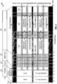
- FIG. 2 shows an exemplary PDU format 200 suitable for the MIMO system.
- a PDU 210 for this format includes a preamble section 220, a signal section 230, a MIMO pilot section 240, and a data section 250.
- Preamble section 220 carries the beacon pilot.
- the beacon pilot is composed of ten short training symbols and two long training symbols.
- Preamble section 220 is thus similar to preamble section 120 in FIG. 1 .
- Signal section 230 carries signaling for PDU 210 and may include (1) a field that indicates whether the PDU has format 200 or some other format (e.g., format 100) and (2) a field that indicates the length of MIMO pilot section 240.
- MIMO pilot section 240 carries a "base" MIMO pilot, which may be unsteered or steered.
- the base MIMO pilot is typically sent in each PDU and may be transmitted in the same manner as the data in the PDU.
- Data section 250 carries the data for PDU 210.
- a carrier pilot is sent on the four pilot subbands in signal section 230, MIMO pilot section 240, and data section 250.
- a PDU may also be called a packet, a data unit, a frame, a slot, a block, or some other terminology.
- PDU format 200 includes an exemplary pilot structure for the MIMO system.
- the pilot structure may include a minimal (or nominal) amount of pilot (the base pilot) needed for proper system operation under normal channel conditions.
- MIMO pilot section 240 may carry T OFDM symbols for the MIMO pilot for T transmit antennas.
- Additional pilot may be adaptively inserted and sent if and as needed in order to achieve improved performance.
- the additional pilot may be beneficial under certain adverse channel conditions such as increased fade rates due to Doppler effect, changing interference and/or jamming characteristics, and so on.
- the additional pilot may also be sent based on other factors, e.g., if the PDU is for a retransmission because an acknowledgment (ACK) was not received for a prior transmission of the PDU.
- the additional pilot may be inserted in the data section of the PDU. Signaling to indicate transmission of the additional pilot may be efficiently embedded within the carrier pilot, as described below, or sent in signal section 230.
- the receiving entity may obtain an estimate of ( k ) for each subband k based on an unsteered MIMO pilot sent by the transmitting entity.
- the unsteered MIMO pilot comprises T pilot transmissions sent from T transmit antennas, where the pilot transmission from each transmit antenna is identifiable by the receiving entity. This may be achieved by sending the pilot transmission for each transmit antenna with a different orthogonal (e.g., Walsh) sequence using code multiplexing, on a different subband using subband multiplexing, in a different symbol period using time multiplexing, and so on.
- a "transmit symbol” is a symbol to be sent from a transmit antenna.
- the same Walsh matrix W ( n ) may be used for all subbands and may thus not be a function of subband index k .
- Walsh matrix W (1) then contains the first element of the four Walsh sequences along its diagonal, (2) contains the second element of the four Walsh sequences, (3) contains the third element of the four Walsh sequences, and (4) contains the fourth element of the four Walsh sequences.
- the four Walsh matrices (1) through (4) may be used in four symbol periods to transmit the unsteered MIMO pilot.
- a complete unsteered MIMO pilot may be sent in T (consecutive or non-consecutive) symbol periods with code multiplexing, or one symbol period for each chip of the orthogonal sequence.
- the receiving entity may perform the complementary processing on the received pilot to estimate H ( k ).
- the transmitting entity may transmit data on S eigenmodes of the channel response matrix H ( k ) for each subband k to achieve improved performance.
- the columns of a unitary matrix are orthogonal to one another.
- the transmitting entity may use the right eigenvectors in V ( k ) for spatial processing to transmit data on the S eigenmodes of H ( k ).
- the receiving entity may use the left eigenvectors in U ( k ) for receiver spatial processing to recover the data transmitted on the S eigenmodes of H ( k ).
- the diagonal matrix ⁇ ( k ) contains non-negative real values along the diagonal and zeros elsewhere. These diagonal entries are referred to as singular values of H ( k ) and represent the channel gains for the S eigenmodes of H ( k ).
- Singular value decomposition is described by Gilbert Strang in “Linear Algebra and Its Applications,” Second Edition, Academic Press, 1980 .
- the transmitting entity may transmit a steered MIMO pilot as follows:
- a "received symbol” is a symbol obtained from a receive antenna.
- the transmitting entity may transmit a complete steered MIMO pilot on all S eigenmodes of H ( k ) in S symbol periods, e.g., on one eigenmode per symbol period using time multiplexing as shown in equation (4).
- the receiving entity may obtain an estimate of U ( k ), one column at a time, based on the steered MIMO pilot sent using time multiplexing, as shown in equation (5).
- the transmitting entity may also transmit the steered MIMO pilot on all S eigenmodes of H ( k ) concurrently in S symbol periods using coding multiplexing.
- the steered MIMO pilot with code multiplexing may be expressed as: where ( k,n ) is a matrix of right eigenvectors of H ( k , n ) for subband k in symbol period n.
- the receiving entity may obtain an estimate of U ( k,n ) after receiving the complete steered MIMO pilot.
- the transmitting entity may also transmit the complete steered MIMO pilot for all S eigenmodes of H ( k ) on S subbands k through k + S -1 in one symbol period using subband multiplexing.
- the transmitting entity may also transmit the steered MIMO pilot on less than S eigenmodes.
- the transmitting entity may transmit the steered MIMO pilot on the best or principal eigenmode in one symbol period, on the two best eigenmodes in two symbol periods, and so on.
- the transmitting entity may transmit the unsteered and steered MIMO pilots in various manners using code, subband, and/or time multiplexing.
- Code multiplexing allows the transmitting entity to use the maximum transmit power available for each transmit antenna for pilot transmission, which may improve channel estimation performance.
- the additional pilot may be a MIMO pilot, as described above.
- the additional pilot may also be some other type of pilot.
- the transmitting entity may transmit a single stream of pilot symbols on a single eigenmode or may beam steer a single stream of pilot symbols in some other manner.
- This additional pilot may be used, for example, to drive the timing offset, correct residual frequency offset, and so on.
- the pilot structure includes the base pilot (e.g., MIMO pilot section 240 in FIG. 2 ) that provides good performance under nominal channel conditions. This results in low overhead for the pilot.
- Additional pilot may be transmitted if and as needed.
- the amount of additional pilot to be sent as well as the placement of the additional pilot within a PDU may be flexibly selected based on the channel conditions and/or other factors. For example, a larger amount of additional pilot may be sent under more severe channel conditions.
- the additional pilot may be sent at or near the start of a PDU, which may simplify channel estimation and data detection and may further reduce buffering requirement.
- the additional pilot may also be dispersed throughout a PDU, which may improve performance for a time-varying channel.
- BPSK binary phase shift keying
- detection performance for the signaling embedded in the four pilot symbols degrades in proportion to the number of signaling values defined for these pilot symbols.
- the receiving entity receives noisy versions of the four pilot symbols and needs to ascertain the specific signaling value sent by the transmitting entity based on these noisy received pilot symbols.
- the receiving entity may compute a metric (e.g., a distance) between the received pilot symbols and the set of pilot symbols for each valid signaling value.
- the receiving entity selects the signaling value with the best metric (e.g., the shortest distance) as the value sent by the transmitting entity. Detection error is more likely when there are more valid signaling values from which to choose.
- the four pilot symbols are used to indicate whether data or additional pilot is being sent in the OFDM symbol.
- Table 2 shows an exemplary signaling set for this embodiment with four bits b 1 , b 2 , b 3 , and b 4 carried by the four pilot symbols with BPSK.
- Table 2 Bits Value Definition b 1 b 2 b 3 b 4 '0000' Data is being sent in the OFDM symbol '1111' MIMO pilot is being sent in the OFDM symbol
- the additional MIMO pilot may be steered or unsteered, e.g., may be sent in the same manner as data symbols in the PDU.
- a "data symbol” is a modulation symbol for data.
- the 4B bits are used to indicate whether additional pilot is being sent in the OFDM symbol and, if yes, specific information for the additional pilot.
- Table 3 shows an exemplary signaling set for this embodiment with four bits b 1 , b 2 , b 3 , and b 4 carried by the four pilot symbols with BPSK.
- bits b 1 and b 2 indicate whether an unsteered MIMO pilot, a steered MIMO pilot, or no additional pilot is being sent in the OFDM symbol.
- Bit b 3 indicates whether the MIMO pilot is being sent using code/time multiplexing or subband multiplexing.
- code multiplexing the MIMO pilot is sent over multiple symbol periods using orthogonal sequences.
- an unsteered MIMO pilot may be sent from four transmit antennas in four symbol periods using 4-chip Walsh sequences, as shown in equation (2).
- a steered MIMO pilot may be sent on all four eigenmodes concurrently in four symbol periods using 4-chip Walsh sequences, as shown in equation (6).
- the MIMO pilot is sent on multiple subbands in one symbol period.
- an unsteered MIMO pilot may be sent from four transmit antennas on four different subbands in one symbol period (e.g., from transmit antenna 1 on subband k, from transmit antenna 2 on subband k + 1, from transmit antenna 3 on subband k + 2, and from transmit antenna 4 on subband k + 3).
- a steered MIMO pilot may be sent on four eigenmodes using four different subbands in one symbol period (e.g., on eigenmode 1 using subband k , on eigenmode 2 using subband k + 1 , on eigenmode 3 using subband k + 2, and on eigenmode 4 using subband k + 3).
- Bit b 4 indicates the number of subbands used for the additional pilot.
- additional pilot symbols may be sent on all 48 data subbands or on only 24 data subbands (e.g., every other data subband).
- Tables 2 and 3 show two specific embodiments of the signaling embedded in the four pilot subbands with four bits using BPSK.
- the 4B bits for the carrier pilot may be used to convey any type of information for the additional pilot such as (1) whether or not the additional pilot is being sent, (2) the type of additional pilot being sent (e.g., unsteered MIMO pilot, steered MIMO pilot, and so on), (3) the manner in which the pilot is being sent (e.g., code multiplexing, subband multiplexing, time multiplexing, and so on), (4) the number of subbands used for the additional pilot (e.g., all, half, quarter, or some other number of data subbands), and (5) possibly other pertinent information.
- More signaling values provide more flexibility in the transmission of the additional pilot. However, detection performance is also worse with more signaling values. A tradeoff may be made between detection performance and pilot insertion flexibility.
- the signaling for the additional pilot in a given PDU may also be sent in signal section 230 of the PDU.
- This signaling may indicate any or all of the possible information noted above for the additional pilot.
- this signaling may indicate the specific symbol periods in which the additional pilot will be sent (e.g., in the middle of data section 250, in every quarter of the data section, in every L-th symbol period, and so on).
- the carrier pilot may be used to send signaling for the additional pilot, as described above.
- the carrier pilot may also be used to send other types of signaling such as, for example, the rate (e.g., coding and modulation scheme) used for a PDU being sent, the rate to be used for the other link (e.g., downlink or uplink), power control information (e.g., UP and DOWN power control commands used to adjust transmit power), transmission parameters (e.g., the allocated traffic channels, frequency subbands, and so on), an acknowledgment (ACK) or a negative acknowledgment (NAK) for a PDU received via the other link, a set of base station(s) to use for communication, and so on.
- the rate e.g., coding and modulation scheme
- the rate to be used for the other link e.g., downlink or uplink
- power control information e.g., UP and DOWN power control commands used to adjust transmit power
- transmission parameters e.g., the allocated traffic channels, frequency
- Different types of signaling may have different reliability requirements and may employ different encoding schemes and/or different signaling sets. Regardless of the type of signaling to be sent, the transmitting entity may conveniently send this signaling on the pilot subbands, and the receiving entity may quickly detect this signaling.
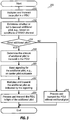
- FIG. 3 shows a flow diagram of a process 300 performed by the transmitting entity to send additional pilot.
- Process 300 may be performed for each PDU.
- the transmitting entity multiplexes and transmits the base pilot in the PDU (block 310).
- the transmitting entity also determines whether or not to transmit additional pilot in the PDU, e.g., based on channel conditions and/or other factors (block 312). If additional pilot is not to be sent in the PDU, as determined in block 314, then the transmitting entity processes and transmits the PDU in the normal manner without any additional pilot (block 316).
- the transmitting entity determines the amount, type, location, and so on, of the additional pilot to be sent in the PDU, e.g., based on the channel conditions and/or other factors (block 318).
- the transmitting entity then sends signaling for the additional pilot in the PDU, e.g., embedded in the pilot symbols sent on the four pilot subbands (block 320).
- the transmitting entity also multiplexes and transmits the additional pilot as indicated by the signaling (block 322).
- the transmitting entity also processes and transmits the PDU in light of the additional pilot (block 324). For example, the length of the PDU may be extended by the amount of additional pilot being sent in the PDU.
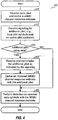
- FIG. 4 shows a flow diagram of a process 400 performed by the receiving entity to receive and utilize the additional pilot.
- Process 400 may also be performed for each PDU.
- the receiving entity receives the base pilot (e.g., the MIMO pilot sent in MIMO pilot section 240) and derives a MIMO channel response estimate based on the received base pilot (block 410).
- the receiving entity receives signaling for the additional pilot, e.g., from the pilot symbols sent on the four pilot subbands (block 412).
- the receiving entity determines whether or not additional pilot is being sent based on the received signaling (block 414). If additional pilot is not being sent, then the process proceeds to block 420. Otherwise, the receiving entity receives and demultiplexes the additional pilot as indicated by the received signaling (block 416).
- the receiving entity then derives an improved MIMO channel response estimate with the additional pilot (block 418).
- the receiving entity uses the channel response estimate to perform data detection on received data symbols for the PDU (block 420).
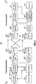
- FIG. 5 shows a block diagram of a transmitting entity 510 and a receiving entity 550 in a MIMO system 500.
- Transmitting entity 510 may be an access point or a user terminal.
- Receiving entity 550 may also be an access point or a user terminal.
- a TX data processor 512 processes (e.g., encodes, interleaves, and symbol maps) traffic/packet data to obtain data symbols.
- a TX spatial processor 520 receives and demultiplexes pilot and data symbols onto the proper subbands, performs spatial processing as appropriate, and provides T streams of transmit symbols for the T transmit antennas to T OFDM modulators (Mod) 530a through 530t.
- Each OFDM modulator 530 performs OFDM modulation on a respective transmit symbol stream and provides a stream of samples to an associated transmitter unit (TMTR) 532.
- Each transmitter unit 532 processes (e.g., converts to analog, amplifies, filters, and frequency upconverts) its sample stream to generate a modulated signal.
- Transmitter units 532a through 532t provide T modulated signals for transmission from T antennas 534a through 534t, respectively.
- R antennas 552a through 552r receive the T transmitted signals, and each antenna 552 provides a received signal to a respective receiver unit (RCVR) 554.
- Each receiver unit 554 processes its received signal and provides a corresponding sample stream to an associated OFDM demodulator (Demod) 560.
- Each OFDM demodulator 560 performs OFDM demodulation on its sample stream and provides received data symbols to a receive (RX) spatial processor 570 and received pilot symbols to a channel estimator 584 within a controller 580.
- Channel estimator 584 derives channel response estimates for the MIMO channel between transmitting entity 510 and receiving entity 550 for subbands used for data transmission. The channel response estimates may be derived with the base pilot and/or the additional pilot sent by transmitting entity 510.
- Controller 580 also derives spatial filter matrices based on the MIMO channel response estimates.
- RX spatial processor 570 performs receiver spatial processing (or spatial matched filtering) on the received data symbols for each subband with the spatial filter matrix derived for that subband and provides detected data symbols for the subband. Each detected data symbol is an estimate of a data symbol sent by transmitting entity 510.
- An RX data processor 572 then processes the detected data symbols for all subbands and provides decoded data.
- Controllers 540 and 580 control the operation of the processing units at transmitting entity 510 and receiving entity 550, respectively.
- Memory units 542 and 582 store data and/or program codes used by controllers 540 and 580, respectively.
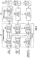
- FIG. 6 shows a block diagram of an embodiment of TX spatial processor 520 at transmitting entity 510.
- a TX data spatial processor 610 receives and performs spatial processing on the data symbols for transmission via the T transmit antennas or the S eigenmodes of each data subband.
- TX data spatial processor 610 provides T streams of spatially processed data symbols for the T transmit antennas to T symbol multiplexers (Mux) 640a through 640t.
- a TX pilot spatial processor 620 performs spatial processing on pilot symbols and provides (1) an unsteered MIMO pilot for transmission from the T transmit antennas or (2) a steered MIMO pilot for transmission on up to S eigenmodes of each subband used for pilot transmission.
- TX pilot spatial processor 620 provides spatially processed pilot symbols for the T transmit antennas to T symbol multiplexers 640a through 640t.
- a TX pilot signaling processor 630 generates signaling for the additional pilot, if any, being sent.
- the signaling for the additional pilot is embedded within the pilot symbols sent on the four pilot subbands for the carrier pilot.
- TX pilot signaling processor 630 provides carrier pilot symbols, with the signaling embedded therein, to symbol multiplexers 640a through 640t.
- Each symbol multiplexer 640 receives and multiplexes the spatially processed data symbols, the spatially processed pilot symbols, and the carrier pilot symbols for its transmit antenna onto the proper subband and symbol period.
- T symbol multiplexers 640a through 640t provide T streams for transmit symbols for the T transmit antennas to T OFDM modulators 530a through 530t.
- Each OFDM modulator 530 performs OFDM modulation on a respective transmit symbol stream and provides a corresponding OFDM symbol stream. For each symbol period, each OFDM modulator 530 obtains K frequency-domain values, e.g., for 48 data and/or pilot symbols to be sent on the 48 data subbands, four carrier pilot symbols to be sent on the four pilot subbands, and 12 signal values of zero for the 12 unused subbands.
- An inverse fast Fourier transform (IFFT) unit 650 transforms the K frequency-domain values to the time domain with a K-point IFFT and provides a "transformed" symbol that contains K time-domain chips.
- IFFT inverse fast Fourier transform
- a cyclic prefix generator 652 repeats a portion of each transformed symbol to form a corresponding OFDM symbol.
- the repeated portion is often called a cyclic prefix or guard interval.
- An OFDM symbol period (or simply, a symbol period) is the duration of one OFDM symbol.
- FIG. 7 shows a block diagram of an embodiment of TX pilot signaling processor 630.
- Controller 540 provides a signaling value for the additional pilot to a signaling look-up table (LUT) 710, which then provides four pilot symbols corresponding to this signaling value to four multipliers 712a through 712d.
- Each multiplier 712 also receive a PN sequence from a PN generator 714 and, for each symbol period, multiplies the pilot symbol for that symbol period with the PN value for that symbol period to generate a scrambled pilot symbol.
- Multipliers 712a through 712d provide four scrambled pilot symbols for the four pilot subbands to T symbol multiplexers 640a through 640t.
- pilot transmission and signaling techniques described herein may be implemented by various means. For example, these techniques may be implemented in hardware, software, or a combination thereof.
- the processing units used to transmit additional pilot and signaling may be implemented within one or more application specific integrated circuits (ASICs), digital signal processors (DSPs), digital signal processing devices (DSPDs), programmable logic devices (PLDs), field programmable gate arrays (FPGAs), processors, controllers, micro-controllers, microprocessors, other electronic units designed to perform the functions described herein, or a combination thereof.
- ASICs application specific integrated circuits
- DSPs digital signal processors
- DSPDs digital signal processing devices
- PLDs programmable logic devices
- FPGAs field programmable gate arrays
- processors controllers, micro-controllers, microprocessors, other electronic units designed to perform the functions described herein, or a combination thereof.
- the processing units used to receive the additional pilot and signaling may also be implemented within one or more ASICs, D
- the techniques described herein may be implemented with modules (e.g., procedures, functions, and so on) that perform the functions described herein.
- the software codes may be stored in a memory unit (e.g., memory units 542 and/or 582 in FIG. 5 ) and executed by a processor (e.g., controller 540 and/or 580 in FIG. 5 ).
- the memory unit may be implemented within the processor or external to the processor, in which case it can be communicatively coupled to the processor via various means as is known in the art.
Landscapes
- Engineering & Computer Science (AREA)
- Signal Processing (AREA)
- Computer Networks & Wireless Communication (AREA)
- Power Engineering (AREA)
- Quality & Reliability (AREA)
- Radio Transmission System (AREA)
- Mobile Radio Communication Systems (AREA)
Claims (11)
- Procédé (300) de transmission de signalisation dans un système de communication à entrées multiples et sorties multiples, MIMO, utilisant un multiplexage par répartition en fréquences orthogonales, OFDM, comprenant :la sélection d'une valeur de signalisation parmi une pluralité de valeurs de signalisation, dans lequel la valeur de signalisation sélectionnée indique si des symboles de pilotes supplémentaires ou des symboles de données doivent être transmis ;la sélection d'un ensemble de symboles de pilotes parmi une pluralité d'ensembles de symboles de pilotes, dans lequel chacun de la pluralité d'ensembles de symboles de pilotes correspond à une valeur différente de la pluralité de valeurs de signalisation, et dans lequel l'ensemble sélectionné de symboles de pilotes correspond à la valeur de signalisation sélectionnée ;le multiplexage (320) de l'ensemble sélectionné de symboles de pilotes sur un premier ensemble de sous-bandes de fréquences utilisées pour un pilote de porteuse ; etla transmission (322), tels qu'indiqué par la valeur de signalisation sélectionnée, des symboles de pilotes supplémentaires ou des symboles de données sur un second ensemble de sous-bandes de fréquences simultanément avec l'ensemble sélectionné de symboles de pilotes ;dans lequel la valeur de signalisation sélectionnée indique un nombre de sous-bandes utilisées pour les symboles de pilotes supplémentaires et dans lequel la quantité de symboles de pilotes supplémentaires ainsi que leur emplacement à l'intérieur d'une unité de données de protocole, PDU, sont basés sur des conditions de canal.
- Procédé selon la revendication 1, dans lequel le pilote de porteuse est approprié pour être utilisé par une entité de réception pour suivre une phase d'un signal de porteuse utilisé par une entité de transmission.
- Procédé selon la revendication 1 ou 2, dans lequel la valeur de signalisation sélectionnée indique un type des symboles de pilotes supplémentaires.
- Procédé selon l'une des revendications 1 à 3, dans lequel la valeur de signalisation sélectionnée indique le second ensemble de sous-bandes de fréquences pour une transmission des symboles de pilotes supplémentaires.
- Procédé selon l'une des revendications 1 à 4, dans lequel la valeur de signalisation sélectionnée indique un mode de transmission pour les symboles de pilotes supplémentaires.
- Appareil dans un système de communication à entrées multiples et sorties multiples, MIMO, utilisant un multiplexage par répartition en fréquences orthogonales, OFDM, comprenant :des moyens pour sélectionner une valeur de signalisation parmi une pluralité de valeurs de signalisation, dans lequel la valeur de signalisation sélectionnée indique si des symboles de pilotes supplémentaires ou des symboles de données doivent être transmis ; et dans lequel la valeur de signalisation sélectionnée indique en outre un nombre de sous-bandes utilisées pour les symboles de pilotes supplémentaires ;des moyens pour sélectionner un ensemble de symboles de pilotes parmi une pluralité d'ensembles de symboles de pilotes, dans lequel chacun de la pluralité d'ensembles de symboles de pilotes correspond à une valeur différente de la pluralité de valeurs de signalisation, et dans lequel l'ensemble sélectionné de symboles de pilotes correspond à la valeur de signalisation sélectionnée ;des moyens pour multiplexer l'ensemble sélectionné de symboles de pilotes sur un premier ensemble de sous-bandes de fréquences utilisées pour un pilote de porteuse ; etdes moyens pour transmettre, tels qu'indiqué par la valeur de signalisation sélectionnée, les symboles de pilotes supplémentaires ou les symboles de données sur un second ensemble de sous-bandes de fréquences simultanément avec l'ensemble sélectionné de symboles de pilotes ;dans lequel la valeur de signalisation sélectionnée indique un nombre de sous-bandes utilisées pour les symboles de pilotes supplémentaires, et dans lequel la quantité de symboles de pilotes supplémentaires ainsi que leur emplacement à l'intérieur d'une unité de données de protocole, PDU, sont basés sur des conditions de canal.
- Appareil selon la revendication 6, dans lequel le pilote de porteuse est approprié pour être utilisé par une entité de réception pour suivre une phase d'un signal de porteuse utilisé par une entité de transmission.
- Appareil selon la revendication 6 ou 7, dans lequel la valeur de signalisation sélectionnée indique un type des symboles de pilotes supplémentaires.
- Appareil selon l'une des revendications 6 à 8, dans lequel la valeur de signalisation sélectionnée indique le second ensemble de sous-bandes de fréquences pour la transmission des symboles de pilotes supplémentaires.
- Appareil selon l'une des revendications 6 à 9, dans lequel la valeur de signalisation sélectionnée indique un mode de transmission pour les symboles de pilotes supplémentaires.
- Support de stockage comprenant du code logiciel pour mettre en oeuvre un procédé selon l'une des revendications 1 à 5 lorsqu'il est exécuté par un processeur.
Priority Applications (1)
| Application Number | Priority Date | Filing Date | Title |
|---|---|---|---|
| EP19171948.3A EP3537674B1 (fr) | 2004-07-20 | 2005-07-07 | Insertion de pilote adaptative pour un système mimo-ofdm |
Applications Claiming Priority (3)
| Application Number | Priority Date | Filing Date | Title |
|---|---|---|---|
| US10/896,277 US8000221B2 (en) | 2004-07-20 | 2004-07-20 | Adaptive pilot insertion for a MIMO-OFDM system |
| PCT/US2005/023979 WO2006019579A2 (fr) | 2004-07-20 | 2005-07-07 | Insertion adaptative d'un pilote pour systeme mimo-ofdm |
| EP05770166A EP1774736B1 (fr) | 2004-07-20 | 2005-07-07 | Insertion adaptative d'un pilote pour systeme mimo-ofdm |
Related Parent Applications (2)
| Application Number | Title | Priority Date | Filing Date |
|---|---|---|---|
| EP05770166A Division EP1774736B1 (fr) | 2004-07-20 | 2005-07-07 | Insertion adaptative d'un pilote pour systeme mimo-ofdm |
| EP05770166.6 Division | 2005-07-07 |
Related Child Applications (1)
| Application Number | Title | Priority Date | Filing Date |
|---|---|---|---|
| EP19171948.3A Division EP3537674B1 (fr) | 2004-07-20 | 2005-07-07 | Insertion de pilote adaptative pour un système mimo-ofdm |
Publications (2)
| Publication Number | Publication Date |
|---|---|
| EP2395719A1 EP2395719A1 (fr) | 2011-12-14 |
| EP2395719B1 true EP2395719B1 (fr) | 2019-05-01 |
Family
ID=35063100
Family Applications (4)
| Application Number | Title | Priority Date | Filing Date |
|---|---|---|---|
| EP11166524.6A Active EP2395719B1 (fr) | 2004-07-20 | 2005-07-07 | Insertion de pilote adaptative pour un système MIMO-OFDM |
| EP12153312.9A Active EP2453619B1 (fr) | 2004-07-20 | 2005-07-07 | Insertion adaptative de pilote pour un système MIMO-OFDM |
| EP19171948.3A Active EP3537674B1 (fr) | 2004-07-20 | 2005-07-07 | Insertion de pilote adaptative pour un système mimo-ofdm |
| EP05770166A Active EP1774736B1 (fr) | 2004-07-20 | 2005-07-07 | Insertion adaptative d'un pilote pour systeme mimo-ofdm |
Family Applications After (3)
| Application Number | Title | Priority Date | Filing Date |
|---|---|---|---|
| EP12153312.9A Active EP2453619B1 (fr) | 2004-07-20 | 2005-07-07 | Insertion adaptative de pilote pour un système MIMO-OFDM |
| EP19171948.3A Active EP3537674B1 (fr) | 2004-07-20 | 2005-07-07 | Insertion de pilote adaptative pour un système mimo-ofdm |
| EP05770166A Active EP1774736B1 (fr) | 2004-07-20 | 2005-07-07 | Insertion adaptative d'un pilote pour systeme mimo-ofdm |
Country Status (11)
| Country | Link |
|---|---|
| US (2) | US8000221B2 (fr) |
| EP (4) | EP2395719B1 (fr) |
| JP (2) | JP4690401B2 (fr) |
| KR (2) | KR20070026892A (fr) |
| CN (2) | CN101023643B (fr) |
| CA (2) | CA2574740C (fr) |
| ES (3) | ES2478519T3 (fr) |
| HU (1) | HUE044471T2 (fr) |
| MY (1) | MY154786A (fr) |
| TW (1) | TWI358215B (fr) |
| WO (1) | WO2006019579A2 (fr) |
Families Citing this family (51)
| Publication number | Priority date | Publication date | Assignee | Title |
|---|---|---|---|---|
| US8000221B2 (en) * | 2004-07-20 | 2011-08-16 | Qualcomm, Incorporated | Adaptive pilot insertion for a MIMO-OFDM system |
| US7372913B2 (en) * | 2004-07-22 | 2008-05-13 | Qualcomm Incorporated | Pilot tones in a multi-transmit OFDM system usable to capture transmitter diversity benefits |
| EP2330777B1 (fr) | 2004-08-12 | 2018-03-21 | InterDigital Technology Corporation | Procédé et système permettant de commander l'accès à un support de communications sans fil |
| US20060045192A1 (en) * | 2004-08-25 | 2006-03-02 | Hiroshi Hayashi | Method and apparatus for pilot channel transmission and reception within a multi-carrier communication system |
| US7656969B2 (en) * | 2005-01-14 | 2010-02-02 | Motorola, Inc. | Dual payload and adaptive modulation |
| CN101112017B (zh) * | 2005-02-03 | 2011-06-01 | 富士通株式会社 | 无线通信系统及无线通信方法 |
| US20060245509A1 (en) * | 2005-04-27 | 2006-11-02 | Samsung Electronics Co., Ltd | Method and system for processing MIMO pilot signals in an orthogonal frequency division multiplexing network |
| US20070004465A1 (en) * | 2005-06-29 | 2007-01-04 | Aris Papasakellariou | Pilot Channel Design for Communication Systems |
| WO2007013559A1 (fr) * | 2005-07-29 | 2007-02-01 | Matsushita Electric Industrial Co., Ltd. | Dispositif et procédé de communication sans fil |
| US7508842B2 (en) * | 2005-08-18 | 2009-03-24 | Motorola, Inc. | Method and apparatus for pilot signal transmission |
| TR201904500T4 (tr) * | 2005-09-27 | 2019-05-21 | Nokia Technologies Oy | Çok taşıyıcılı iletimler için pilot yapısı. |
| KR100668663B1 (ko) * | 2005-09-30 | 2007-01-12 | 한국전자통신연구원 | Ofdm 시스템에서 이동국의 자동이득제어 장치 및 방법 |
| US8351518B2 (en) * | 2005-09-30 | 2013-01-08 | Sharp Kabushiki Kaisha | Wireless transmitting apparatus, wireless receiving apparatus, wireless communication system, wireless transmitting method and wireless receiving method |
| EP2840724B1 (fr) * | 2005-09-30 | 2019-11-20 | Apple Inc. | Système de communication mimo |
| KR101221706B1 (ko) * | 2006-01-25 | 2013-01-11 | 삼성전자주식회사 | 고속 패킷 데이터 시스템의 순방향 링크에서 다중 입력 다중 출력 기술을 지원하는 송수신 장치 및 방법 |
| JP5013771B2 (ja) * | 2006-08-10 | 2012-08-29 | 日本放送協会 | Mimo−ofdmの雑音電力測定方法及び受信装置 |
| CN100563124C (zh) * | 2006-09-07 | 2009-11-25 | 华为技术有限公司 | 多天线多载波系统中的导频序列发送方法及系统 |
| TWI448091B (zh) | 2006-12-04 | 2014-08-01 | Interdigital Tech Corp | 致能多頻帶傳輸方法及裝置 |
| JP4907721B2 (ja) * | 2006-12-07 | 2012-04-04 | インターデイジタル テクノロジー コーポレーション | トレーニング信号および情報ビットを割り当てるための無線通信方法および装置 |
| AU2012202767B2 (en) * | 2007-03-21 | 2015-01-15 | Interdigital Technology Corporation | MIMO wireless communication method and apparatus for transmitting and decoding resource block structures |
| WO2008115588A2 (fr) | 2007-03-21 | 2008-09-25 | Interdigital Technology Corporation | Procédé et appareil de radiocommunication mimo pour l'émission et le décodage de structures de blocs de ressources sur la base d'un mode à signal de référence dédié |
| JP2010531614A (ja) * | 2007-06-27 | 2010-09-24 | テレフオンアクチーボラゲット エル エム エリクソン(パブル) | Mimoシステムにおける無線リソース割り当てを改善するための方法及び装置 |
| EP2193640B1 (fr) * | 2007-08-31 | 2020-02-12 | Panasonic Corporation | Appareil de communication, procédé de communication et circuit intégré |
| WO2009083927A1 (fr) * | 2008-01-02 | 2009-07-09 | Nxp B.V. | Procédé et système pour un schéma de transmission de séquence d'intervalles de temps de pilote de liaison montante supplémentaire |
| EP2114029A1 (fr) * | 2008-04-28 | 2009-11-04 | Nokia Siemens Networks Oy | Procédé et dispositif pour la transmission de données dans un réseau de communication |
| CN102017557B (zh) * | 2008-07-18 | 2013-10-16 | 上海贝尔股份有限公司 | 在sc-fdma系统中对多路信号进行交换处理的方法和装置 |
| US8179920B2 (en) * | 2008-09-11 | 2012-05-15 | Entropic Communications, Inc. | High efficiency preambles for communications systems over pseudo-stationary communication channels |
| US8428018B2 (en) | 2008-09-26 | 2013-04-23 | Lg Electronics Inc. | Method of transmitting reference signals in a wireless communication having multiple antennas |
| US8274885B2 (en) | 2008-10-03 | 2012-09-25 | Wi-Lan, Inc. | System and method for data distribution in VHF/UHF bands |
| US8107547B2 (en) * | 2008-11-17 | 2012-01-31 | Texas Instruments Incorporated | Receivers for embedded ACK/NAK in CQI reference signals in wireless networks |
| US8107391B2 (en) | 2008-11-19 | 2012-01-31 | Wi-Lan, Inc. | Systems and etiquette for home gateways using white space |
| US8335204B2 (en) * | 2009-01-30 | 2012-12-18 | Wi-Lan, Inc. | Wireless local area network using TV white space spectrum and long term evolution system architecture |
| JP4893974B2 (ja) * | 2009-06-09 | 2012-03-07 | 株式会社エヌ・ティ・ティ・ドコモ | 無線通信装置、無線通信方法及び無線通信システム |
| KR101234004B1 (ko) | 2009-12-18 | 2013-02-18 | 한국전자통신연구원 | 여러 단말과 동시에 통신하는 무선 패킷 통신 시스템에서 데이터 송/수신 방법 |
| US8363613B2 (en) * | 2010-05-13 | 2013-01-29 | Juniper Networks, Inc. | Increasing throughput by adaptively changing PDU size in wireless networks under low SNR conditions |
| CN102025459B (zh) * | 2010-12-09 | 2014-05-07 | 南京大学 | 基于非参量估计ica的mimo-ofdm系统盲去卷积方法 |
| EP2651062B1 (fr) | 2010-12-10 | 2022-01-05 | Sun Patent Trust | Procédé de génération de signaux et dispositif de génération de signaux |
| TWI551174B (zh) * | 2010-12-31 | 2016-09-21 | 電信科學技術研究院 | 使用者設備雙工規格訊息之獲取方法及設備 |
| CN103220028B (zh) | 2012-01-21 | 2016-03-30 | 华为技术有限公司 | 导频信号发射方法、信道估计方法、装置及系统 |
| JP6267688B2 (ja) * | 2012-05-11 | 2018-01-24 | テレフオンアクチーボラゲット エルエム エリクソン(パブル) | マルチアンテナ無線通信システムにおける復調パイロットを送信する方法及び装置 |
| EP2853055B1 (fr) * | 2012-05-23 | 2019-05-08 | Telefonaktiebolaget LM Ericsson (publ) | Procédé et appareil pour transmettre des informations de pilote de démodulation dans un système de communication sans fil à plusieurs antennes |
| CN103475614B (zh) * | 2012-06-07 | 2017-05-03 | 普天信息技术研究院有限公司 | 频偏估计和补偿的方法和装置 |
| US9264101B2 (en) | 2013-03-28 | 2016-02-16 | Broadcom Corporation | Communication system with proactive network maintenance and methods for use therewith |
| RU2622027C1 (ru) * | 2013-05-31 | 2017-06-09 | Телефонактиеболагет Л М Эрикссон (Пабл) | Способы и пользовательское оборудование для демодуляции данных |
| US20150365982A1 (en) * | 2014-06-13 | 2015-12-17 | Sony Corporation | Massive mimo link setup |
| WO2016045130A1 (fr) * | 2014-09-28 | 2016-03-31 | 华为技术有限公司 | Procédé et dispositif de commande puissance de liaison montante |
| US10506523B2 (en) * | 2016-11-18 | 2019-12-10 | Qualcomm Incorporated | Subband set dependent uplink power control |
| CN107241289A (zh) | 2017-07-20 | 2017-10-10 | 重庆物奇科技有限公司 | 一种低压电力线宽带载波通信方法 |
| WO2019134164A1 (fr) * | 2018-01-08 | 2019-07-11 | 海能达通信股份有限公司 | Procédé et dispositif de transmission fiable pour réseau privé à large bande dans un canal mobile à grande vitesse |
| CN112350809B (zh) * | 2019-08-06 | 2023-12-08 | 华为技术有限公司 | 感知方法和通信装置 |
| CN111431827B (zh) * | 2020-05-07 | 2023-03-07 | 中国人民解放军63921部队 | 基于fft的分步递进高精度频率估计方法 |
Citations (1)
| Publication number | Priority date | Publication date | Assignee | Title |
|---|---|---|---|---|
| WO2004056022A2 (fr) * | 2002-12-13 | 2004-07-01 | Electronics And Telecommunications Research Institute | Dispositif et procede de constitution de signal pour liaison descendante de systeme cellulaire avec acces a multiplexage par repartition orhtogonale de la frequence |
Family Cites Families (30)
| Publication number | Priority date | Publication date | Assignee | Title |
|---|---|---|---|---|
| US3636524A (en) * | 1969-12-08 | 1972-01-18 | Tel Tech Corp | Multiplex communication system |
| US4949250A (en) * | 1988-03-18 | 1990-08-14 | Digital Equipment Corporation | Method and apparatus for executing instructions for a vector processing system |
| CA2071421C (fr) | 1991-06-19 | 2000-08-08 | Yoshiaki Kumagai | Circuit de commande automatique de frequence |
| SE515588C2 (sv) | 1996-01-25 | 2001-09-03 | Ericsson Telefon Ab L M | Miniceller med variabel för storlek på nyttolasten i ett mobiltelefonnät |
| US6370156B2 (en) | 1997-01-31 | 2002-04-09 | Alcatel | Modulation/demodulation of a pilot carrier, means and method to perform the modulation/demodulation |
| FI104610B (fi) | 1997-03-27 | 2000-02-29 | Nokia Networks Oy | Ohjauskanavan allokointi pakettiradioverkossa |
| JPH11186987A (ja) * | 1997-12-22 | 1999-07-09 | Matsushita Electric Ind Co Ltd | Cdma受信機位相追従装置 |
| AU6716500A (en) * | 1999-08-27 | 2001-03-26 | Nokia Corporation | Mobile multimedia terminal for dvb-t and large and small cell communication |
| JP4284773B2 (ja) | 1999-09-07 | 2009-06-24 | ソニー株式会社 | 送信装置、受信装置、通信システム、送信方法及び通信方法 |
| US6445693B1 (en) * | 1999-09-15 | 2002-09-03 | Lucent Technologies Inc. | Method and apparatus for estimating power of first adjacent analog FM interference in an in-band on-channel (IBOC) communication system |
| US6707856B1 (en) | 1999-10-07 | 2004-03-16 | Cisco Technology | Transmission of system configuration information |
| US6539211B1 (en) * | 2000-01-17 | 2003-03-25 | Qualcomm Incorporated | Efficient system and method for facilitating quick paging channel demodulation via an efficient offline searcher in a wireless communications system |
| US6473467B1 (en) | 2000-03-22 | 2002-10-29 | Qualcomm Incorporated | Method and apparatus for measuring reporting channel state information in a high efficiency, high performance communications system |
| KR100383618B1 (ko) * | 2000-06-21 | 2003-05-14 | 삼성전자주식회사 | 고속 데이터 전송을 지원하는 이동통신시스템에서데이터율 제어 채널 단속적 전송 장치 및 방법 |
| US7406104B2 (en) | 2000-08-25 | 2008-07-29 | Lin Yang | Terrestrial digital multimedia/television broadcasting system |
| US6567387B1 (en) * | 2000-11-07 | 2003-05-20 | Intel Corporation | System and method for data transmission from multiple wireless base transceiver stations to a subscriber unit |
| US7164669B2 (en) | 2001-01-19 | 2007-01-16 | Adaptix, Inc. | Multi-carrier communication with time division multiplexing and carrier-selective loading |
| US7310304B2 (en) * | 2001-04-24 | 2007-12-18 | Bae Systems Information And Electronic Systems Integration Inc. | Estimating channel parameters in multi-input, multi-output (MIMO) systems |
| US7145959B2 (en) * | 2001-04-25 | 2006-12-05 | Magnolia Broadband Inc. | Smart antenna based spectrum multiplexing using existing pilot signals for orthogonal frequency division multiplexing (OFDM) modulations |
| US6441786B1 (en) * | 2001-07-20 | 2002-08-27 | Motorola, Inc. | Adaptive antenna array and method for control thereof |
| DE10141971A1 (de) | 2001-08-28 | 2003-03-27 | Siemens Ag | Adaptive Kanalschätzung in einem OFDM-basierten Mobilfunksystem durch Variation der Anzahl der Pilotsymbole |
| US7773699B2 (en) | 2001-10-17 | 2010-08-10 | Nortel Networks Limited | Method and apparatus for channel quality measurements |
| KR100790114B1 (ko) * | 2002-03-16 | 2007-12-31 | 삼성전자주식회사 | 직교주파수 분할다중 접속 시스템에서 적응적 파일럿반송파 할당 방법 및 장치 |
| JP4334274B2 (ja) | 2002-05-16 | 2009-09-30 | 株式会社エヌ・ティ・ティ・ドコモ | マルチキャリア伝送用送信機及びマルチキャリア伝送方法 |
| CA2428576C (fr) | 2002-05-16 | 2008-10-07 | Ntt Docomo, Inc. | Emetteur pour emission multiporteuse et methode d'emission multiporteuse |
| US8320301B2 (en) | 2002-10-25 | 2012-11-27 | Qualcomm Incorporated | MIMO WLAN system |
| US7986742B2 (en) | 2002-10-25 | 2011-07-26 | Qualcomm Incorporated | Pilots for MIMO communication system |
| WO2004064434A2 (fr) | 2003-01-08 | 2004-07-29 | Nortel Networks Limited | Procede et appareil de mise a jour de localisations de stations mobiles inactives |
| US7039412B2 (en) | 2003-08-08 | 2006-05-02 | Intel Corporation | Method and apparatus for transmitting wireless signals on multiple frequency channels in a frequency agile network |
| US8000221B2 (en) | 2004-07-20 | 2011-08-16 | Qualcomm, Incorporated | Adaptive pilot insertion for a MIMO-OFDM system |
-
2004
- 2004-07-20 US US10/896,277 patent/US8000221B2/en active Active
-
2005
- 2005-07-07 WO PCT/US2005/023979 patent/WO2006019579A2/fr active Application Filing
- 2005-07-07 CA CA2574740A patent/CA2574740C/fr active Active
- 2005-07-07 EP EP11166524.6A patent/EP2395719B1/fr active Active
- 2005-07-07 KR KR1020077003996A patent/KR20070026892A/ko not_active Application Discontinuation
- 2005-07-07 JP JP2007522530A patent/JP4690401B2/ja active Active
- 2005-07-07 EP EP12153312.9A patent/EP2453619B1/fr active Active
- 2005-07-07 CN CN2005800313880A patent/CN101023643B/zh active Active
- 2005-07-07 ES ES12153312.9T patent/ES2478519T3/es active Active
- 2005-07-07 KR KR1020097003011A patent/KR100945955B1/ko active IP Right Grant
- 2005-07-07 ES ES05770166T patent/ES2389488T3/es active Active
- 2005-07-07 CN CN201110308350.0A patent/CN102361465B/zh active Active
- 2005-07-07 CA CA2851734A patent/CA2851734C/fr active Active
- 2005-07-07 EP EP19171948.3A patent/EP3537674B1/fr active Active
- 2005-07-07 ES ES11166524T patent/ES2739391T3/es active Active
- 2005-07-07 HU HUE11166524 patent/HUE044471T2/hu unknown
- 2005-07-07 EP EP05770166A patent/EP1774736B1/fr active Active
- 2005-07-14 MY MYPI20053228A patent/MY154786A/en unknown
- 2005-07-19 TW TW094124357A patent/TWI358215B/zh active
-
2009
- 2009-07-16 US US12/504,395 patent/US8547820B2/en not_active Expired - Lifetime
-
2010
- 2010-04-27 JP JP2010102282A patent/JP5341015B2/ja active Active
Patent Citations (1)
| Publication number | Priority date | Publication date | Assignee | Title |
|---|---|---|---|---|
| WO2004056022A2 (fr) * | 2002-12-13 | 2004-07-01 | Electronics And Telecommunications Research Institute | Dispositif et procede de constitution de signal pour liaison descendante de systeme cellulaire avec acces a multiplexage par repartition orhtogonale de la frequence |
Also Published As
Similar Documents
| Publication | Publication Date | Title |
|---|---|---|
| EP2395719B1 (fr) | Insertion de pilote adaptative pour un système MIMO-OFDM | |
| US10476560B2 (en) | Spatial spreading in a multi-antenna communication system | |
| EP1749360B1 (fr) | Sélection d'un mode et d'un débit de transmission pour un système de communication sans fil | |
| JP5053647B2 (ja) | Ofdmをベースにしたマルチアンテナ通信システムのための送信ダイバーシティおよび空間拡散 | |
| US7463576B2 (en) | Channel estimation for OFDM communication systems | |
| US8520498B2 (en) | Transmit diversity and spatial spreading for an OFDM-based multi-antenna communication system | |
| EP2257008B1 (fr) | Procédé et émetteur pour la transmission diffusée avec étalement spatial dans un système de télécommunication à antennes multiples | |
| US20050265275A1 (en) | Continuous beamforming for a MIMO-OFDM system | |
| US20060013250A1 (en) | Unified MIMO transmission and reception | |
| US20040136349A1 (en) | MIMO system with multiple spatial multiplexing modes | |
| KR100828466B1 (ko) | 다중-안테나 통신 시스템에서 공간 확산을 이용한브로드캐스트 송신 | |
| EP1933513A1 (fr) | Procédé et émetteur pour la transmission diffusée avec étalement spatial dans un système de télécommunication à antennes multiples |
Legal Events
| Date | Code | Title | Description |
|---|---|---|---|
| 17P | Request for examination filed |
Effective date: 20110518 |
|
| AC | Divisional application: reference to earlier application |
Ref document number: 1774736 Country of ref document: EP Kind code of ref document: P |
|
| AK | Designated contracting states |
Kind code of ref document: A1 Designated state(s): AT BE BG CH CY CZ DE DK EE ES FI FR GB GR HU IE IS IT LI LT LU LV MC NL PL PT RO SE SI SK TR |
|
| PUAI | Public reference made under article 153(3) epc to a published international application that has entered the european phase |
Free format text: ORIGINAL CODE: 0009012 |
|
| 17Q | First examination report despatched |
Effective date: 20140103 |
|
| STAA | Information on the status of an ep patent application or granted ep patent |
Free format text: STATUS: EXAMINATION IS IN PROGRESS |
|
| REG | Reference to a national code |
Ref country code: DE Ref legal event code: R079 Ref document number: 602005055728 Country of ref document: DE Free format text: PREVIOUS MAIN CLASS: H04L0025020000 Ipc: H04B0007041300 |
|
| GRAP | Despatch of communication of intention to grant a patent |
Free format text: ORIGINAL CODE: EPIDOSNIGR1 |
|
| STAA | Information on the status of an ep patent application or granted ep patent |
Free format text: STATUS: GRANT OF PATENT IS INTENDED |
|
| RIC1 | Information provided on ipc code assigned before grant |
Ipc: H04L 1/06 20060101ALI20181031BHEP Ipc: H04L 1/00 20060101ALI20181031BHEP Ipc: H04L 25/02 20060101ALI20181031BHEP Ipc: H04B 7/0413 20111214AFI20181031BHEP Ipc: H04L 27/26 20060101ALI20181031BHEP |
|
| INTG | Intention to grant announced |
Effective date: 20181119 |
|
| RIC1 | Information provided on ipc code assigned before grant |
Ipc: H04L 1/06 20060101ALI20181031BHEP Ipc: H04L 27/26 20060101ALI20181031BHEP Ipc: H04B 7/0413 20170101AFI20181031BHEP Ipc: H04L 25/02 20060101ALI20181031BHEP Ipc: H04L 1/00 20060101ALI20181031BHEP |
|
| RIC1 | Information provided on ipc code assigned before grant |
Ipc: H04L 25/02 20060101ALI20181031BHEP Ipc: H04B 7/0413 20170101AFI20181031BHEP Ipc: H04L 1/00 20060101ALI20181031BHEP Ipc: H04L 1/06 20060101ALI20181031BHEP Ipc: H04L 27/26 20060101ALI20181031BHEP |
|
| GRAS | Grant fee paid |
Free format text: ORIGINAL CODE: EPIDOSNIGR3 |
|
| GRAA | (expected) grant |
Free format text: ORIGINAL CODE: 0009210 |
|
| STAA | Information on the status of an ep patent application or granted ep patent |
Free format text: STATUS: THE PATENT HAS BEEN GRANTED |
|
| AC | Divisional application: reference to earlier application |
Ref document number: 1774736 Country of ref document: EP Kind code of ref document: P |
|
| AK | Designated contracting states |
Kind code of ref document: B1 Designated state(s): AT BE BG CH CY CZ DE DK EE ES FI FR GB GR HU IE IS IT LI LT LU LV MC NL PL PT RO SE SI SK TR |
|
| REG | Reference to a national code |
Ref country code: GB Ref legal event code: FG4D |
|
| REG | Reference to a national code |
Ref country code: CH Ref legal event code: EP Ref country code: AT Ref legal event code: REF Ref document number: 1128315 Country of ref document: AT Kind code of ref document: T Effective date: 20190515 |
|
| REG | Reference to a national code |
Ref country code: DE Ref legal event code: R096 Ref document number: 602005055728 Country of ref document: DE |
|
| REG | Reference to a national code |
Ref country code: IE Ref legal event code: FG4D |
|
| REG | Reference to a national code |
Ref country code: NL Ref legal event code: FP |
|
| REG | Reference to a national code |
Ref country code: LT Ref legal event code: MG4D |
|
| REG | Reference to a national code |
Ref country code: HU Ref legal event code: AG4A Ref document number: E044471 Country of ref document: HU |
|
| PG25 | Lapsed in a contracting state [announced via postgrant information from national office to epo] |
Ref country code: LT Free format text: LAPSE BECAUSE OF FAILURE TO SUBMIT A TRANSLATION OF THE DESCRIPTION OR TO PAY THE FEE WITHIN THE PRESCRIBED TIME-LIMIT Effective date: 20190501 Ref country code: PT Free format text: LAPSE BECAUSE OF FAILURE TO SUBMIT A TRANSLATION OF THE DESCRIPTION OR TO PAY THE FEE WITHIN THE PRESCRIBED TIME-LIMIT Effective date: 20190901 Ref country code: SE Free format text: LAPSE BECAUSE OF FAILURE TO SUBMIT A TRANSLATION OF THE DESCRIPTION OR TO PAY THE FEE WITHIN THE PRESCRIBED TIME-LIMIT Effective date: 20190501 |
|
| PG25 | Lapsed in a contracting state [announced via postgrant information from national office to epo] |
Ref country code: BG Free format text: LAPSE BECAUSE OF FAILURE TO SUBMIT A TRANSLATION OF THE DESCRIPTION OR TO PAY THE FEE WITHIN THE PRESCRIBED TIME-LIMIT Effective date: 20190801 Ref country code: GR Free format text: LAPSE BECAUSE OF FAILURE TO SUBMIT A TRANSLATION OF THE DESCRIPTION OR TO PAY THE FEE WITHIN THE PRESCRIBED TIME-LIMIT Effective date: 20190802 Ref country code: LV Free format text: LAPSE BECAUSE OF FAILURE TO SUBMIT A TRANSLATION OF THE DESCRIPTION OR TO PAY THE FEE WITHIN THE PRESCRIBED TIME-LIMIT Effective date: 20190501 |
|
| REG | Reference to a national code |
Ref country code: AT Ref legal event code: MK05 Ref document number: 1128315 Country of ref document: AT Kind code of ref document: T Effective date: 20190501 |
|
| PG25 | Lapsed in a contracting state [announced via postgrant information from national office to epo] |
Ref country code: IS Free format text: LAPSE BECAUSE OF FAILURE TO SUBMIT A TRANSLATION OF THE DESCRIPTION OR TO PAY THE FEE WITHIN THE PRESCRIBED TIME-LIMIT Effective date: 20190901 |
|
| REG | Reference to a national code |
Ref country code: ES Ref legal event code: FG2A Ref document number: 2739391 Country of ref document: ES Kind code of ref document: T3 Effective date: 20200130 |
|
| PG25 | Lapsed in a contracting state [announced via postgrant information from national office to epo] |
Ref country code: EE Free format text: LAPSE BECAUSE OF FAILURE TO SUBMIT A TRANSLATION OF THE DESCRIPTION OR TO PAY THE FEE WITHIN THE PRESCRIBED TIME-LIMIT Effective date: 20190501 Ref country code: AT Free format text: LAPSE BECAUSE OF FAILURE TO SUBMIT A TRANSLATION OF THE DESCRIPTION OR TO PAY THE FEE WITHIN THE PRESCRIBED TIME-LIMIT Effective date: 20190501 Ref country code: SK Free format text: LAPSE BECAUSE OF FAILURE TO SUBMIT A TRANSLATION OF THE DESCRIPTION OR TO PAY THE FEE WITHIN THE PRESCRIBED TIME-LIMIT Effective date: 20190501 Ref country code: DK Free format text: LAPSE BECAUSE OF FAILURE TO SUBMIT A TRANSLATION OF THE DESCRIPTION OR TO PAY THE FEE WITHIN THE PRESCRIBED TIME-LIMIT Effective date: 20190501 Ref country code: CZ Free format text: LAPSE BECAUSE OF FAILURE TO SUBMIT A TRANSLATION OF THE DESCRIPTION OR TO PAY THE FEE WITHIN THE PRESCRIBED TIME-LIMIT Effective date: 20190501 Ref country code: RO Free format text: LAPSE BECAUSE OF FAILURE TO SUBMIT A TRANSLATION OF THE DESCRIPTION OR TO PAY THE FEE WITHIN THE PRESCRIBED TIME-LIMIT Effective date: 20190501 |
|
| REG | Reference to a national code |
Ref country code: DE Ref legal event code: R097 Ref document number: 602005055728 Country of ref document: DE |
|
| PG25 | Lapsed in a contracting state [announced via postgrant information from national office to epo] |
Ref country code: MC Free format text: LAPSE BECAUSE OF FAILURE TO SUBMIT A TRANSLATION OF THE DESCRIPTION OR TO PAY THE FEE WITHIN THE PRESCRIBED TIME-LIMIT Effective date: 20190501 |
|
| REG | Reference to a national code |
Ref country code: CH Ref legal event code: PL |
|
| PLBE | No opposition filed within time limit |
Free format text: ORIGINAL CODE: 0009261 |
|
| STAA | Information on the status of an ep patent application or granted ep patent |
Free format text: STATUS: NO OPPOSITION FILED WITHIN TIME LIMIT |
|
| PG25 | Lapsed in a contracting state [announced via postgrant information from national office to epo] |
Ref country code: TR Free format text: LAPSE BECAUSE OF FAILURE TO SUBMIT A TRANSLATION OF THE DESCRIPTION OR TO PAY THE FEE WITHIN THE PRESCRIBED TIME-LIMIT Effective date: 20190501 |
|
| 26N | No opposition filed |
Effective date: 20200204 |
|
| REG | Reference to a national code |
Ref country code: BE Ref legal event code: MM Effective date: 20190731 |
|
| PG25 | Lapsed in a contracting state [announced via postgrant information from national office to epo] |
Ref country code: PL Free format text: LAPSE BECAUSE OF FAILURE TO SUBMIT A TRANSLATION OF THE DESCRIPTION OR TO PAY THE FEE WITHIN THE PRESCRIBED TIME-LIMIT Effective date: 20190501 |
|
| PG25 | Lapsed in a contracting state [announced via postgrant information from national office to epo] |
Ref country code: LU Free format text: LAPSE BECAUSE OF NON-PAYMENT OF DUE FEES Effective date: 20190707 Ref country code: CH Free format text: LAPSE BECAUSE OF NON-PAYMENT OF DUE FEES Effective date: 20190731 Ref country code: SI Free format text: LAPSE BECAUSE OF FAILURE TO SUBMIT A TRANSLATION OF THE DESCRIPTION OR TO PAY THE FEE WITHIN THE PRESCRIBED TIME-LIMIT Effective date: 20190501 Ref country code: BE Free format text: LAPSE BECAUSE OF NON-PAYMENT OF DUE FEES Effective date: 20190731 Ref country code: LI Free format text: LAPSE BECAUSE OF NON-PAYMENT OF DUE FEES Effective date: 20190731 |
|
| PG25 | Lapsed in a contracting state [announced via postgrant information from national office to epo] |
Ref country code: IE Free format text: LAPSE BECAUSE OF NON-PAYMENT OF DUE FEES Effective date: 20190707 |
|
| PG25 | Lapsed in a contracting state [announced via postgrant information from national office to epo] |
Ref country code: CY Free format text: LAPSE BECAUSE OF FAILURE TO SUBMIT A TRANSLATION OF THE DESCRIPTION OR TO PAY THE FEE WITHIN THE PRESCRIBED TIME-LIMIT Effective date: 20190501 |
|
| PGFP | Annual fee paid to national office [announced via postgrant information from national office to epo] |
Ref country code: IT Payment date: 20230712 Year of fee payment: 19 Ref country code: ES Payment date: 20230802 Year of fee payment: 19 |
|
| PGFP | Annual fee paid to national office [announced via postgrant information from national office to epo] |
Ref country code: HU Payment date: 20230628 Year of fee payment: 19 |
|
| PGFP | Annual fee paid to national office [announced via postgrant information from national office to epo] |
Ref country code: GB Payment date: 20240613 Year of fee payment: 20 |
|
| PGFP | Annual fee paid to national office [announced via postgrant information from national office to epo] |
Ref country code: NL Payment date: 20240617 Year of fee payment: 20 |
|
| PGFP | Annual fee paid to national office [announced via postgrant information from national office to epo] |
Ref country code: FR Payment date: 20240613 Year of fee payment: 20 Ref country code: FI Payment date: 20240626 Year of fee payment: 20 |
|
| PGFP | Annual fee paid to national office [announced via postgrant information from national office to epo] |
Ref country code: DE Payment date: 20240613 Year of fee payment: 20 |