EP2395529A2 - Commutateur électrique à effet tactile à double action - Google Patents
Commutateur électrique à effet tactile à double action Download PDFInfo
- Publication number
- EP2395529A2 EP2395529A2 EP11168346A EP11168346A EP2395529A2 EP 2395529 A2 EP2395529 A2 EP 2395529A2 EP 11168346 A EP11168346 A EP 11168346A EP 11168346 A EP11168346 A EP 11168346A EP 2395529 A2 EP2395529 A2 EP 2395529A2
- Authority
- EP
- European Patent Office
- Prior art keywords
- movable contact
- contact element
- contacts
- fixed
- peripheral
- Prior art date
- Legal status (The legal status is an assumption and is not a legal conclusion. Google has not performed a legal analysis and makes no representation as to the accuracy of the status listed.)
- Withdrawn
Links
Images


Classifications
-
- H—ELECTRICITY
- H01—ELECTRIC ELEMENTS
- H01H—ELECTRIC SWITCHES; RELAYS; SELECTORS; EMERGENCY PROTECTIVE DEVICES
- H01H13/00—Switches having rectilinearly-movable operating part or parts adapted for pushing or pulling in one direction only, e.g. push-button switch
- H01H13/50—Switches having rectilinearly-movable operating part or parts adapted for pushing or pulling in one direction only, e.g. push-button switch having a single operating member
- H01H13/64—Switches having rectilinearly-movable operating part or parts adapted for pushing or pulling in one direction only, e.g. push-button switch having a single operating member wherein the switch has more than two electrically distinguishable positions, e.g. multi-position push-button switches
-
- H—ELECTRICITY
- H01—ELECTRIC ELEMENTS
- H01H—ELECTRIC SWITCHES; RELAYS; SELECTORS; EMERGENCY PROTECTIVE DEVICES
- H01H13/00—Switches having rectilinearly-movable operating part or parts adapted for pushing or pulling in one direction only, e.g. push-button switch
- H01H13/02—Details
- H01H13/26—Snap-action arrangements depending upon deformation of elastic members
- H01H13/36—Snap-action arrangements depending upon deformation of elastic members using flexing of blade springs
- H01H13/44—Snap-action arrangements depending upon deformation of elastic members using flexing of blade springs having two or more snap-action motions in succession
-
- H—ELECTRICITY
- H01—ELECTRIC ELEMENTS
- H01H—ELECTRIC SWITCHES; RELAYS; SELECTORS; EMERGENCY PROTECTIVE DEVICES
- H01H13/00—Switches having rectilinearly-movable operating part or parts adapted for pushing or pulling in one direction only, e.g. push-button switch
- H01H13/02—Details
- H01H13/26—Snap-action arrangements depending upon deformation of elastic members
- H01H13/48—Snap-action arrangements depending upon deformation of elastic members using buckling of disc springs
-
- H—ELECTRICITY
- H01—ELECTRIC ELEMENTS
- H01H—ELECTRIC SWITCHES; RELAYS; SELECTORS; EMERGENCY PROTECTIVE DEVICES
- H01H2215/00—Tactile feedback
- H01H2215/004—Collapsible dome or bubble
- H01H2215/022—Asymmetric; Elliptic; Square
-
- H—ELECTRICITY
- H01—ELECTRIC ELEMENTS
- H01H—ELECTRIC SWITCHES; RELAYS; SELECTORS; EMERGENCY PROTECTIVE DEVICES
- H01H2225/00—Switch site location
- H01H2225/01—Different switch sites under one actuator in same plane
-
- H—ELECTRICITY
- H01—ELECTRIC ELEMENTS
- H01H—ELECTRIC SWITCHES; RELAYS; SELECTORS; EMERGENCY PROTECTIVE DEVICES
- H01H2225/00—Switch site location
- H01H2225/018—Consecutive operations
Definitions
- the invention relates to an electrical switch of the type which allows at least two electrical switching paths to be established successively by means of an actuating means on which the user pushes by exerting a pressure.
- Such a control system allows the user to exert successively an initial slight pressure in order to establish a first switching path, and then a greater pressure in order to establish a second electrical switching path.
- the user perceives a certain elastic resistance and then, when the second switching path is established, the switch gives the user a tactile sensation that this switching path has been established.
- the tactile sensation is obtained by means of an elastically deformable triggering element, for example in the form of a dome, on which the pressure exerted causes a sudden change of state which makes it possible, on the one hand, to establish an electrical switching path and, on the other hand, to provide the tactile sensation.
- an elastically deformable triggering element for example in the form of a dome
- Such a type of dual-action or dual-pressure switch is used in a large number of electronic appliances and especially in cameras or video cameras in which the button which controls the shutter release is actuated in two stages by axial travel, for example in order to effect, in a first stage, the automatic focusing or "autofocus” and then, in a second stage, the actual release of the shutter and/or the recording of the digital file.
- buttons for controlling selection and then confirmation or buttons for controlling the priming of a function and then controlling the implementation of this function.
- US-A-4,659,881 discloses a switch comprising two electrically conductive coaxial superposed domes which function as movable contacts and successively control a priming function and then a triggering function.
- a third document US-A-4,359,614 also discloses a switch comprising a lower dome forming a movable contact surmounted by an elastically deformable contact crossbar.
- the document US-A-5,564,560 may also be mentioned which, in order to establish the first switching path, makes use of a flexible circuit with conductive areas which bear against the upper face of the dome in conjunction with an actuating axial pusher comprising a movable contact chip which, on completion of a first actuating travel, establishes a first switching path between these conductive areas.
- the document US-A-4,385,218 discloses a switch which comprises a single dome forming a triggering element and a movable contact element which is deformed in two successive stages in order to establish successively a first electrical switching path between peripheral fixed contacts, and then is deformed a second time in order to establish a second electrical switching path between these peripheral contacts and a fixed central contact.
- the problems inherent in the large size are at least partially resolved but the industrial production of such a specially shaped dome comprising in particular a cutout which divides it into at least two concentric parts and enables it to be deformed twice, as well as the serviceable life of such a dome which is subjected to large deformations, are complex and entail an insufficient serviceable life.
- the invention proposes a dual-action tactile-effect electrical switch comprising:
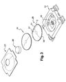
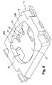
- FIGS 1 to 4 show a dual-action electrical switch 10 which is here, with no limitation being implied, shown in the form of a separate unit which is intended in particular to be fixed by welding to a PCB 12 (Printed Circuit Board), four parts of which are illustrated in the Figures.
- PCB 12 Printed Circuit Board
- the electrical switch 10 is generally symmetrical in design with respect to the median vertical and longitudinal plane PVML indicated in Figure 4 .
- the switch 10 consists essentially of a seat, or casing 14, which has the general shape of a rectangular parallelepiped and is produced by being moulded from electrically insulating plastic material.
- the casing 14 is in particular delimited by its upper horizontal face 16 and by its lower horizontal face 18.
- the casing 14 comprises a housing 20 which is open vertically upwards in the upper face 16 and which is delimited by a plane horizontal base 22, and by a concave cylindrical vertical side wall 23.
- the housing 20 houses at least partially the folded movable contact element 26, whilst the actuating element, or pusher 28, here extends vertically above the plane of the upper face 16.
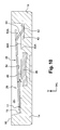
- the housing 20 also houses an upper dome 24 with a known general shape in the form of a spherical cap which is an upper dome with a sudden change of state which is interposed vertically between the actuator and the movable contact element 26, which provides a tactile sensation as a result of a sudden change of state when the second switching path is established but does not participate, from the point of view of electrical conductivity, in the establishment of the electrical switching paths.
- the dome 24 is not necessarily made from metal.
- the switch In the assembled position of the components, the switch is covered by a closing sealing film 21 which ensures a sealing closure of the top of the housing 20 and to which the pusher 28 is fixed by adhesive bonding.
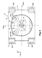
- the casing 14 is overmoulded around cut-out and folded metal strips illustrated in detail in Figure 7 in order to form the fixed contacts and the associated connecting terminals.
- the switch 10 thus comprises, in the base of the housing 20, a first and a second fixed peripheral contact 30A and 30B, each of which is independently connected electrically to the outside by an associated connecting terminal 32A, 32B which is designed so as to be able to be connected electrically to a corresponding track formed opposite the upper part of the printed circuit board 12.
- Each fixed peripheral contact 30A, 30B is arranged close to the vertical side wall 23 of the housing 20 and it takes the form of a circular chip which is here formed so that it projects vertically in such a way that its free upper horizontal face 34A, 34B extends above the plane of the upper horizontal face formed by the base 22 of the housing 20.
- the switch comprises a third fixed central contact 36 which is a shared fixed contact connected electrically to two other electrical connecting terminals 38A and 38B which are in turn intended to be connected to corresponding conductive tracks on the printed circuit board 12.
- the fixed central contact 36 is also produced in the form of a circular chip, the upper face 40 of which extends in a horizontal plane at a height, relative to the plane base 22, which is slightly lower than that of the upper faces 34A and 34B.
- a cavity 42 is provided, in the base of the housing 20, for positioning the folded movable contact element 26 at an angle, extends vertically downwards in a hollow and is integrally moulded from insulating plastic material.
- the cavity 42 is centred, relative to the plane PVML, between the two fixed contacts 30A and 30B.
- the base of the housing 20 comprises a bearing step 19 for the movable contact element 26 which projects vertically upwards and which is integrally moulded from insulating plastic material.
- the bearing step 19 is itself centred relative to the plane PVML and its upper plane horizontal face 17 is in the same plane as the upper faces 34A and 34B of the fixed peripheral contacts 30A and 30B.
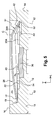
- the housing 20 receives and positions the movable contact element 26 in an initial raised rest position.
- the movable contact element 26 overall has the form of a dome folded about a chord.
- the movable contact element 26 here, like the upper dome 24, takes the form of a spherical cap with a continuous structure which is, for example, made from metal by being curved and which is delimited at its lower part by a peripheral lower circular edge 54.
- the movable contact element 26 also comprises an upper domed central section which is delimited by a convex upper face 27.
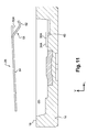
- the movable contact element 26 is, in its stable rest state, folded about a chord or fold C in such a way that all those points belonging to a section of the outer peripheral edge 54 which are situated radially opposite the central axis relative to the chord C are offset vertically downwards relative to the general plane in which the edge 54 extends.
- the movable contact element 26 thus comprises a folded part 51 in the sense of the invention, the lower free end of which, here virtually a point, is offset vertically downwards relative to the plane of the lower edge.
- the movable contact element 26 thus comprises an end point 52 of the downwardly folded part, which is the lowest vertically situated point relative to the plane of the lower edge 54.
- the point 52 cooperating with the cavity 42 effects an angular positioning of the movable contact element 26 about the central axis VA.
- the movable contact element 26 is thus positioned angularly in the housing 20, with play, in particular so that it cannot rotate in the housing and that its movements are limited to the deforming and tilting movements which will be described below, when it is deformed elastically.
- the dimensions, and in particular the external diameter, of the movable contact element 26 are such that it is housed at least partially and positioned in the housing 20.
- the movable contact element 26 with a known general design, in particular for creating a tactile effect when it is deformed elastically with a sudden change of state, is electrically conductive at least on its lower and inner concave face.
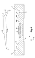
- the first pressing force exerted on the movable contact element 26, via the upper triggering dome 24, causes a first elastic deformation of the movable contact element 26 which is deformed, overall about the chord or fold C and counter to its inherent elasticity, in order to "resume” a "conventional" form similar to that of the upper triggering dome 24 in which all the points of the lower edge all extend substantially in the same lower plane, the continuous lower edge moreover being horizontal as a result of a simultaneous tilting effect of the movable contact element 26.
- the movable contact element 26 On completion of this first deformation, the movable contact element 26 then occupies a lowered position in which the corresponding points of its lower electrically conductive edge simultaneously bear with electrical contact against the coplanar upper faces 34A, 34B of the fixed peripheral contacts 30A and 30B.
- the movable contact element 26 is thus displaced from its initial raised rest position illustrated in Figure 5 towards its final lowered switching position in which its annular peripheral edge 54 bears against the two first fixed peripheral contacts 30A, 30B in order to establish the first electrical switching path between these contacts, and hence between the terminals 32A and 32B.
- the movable contact element 26 On completion of the first actuating phase, the movable contact element 26 is substantially “flat” and is situated in a “conventional” position in which it bears in a horizontal plane via its lower peripheral annular zone, or lower edge, in order to then allow its "conventional" sudden change of state.
- the user causes, in a known fashion, the simultaneous elastic deformation of the upper triggering dome 24 and of the movable contact element 26 and their sudden change of state.
- the lower conductive face of the central part of the movable contact element 26 comes into electrical contact with the upper face 40 of the fixed central contact 36.
- this deformation then establishes the second electrical switching path between the fixed central contact 36 and the fixed peripheral contacts 30A and 30B, in other words between the connecting terminals 38A, 38B and 32A, 32B.
- the first actuating travel is equal to approximately 0.1 mm with a force of 1 Newton
- the second actuating travel is equal to approximately 0.2 mm with an actuating force equal to 2.5 Newtons, for a triggering element 24 with a diameter equal to 2 mm.
- chord or fold C is situated at a distance of approximately 0.7 mm from the centre of the folded movable contact element 26.
- the extra upper triggering dome 24, with a conventional unfolded design, makes it possible, in a known fashion, to increase the value of the different elastic restoring forces and the tactile sensation but it does not participate in the establishment of the electrical switching path to the extent that its upper position, bearing against the upper face of the folded movable contact element 26, prevents any participation or cooperation with the fixed contacts.
- the different fixed contacts could belong directly to a rigid or flexible printed circuit board.
- the invention is also not limited to two fixed peripheral contacts. Indeed, it is, for example, possible to provide a third fixed contact (not shown) which is electrically independent from the two fixed peripheral contacts 30A and 30B, which is arranged in the base 43 of the cavity 42 and which is connected to the outside by an associated connecting terminal which is designed such that it can be connected electrically to a corresponding track formed opposite the upper part of the printed circuit board 12.
- the movable contact element 26 is thus permanently in electrical contact with this third fixed electrical contact - which does not belong to the two first switching paths - and, on completion of the second deformation phase, the movable contact element 26 simultaneously establishes two electrical switching paths, the second path mentioned above and a third between this extra fixed contact and the fixed central contact 36.
- the angular positioning of the movable contact element can alternatively be effected not by the lowest point 52 but, for example, by an angular positioning tab which can be integrally formed by cutting and folding and which is received in a cavity or a notch provided for this purpose.
- the movable contact element 26 here is in the form of a metal plate that has been cut out and bended and has a continuous structure with an electrically conductive plane lower face 54.
- the general contour of the plate which forms the movable contact element 26 complements overall the concave internal profile of the housing 20.
- the plate which forms the movable contact element 26 comprises a peripheral edge in the form of a circular section, like the movable contact element 26 in the first embodiment.
- the plate which forms the movable contact element 26 comprises a tab 51 which is cut out and folded vertically downwards and thus extends below the general plane of the plate.
- the folded tab 51 is shaped with a convexity which is oriented vertically downwards and it thus delimits a transverse line 52 for bearing against the face 43 of the base of the housing 42 in which the free end of the folded tab 51 is received.
- the folded tab 51 for bearing and angular positioning of the plate which forms the movable contact element 26 extends between two flanges 53A and 53B, each of which is a movable contact flange which is capable of coming into electrical contact with the upper face 34A, 34B of the opposite fixed peripheral contact 30A, 30B, on completion of the phase of the deformation of the tab 51 and displacement, by tilting, of the movable contact plate 26.
- the central zone 27 of the plate which is analogous to the central zone of the upper convex face 27 of the movable contact element 26 in the first embodiment, is a solid portion, the lower electrically conductive face of which extends opposite the upper face 40 of the fixed central contact 36.
- the upper triggering dome 24 which is delimited by a circular or annular peripheral edge, permanently bears against corresponding zones of each of the two flanges 53A and 53B, and of the plate which forms the movable contact element 26.
- the actuating element 28 acts indirectly on the plate which forms the movable contact element 26, via the upper triggering dome 24 which has a considerably greater rigidity than the plate which forms the movable contact 26 with its deformable tab 51.
- the actuating element 28 and the dome 24 cause the deformation of the tab 51 and hence the tilting, by the angle alpha, of the plate which forms the movable contact element 26 with a view to establishing the first switching path.
- the additional action at the centre of the triggering element 24 causes its sudden change of state, such that its central portion then strikes the opposite central zone 27 of the plate which forms the movable contact element 26 which is deformed so that, after a very short travel, it comes to bear with electrical contact against the upper face 40 of the fixed central contact 36, and thus establishes the second electrical switching path.
- the plate which forms the movable contact element 26 has no cutout or central recess, it has a high degree of rigidity which is especially important for making it possible to produce a switch with very small dimensions, in particular when the general diameter of the movable contact element 26 and of the triggering dome 24 is less than or equal to 2 millimetres.
- the design according to the invention which has just been described takes up a particularly small amount of space, both vertically and laterally, and it moreover makes it possible to produce, with a same "lower part", in other words with a same casing or seat 14, a single-action electrical switch by placing in the housing 20 a conventional triggering dome analogous to the triggering dome 24 which is then initially at rest in electrical contact via its lower edge with the two fixed peripheral contacts 30A and 30B, or alternatively an electrical switch according to the invention with two electrical switching paths established successively by using a movable contact element 26 in the form of a folded dome.
- the invention is not limited to a switch actuated by a vertical pusher but can also be applied in the case of lateral actuation with transfer of the movement along the vertical axis.
Landscapes
- Push-Button Switches (AREA)
- Contacts (AREA)
Applications Claiming Priority (1)
| Application Number | Priority Date | Filing Date | Title |
|---|---|---|---|
| FR1054617A FR2961340B1 (fr) | 2010-06-11 | 2010-06-11 | Commutateur electrique a effet tactile a double action |
Publications (2)
| Publication Number | Publication Date |
|---|---|
| EP2395529A2 true EP2395529A2 (fr) | 2011-12-14 |
| EP2395529A3 EP2395529A3 (fr) | 2012-09-19 |
Family
ID=43430657
Family Applications (1)
| Application Number | Title | Priority Date | Filing Date |
|---|---|---|---|
| EP11168346A Withdrawn EP2395529A3 (fr) | 2010-06-11 | 2011-06-01 | Commutateur électrique à effet tactile à double action |
Country Status (4)
| Country | Link |
|---|---|
| US (1) | US20110303520A1 (fr) |
| EP (1) | EP2395529A3 (fr) |
| CN (1) | CN102299018A (fr) |
| FR (1) | FR2961340B1 (fr) |
Cited By (2)
| Publication number | Priority date | Publication date | Assignee | Title |
|---|---|---|---|---|
| CN105336527A (zh) * | 2014-07-14 | 2016-02-17 | 富士康(昆山)电脑接插件有限公司 | 多方向开关装置 |
| CN111316392A (zh) * | 2017-10-30 | 2020-06-19 | 阿尔卑斯阿尔派株式会社 | 按压开关 |
Families Citing this family (23)
| Publication number | Priority date | Publication date | Assignee | Title |
|---|---|---|---|---|
| JP5447344B2 (ja) * | 2010-11-11 | 2014-03-19 | ミツミ電機株式会社 | スイッチ |
| JP1487382S (fr) * | 2013-03-26 | 2016-12-19 | ||
| JP2014212066A (ja) * | 2013-04-19 | 2014-11-13 | ミツミ電機株式会社 | スイッチ |
| FR3020956B1 (fr) | 2014-05-19 | 2021-09-24 | Commissariat Energie Atomique | Dispositif medical cutane comprenant un moyen de controle amovible du type connecteur electrique. |
| CN105261506B (zh) * | 2014-07-14 | 2018-03-06 | 富士康(昆山)电脑接插件有限公司 | 按压式开关 |
| USD809467S1 (en) | 2015-03-23 | 2018-02-06 | Citizen Electronics Co., Ltd. | Switch |
| US10139856B2 (en) * | 2016-05-25 | 2018-11-27 | Lg Electronics Inc. | Accessory assembly |
| US10204513B2 (en) | 2016-05-25 | 2019-02-12 | Lg Electronics Inc. | Accessory having a communication function for Internet of Things |
| US10111345B2 (en) | 2016-05-25 | 2018-10-23 | Lg Electronics Inc. | Sound output apparatus and hub for communication network |
| US10149080B2 (en) | 2016-05-25 | 2018-12-04 | Lg Electronics Inc. | Method of manufacturing sound output apparatus and method of manufacturing grille for the apparatus |
| US10110974B2 (en) | 2016-05-25 | 2018-10-23 | Lg Electronics Inc. | Accessory having a communication function for internet of things |
| US9990002B2 (en) | 2016-05-25 | 2018-06-05 | Lg Electronics Inc. | Sound output apparatus and hub for communication network |
| US10097640B2 (en) | 2016-05-25 | 2018-10-09 | Lg Electronics Inc. | Accessory having a communication function for internet of things |
| US10146255B2 (en) | 2016-05-25 | 2018-12-04 | Lg Electronics Inc. | Accessory communication device |
| US10139857B2 (en) | 2016-05-25 | 2018-11-27 | Lg Electronics Inc. | Accessory |
| US10356499B2 (en) | 2016-05-25 | 2019-07-16 | Lg Electronics Inc. | Artificial intelligence sound output apparatus, hub for communication network, method of manufacturing the apparatus, and grille for the apparatus |
| US9992036B2 (en) | 2016-05-25 | 2018-06-05 | Lg Electronics Inc. | Sound output apparatus and hub for communication network |
| US10440456B2 (en) | 2016-05-25 | 2019-10-08 | Lg Electronics Inc. | Artificial intelligence sound output apparatus, hub for communication network, and method of manufacturing the apparatus and grille for the apparatus |
| US10755876B2 (en) * | 2016-09-13 | 2020-08-25 | Panasonic Intellectual Property Management Co., Ltd. | Push switch |
| TWI696101B (zh) * | 2018-08-10 | 2020-06-11 | 致伸科技股份有限公司 | 表面固定型開關及具有表面固定型開關的觸控板模組與電子計算機 |
| USD956704S1 (en) * | 2020-12-04 | 2022-07-05 | Citizen Electronics Co., Ltd. | Push switch |
| CN112599368A (zh) * | 2020-12-08 | 2021-04-02 | 西安精密机械研究所 | 一种导通机构以及分离信号发生器 |
| WO2023157843A1 (fr) * | 2022-02-16 | 2023-08-24 | アルプスアルパイン株式会社 | Dispositif de commutation |
Citations (6)
| Publication number | Priority date | Publication date | Assignee | Title |
|---|---|---|---|---|
| US4359614A (en) | 1981-09-24 | 1982-11-16 | Illinois Tool Works Inc. | Miniature two-level pushbutton switch |
| US4385218A (en) | 1981-04-21 | 1983-05-24 | Matsushita Electric Industrial Co., Ltd. | Electric switch |
| US4659881A (en) | 1986-01-27 | 1987-04-21 | Eastman Kodak Company | Multidome multistage switch assembly |
| US5564560A (en) | 1995-06-07 | 1996-10-15 | Garmin Corporation | Dual function button |
| US5898147A (en) | 1997-10-29 | 1999-04-27 | C & K Components, Inc. | Dual tact switch assembly |
| US6498312B1 (en) | 1999-07-19 | 2002-12-24 | Alcatel | Two-pressure switch |
Family Cites Families (10)
| Publication number | Priority date | Publication date | Assignee | Title |
|---|---|---|---|---|
| US3996429A (en) * | 1975-04-18 | 1976-12-07 | Northern Electric Company Limited | Multi-contact push-button switch having plural prestressed contact members designed to provide plural circuit simultaneous switching inputs |
| US6492602B2 (en) * | 2000-02-10 | 2002-12-10 | Alps Electric Co., Ltd. | Two-position pushbutton switch |
| US6271487B1 (en) * | 2000-03-21 | 2001-08-07 | Itt Manufacturing Enterprises, Inc. | Normally open extended travel dual tact switch assembly with sequential actuation of individual switches |
| JP4121730B2 (ja) * | 2001-01-19 | 2008-07-23 | 富士通コンポーネント株式会社 | ポインティングデバイス及び携帯型情報機器 |
| JP2004193047A (ja) * | 2002-12-13 | 2004-07-08 | Matsushita Electric Ind Co Ltd | 押圧用突起付可動接点体 |
| JP4088577B2 (ja) * | 2003-10-16 | 2008-05-21 | ホシデン株式会社 | プッシュオンスイッチ用可動接点およびプッシュオンスイッチ |
| JP4171713B2 (ja) * | 2004-03-23 | 2008-10-29 | ホシデン株式会社 | プッシュオンスイッチ |
| JPWO2005124805A1 (ja) * | 2004-06-15 | 2008-04-17 | 日本航空電子工業株式会社 | ドーム接点およびそれを用いた多段動作電気スイッチ |
| KR101111457B1 (ko) * | 2006-02-06 | 2012-02-21 | 엘지전자 주식회사 | 키패드 및 그를 적용한 이동단말기와 키입력 처리방법 |
| FR2915021B1 (fr) * | 2007-04-12 | 2009-08-21 | Itt Mfg Enterprises Inc | Interrupteur electronique comportant une feuille elastique de positionnement horizontal du poussoir |
-
2010
- 2010-06-11 FR FR1054617A patent/FR2961340B1/fr active Active
-
2011
- 2011-06-01 EP EP11168346A patent/EP2395529A3/fr not_active Withdrawn
- 2011-06-08 US US13/155,982 patent/US20110303520A1/en not_active Abandoned
- 2011-06-10 CN CN2011101550575A patent/CN102299018A/zh active Pending
Patent Citations (6)
| Publication number | Priority date | Publication date | Assignee | Title |
|---|---|---|---|---|
| US4385218A (en) | 1981-04-21 | 1983-05-24 | Matsushita Electric Industrial Co., Ltd. | Electric switch |
| US4359614A (en) | 1981-09-24 | 1982-11-16 | Illinois Tool Works Inc. | Miniature two-level pushbutton switch |
| US4659881A (en) | 1986-01-27 | 1987-04-21 | Eastman Kodak Company | Multidome multistage switch assembly |
| US5564560A (en) | 1995-06-07 | 1996-10-15 | Garmin Corporation | Dual function button |
| US5898147A (en) | 1997-10-29 | 1999-04-27 | C & K Components, Inc. | Dual tact switch assembly |
| US6498312B1 (en) | 1999-07-19 | 2002-12-24 | Alcatel | Two-pressure switch |
Cited By (4)
| Publication number | Priority date | Publication date | Assignee | Title |
|---|---|---|---|---|
| CN105336527A (zh) * | 2014-07-14 | 2016-02-17 | 富士康(昆山)电脑接插件有限公司 | 多方向开关装置 |
| CN105336527B (zh) * | 2014-07-14 | 2019-03-22 | 富士康(昆山)电脑接插件有限公司 | 多方向开关装置 |
| CN111316392A (zh) * | 2017-10-30 | 2020-06-19 | 阿尔卑斯阿尔派株式会社 | 按压开关 |
| CN111316392B (zh) * | 2017-10-30 | 2022-02-22 | 阿尔卑斯阿尔派株式会社 | 按压开关 |
Also Published As
| Publication number | Publication date |
|---|---|
| US20110303520A1 (en) | 2011-12-15 |
| CN102299018A (zh) | 2011-12-28 |
| EP2395529A3 (fr) | 2012-09-19 |
| FR2961340B1 (fr) | 2013-06-28 |
| FR2961340A1 (fr) | 2011-12-16 |
Similar Documents
| Publication | Publication Date | Title |
|---|---|---|
| EP2395529A2 (fr) | Commutateur électrique à effet tactile à double action | |
| US20140110237A1 (en) | Push switch | |
| US6794589B2 (en) | Multiple electrical switch arrangement | |
| US7368672B2 (en) | Push-on switch | |
| KR20060055582A (ko) | 돔 접점 및 그것을 사용한 다단동작 전기 스위치 | |
| US9012796B2 (en) | Thin electrical switch | |
| US4156802A (en) | Electrical switch assembly | |
| US9508502B2 (en) | Push button switch having a curved deformable contact element | |
| EP1225607A3 (fr) | Contact en forme de dôme | |
| EP2363872B1 (fr) | Commutateur électrique à effet à double action | |
| KR890001357B1 (ko) | 다련(多連)스위치 | |
| EP2019403B1 (fr) | Commutateur électrique à voies de commutation multiples | |
| EP1198811B1 (fr) | Commutateur electrique a element de rotation unique et actionneur axial | |
| EP1049122B1 (fr) | Appareil de commutation avec commande pivotante | |
| US10068725B2 (en) | Touch-action electric switch with pre-load stroke | |
| JP2000353456A (ja) | 多方向スイッチ | |
| US6396014B1 (en) | Device to amplify the movement of an operating button of a switch | |
| JP2002313189A (ja) | 多方向スイッチ | |
| JP2002313188A (ja) | 多方向スイッチ | |
| JP3682062B1 (ja) | 多方向スイッチ | |
| JP2011090948A (ja) | 押圧スイッチ | |
| JP4687245B2 (ja) | プッシュオンスイッチ | |
| JP2004055343A (ja) | 押釦スイッチ | |
| JP4416700B2 (ja) | 多接点入力装置 | |
| JP2009206042A (ja) | 多段動作スイッチ用可動接点 |
Legal Events
| Date | Code | Title | Description |
|---|---|---|---|
| AK | Designated contracting states |
Kind code of ref document: A2 Designated state(s): AL AT BE BG CH CY CZ DE DK EE ES FI FR GB GR HR HU IE IS IT LI LT LU LV MC MK MT NL NO PL PT RO RS SE SI SK SM TR |
|
| AX | Request for extension of the european patent |
Extension state: BA ME |
|
| PUAI | Public reference made under article 153(3) epc to a published international application that has entered the european phase |
Free format text: ORIGINAL CODE: 0009012 |
|
| PUAL | Search report despatched |
Free format text: ORIGINAL CODE: 0009013 |
|
| AK | Designated contracting states |
Kind code of ref document: A3 Designated state(s): AL AT BE BG CH CY CZ DE DK EE ES FI FR GB GR HR HU IE IS IT LI LT LU LV MC MK MT NL NO PL PT RO RS SE SI SK SM TR |
|
| AX | Request for extension of the european patent |
Extension state: BA ME |
|
| RIC1 | Information provided on ipc code assigned before grant |
Ipc: H01H 13/64 20060101ALI20120816BHEP Ipc: H01H 13/44 20060101AFI20120816BHEP |
|
| RAP1 | Party data changed (applicant data changed or rights of an application transferred) |
Owner name: COACTIVE TECHNOLOGIES, LLC |
|
| 17P | Request for examination filed |
Effective date: 20130304 |
|
| STAA | Information on the status of an ep patent application or granted ep patent |
Free format text: STATUS: THE APPLICATION IS DEEMED TO BE WITHDRAWN |
|
| 18D | Application deemed to be withdrawn |
Effective date: 20150106 |