EP2395173A1 - Water runoff device, in particular for draining rainwater from the roof of a building - Google Patents
Water runoff device, in particular for draining rainwater from the roof of a building Download PDFInfo
- Publication number
- EP2395173A1 EP2395173A1 EP11168913A EP11168913A EP2395173A1 EP 2395173 A1 EP2395173 A1 EP 2395173A1 EP 11168913 A EP11168913 A EP 11168913A EP 11168913 A EP11168913 A EP 11168913A EP 2395173 A1 EP2395173 A1 EP 2395173A1
- Authority
- EP
- European Patent Office
- Prior art keywords
- tubular wall
- fixed
- plate
- movable
- wall
- Prior art date
- Legal status (The legal status is an assumption and is not a legal conclusion. Google has not performed a legal analysis and makes no representation as to the accuracy of the status listed.)
- Granted
Links
- XLYOFNOQVPJJNP-UHFFFAOYSA-N water Substances O XLYOFNOQVPJJNP-UHFFFAOYSA-N 0.000 title claims abstract description 24
- 239000012528 membrane Substances 0.000 claims abstract description 25
- 230000002093 peripheral effect Effects 0.000 claims abstract description 13
- 230000000694 effects Effects 0.000 claims description 3
- 238000009434 installation Methods 0.000 claims description 3
- 230000000295 complement effect Effects 0.000 description 17
- 238000007789 sealing Methods 0.000 description 7
- 239000011324 bead Substances 0.000 description 4
- 239000000463 material Substances 0.000 description 4
- 229910052751 metal Inorganic materials 0.000 description 3
- 239000002184 metal Substances 0.000 description 3
- 238000010438 heat treatment Methods 0.000 description 2
- BASFCYQUMIYNBI-UHFFFAOYSA-N platinum Chemical compound [Pt] BASFCYQUMIYNBI-UHFFFAOYSA-N 0.000 description 2
- 239000010426 asphalt Substances 0.000 description 1
- 230000006835 compression Effects 0.000 description 1
- 238000007906 compression Methods 0.000 description 1
- 230000008878 coupling Effects 0.000 description 1
- 238000010168 coupling process Methods 0.000 description 1
- 238000005859 coupling reaction Methods 0.000 description 1
- 238000009826 distribution Methods 0.000 description 1
- 238000004519 manufacturing process Methods 0.000 description 1
- 229910052697 platinum Inorganic materials 0.000 description 1
- 230000001105 regulatory effect Effects 0.000 description 1
- 239000003566 sealing material Substances 0.000 description 1
- 238000004513 sizing Methods 0.000 description 1
- 238000003466 welding Methods 0.000 description 1
Images


Classifications
-
- E—FIXED CONSTRUCTIONS
- E04—BUILDING
- E04D—ROOF COVERINGS; SKY-LIGHTS; GUTTERS; ROOF-WORKING TOOLS
- E04D13/00—Special arrangements or devices in connection with roof coverings; Protection against birds; Roof drainage; Sky-lights
- E04D13/04—Roof drainage; Drainage fittings in flat roofs, balconies or the like
- E04D13/0404—Drainage on the roof surface
- E04D13/0409—Drainage outlets, e.g. gullies
- E04D2013/0427—Drainage outlets, e.g. gullies with means for controlling the flow in the outlet
-
- E—FIXED CONSTRUCTIONS
- E04—BUILDING
- E04D—ROOF COVERINGS; SKY-LIGHTS; GUTTERS; ROOF-WORKING TOOLS
- E04D13/00—Special arrangements or devices in connection with roof coverings; Protection against birds; Roof drainage; Sky-lights
- E04D13/04—Roof drainage; Drainage fittings in flat roofs, balconies or the like
- E04D13/0404—Drainage on the roof surface
- E04D13/0409—Drainage outlets, e.g. gullies
- E04D2013/0436—Drainage outlets, e.g. gullies with sealing means
Definitions
- the present invention relates to the field of devices for the evacuation of rainwater, in particular roofs of buildings and terraces.
- Such studs are manufactured specifically for each roof or terrace, adapting the dimensions of the through openings mainly depending on the roof surface or terrace to be equipped and the rainfall of the place where the studs are located.
- manufacturers must have a range of pads to meet the needs, resulting in complex and expensive management of manufacturing, inventory and commercial distribution networks.
- the present invention aims to provide a more suitable water evacuation device.
- a rainwater flow device for installation on a receiving wall, in particular a roof of a building.
- this flow device comprises a plate having a passage; an exhaust duct whose upper end is connected to the edge of said passage of the plate; a fixed tubular wall of which a lower part is connected to said plate and which has at least one flow opening, said passage of the plate being inside this fixed tubular wall; a shutter movable relative to said fixed tubular wall so as to create an adjustable flow passage of the water through the flow opening of said fixed tubular wall and a flexible membrane which extends under said platen and beyond the peripheral edge of the latter.
- users have a flow device in the form of a kit that can be installed directly on a site via the membrane and can be adjusted on site, so as to adapt its flow rate to circumstances of the site.
- the section of the passage is adjustable by rotation and / or translation, possibly vertical, of the movable shutter relative to the fixed member, or a combination of both.
- the device may comprise means for indexing the position of the movable shutter relative to the fixed tubular wall, in different adjustment positions.
- the movable shutter may comprise a movable tubular wall placed on one side of the fixed tubular wall adjacent and cooperating with the fixed tubular wall so as to be guided by the latter and held in different adjustment positions with respect to this wall fixed tubular.
- the movable tubular wall may have at least one through opening, the movable tubular wall being movable relative to the fixed tubular wall so as to create an adjustable flow passage of water when the through opening of the wall fixed tubular and the through opening of the movable tubular wall are at least partly in coincidence.
- the upper edge of the fixed tubular wall and that of the movable tubular wall may have one of the indexing notches and the other a lateral tongue adapted to be engaged respectively in said notches.
- the fixed tubular wall may have a plurality of openings distributed around its periphery and the movable tubular wall has a plurality of openings distributed around its periphery, able to be placed at least partly in coincidence so as to create a plurality of adjustable passages. flow of water.
- the fixed tubular wall and the plate can be in one piece.
- the flexible membrane can be fixed under the plate.
- the flexible membrane may have an annular portion adjacent to a passage, the annular portion being sealed between an upper end of the exhaust duct and a mounting ring.
- the device may comprise an outer mounting ring enclosing the annular portion of the membrane against the end of the discharge duct and an inner mounting ring mounted in the end of the discharge duct, these mounting rings having flanges between which are taken platinum and the flexible membrane.
- the device may comprise an outer mounting ring enclosing the annular portion of the membrane against the end of the discharge duct and having a collar, the plate comprising an inner mounting ring mounted in the end of the discharge duct, the flexible membrane being taken between the flange of the outer mounting ring and the plate.
- the device may comprise a peripheral wall located outside and at a distance from the fixed tubular wall and a lower part of which is fixed on said plate.
- the device may comprise a peripheral wall located outside and at a distance from the fixed tubular wall, cooperating with guide means and a lower part of which may bear on the plate and move away from it under the effect of a float.
- the device may comprise upper stops limiting the stroke of the peripheral wall.
- the movable vertical wall may have a vertical slot and, on either side of this slot, vertical edges facing away from each other, provided with fixing means.
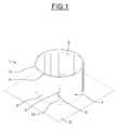
- a device 1 for evacuating rainwater for example galvanized sheet metal, comprises a horizontal plate 2, for example square, which has a circular central hole 3, and a lower cylindrical vertical duct 4 whose upper edge, folded outwardly, is fixed on the edge of the hole 3, for example by a weld seam or spot welded, for example tightly.
- the evacuation device 1 further comprises a fixed cylindrical vertical wall 5, for example cylindrical, extending upwards, whose diameter is greater than the diameter of the duct 4 and whose lower edge is fixed on the upper face. of the horizontal plate 2, concentrically to the conduit 4, for example by an internal weld bead.
- the lower edge of the fixed vertical wall 5 is located between the passage determined by the lower duct 4 and the peripheral edge of the plate 2.
- the fixed vertical wall 5 has a plurality of through openings 6, which are for example of rectangular shapes extended upwards, of identical sections and regularly distributed peripherally.
- the evacuation device 1 further comprises a movable shutter 7 which, according to the example shown, comprises a cylindrical vertical tubular wall 8, placed around the fixed vertical wall 5, adjacent and bearing on the upper face. of the horizontal plate 2, so as to be rotatable relative to the fixed vertical wall 5.
- the mobile vertical wall 8 could be arranged inside the fixed vertical wall 5, the cord of welding of the fixed vertical wall 5 on the plate 2 can then be outside.
- the movable vertical wall 8 the height of which corresponds approximately to that of the fixed vertical wall 5, has a plurality of through-openings 9, which are, for example, rectangular shapes extending upwards, of identical sections and regularly distributed peripherally.
- the through openings 9 of the movable vertical wall 8 and the through openings 6 of the fixed vertical wall 5 are of approximately the same dimensions.
- the movable vertical wall 8 can be displaced in rotation with respect to the fixed vertical wall 5 which guides it, so as to create a plurality of adjustable water flow passages 10, whose sections are adjustable, when the through openings 9 of the movable vertical wall 8 and the through openings 6 of the fixed vertical wall 5 are at least partly in coincidence.
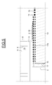
- the upper edge of the movable vertical wall 8 may have, as illustrated in particular on the figures 1 and 3 , a plurality of notches 11 offset peripherally and the upper edge of the fixed vertical wall 5 may have, as illustrated in particular on the figures 1 and 4 , a folding tongue 12 which can be engaged in the indexing notches 11, respectively.
- the through openings 6 of the fixed vertical wall 5 may be five in number
- the through openings 9 of the movable vertical wall 8 may be ten in number
- the indexing notches may be ten in number. so that there are ten adjustment positions corresponding to ten widths different from the adjustable flow passages 10, determined ten different sections of the adjustable water flow passages.
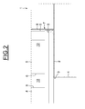
- the evacuation device 1 can be installed on a flat wall or reception slab 13 of a roof 14, or a terrace, for example covered with an outer sealing layer 15, for example of a bituminous material or other waterproof material, and having a vertical hole 16 in which is installed a vertical discharge pipe 17 of the rainwater, having an upper end collar 17a, annular, embedded in the sealing layer 15.
- the lower vertical duct 4 is engaged in the discharge duct 17 until the lower face of the plate 2 is placed on the outer sealing layer 15 of the roof 14. Then, a piece of sealing 18, for example also in a bitumen material, on the periphery of the upper face of the plate 2 and on the sealing layer 15, which is fixed for example by heating or other means of bonding. The evacuation device 1 is then fixed. Additional fastening means or other fastening means could be used.
- the rotational position of the movable vertical wall 8 with respect to the fixed vertical wall 5 is adjusted in a predetermined adjustment position, in particular as a function of the surface of the roof 14, or of the terrace , to equip, the rainfall of the place and the number of evacuation devices provided on the roof, or any other regulatory constraints, so as to create calibrated flow passages 10 of determined dimensions. Then, fold down the folding tongue 12 in the indexing notch 11 corresponding.
- the rainwater recovered on the roof 14 can flow through the calibrated flow passages 10, from the outside to the inside of the walls 5 and 8, at a calibrated flow rate, and be evacuated by the vertical duct 4 and then through the exhaust duct 17.
- the actual value of the flow rate depends on the height of the water level on the roof 14 with respect to the flow passages 10 and the maximum flow rate for the selected sections of the passages. 10, is approximately reached when the height of the water level is at or above the upper edges of the flow passages 10. In addition, for safety, when the water level reaches or passes above the height of the walls 5 and 8, the water flows directly into the latter towards the evacuation 17.
- the evacuation device 1 constitutes an adjustable flow restrictor, which can be installed on roofs or terraces of different surfaces located in different pluviometries, the fixed vertical wall 5 with its openings 6 and the movable vertical wall 8 with its openings 9 constituting a flow control means.
- the evacuation device 1 could be equipped, prior to its installation, with an annular flexible membrane bonded to the lower face of the plate 2 and protruding at the periphery of the latter and / or a flexible membrane shaped annular glued to the upper face of the plate 2 and protruding at the periphery thereof, integrating on or in the outer sealing layer 15 of the roof 14.
- a rainwater discharge device 20 comprises a horizontal plate 21 which has a circular peripheral edge and a central hole 22 whose edge is on and is coupled to the upper end of a lower cylindrical vertical conduit 23 by means that will be described later.
- the evacuation device 20 comprises a cylindrical fixed vertical tubular wall 24, whose lower edge is fixed on the plate 22, concentrically, for example by an internal weld bead.
- the evacuation device 20 further comprises a cylindrical movable vertical wall 25, placed around the fixed vertical wall 24, adjacent and bearing on the plate 22.
- the fixed vertical wall 24 and the movable vertical wall 25 can be configured as the fixed vertical wall 5 and the movable vertical wall 8 of the evacuation device 1 and respectively have a plurality of openings 26 and a plurality of openings 27 for creating flow passages 28 adjustable by rotation of the movable vertical wall 25 relative to the fixed vertical wall 24, as well as, for indexing purposes, a plurality of notches 29 and a folding tongue 30.
- the evacuation device 20 further comprises a horizontal flexible membrane 31, for example a sealing material, especially a bituminous material, which extends under the plate 21 and is contiguous thereto and extends beyond Beyond the peripheral edge of the plate 21.
- the flexible membrane 31 has a central passage whose cylindrical edge 32 is attached to the outer end of the upper portion of the conduit 23.
- an outer ring 33 enclosing the cylindrical edge 32 of the flexible membrane 31 against the outer end portion of the duct 23 and an inner ring 34 applied against the inner end of the conduit 23.
- the outer ring 33 and the inner ring 34 have peripheral flanges 35 and 35 which take between them the horizontal portion of the plate adjacent to its central passage 22 and the horizontal portion of the membrane 31 adjacent its cylindrical edge 32.
- the embodiment of the above coupling can be obtained by implementing compression tools, furthermore ensuring that the end portion of the duct 23, the cylindrical edge 32 of the flexible membrane 31, the ring 33 and the inner ring 34 form an annular bead 35, for example inwardly.
- the evacuation device 20 can be installed on a roof 36, or a terrace, provided with a discharge duct 37, in a manner equivalent to the evacuation device 1.
- the duct 23 extends in the duct 37
- the flexible membrane 31 is placed on a sealing layer 38 of the roof and can be fixed thereto by heating, in a manner known per se.
- an evacuation device 20A differs from the evacuation device 20 mainly in that the fixed vertical wall 24 is fixed on the plate 21 by an external weld bead and the movable vertical wall is disposed inside the the fixed vertical wall 24 and bears on the plate 21.
- an evacuation device 20B differs from the evacuation device 20 or 20A mainly in that the plate 21, the fixed vertical wall 24 and the inner ring 34 form a single piece 39 that can be obtained from a sidewall of sheet metal, the flange 36 no longer exists. Nevertheless, on the one hand, the plate 21 and the fixed vertical wall 24 could form a single piece and the inner ring 34 provided with its flange 36 could be reported as described above. On the other hand, the plate 21 and the inner ring 34 could form a single piece and the fixed vertical wall 24 could be reported as previously described, the flange 36 no longer exist.
- an evacuation device 40 comprises, around a fixed vertical wall 41, equivalent to the fixed vertical wall of any of the evacuation devices described above, a mobile vertical wall 42 which has a vertical slot 43 and, on either side of this slot, vertical edges 44 and 45 vis-à-vis extending outwardly, the movable vertical wall 42 is also configured equivalent to the movable vertical walls of the previous examples.
- the movable vertical wall 42 After having adjusted the movable vertical wall 42 with respect to the fixed vertical wall 41 as previously described, it is then possible to fix the vertical flanges 44 and 45 between them, for example by means of bolts or rivets, not shown, passing through holes 46. arranged through them.
- the sizing may be such that when the vertical edges 44 and 45 are brought together, the movable vertical wall 42 encloses the fixed vertical wall 41.
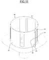
- an evacuation device 50 differs from the evacuation devices described above in that around and away from fixed and movable walls 51 and 52 installed on a plate 53, there is further provided a complementary tubular vertical wall 54, for example cylindrical, whose lower edge is fixed on the upper face of this plate 53, sealingly.
- the evacuation device 50 being installed on a roof or terrace as described above, the complementary vertical wall 54 constitutes a water retention obstacle on the roof or terrace around this complementary vertical wall 54.
- an evacuation device 60 differs from the evacuation device 50 described with reference to the figures 12 and 13 in that it comprises a complementary vertical wall 61 which is no longer fixed but which has a lower edge that can bear on an annular seal 63 fixed on a plate 62.
- the evacuation device 60 is equipped with vertical guide bars 64, for example four in number, which are placed inside the complementary vertical wall 61, at a short distance and distributed peripherally, and whose lower ends are fixed. on the plate 62.
- the complementary vertical wall 61 is provided with a float 65, for example annular, located at a distance above the plate 62.
- the evacuation device 60 being installed on a roof or terrace as described above, the vertical wall complementary 61, bearing on the annular seal 63, constitutes a water retention obstacle on the roof or the terrace around this complementary vertical wall 61.
- the complementary vertical wall 61 rises under the effect of the float and the water flows under the complementary vertical wall 61, towards the annular space 66 separating fixed and movable walls 67 and 68 and the complementary vertical wall 61 and flows through calibrated adjustable passages 69 created through the fixed and movable walls 51 and 52 as previously described to be evacuated.
- the upper ends 64a of the vertical bars 64 may be bent outward to extend above the upper edge of the complementary vertical wall 61, thereby forming upper stops, such that the complementary vertical wall 61 is vertically movable between on the one hand the seal 63 carried by the plate 62 and the ends 65a bent of the guide bars 65.
- the present invention is not limited to the examples described above.
- the openings in the fixed and movable walls could be of different shapes, for example round, oval, triangular or diamond-shaped.
- the fixed and mobile walls could be of different shapes and heights.
- Other evacuation devices could be obtained by combining the different structures described differently.
- the movable vertical wall being rotational, this wall could be adjustable by vertical movement to adjust the maximum flow rate.
- Many other embodiments are possible, without departing from the scope defined by the appended claims.
Abstract
Description
La présente invention concerne le domaine des dispositifs servant à l'évacuation de l'eau de pluie, en particulier des toits des bâtiments et des terrasses.The present invention relates to the field of devices for the evacuation of rainwater, in particular roofs of buildings and terraces.
Généralement, les dalles plates de toits et les terrasses entourées de rebords présentent des trous d'écoulement de l'eau de pluie qui est dirigée vers un réseau d'évacuation par des canalisations.Generally, flat roof slabs and terraces surrounded by rims have rainwater drainage holes which are directed to a drainage network through pipes.
Pour éviter que le réseau d'évacuation ne soit engorgé et ne déborde, il est connu d'équiper les toits et les terrasses de plots cylindriques verticaux en saillie, généralement en tôle, qui entourent les trous d'écoulement et qui présentent des ouvertures traversantes de telle sorte qu'il se produit une limitation du débit de l'eau évacuée.In order to prevent the drainage network from being clogged and overflowing, it is known to equip the roofs and terraces with vertical cylindrical studs, generally made of sheet metal, which surround the drainage holes and which have through openings such that there is a limitation of the flow of the discharged water.
De tels plots sont fabriqués spécifiquement pour chaque toit ou terrasse, en adaptant les dimensions des ouvertures traversantes principalement en fonction de la surface du toit ou de la terrasse à équiper et de la pluviométrie du lieu où les plots se trouvent. Ainsi, les fabricants doivent disposer d'une gamme de plots permettant de répondre aux besoins, ce qui entraîne une gestion complexe et coûteuse des fabrications, des stocks et des réseaux de distribution commerciale.Such studs are manufactured specifically for each roof or terrace, adapting the dimensions of the through openings mainly depending on the roof surface or terrace to be equipped and the rainfall of the place where the studs are located. Thus, manufacturers must have a range of pads to meet the needs, resulting in complex and expensive management of manufacturing, inventory and commercial distribution networks.
Par ailleurs, les documents
La présente invention a pour but de proposer un dispositif d'évacuation d'eau plus adapté aux besoins.The present invention aims to provide a more suitable water evacuation device.
Selon un mode de réalisation, il est proposé un dispositif d'écoulement d'eau de pluie destiné à être installé sur une paroi de réception, en particulier un toit d'un bâtiment.According to one embodiment, there is provided a rainwater flow device for installation on a receiving wall, in particular a roof of a building.
Selon l'invention, ce dispositif d'écoulement comprend une platine présentant un passage ; un conduit d'évacuation dont une extrémité supérieure est reliée au bord dudit passage de la platine ; une paroi tubulaire fixe dont une partie inférieure est reliée à ladite platine et qui présente au moins une ouverture d'écoulement, ledit passage de la platine étant à l'intérieur de cette paroi tubulaire fixe ; un obturateur mobile par rapport à ladite paroi tubulaire fixe de façon à créer un passage réglable d'écoulement de l'eau au travers de l'ouverture d'écoulement de ladite paroi tubulaire fixe et une membrane souple qui s'étend sous ladite platine et au-delà du bord périphérique de cette dernière.According to the invention, this flow device comprises a plate having a passage; an exhaust duct whose upper end is connected to the edge of said passage of the plate; a fixed tubular wall of which a lower part is connected to said plate and which has at least one flow opening, said passage of the plate being inside this fixed tubular wall; a shutter movable relative to said fixed tubular wall so as to create an adjustable flow passage of the water through the flow opening of said fixed tubular wall and a flexible membrane which extends under said platen and beyond the peripheral edge of the latter.
Ainsi, les utilisateurs disposent d'un dispositif d'écoulement se présentant sous la forme d'un kit pouvant être installé directement sur un site par l'intermédiaire de la membrane et pouvant être réglé sur le site, de façon à adapter son débit aux circonstances du site.Thus, users have a flow device in the form of a kit that can be installed directly on a site via the membrane and can be adjusted on site, so as to adapt its flow rate to circumstances of the site.
Selon des variantes simples de réalisation, la section du passage est réglable par rotation et/ou par translation, éventuellement verticale, de l'obturateur mobile par rapport à l'organe fixe, ou une combinaison des deux.According to simple variants, the section of the passage is adjustable by rotation and / or translation, possibly vertical, of the movable shutter relative to the fixed member, or a combination of both.
Le dispositif peut comprendre des moyens d'indexation de la position de l'obturateur mobile par rapport à la paroi tubulaire fixe, en différentes positions de réglage.The device may comprise means for indexing the position of the movable shutter relative to the fixed tubular wall, in different adjustment positions.
L'obturateur mobile peut comprendre une paroi tubulaire mobile placée d'un côté de la paroi tubulaire fixe de façon adjacente et coopérant avec la paroi tubulaire fixe de façon à être guidée par cette dernière et maintenue en différentes positions de réglage par rapport à cette paroi tubulaire fixe.The movable shutter may comprise a movable tubular wall placed on one side of the fixed tubular wall adjacent and cooperating with the fixed tubular wall so as to be guided by the latter and held in different adjustment positions with respect to this wall fixed tubular.
La paroi tubulaire mobile peut présenter au moins une ouverture traversante, la paroi tubulaire mobile étant mobile par rapport à la paroi tubulaire fixe de façon à créer un passage réglable d'écoulement d'eau lorsque l'ouverture traversante de la paroi tubulaire fixe et l'ouverture traversante de la paroi tubulaire mobile sont au moins en partie en coïncidence.The movable tubular wall may have at least one through opening, the movable tubular wall being movable relative to the fixed tubular wall so as to create an adjustable flow passage of water when the through opening of the wall fixed tubular and the through opening of the movable tubular wall are at least partly in coincidence.
Le bord supérieur de la paroi tubulaire fixe et celui de la paroi tubulaire mobile peuvent présenter l'un des encoches d'indexation et l'autre une languette latérale apte à être engagée dans respectivement lesdites encoches.The upper edge of the fixed tubular wall and that of the movable tubular wall may have one of the indexing notches and the other a lateral tongue adapted to be engaged respectively in said notches.
La paroi tubulaire fixe peut présenter une pluralité d'ouvertures réparties selon sa périphérie et la paroi tubulaire mobile présente une pluralité d'ouvertures réparties selon sa périphérie, aptes à être placées au moins en partie en coïncidence de façon à créer une pluralité de passages réglables d'écoulement de l'eau.The fixed tubular wall may have a plurality of openings distributed around its periphery and the movable tubular wall has a plurality of openings distributed around its periphery, able to be placed at least partly in coincidence so as to create a plurality of adjustable passages. flow of water.
La paroi tubulaire fixe et la platine peuvent être d'une seule pièce.The fixed tubular wall and the plate can be in one piece.
La membrane souple peut être fixée sous la platine.The flexible membrane can be fixed under the plate.
La membrane souple peut présenter une partie annulaire adjacente à un passage, cette partie annulaire étant prise de façon étanche entre une extrémité supérieure du conduit d'évacuation et une bague de montage.The flexible membrane may have an annular portion adjacent to a passage, the annular portion being sealed between an upper end of the exhaust duct and a mounting ring.
Le dispositif peut comprendre une bague extérieure de montage enserrant la partie annulaire de la membrane contre l'extrémité du conduit d'évacuation et une bague intérieure de montage montée dans l'extrémité du conduit d'évacuation, ces bagues de montage présentant des collerettes entre lesquelles sont prises la platine et la membrane souple.The device may comprise an outer mounting ring enclosing the annular portion of the membrane against the end of the discharge duct and an inner mounting ring mounted in the end of the discharge duct, these mounting rings having flanges between which are taken platinum and the flexible membrane.
Le dispositif peut comprendre une bague extérieure de montage enserrant la partie annulaire de la membrane contre l'extrémité du conduit d'évacuation et présentant une collerette, la platine comprenant une bague intérieure de montage montée dans l'extrémité du conduit d'évacuation, la membrane souple étant prise entre la collerette de la bague extérieure de montage et la platine.The device may comprise an outer mounting ring enclosing the annular portion of the membrane against the end of the discharge duct and having a collar, the plate comprising an inner mounting ring mounted in the end of the discharge duct, the flexible membrane being taken between the flange of the outer mounting ring and the plate.
Le dispositif peut comprendre une paroi périphérique située à l'extérieur et à distance de la paroi tubulaire fixe et dont une partie inférieure est fixée sur ladite platine.The device may comprise a peripheral wall located outside and at a distance from the fixed tubular wall and a lower part of which is fixed on said plate.
Le dispositif peut comprendre une paroi périphérique située à l'extérieur et à distance de la paroi tubulaire fixe, coopérant avec des moyens de guidage et dont une partie inférieure peut venir en appui sur la platine et s'en écarter sous l'effet d'un flotteur.The device may comprise a peripheral wall located outside and at a distance from the fixed tubular wall, cooperating with guide means and a lower part of which may bear on the plate and move away from it under the effect of a float.
Le dispositif peut comprendre des butées supérieures limitant la course de la paroi périphérique.The device may comprise upper stops limiting the stroke of the peripheral wall.
La paroi verticale mobile peut présenter une fente verticale et, de part et d'autre de cette fente, des rebords verticaux en vis-à-vis s'étendant vers l'extérieur, munis de moyens de fixation.The movable vertical wall may have a vertical slot and, on either side of this slot, vertical edges facing away from each other, provided with fixing means.
Des dispositifs d'évacuation d'eau de pluie vont maintenant être décrits à titre d'exemples non limitatifs, illustrés par le dessin sur lequel :
- la
figure 1 représente une vue en perspective d'un dispositif d'évacuation ; - la
figure 2 représente une demi-coupe du dispositif d'évacuation de lafigure 1 ; - les
figures 3 et 4 représentent des développés à plat respectivement de parois fixe et mobile du dispositif d'évacuation de lafigure 1 ; - la
figure 5 représente une demi-coupe du dispositif d'évacuation de lafigure 1 , installé sur un toit ; - la
figure 6 représente une vue en perspective d'un autre dispositif d'évacuation ; - la
figure 7 représente une demi-coupe du dispositif d'évacuation de lafigure 6 ; - la
figure 8 représente une demi-coupe du dispositif d'évacuation de lafigure 1 , installé sur un toit ; - la
figure 9 représente une demi-coupe d'une variante de réalisation du dispositif d'évacuation desfigures 6 à 8 ; - la
figure 10 représente une demi-coupe d'une variante de réalisation du dispositif d'évacuation desfigures 6 à 9 ; - la
figure 11 représente une vue en perspective d'un autre dispositif d'évacuation ; - la
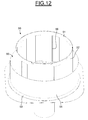
figure 12 représente une vue en perspective d'un autre dispositif d'évacuation ; - la
figure 13 représente une demi-coupe du dispositif d'évacuation de lafigure 12 ; - la
figure 14 représente une vue en perspective, partiellement en coupe, d'un autre dispositif d'évacuation ; et - la
figure 15 représente une demi-coupe du dispositif d'évacuation de lafigure 14 .
- the
figure 1 represents a perspective view of an evacuation device; - the
figure 2 represents a half-section of the evacuation device of thefigure 1 ; - the
Figures 3 and 4 represent developed flat respectively fixed and movable wall of the evacuation device of thefigure 1 ; - the
figure 5 represents a half-section of the evacuation device of thefigure 1 , installed on a roof; - the
figure 6 represents a perspective view of another evacuation device; - the
figure 7 represents a half-section of the evacuation device of thefigure 6 ; - the
figure 8 represents a half-section of the evacuation device of thefigure 1 , installed on a roof; - the
figure 9 represents a half-section of an alternative embodiment of the device for evacuatingFigures 6 to 8 ; - the
figure 10 represents a half-section of an alternative embodiment of the device for evacuatingFigures 6 to 9 ; - the
figure 11 represents a perspective view of another evacuation device; - the
figure 12 represents a perspective view of another evacuation device; - the
figure 13 represents a half-section of the evacuation device of thefigure 12 ; - the
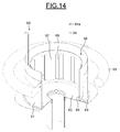
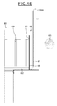
figure 14 represents a perspective view, partially in section, of another evacuation device; and - the
figure 15 represents a half-section of the evacuation device of thefigure 14 .
Selon une variante de réalisation illustrée sur les
Le dispositif d'évacuation 1 comprend en outre une paroi verticale tubulaire fixe 5, par exemple cylindrique, s'étendant vers le haut, dont le diamètre est plus grand que le diamètre du conduit 4 et dont le bord inférieur est fixé sur la face supérieure de la platine horizontale 2, concentriquement au conduit 4, par exemple par un cordon de soudure intérieur. Le bord inférieur de la paroi verticale fixe 5 est situé entre le passage déterminé par le conduit inférieur 4 et le bord périphérique de la platine 2.The
La paroi verticale fixe 5 présente une pluralité d'ouvertures traversantes 6, qui sont par exemple de formes rectangulaires étendues vers le haut, de sections identiques et régulièrement réparties périphériquement.The fixed
Le dispositif d'évacuation 1 comprend en outre un obturateur mobile 7 qui, selon l'exemple représenté, comprend une paroi verticale tubulaire 8, cylindrique, placée autour de la paroi verticale fixe 5, de façon adjacente, et en appui sur la face supérieure de la platine horizontale 2, de façon à être mobile en rotation par rapport à la paroi verticale fixe 5. Dans une variante, la paroi verticale mobile 8 pourrait être disposée à l'intérieur de la paroi verticale fixe 5, le cordon de soudure de la paroi verticale fixe 5 sur la platine 2 pouvant alors être à l'extérieur.The
La paroi verticale mobile 8, dont la hauteur correspond approximativement à celle de la paroi verticale fixe 5, présente une pluralité d'ouvertures traversantes 9, qui sont par exemple de formes rectangulaires étendues vers le haut, de sections identiques et régulièrement réparties périphériquement.The movable
Les ouvertures traversantes 9 de la paroi verticale mobile 8 et les ouvertures traversantes 6 de la paroi verticale fixe 5 sont approximativement de mêmes dimensions.The through
La paroi verticale mobile 8 peut être déplacée en rotation par rapport à la paroi verticale fixe 5 qui la guide, de façon à créer une pluralité de passages réglables d'écoulement d'eau 10, dont les sections sont réglables, lorsque les ouvertures traversantes 9 de la paroi verticale mobile 8 et les ouvertures traversantes 6 de la paroi verticale fixe 5 sont au moins en partie en coïncidence.The movable
En vue d'une indexation et du maintien de la paroi verticale mobile 8 par rapport à la paroi verticale fixe 5, en différentes positions de réglage, le bord supérieur de la paroi verticale mobile 8 peut présenter, comme illustré notamment sur les
A titre d'autre moyen d'indexation, on pourrait prévoir des repères sur les parois fixes et mobiles 5 et 8 et ces parois, placées en position réglée, pourraient être reliées par des vis ou des rivets les traversants.As another means of indexing, one could provide markings on the fixed and
Par exemple, les ouvertures traversantes 6 de la paroi verticale fixe 5 peuvent être au nombre de cinq, les ouvertures traversantes 9 de la paroi verticale mobile 8 peuvent être au nombre de dix et les encoches d'indexation peuvent être au nombre de dix, de telle sorte qu'il existe dix positions de réglage correspondant à dix largeurs différentes des passages d'écoulement réglables 10, déterminées dix sections différentes des passages réglables 10 d'écoulement d'eau.For example, the through
Comme illustré sur la
Pour cela, on engage le conduit vertical inférieur 4 dans le conduit d'évacuation 17 jusqu'à placer la face inférieure de la platine 2 sur la couche extérieure d'étanchéité 15 du toit 14. Puis, on place un morceau de couche d'étanchéité 18, par exemple aussi en une matière bitumée, sur la périphérie de la face supérieure de la platine 2 et sur la couche d'étanchéité 15, que l'on fixe par exemple par chauffage ou autre moyen de collage. Le dispositif d'évacuation 1 est alors fixé. Des moyens complémentaires de fixation ou d'autres moyens de fixation pourraient être utilisés.For this, the lower
Puis, on règle, à la main, la position en rotation de la paroi verticale mobile 8 par rapport à la paroi verticale fixe 5, dans une position de réglage préalablement déterminée, notamment en fonction de la surface du toit 14, ou de la terrasse, à équiper, de la pluviométrie du lieu et du nombre de dispositifs d'évacuation prévus sur le toit, ou toutes autres contraintes réglementaires, de façon à créer des passages d'écoulement 10 calibrés de dimensions déterminées. Puis, on rabat la languette rabattable 12 dans l'encoche d'indexation 11 correspondante.Then, by hand, the rotational position of the movable
Ainsi, l'eau de pluie récupérée sur le toit 14 peut s'écouler au travers des passages calibrés d'écoulement 10, de l'extérieur vers l'intérieur des parois 5 et 8, selon un débit calibré, et être évacuée par le conduit vertical 4 puis par le conduit d'évacuation 17.Thus, the rainwater recovered on the
On peut noter que la valeur réelle du débit dépend de la hauteur du niveau de l'eau sur le toit 14 par rapport aux passages d'écoulement 10 et que le débit maximum, pour les sections choisies des passages d'écoulement 10, est approximativement atteint lorsque la hauteur du niveau de l'eau est au niveau ou au-dessus des bords supérieurs des passages d'écoulement 10. De plus, par sécurité, lorsque le niveau de l'eau atteint ou passe au-dessus de la hauteur des parois 5 et 8, l'eau se déverse directement à l'intérieur de ces dernières vers l'évacuation 17.It may be noted that the actual value of the flow rate depends on the height of the water level on the
Il résulte de ce qui précède que le dispositif d'évacuation 1 constitue un limiteur de débit réglable, pouvant être installé sur des toits ou des terrasses de surfaces différentes situés dans des lieux de pluviométries différentes, la paroi verticale fixe 5 avec ses ouvertures 6 et la paroi verticale mobile 8 avec ses ouvertures 9 constituant un moyen de réglage du débit.It follows from the foregoing that the
Selon une variante de réalisation, le dispositif d'évacuation 1 pourrait être équipé, préalablement à son installation, d'une membrane souple annulaire collée sur la face inférieure de la platine 2 et dépassant à la périphérie de cette dernière et/ou d'une membrane souple en forme annulaire collée sur la face supérieure de la platine 2 et dépassant à la périphérie de cette dernière, s'intégrant sur ou dans la couche extérieure d'étanchéité 15 du toit 14.According to an alternative embodiment, the
Selon une variante de réalisation illustrée sur les
De façon équivalente au dispositif d'évacuation 1, le dispositif d'évacuation 20 comprend une paroi verticale fixe tubulaire 24, cylindrique, dont le bord inférieure est fixé sur la platine 22, concentriquement, par exemple par un cordon de soudure intérieur.Equivalently with the
Le dispositif d'évacuation 20 comprend en outre une paroi verticale mobile tubulaire 25, cylindrique, placée autour de la paroi verticale fixe 24, de façon adjacente, et en appui sur la platine 22.The
Pour constituer un moyen de réglage de débit, la paroi verticale fixe 24 et la paroi verticale mobile 25 peuvent être configurées comme la paroi verticale fixe 5 et la paroi verticale mobile 8 du dispositif d'évacuation 1 et présentent respectivement une pluralité d'ouvertures 26 et une pluralité d'ouvertures 27 permettant de créer des passages d'écoulement 28 réglables par rotation de la paroi verticale mobile 25 par rapport à la paroi verticale fixe 24, ainsi que, en vue d'une indexation, une pluralité d'encoches 29 et une languette rabattable 30.To constitute a flow control means, the fixed
Le dispositif d'évacuation 20 comprend en outre une membrane souple horizontale 31, par exemple en une matière d'étanchéité, notamment en une matière bitumeuse, qui s'étend sous la platine 21 et est accolée à cette dernière et s'étend au-delà du bord périphérique de la platine 21. La membrane souple 31 présente un passage central dont le bord 32, cylindrique, est accolé à la partie extérieure d'extrémité supérieure du conduit 23.The
Pour accoupler la platine 21 et la membrane souple 31 sur l'extrémité supérieure du conduit 23, par exemple de façon étanche, sont prévues une bague extérieure 33 enserrant le bord cylindrique 32 de la membrane souple 31 contre la partie extérieure d'extrémité du conduit 23 et une bague intérieure 34 appliquée contre la partie intérieure d'extrémité du conduit 23. En outre, la bague extérieure 33 et la bague intérieure 34 présentent des collerettes périphériques 35 et 35 qui prennent entre elles la partie horizontale de la platine adjacente à son passage central 22 et la partie horizontale de la membrane 31 adjacente à son bord cylindrique 32.To couple the
La réalisation de l'accouplement ci-dessus peut être obtenue en mettant en oeuvre des outils de compression, faisant en sorte, en outre, que la partie d'extrémité du conduit 23, le bord cylindrique 32 de la membrane souple 31, la bague extérieure 33 et la bague intérieure 34 forment un bourrelet annulaire 35, par exemple vers l'intérieur.The embodiment of the above coupling can be obtained by implementing compression tools, furthermore ensuring that the end portion of the
Comme illustré sur la
Selon une variante de réalisation illustrée sur la
Selon une variante de réalisation illustrée sur la
Selon une variante de réalisation illustrée sur la
Après avoir réglé la paroi verticale mobile 42 par rapport à la paroi verticale fixe 41 comme décrit précédemment, on peut alors fixer les rebords verticaux 44 et 45 entre eux, par exemple grâce à des boulons ou des rivets, non représentés, traversant des trous 46 aménagés au travers d'eux. Les dimensionnements peuvent être telles que lorsque les rebords verticaux 44 et 45 sont rapprochés, la paroi verticale mobile 42 enserre la paroi verticale fixe 41.After having adjusted the movable
Selon une variante de réalisation illustrée sur les
Le dispositif d'évacuation 50 étant installé sur un toit ou une terrasse comme décrit précédemment, la paroi verticale complémentaire 54 constitue un obstacle de rétention d'eau sur le toit ou la terrasse autour de cette paroi verticale complémentaire 54.The
Néanmoins, lorsque le niveau de l'eau sur le toit ou la terrasse atteint ou dépasse le bord supérieur de la paroi verticale complémentaire 54, l'eau déborde et se déverse dans l'espace annulaire 55 séparant les parois fixes et mobiles 51 et 52 et la paroi verticale complémentaire 54 puis s'écoule au travers des passages réglables calibrés 56 créés au travers des parois fixes et mobiles 51 et 52 comme décrit précédemment, pour être évacuée.Nevertheless, when the level of the water on the roof or terrace reaches or exceeds the upper edge of the complementary
Selon une variante de réalisation illustrée sur les
Le dispositif d'évacuation 60 est équipé de barres verticales de guidage 64, par exemple au nombre de quatre, qui sont placées à l'intérieur de la paroi verticale complémentaire 61, à faible distance et réparties périphériquement, et dont les extrémités inférieures sont fixées sur la platine 62.The
A l'extérieur, la paroi verticale complémentaire 61 est munie d'un flotteur 65, par exemple annulaire, situé à distance au-dessus de la platine 62.Outside, the complementary
Le dispositif d'évacuation 60 étant installé sur un toit ou une terrasse comme décrit précédemment, la paroi verticale complémentaire 61, en appui sur le joint annulaire 63, constitue un obstacle de rétention d'eau sur le toit ou la terrasse autour de cette paroi verticale complémentaire 61.The
Néanmoins, lorsque le niveau de l'eau sur le toit ou la terrasse atteint le flotteur 65 et monte, la paroi verticale complémentaire 61 monte sous l'effet du flotteur et l'eau s'écoule sous la paroi verticale complémentaire 61, vers l'espace annulaire 66 séparant des parois fixes et mobiles 67 et 68 et la paroi verticale complémentaire 61 puis s'écoule au travers des passages réglables calibrés 69 créés au travers des parois fixes et mobiles 51 et 52 comme décrit précédemment pour être évacuée.Nevertheless, when the level of the water on the roof or terrace reaches the
Quand le niveau de l'eau redescend, la paroi verticale complémentaire 61 redescend en appui sur le joint 63 et retient à nouveau l'eau.When the water level drops, the complementary
Pour limiter la course vers le haut de la paroi verticale complémentaire 61, les extrémités supérieures 64a des barres verticales 64 peuvent être coudées vers l'extérieur pour s'étendre au-dessus du bord supérieur de la paroi verticale complémentaire 61, en formant ainsi des butées supérieures, de telle sorte que la paroi verticale complémentaire 61 est mobile verticalement entre d'une part le joint 63 porté par la platine 62 et les extrémités 65a coudées des barres de guidage 65.To limit the upward travel of the complementary
La présente invention ne se limite pas aux exemples ci-dessus décrits. En particulier, les ouvertures aménagées dans les parois fixes et mobiles pourraient être de formes différentes, par exemple rondes, ovales, triangulaires ou en forme de losanges. Les parois fixes et mobiles pourraient être de formes et de hauteurs différentes. D'autres dispositifs d'évacuation pourraient être obtenus en combinant différemment les différentes structures décrites. Au lieu que la paroi verticale mobile soit réglage par rotation, cette paroi pourrait être réglable par déplacement vertical de façon à régler le débit maximum d'écoulement. Bien d'autres variantes de réalisation sont possibles, sans sortir du cadre défini par les revendications annexées.The present invention is not limited to the examples described above. In particular, the openings in the fixed and movable walls could be of different shapes, for example round, oval, triangular or diamond-shaped. The fixed and mobile walls could be of different shapes and heights. Other evacuation devices could be obtained by combining the different structures described differently. Instead of the movable vertical wall being rotational, this wall could be adjustable by vertical movement to adjust the maximum flow rate. Many other embodiments are possible, without departing from the scope defined by the appended claims.
Claims (17)
Applications Claiming Priority (1)
| Application Number | Priority Date | Filing Date | Title |
|---|---|---|---|
| FR1054659A FR2961230B1 (en) | 2010-06-11 | 2010-06-11 | WATER FLOW DEVICE, ESPECIALLY FOR EVACUATING RAIN WATER FROM A ROOF OF A BUILDING |
Publications (2)
| Publication Number | Publication Date |
|---|---|
| EP2395173A1 true EP2395173A1 (en) | 2011-12-14 |
| EP2395173B1 EP2395173B1 (en) | 2013-11-13 |
Family
ID=43466476
Family Applications (1)
| Application Number | Title | Priority Date | Filing Date |
|---|---|---|---|
| EP20110168913 Active EP2395173B1 (en) | 2010-06-11 | 2011-06-07 | Water runoff device, in particular for draining rainwater from the roof of a building |
Country Status (2)
| Country | Link |
|---|---|
| EP (1) | EP2395173B1 (en) |
| FR (1) | FR2961230B1 (en) |
Cited By (1)
| Publication number | Priority date | Publication date | Assignee | Title |
|---|---|---|---|---|
| FR3072107A1 (en) * | 2017-10-10 | 2019-04-12 | Gerard Iftissen | SEALING DEVICE FOR THE BUILDING, COMPRISING A CONDUIT AND A CONNECTING MEMBER |
Citations (7)
| Publication number | Priority date | Publication date | Assignee | Title |
|---|---|---|---|---|
| FR762406A (en) | 1933-10-16 | 1934-04-11 | Overflow drain cover for sinks, etc. | |
| DE1806527A1 (en) | 1968-11-02 | 1970-05-14 | Josam Mfg Co | Roof drainage with regulated flow |
| US3517813A (en) | 1968-09-16 | 1970-06-30 | Kunibert Thaler | Roof drain |
| US4400272A (en) | 1981-06-08 | 1983-08-23 | Logsdon Duane D | Drain grate with adjustable weirs |
| US6318397B1 (en) * | 1999-08-04 | 2001-11-20 | Donald G. Huber | Side port floor drain |
| CA2409056A1 (en) | 2002-10-21 | 2004-04-21 | Gabe Coscarella | Cleanout with drainage capabilities |
| EP1710365A1 (en) * | 2005-03-23 | 2006-10-11 | Odco | Sealing device for building constructions and method of its manufacture |
-
2010
- 2010-06-11 FR FR1054659A patent/FR2961230B1/en not_active Expired - Fee Related
-
2011
- 2011-06-07 EP EP20110168913 patent/EP2395173B1/en active Active
Patent Citations (7)
| Publication number | Priority date | Publication date | Assignee | Title |
|---|---|---|---|---|
| FR762406A (en) | 1933-10-16 | 1934-04-11 | Overflow drain cover for sinks, etc. | |
| US3517813A (en) | 1968-09-16 | 1970-06-30 | Kunibert Thaler | Roof drain |
| DE1806527A1 (en) | 1968-11-02 | 1970-05-14 | Josam Mfg Co | Roof drainage with regulated flow |
| US4400272A (en) | 1981-06-08 | 1983-08-23 | Logsdon Duane D | Drain grate with adjustable weirs |
| US6318397B1 (en) * | 1999-08-04 | 2001-11-20 | Donald G. Huber | Side port floor drain |
| CA2409056A1 (en) | 2002-10-21 | 2004-04-21 | Gabe Coscarella | Cleanout with drainage capabilities |
| EP1710365A1 (en) * | 2005-03-23 | 2006-10-11 | Odco | Sealing device for building constructions and method of its manufacture |
Cited By (4)
| Publication number | Priority date | Publication date | Assignee | Title |
|---|---|---|---|---|
| FR3072107A1 (en) * | 2017-10-10 | 2019-04-12 | Gerard Iftissen | SEALING DEVICE FOR THE BUILDING, COMPRISING A CONDUIT AND A CONNECTING MEMBER |
| WO2019073161A1 (en) * | 2017-10-10 | 2019-04-18 | Iftissen Gerard | Sealing device for construction, comprising a duct and connection member |
| EP3910127A1 (en) * | 2017-10-10 | 2021-11-17 | Gérard Iftissen | Sealing device for building, comprising a conduit and a connecting member |
| US11248378B2 (en) | 2017-10-10 | 2022-02-15 | Rikksen | Sealing device for construction, comprising a duct and connection member |
Also Published As
| Publication number | Publication date |
|---|---|
| FR2961230B1 (en) | 2017-02-24 |
| FR2961230A1 (en) | 2011-12-16 |
| EP2395173B1 (en) | 2013-11-13 |
Similar Documents
| Publication | Publication Date | Title |
|---|---|---|
| EP4071316B1 (en) | Drainage device provided with a fastening sleeve for construction, in particular a building roof or a terrace | |
| WO2017129747A1 (en) | Annular sealing ring between two ducts, in particular for construction | |
| EP2395173B1 (en) | Water runoff device, in particular for draining rainwater from the roof of a building | |
| FR3087461A1 (en) | DRAINAGE DEVICE FOR A CONSTRUCTION, IN PARTICULAR A ROOF OF A BUILDING OR A TERRACE | |
| KR102134641B1 (en) | Adjust height for raise ring manhole cover | |
| EP2930283A1 (en) | Tubular gooseneck for building | |
| EP3601861B1 (en) | Device for sealing between two coaxial ducts and assembly | |
| EP2845961B1 (en) | Building with a roof and an external cladding jointed | |
| FR2555284A1 (en) | Sealed joint and connection device for pipelines, especially sewerage installations | |
| FR2970269A1 (en) | Fireproof trap door installation unit, has connection and handling arm coupled to inner wall of frame and one of panels, where jacks are actuated for lifting or lowering panels simultaneously by constituting double-fire barrier | |
| EP0487422B1 (en) | Profile for the fixation of covering elements such as a cover on a concrete element such as a beam | |
| EP3061878B1 (en) | Device for collecting storm water | |
| FR2985529A1 (en) | Hydraulic gutter for use in drainage and storm water removal device on ground of e.g. shower room of building, has slit formed on upper face of upper rib, where longitudinal side of slit is opened in interior part of tube | |
| FR3080126A1 (en) | AVALOIR TO EVACUATE STAGNANTES STAGNANTES ON THE BALCONIES AND TERRACES AND DEVICE OF EVACUATION ASSOCIATED | |
| FR2981962A1 (en) | Railing shoe for use in safety railing for protecting e.g. roofer, performing repairing operations in e.g. roof, of building, has base plate fixed in tightened support on end of mast by sealed fixing unit that fixes base plate to mast | |
| CA1145572A (en) | Removable gutter for manholes and ducts | |
| FR2959250A1 (en) | Modular element for e.g. beam gutter, has female formations whose dimensions are slightly higher than that of male formations, so that interstices are formed between end faces with respect to formations mutually stacked with bodies | |
| FR3060621A1 (en) | REGARDING AVALER WITH A COUPLED TUBE | |
| FR2955876A1 (en) | DEVICE FOR FIXING SOLAR PANELS AND ROOF THUS EQUIPPED | |
| FR2701500A1 (en) | Manhole (inspection chamber) for an underground pipe, especially a sewage main | |
| FR2526461A1 (en) | WELL CELLAR, SAID VISIT | |
| EP2902555A1 (en) | Connecting part of a rainwater drainage line, inspection gallery for rainwater drainage lines and drainage assembly comprising said inspection gallery | |
| KR101073861B1 (en) | Sinking prevention having handhole | |
| EP2410094B1 (en) | Rain water tank | |
| FR3046783A1 (en) | SYSTEM FOR RECEIVING A BURNER CONTAINER |
Legal Events
| Date | Code | Title | Description |
|---|---|---|---|
| AK | Designated contracting states |
Kind code of ref document: A1 Designated state(s): AL AT BE BG CH CY CZ DE DK EE ES FI FR GB GR HR HU IE IS IT LI LT LU LV MC MK MT NL NO PL PT RO RS SE SI SK SM TR |
|
| AX | Request for extension of the european patent |
Extension state: BA ME |
|
| PUAI | Public reference made under article 153(3) epc to a published international application that has entered the european phase |
Free format text: ORIGINAL CODE: 0009012 |
|
| 17P | Request for examination filed |
Effective date: 20120416 |
|
| 17Q | First examination report despatched |
Effective date: 20120928 |
|
| GRAP | Despatch of communication of intention to grant a patent |
Free format text: ORIGINAL CODE: EPIDOSNIGR1 |
|
| INTG | Intention to grant announced |
Effective date: 20130527 |
|
| GRAS | Grant fee paid |
Free format text: ORIGINAL CODE: EPIDOSNIGR3 |
|
| GRAA | (expected) grant |
Free format text: ORIGINAL CODE: 0009210 |
|
| AK | Designated contracting states |
Kind code of ref document: B1 Designated state(s): AL AT BE BG CH CY CZ DE DK EE ES FI FR GB GR HR HU IE IS IT LI LT LU LV MC MK MT NL NO PL PT RO RS SE SI SK SM TR |
|
| REG | Reference to a national code |
Ref country code: GB Ref legal event code: FG4D Free format text: NOT ENGLISH |
|
| REG | Reference to a national code |
Ref country code: CH Ref legal event code: EP |
|
| REG | Reference to a national code |
Ref country code: AT Ref legal event code: REF Ref document number: 640656 Country of ref document: AT Kind code of ref document: T Effective date: 20131215 |
|
| REG | Reference to a national code |
Ref country code: IE Ref legal event code: FG4D Free format text: LANGUAGE OF EP DOCUMENT: FRENCH |
|
| REG | Reference to a national code |
Ref country code: DE Ref legal event code: R096 Ref document number: 602011003631 Country of ref document: DE Effective date: 20140109 |
|
| REG | Reference to a national code |
Ref country code: NL Ref legal event code: VDEP Effective date: 20131113 |
|
| REG | Reference to a national code |
Ref country code: AT Ref legal event code: MK05 Ref document number: 640656 Country of ref document: AT Kind code of ref document: T Effective date: 20131113 |
|
| REG | Reference to a national code |
Ref country code: LT Ref legal event code: MG4D |
|
| PG25 | Lapsed in a contracting state [announced via postgrant information from national office to epo] |
Ref country code: IS Free format text: LAPSE BECAUSE OF FAILURE TO SUBMIT A TRANSLATION OF THE DESCRIPTION OR TO PAY THE FEE WITHIN THE PRESCRIBED TIME-LIMIT Effective date: 20140313 Ref country code: FI Free format text: LAPSE BECAUSE OF FAILURE TO SUBMIT A TRANSLATION OF THE DESCRIPTION OR TO PAY THE FEE WITHIN THE PRESCRIBED TIME-LIMIT Effective date: 20131113 Ref country code: SE Free format text: LAPSE BECAUSE OF FAILURE TO SUBMIT A TRANSLATION OF THE DESCRIPTION OR TO PAY THE FEE WITHIN THE PRESCRIBED TIME-LIMIT Effective date: 20131113 Ref country code: LT Free format text: LAPSE BECAUSE OF FAILURE TO SUBMIT A TRANSLATION OF THE DESCRIPTION OR TO PAY THE FEE WITHIN THE PRESCRIBED TIME-LIMIT Effective date: 20131113 Ref country code: HR Free format text: LAPSE BECAUSE OF FAILURE TO SUBMIT A TRANSLATION OF THE DESCRIPTION OR TO PAY THE FEE WITHIN THE PRESCRIBED TIME-LIMIT Effective date: 20131113 Ref country code: NL Free format text: LAPSE BECAUSE OF FAILURE TO SUBMIT A TRANSLATION OF THE DESCRIPTION OR TO PAY THE FEE WITHIN THE PRESCRIBED TIME-LIMIT Effective date: 20131113 Ref country code: NO Free format text: LAPSE BECAUSE OF FAILURE TO SUBMIT A TRANSLATION OF THE DESCRIPTION OR TO PAY THE FEE WITHIN THE PRESCRIBED TIME-LIMIT Effective date: 20140213 |
|
| PG25 | Lapsed in a contracting state [announced via postgrant information from national office to epo] |
Ref country code: CY Free format text: LAPSE BECAUSE OF FAILURE TO SUBMIT A TRANSLATION OF THE DESCRIPTION OR TO PAY THE FEE WITHIN THE PRESCRIBED TIME-LIMIT Effective date: 20131113 Ref country code: AT Free format text: LAPSE BECAUSE OF FAILURE TO SUBMIT A TRANSLATION OF THE DESCRIPTION OR TO PAY THE FEE WITHIN THE PRESCRIBED TIME-LIMIT Effective date: 20131113 Ref country code: ES Free format text: LAPSE BECAUSE OF FAILURE TO SUBMIT A TRANSLATION OF THE DESCRIPTION OR TO PAY THE FEE WITHIN THE PRESCRIBED TIME-LIMIT Effective date: 20131113 Ref country code: RS Free format text: LAPSE BECAUSE OF FAILURE TO SUBMIT A TRANSLATION OF THE DESCRIPTION OR TO PAY THE FEE WITHIN THE PRESCRIBED TIME-LIMIT Effective date: 20131113 Ref country code: LV Free format text: LAPSE BECAUSE OF FAILURE TO SUBMIT A TRANSLATION OF THE DESCRIPTION OR TO PAY THE FEE WITHIN THE PRESCRIBED TIME-LIMIT Effective date: 20131113 |
|
| PG25 | Lapsed in a contracting state [announced via postgrant information from national office to epo] |
Ref country code: PT Free format text: LAPSE BECAUSE OF FAILURE TO SUBMIT A TRANSLATION OF THE DESCRIPTION OR TO PAY THE FEE WITHIN THE PRESCRIBED TIME-LIMIT Effective date: 20140313 |
|
| PG25 | Lapsed in a contracting state [announced via postgrant information from national office to epo] |
Ref country code: EE Free format text: LAPSE BECAUSE OF FAILURE TO SUBMIT A TRANSLATION OF THE DESCRIPTION OR TO PAY THE FEE WITHIN THE PRESCRIBED TIME-LIMIT Effective date: 20131113 |
|
| REG | Reference to a national code |
Ref country code: DE Ref legal event code: R097 Ref document number: 602011003631 Country of ref document: DE |
|
| PG25 | Lapsed in a contracting state [announced via postgrant information from national office to epo] |
Ref country code: PL Free format text: LAPSE BECAUSE OF FAILURE TO SUBMIT A TRANSLATION OF THE DESCRIPTION OR TO PAY THE FEE WITHIN THE PRESCRIBED TIME-LIMIT Effective date: 20131113 Ref country code: SK Free format text: LAPSE BECAUSE OF FAILURE TO SUBMIT A TRANSLATION OF THE DESCRIPTION OR TO PAY THE FEE WITHIN THE PRESCRIBED TIME-LIMIT Effective date: 20131113 Ref country code: CZ Free format text: LAPSE BECAUSE OF FAILURE TO SUBMIT A TRANSLATION OF THE DESCRIPTION OR TO PAY THE FEE WITHIN THE PRESCRIBED TIME-LIMIT Effective date: 20131113 Ref country code: RO Free format text: LAPSE BECAUSE OF FAILURE TO SUBMIT A TRANSLATION OF THE DESCRIPTION OR TO PAY THE FEE WITHIN THE PRESCRIBED TIME-LIMIT Effective date: 20131113 |
|
| PLBE | No opposition filed within time limit |
Free format text: ORIGINAL CODE: 0009261 |
|
| STAA | Information on the status of an ep patent application or granted ep patent |
Free format text: STATUS: NO OPPOSITION FILED WITHIN TIME LIMIT |
|
| PG25 | Lapsed in a contracting state [announced via postgrant information from national office to epo] |
Ref country code: DK Free format text: LAPSE BECAUSE OF FAILURE TO SUBMIT A TRANSLATION OF THE DESCRIPTION OR TO PAY THE FEE WITHIN THE PRESCRIBED TIME-LIMIT Effective date: 20131113 |
|
| 26N | No opposition filed |
Effective date: 20140814 |
|
| REG | Reference to a national code |
Ref country code: DE Ref legal event code: R097 Ref document number: 602011003631 Country of ref document: DE Effective date: 20140814 |
|
| REG | Reference to a national code |
Ref country code: DE Ref legal event code: R119 Ref document number: 602011003631 Country of ref document: DE |
|
| PG25 | Lapsed in a contracting state [announced via postgrant information from national office to epo] |
Ref country code: MC Free format text: LAPSE BECAUSE OF FAILURE TO SUBMIT A TRANSLATION OF THE DESCRIPTION OR TO PAY THE FEE WITHIN THE PRESCRIBED TIME-LIMIT Effective date: 20131113 Ref country code: LU Free format text: LAPSE BECAUSE OF FAILURE TO SUBMIT A TRANSLATION OF THE DESCRIPTION OR TO PAY THE FEE WITHIN THE PRESCRIBED TIME-LIMIT Effective date: 20140607 |
|
| REG | Reference to a national code |
Ref country code: CH Ref legal event code: PL |
|
| PG25 | Lapsed in a contracting state [announced via postgrant information from national office to epo] |
Ref country code: SI Free format text: LAPSE BECAUSE OF FAILURE TO SUBMIT A TRANSLATION OF THE DESCRIPTION OR TO PAY THE FEE WITHIN THE PRESCRIBED TIME-LIMIT Effective date: 20131113 |
|
| REG | Reference to a national code |
Ref country code: IE Ref legal event code: MM4A |
|
| REG | Reference to a national code |
Ref country code: DE Ref legal event code: R119 Ref document number: 602011003631 Country of ref document: DE Effective date: 20150101 |
|
| PG25 | Lapsed in a contracting state [announced via postgrant information from national office to epo] |
Ref country code: IT Free format text: LAPSE BECAUSE OF FAILURE TO SUBMIT A TRANSLATION OF THE DESCRIPTION OR TO PAY THE FEE WITHIN THE PRESCRIBED TIME-LIMIT Effective date: 20131113 Ref country code: LI Free format text: LAPSE BECAUSE OF NON-PAYMENT OF DUE FEES Effective date: 20140630 Ref country code: IE Free format text: LAPSE BECAUSE OF NON-PAYMENT OF DUE FEES Effective date: 20140607 Ref country code: DE Free format text: LAPSE BECAUSE OF NON-PAYMENT OF DUE FEES Effective date: 20150101 Ref country code: CH Free format text: LAPSE BECAUSE OF NON-PAYMENT OF DUE FEES Effective date: 20140630 |
|
| GBPC | Gb: european patent ceased through non-payment of renewal fee |
Effective date: 20150607 |
|
| PG25 | Lapsed in a contracting state [announced via postgrant information from national office to epo] |
Ref country code: MT Free format text: LAPSE BECAUSE OF FAILURE TO SUBMIT A TRANSLATION OF THE DESCRIPTION OR TO PAY THE FEE WITHIN THE PRESCRIBED TIME-LIMIT Effective date: 20131113 |
|
| PG25 | Lapsed in a contracting state [announced via postgrant information from national office to epo] |
Ref country code: GB Free format text: LAPSE BECAUSE OF NON-PAYMENT OF DUE FEES Effective date: 20150607 Ref country code: SM Free format text: LAPSE BECAUSE OF FAILURE TO SUBMIT A TRANSLATION OF THE DESCRIPTION OR TO PAY THE FEE WITHIN THE PRESCRIBED TIME-LIMIT Effective date: 20131113 |
|
| PG25 | Lapsed in a contracting state [announced via postgrant information from national office to epo] |
Ref country code: BG Free format text: LAPSE BECAUSE OF FAILURE TO SUBMIT A TRANSLATION OF THE DESCRIPTION OR TO PAY THE FEE WITHIN THE PRESCRIBED TIME-LIMIT Effective date: 20131113 Ref country code: GR Free format text: LAPSE BECAUSE OF FAILURE TO SUBMIT A TRANSLATION OF THE DESCRIPTION OR TO PAY THE FEE WITHIN THE PRESCRIBED TIME-LIMIT Effective date: 20140214 |
|
| PG25 | Lapsed in a contracting state [announced via postgrant information from national office to epo] |
Ref country code: BE Free format text: LAPSE BECAUSE OF FAILURE TO SUBMIT A TRANSLATION OF THE DESCRIPTION OR TO PAY THE FEE WITHIN THE PRESCRIBED TIME-LIMIT Effective date: 20140630 Ref country code: TR Free format text: LAPSE BECAUSE OF FAILURE TO SUBMIT A TRANSLATION OF THE DESCRIPTION OR TO PAY THE FEE WITHIN THE PRESCRIBED TIME-LIMIT Effective date: 20131113 Ref country code: HU Free format text: LAPSE BECAUSE OF FAILURE TO SUBMIT A TRANSLATION OF THE DESCRIPTION OR TO PAY THE FEE WITHIN THE PRESCRIBED TIME-LIMIT; INVALID AB INITIO Effective date: 20110607 |
|
| REG | Reference to a national code |
Ref country code: FR Ref legal event code: PLFP Year of fee payment: 6 |
|
| REG | Reference to a national code |
Ref country code: FR Ref legal event code: PLFP Year of fee payment: 7 |
|
| REG | Reference to a national code |
Ref country code: FR Ref legal event code: PLFP Year of fee payment: 8 |
|
| PG25 | Lapsed in a contracting state [announced via postgrant information from national office to epo] |
Ref country code: MK Free format text: LAPSE BECAUSE OF FAILURE TO SUBMIT A TRANSLATION OF THE DESCRIPTION OR TO PAY THE FEE WITHIN THE PRESCRIBED TIME-LIMIT Effective date: 20131113 |
|
| PG25 | Lapsed in a contracting state [announced via postgrant information from national office to epo] |
Ref country code: AL Free format text: LAPSE BECAUSE OF FAILURE TO SUBMIT A TRANSLATION OF THE DESCRIPTION OR TO PAY THE FEE WITHIN THE PRESCRIBED TIME-LIMIT Effective date: 20131113 |
|
| PGFP | Annual fee paid to national office [announced via postgrant information from national office to epo] |
Ref country code: FR Payment date: 20230329 Year of fee payment: 13 |