EP2395153B1 - Procédé et dispositif de fabrication de lamelles murales dans le sol - Google Patents
Procédé et dispositif de fabrication de lamelles murales dans le sol Download PDFInfo
- Publication number
- EP2395153B1 EP2395153B1 EP10006124A EP10006124A EP2395153B1 EP 2395153 B1 EP2395153 B1 EP 2395153B1 EP 10006124 A EP10006124 A EP 10006124A EP 10006124 A EP10006124 A EP 10006124A EP 2395153 B1 EP2395153 B1 EP 2395153B1
- Authority
- EP
- European Patent Office
- Prior art keywords
- drilling
- mixing tools
- carriage
- soil
- intermediate guide
- Prior art date
- Legal status (The legal status is an assumption and is not a legal conclusion. Google has not performed a legal analysis and makes no representation as to the accuracy of the status listed.)
- Active
Links
Images

Classifications
-
- E—FIXED CONSTRUCTIONS
- E02—HYDRAULIC ENGINEERING; FOUNDATIONS; SOIL SHIFTING
- E02D—FOUNDATIONS; EXCAVATIONS; EMBANKMENTS; UNDERGROUND OR UNDERWATER STRUCTURES
- E02D3/00—Improving or preserving soil or rock, e.g. preserving permafrost soil
- E02D3/12—Consolidating by placing solidifying or pore-filling substances in the soil
- E02D3/126—Consolidating by placing solidifying or pore-filling substances in the soil and mixing by rotating blades
-
- E—FIXED CONSTRUCTIONS
- E02—HYDRAULIC ENGINEERING; FOUNDATIONS; SOIL SHIFTING
- E02D—FOUNDATIONS; EXCAVATIONS; EMBANKMENTS; UNDERGROUND OR UNDERWATER STRUCTURES
- E02D5/00—Bulkheads, piles, or other structural elements specially adapted to foundation engineering
- E02D5/18—Bulkheads or similar walls made solely of concrete in situ
- E02D5/187—Bulkheads or similar walls made solely of concrete in situ the bulkheads or walls being made continuously, e.g. excavating and constructing bulkheads or walls in the same process, without joints
Definitions
- the invention relates firstly to a method for producing wall slats in a floor with at least two rod-shaped, parallel juxtaposed drilling and mixing tools, which at their bottom-side lower end each have a cutting device for removing soil material and along a tool rod mixing elements, wherein the Drilling and blending tools are drivably driven and sunk into the ground to create overlapping wellbores, the drilling and mixing tools being interconnected via a staging yoke, soil material removed from the cutters, fed a binder suspension, and mixed with the abraded soil material is mixed to a floor mortar, and after reaching a desired drilling depth, the drilling and mixing tools are withdrawn from the ground again and the soil mortar hardens to a wall plate, the drilling and mixing tools to ih the upper end driven by a drive carriage and guided linearly along a mast guide.
- the invention relates to a device for producing wall slats in a floor with at least two rod-shaped, parallel juxtaposed drilling and mixing tools, which have at their bottom-side lower end each have a cutting device for removing soil material and along a tool rod mixing elements, a mast with a mast guide, a drive slide with rotary drive for rotationally driving the drilling and mixing tools, wherein the drive carriage is guided and movable along the mast guide.
- a generic prior art for example, from the JP 7 071 030 A or the DE 102 38 646 B3 out.
- This known method can be very effective vertical Wall lamellae are created in the ground, which can form a vertical sealing or supporting wall by overlapping.
- the individual wall lamellae must be created in an exact position to each other.
- drilling and mixing tools which have a corresponding length.
- the risk of drilling and mixing tools sinking into the ground increases. In this way, unwanted gaps between the individual wall slats can arise, so that the sealing function of the entire wall is impaired.
- the risk of bleeding in this known method can be further increased if an axial force is applied by a carrier device to the drilling and mixing tools for accelerated Abteufen.
- drilling devices are from the EP 1 486 616 A1 , of the JP 2006 348644 A or the EP 0411560 A2 known.
- the invention has for its object to provide a method and an apparatus with which wall slats can be created efficiently and nevertheless with high accuracy.
- the inventive method according to claim 1 is particularly characterized in that up to a first drilling depth at least the drilling and mixing tools are supported via an intermediate guide slide which is guided along the mast guide that the connection of the drilling and mixing tools is released to the intermediate guide carriage, and that then the bore is further sunk.
- a basic idea of the invention is not to guide and move the drilling and mixing tools by the drive slide at the upper end of the drilling and mixing tools along the mast, but to use at least one second slide, namely an intermediate guide slide. Through this intermediate guide carriage additional support in a central region of the drilling and mixing tools against the mast of the carrier device takes place.
- a connection between the intermediate guide carriage and the drilling and mixing tools is provided according to the invention, which connection is achieved when a first drilling depth is reached.
- drilling and mixing tools After loosening the drilling and mixing tools to the intermediate guide slide drilling and mixing tools can be further sunk by the drive slide. Since the drilling and mixing tools are already in the ground to a considerable extent in the created hole in the ground, the risk of buckling or running of the drilling and mixing tools is reduced by the surrounding soil.
- Another advantage of the invention is that the drilling and mixing tools run quieter overall and less impact. It is thus achieved a higher dimensional accuracy and better verticality of the wall elements to be created.
- the improved smoothness also reduces the wear on the drilling and mixing tools as well as their bearings and the drive.
- a preferred embodiment of the invention is that the connection to the intermediate guide carriage is released when it has reached a lower end position on the mast guide.
- On the mast guide can be provided as the lower end position an adjustable stop. It is given an exact position at which the connection to the intermediate guide carriage is released, and the Drilling and mixing tools without contact to the intermediate guide slide can be sunk to its full length.
- the drilling and mixing tools are connected to each other via a stiffening yoke, which is detachably connected via a coupling device with the intermediate guide carriage.
- the stiffening yoke has corresponding bearing sleeves, in which the respective tool rod is rotatably supported.
- a further improvement of the guide according to the invention is achieved in that the drilling and mixing tools are additionally guided directly above the soil surface by a guide sleeve.
- the guide sleeve corresponds approximately to the cross-sectional contour of the wall plate to be created and provides a contact guide to the radially projecting mixing elements on the drilling and mixing tools.
- connection to the intermediate guide carriage is closed again when retracting the drilling and mixing tools.
- an improved leadership and stiffening over the mast are also achieved in the retraction movement. This additional stiffening relieves the bearings of the drilling and mixing tools.
- connection to the intermediate guide carriage can be released or closed by hand. It is particularly advantageous according to the invention that the connection to the intermediate guide carriage is automatically released or closed without interrupting the drilling operation.
- This automatic loosening and closing of the connection can be achieved in a simple manner by providing simple mechanical coupling elements which, due to a corresponding limitation of the movement, separate from one another or are simply taken along again when they are retracted.
- the connection can be made non-positively and / or positively.
- energy-operated closure devices for example with adjusting springs or adjusting cylinders. In order to bring about the least possible resistance to the penetration of the drilling and mixing tools into the ground, only a single connection to an intermediate guide carriage is provided.
- the support takes place via a plurality of intermediate guide carriage.
- a first intermediate guide carriage can be released from the drilling and mixing tools at a first drilling depth, while a second intermediate guide carriage remains connected to the drilling and mixing tools for further support. This second connection is then released upon reaching a second larger drilling depth, so that only then the drilling and mixing tools can be sunk to the desired final depth.
- the inventive device for creating wall elements according to claim 7 is particularly characterized according to the invention in that on the mast below the drive carriage, an intermediate guide carriage is slidably guided and that a coupling device is provided, with which at least one drilling and mixing tool with the intermediate guide carriage detachably connected is.
- a coupling device is provided, with which at least one drilling and mixing tool with the intermediate guide carriage detachably connected is.
- the drilling and mixing tools are connected to each other via a stiffening yoke and that the stiffening yoke is releasably connected via the coupling device with the intermediate guide carriage.
- the intermediate guide carriage can stiffen over a single connection all parallel drilling and mixing tools.
- the drilling and mixing tools can be arranged in a row, which are arranged transversely to the longitudinal direction of a carrier vehicle or in the longitudinal direction to the longitudinal axis of the carrier vehicle.
- the coupling device can have one or more coupling elements.
- a preferred embodiment of the invention is that for applying an axial force of the drive carriage and / or the intermediate guide carriage are displaceably driven on the mast.
- the drive carriage is along the mast via a cable drive or linearly movable via an actuating cylinder.
- the drive slide also contains the rotary drive for the drilling and mixing tools as well as a flushing head for supplying the binder suspension via the tubular tool rod.
- a particularly efficient application of force in the axial direction down and / or above is achieved in that, in addition to the drive slide, the intermediate guide slide is also displaceably driven by a linear drive on the mast. In this way, in addition to the drive carriage, the axial force can also be exerted on the drilling and mixing tools at a second location, thereby further reducing the risk of buckling.
- the coupling device comprises a first coupling element and a second coupling element, which cooperate with one another for producing the releasable connection non-positively and / or positively.
- actively actuated actuators such as actuating cylinders, can be used for energy-actuated closing or opening the connection.
- the first coupling element has an upwardly or downwardly directed hook element and the second coupling element has a transverse bar.
- a downwardly directed hook element arranged on the intermediate guide carriage, while the crossbar is arranged as a second coupling element on the drilling and mixing tools to a corresponding bearing sleeve. Reached the intermediate guide carriage its lower end position at a predetermined stop, so the cross bar can proceed with the drilling and mixing tools in a simple manner down and introduced into the ground with.
- the second coupling element is not radially opposite the mixing elements on the tool bars.
- the first coupling element has a substantially rod-shaped element and the second coupling element has a recess matching the rod-shaped element.
- the rod-shaped element can be arranged in particular vertically and in a recess in engage a horizontal plate to form the connection.
- the coupling device can be designed in many other ways and, for example, bolts, bushings, sleeves or other carriers have, which force and / or interlock positively to produce and release the connection. In this case, additional locking mechanisms can be provided which ensure reliable closing or opening of the connection.
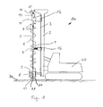
- a mast 2 is arranged in an approximately vertical position in a conventional manner.
- a drive carriage 12 is guided linearly movable.
- three parallel drilling and mixing tools 10 are rotatably supported on the drive carriage 12 and rotationally driven via individual rotary actuators 13.
- the drilling and mixing tools 10 each have a tool rod 5, at the lower end of a radially directed cutting device 31 is arranged for removing soil material.
- a suspension line 15 is connected via a flushing head 14, through which a binder suspension can be fed to an existing borehole through an internal cavity 25 in the tubular tool rod 5 up to an outlet opening 17 in the region of the cutting device 31.
- the tool bars 5 are arranged in a conventional manner as mixing elements conveyor coils 6 and mixing paddles 7 spaced from each other to mix the removed soil with the supplied binder suspension to a soil mortar in the created hole.
- a detachable connection 1 between the drilling and mixing tools 10 and an intermediate guide carriage 16 is arranged in the device 50 according to the invention, so that the tool bars 5 are additionally supported relative to the mast 2.
- the intermediate guide carriage 16 is guided along the mast 2, wherein the guide in the present embodiment takes place via the same mast guide 3 with rectangular guide rails, which is also provided for the drive carriage 12.
- the rectangular guide rails engage in correspondingly formed guide grooves 28 of the intermediate guide carriage 16.
- the drilling and mixing tools 10 are up to a first drilling depth on the drive carriage 12 and the intermediate guide slide 16 sunk into the ground 70. At this first drilling depth of the intermediate guide carriage 16 reaches its lower end position on the mast 2.
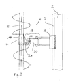
- a coupling device 19 with a first hook-shaped coupling element 20 which is secured to the intermediate guide carriage 16
- a second coupling element 21st which is attached to a rotary sleeve 18.
- the tool rod 5 is rotatably but axially fixed in each case.
- the second coupling element 21 has a transversely directed to the drilling direction crossbar 24, which is in positive and positive connection with the downwardly open, hook-shaped first coupling element 20.
- the intermediate guide carriage 16 Upon reaching the lower end position of the intermediate guide carriage 16, the intermediate guide carriage 16 remains in this end position, while the drilling and mixing tools 10 are further sunk by the drive carriage 12.
- the cross bar 24 moves in a simple manner from the downwardly open receiving the hook-shaped first coupling element 20.
- the drilling and mixing tools 10 can now be sunk by the drive carriage 12 to its final depth, in which the drive carriage 12 also its end position at the bottom Reached the end of the mast 2.
- the clutch could also be arranged vice versa, wherein the cross bar 24 is attached to the intermediate guide carriage 16 and the hook-shaped coupling element 21 to the drilling and mixing tools 10.
- the individual rotary sleeves 18 of the individual drilling and mixing tools 10 are welded together via connecting webs 23 so as to form a stiffening yoke 4.
- a second coupling element 21, each with a cross bar 24 is attached to the connecting webs 23.
- two first coupling elements 20 are provided opposite to the intermediate guide carriage 16.
- a lower stiffening yoke 9 is furthermore provided, which stiffens the parallel tool rods 5 against one another in a lower region in accordance with the stiffening yoke 4 already described. Furthermore, at the bottom of the mast 2 an oval guide sleeve 8 is arranged, whose inside has a guide contact with the outer periphery 30 of the drilling and mixing tools 10.
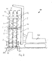
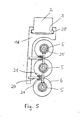
- the three drilling and mixing tools 10 are arranged in a line transverse to a longitudinal direction of the carrier device 40 and form a so-called cross-cultivation.
- a so-called longitudinal attachment provided in which the three drilling and mixing tools 10 are arranged in series in a direction to the longitudinal or direction of travel of the carrier device 40.
- Such a longitudinal attachment is especially useful for creating a sealing wall along a narrow dam.
- This longitudinal attachment according to the second device 60 according to the invention causes a corresponding change of the intermediate guide carriage 16 and the drive carriage 12 with the bar-shaped upper rotary guide 11. Otherwise, however, the arrangement and the proper operation of the second device 60 according to the arrangement and function of the first device 50 according to the invention the FIGS. 1 . 3 and 4 ,
Claims (11)
- Procédé de fabrication de lamelles murales dans un sol (70), avec au moins deux outils de forage et de mélange (10) en forme de tiges disposés parallèlement l'un à côté de l'autre, qui présentent chacun, à leur extrémité inférieure côté sol, un dispositif de coupe (31) pour extraire du matériau de sol et des organes de mélange (6, 7) le long d'une tige d'outil (5), dans lequel- pour réaliser des trous de forage se chevauchant, les outils de forage et de mélange (10) sont entraînés en rotation et enfoncés dans le sol (70), les outils de forage et de mélange (10) étant reliés entre eux par un lien de rigidification (4),- le matériau de sol est extrait par les dispositifs de coupe (31),- une suspension de liant est introduite et mélangée au matériau de sol extrait par les organes de mélange (6, 7) pour former un mortier de sol, et- après avoir atteint une profondeur de forage souhaitée, les outils de forage et de mélange (10) sont retirés du sol et le mortier de sol est durci en une lamelle murale,- dans lequel les outils de forage et de mélange (10) sont entraînés à leur extrémité supérieure par l'intermédiaire d'un chariot d'entraînement (12) et guidés linéairement le long d'un guide (3) de type mât,
caractérisé en ce que- le lien de rigidification (4) est relié de façon amovible à un chariot de guidage intermédiaire (16) par une liaison (1) avec un dispositif de couplage (19), chariot qui est guidé coulissant le long du guide (3) de type mât,- en ce que, jusqu'à une première profondeur de forage, les outils de forage et de mélange (10) sont supportés par le chariot de guidage intermédiaire (16),- en ce que la liaison (1) des outils de forage et de mélange (10) avec le chariot de guidage intermédiaire (16) est défaite, et- en ce qu'ensuite, le creusement du forage est poursuivi. - Procédé selon la revendication 1, caractérisé en ce que la liaison (1) avec le chariot de guidage intermédiaire (16) est défaite lorsque celui-ci a atteint la position inférieure finale sur le guide (3) de type mât.
- Procédé selon l'une des revendications 1 ou 2, caractérisé en ce que les outils de forage et de mélange (10) sont guidés en plus par une douille de guidage (8) directement au-dessus de la surface du sol.
- Procédé selon l'une des revendications 1 à 3, caractérisé en ce que, lors du retrait des outils de forage et de mélange (10), la liaison (1) avec le chariot de guidage intermédiaire (16) est refermée.
- Procédé selon l'une des revendications 1 à 4, caractérisé en ce que la liaison (1) avec le chariot de guidage intermédiaire (16) est défaite ou fermée automatiquement, sans interruption de l'opération de forage.
- Procédé selon l'une des revendications 1 à 5, caractérisé en ce qu'un support s'effectue par l'intermédiaire de plusieurs chariots de guidage intermédiaires (16).
- Dispositif pour réaliser des lamelles de mur dans un sol (70) avec- au moins deux outils de forage et de mélange (10) en forme de tiges disposés parallèlement l'un à côté de l'autre, qui présentent chacun, à leur extrémité inférieure côté sol, un dispositif de coupe (31) pour extraire du matériau de sol et des organes de mélange (6, 7) le long d'une tige d'outil (5), les outils de forage et de mélange (10) étant reliés entre eux par l'intermédiaire d'un lien de rigidification (4, 9),- un mât (2) avec un guide (3) de type mât, et- un chariot d'entraînement (12) avec entraînement rotatif (13) pour entraîner en rotation les outils de forage et de mélange (10), le chariot d'entraînement (12) étant guidé et mobile le long du guide (3) de type mât,
caractérisé en ce que- un chariot de guidage intermédiaire (16) est guidé mobile sur le mât (2) au-dessous du chariot d'entraînement (12), chariot qui est relié au lien de rigidification (4, 9) par une liaison (1) avec un dispositif de couplage (19), et- en ce que le lien de rigidification (4) peut, par l'intermédiaire du dispositif de couplage (19), être détaché du chariot de guidage intermédiaire (16) lors du creusement d'un forage. - Dispositif selon la revendication 7, caractérisé en ce que, pour appliquer une force axiale, le chariot d'entraînement (12) et/ou le chariot de guidage intermédiaire (16) est/sont entraîné(s) de manière mobile sur le mât (2).
- Dispositif selon l'une des revendications 7 ou 8, caractérisé en ce que le dispositif de couplage (19) présente un premier élément de couplage (20) et un deuxième élément de couplage (21), qui coopèrent par adhérence et/ou par engagement positif pour établir la liaison (1) amovible.
- Dispositif selon la revendication 9, caractérisé en ce que le premier élément de couplage (20) présente un élément formant crochet dirigé vers le haut ou vers le bas et le deuxième élément de couplage (21) présente une barre transversale (24).
- Dispositif selon la revendication 9, caractérisé en ce que le premier élément de couplage (20) présente un élément sensiblement en forme de barreau et le deuxième élément de couplage (21) un logement adapté à cet élément en forme de barreau.
Priority Applications (1)
| Application Number | Priority Date | Filing Date | Title |
|---|---|---|---|
| EP10006124A EP2395153B1 (fr) | 2010-06-11 | 2010-06-11 | Procédé et dispositif de fabrication de lamelles murales dans le sol |
Applications Claiming Priority (1)
| Application Number | Priority Date | Filing Date | Title |
|---|---|---|---|
| EP10006124A EP2395153B1 (fr) | 2010-06-11 | 2010-06-11 | Procédé et dispositif de fabrication de lamelles murales dans le sol |
Publications (2)
| Publication Number | Publication Date |
|---|---|
| EP2395153A1 EP2395153A1 (fr) | 2011-12-14 |
| EP2395153B1 true EP2395153B1 (fr) | 2013-03-27 |
Family
ID=43064679
Family Applications (1)
| Application Number | Title | Priority Date | Filing Date |
|---|---|---|---|
| EP10006124A Active EP2395153B1 (fr) | 2010-06-11 | 2010-06-11 | Procédé et dispositif de fabrication de lamelles murales dans le sol |
Country Status (1)
| Country | Link |
|---|---|
| EP (1) | EP2395153B1 (fr) |
Cited By (2)
| Publication number | Priority date | Publication date | Assignee | Title |
|---|---|---|---|---|
| DE202014007925U1 (de) | 2014-09-30 | 2014-10-22 | Bauer Spezialtiefbau Gmbh | Vorrichtung zum Erstellen von Wandlamellen |
| EP3246470A1 (fr) | 2016-05-17 | 2017-11-22 | Bauer Spezialtiefbau GmbH | Appareil de traitement des sols et procede de production de lamelles de paroi |
Families Citing this family (1)
| Publication number | Priority date | Publication date | Assignee | Title |
|---|---|---|---|---|
| CN115126326B (zh) * | 2022-07-04 | 2024-01-05 | 山东肯石重工机械有限公司 | 电网线杆安装专用设备 |
Family Cites Families (6)
| Publication number | Priority date | Publication date | Assignee | Title |
|---|---|---|---|---|
| JPS61126219A (ja) * | 1984-11-22 | 1986-06-13 | Chiyoda Kenki Kk | 地盤安定処理工法 |
| DE69008641T2 (de) * | 1989-08-03 | 1994-08-25 | Trevi Spa | Bodenverfestigungsgerät. |
| JPH07107263B2 (ja) * | 1993-09-01 | 1995-11-15 | 東洋ロックソイル株式会社 | 多軸オーガによる地中連続壁工法 |
| JP3747281B2 (ja) * | 2002-02-27 | 2006-02-22 | 株式会社竹中土木 | 地盤改良処理機のワイヤー式掘削精度制御装置 |
| DE10238646B3 (de) | 2002-08-23 | 2004-04-01 | Bauer Spezialtiefbau Gmbh | Dichte Mixed-in-Place-Wände |
| JP2006348644A (ja) * | 2005-06-17 | 2006-12-28 | Marutoku Kigyo:Kk | 掘削ヘッド及び掘削機 |
-
2010
- 2010-06-11 EP EP10006124A patent/EP2395153B1/fr active Active
Cited By (3)
| Publication number | Priority date | Publication date | Assignee | Title |
|---|---|---|---|---|
| DE202014007925U1 (de) | 2014-09-30 | 2014-10-22 | Bauer Spezialtiefbau Gmbh | Vorrichtung zum Erstellen von Wandlamellen |
| EP3246470A1 (fr) | 2016-05-17 | 2017-11-22 | Bauer Spezialtiefbau GmbH | Appareil de traitement des sols et procede de production de lamelles de paroi |
| US10100481B2 (en) | 2016-05-17 | 2018-10-16 | Bauer Spezialtiefbau Gmbh | Ground-working machine and method for producing wall panels |
Also Published As
| Publication number | Publication date |
|---|---|
| EP2395153A1 (fr) | 2011-12-14 |
Similar Documents
| Publication | Publication Date | Title |
|---|---|---|
| DE10308538B4 (de) | Verfahren zum Herstellen einer Schlitzwand im Boden, Schlitzwandfräse und Schlitzwandfräsvorrichtung | |
| DE102005017093B4 (de) | Fräse und Verfahren zur Bearbeitung des Erdbodens | |
| EP1640509B2 (fr) | Procédé et appareil pour creuser des tranchées dans le sol | |
| DE2737330C2 (de) | Verfahren zum Auffahren und Ausbauen eines Tunnels und Bohreinrichtung zur Durchführung des Verfahrens | |
| DE102013008618B4 (de) | Werkzeugverbund für eine Fräswalze, Fräswerkzeughalter und Fräswalze | |
| EP2251491A1 (fr) | Dispositif de fraisage et procédé de dépôt de matériau de sol | |
| EP2395153B1 (fr) | Procédé et dispositif de fabrication de lamelles murales dans le sol | |
| EP3287588B1 (fr) | Machine de travail et procédé destiné au travail d'un sol | |
| EP2423388A1 (fr) | Procédé et dispositif de fabrication d'une paroi moulée | |
| DE3446900C2 (de) | Verfahren und Vorrichtung zum Reinigen der Wendel eines Schneckenbohrers | |
| EP3456914B1 (fr) | Dispositif de forage double tête et procédé de réalisation d'un forage | |
| DE2906155A1 (de) | Laengenveraenderbarer support mit gleitfuehrung | |
| EP3115511A1 (fr) | Procédé de fabrication d'un mur de pieux de perçage superposé | |
| CH644933A5 (de) | Schraemeinheitanordnung fuer eine vortriebsmaschine fuer strecken im bergbau und fuer tunnels und vortriebsmaschine. | |
| EP1632609B1 (fr) | Procédée de faire un rideau souterrain | |
| DE3729561C2 (fr) | ||
| EP2843138B1 (fr) | Procédé et dispositif destinés à la fabrication de poteaux de sol | |
| EP2626506B1 (fr) | Dispositif de déplacement d'un moyen de travail dans la terre | |
| DE10243744B4 (de) | Verschiebevorrichtung und Baumaschine mit Verschiebevorrichtung | |
| DE3423789A1 (de) | Bohreinrichtung fuer gesteinbohrungen | |
| EP0628663B1 (fr) | Dispositif d'enforcement et de tirage des éléments d'étayage pour construction de tranchées | |
| EP3246470B1 (fr) | Appareil de traîtement des sols et procédé de production de lamelles de paroi | |
| EP3081699B1 (fr) | Appareil de travaux publics et procédé destiné à la réalisation d'un élément de fondation dans le sol | |
| EP3190257B1 (fr) | Dispositif de forage et procede de fabrication d'un pieu fore dans le sol | |
| DE102016103507A1 (de) | Vorrichtung und Verfahren zum longitudinalen Anschlitzen von Futterrohren mit einem Schlitzwerkzeug und anschließendes Wegfräsen der zuvor angeschlitzten Rohrwandungen |
Legal Events
| Date | Code | Title | Description |
|---|---|---|---|
| 17P | Request for examination filed |
Effective date: 20110120 |
|
| AK | Designated contracting states |
Kind code of ref document: A1 Designated state(s): AL AT BE BG CH CY CZ DE DK EE ES FI FR GB GR HR HU IE IS IT LI LT LU LV MC MK MT NL NO PL PT RO SE SI SK SM TR |
|
| AX | Request for extension of the european patent |
Extension state: BA ME RS |
|
| PUAI | Public reference made under article 153(3) epc to a published international application that has entered the european phase |
Free format text: ORIGINAL CODE: 0009012 |
|
| GRAP | Despatch of communication of intention to grant a patent |
Free format text: ORIGINAL CODE: EPIDOSNIGR1 |
|
| GRAS | Grant fee paid |
Free format text: ORIGINAL CODE: EPIDOSNIGR3 |
|
| GRAA | (expected) grant |
Free format text: ORIGINAL CODE: 0009210 |
|
| AK | Designated contracting states |
Kind code of ref document: B1 Designated state(s): AL AT BE BG CH CY CZ DE DK EE ES FI FR GB GR HR HU IE IS IT LI LT LU LV MC MK MT NL NO PL PT RO SE SI SK SM TR |
|
| REG | Reference to a national code |
Ref country code: GB Ref legal event code: FG4D Free format text: NOT ENGLISH |
|
| REG | Reference to a national code |
Ref country code: CH Ref legal event code: EP |
|
| REG | Reference to a national code |
Ref country code: AT Ref legal event code: REF Ref document number: 603504 Country of ref document: AT Kind code of ref document: T Effective date: 20130415 Ref country code: CH Ref legal event code: NV Representative=s name: BOGENSBERGER PATENT- AND MARKENBUERO DR. BURKH, LI |
|
| REG | Reference to a national code |
Ref country code: IE Ref legal event code: FG4D Free format text: LANGUAGE OF EP DOCUMENT: GERMAN |
|
| REG | Reference to a national code |
Ref country code: DE Ref legal event code: R096 Ref document number: 502010002666 Country of ref document: DE Effective date: 20130523 |
|
| REG | Reference to a national code |
Ref country code: CH Ref legal event code: PCAR Free format text: NEW ADDRESS: FALLSGASSE 7, 9492 ESCHEN (LI) |
|
| PG25 | Lapsed in a contracting state [announced via postgrant information from national office to epo] |
Ref country code: NO Free format text: LAPSE BECAUSE OF FAILURE TO SUBMIT A TRANSLATION OF THE DESCRIPTION OR TO PAY THE FEE WITHIN THE PRESCRIBED TIME-LIMIT Effective date: 20130627 Ref country code: BG Free format text: LAPSE BECAUSE OF FAILURE TO SUBMIT A TRANSLATION OF THE DESCRIPTION OR TO PAY THE FEE WITHIN THE PRESCRIBED TIME-LIMIT Effective date: 20130627 Ref country code: LT Free format text: LAPSE BECAUSE OF FAILURE TO SUBMIT A TRANSLATION OF THE DESCRIPTION OR TO PAY THE FEE WITHIN THE PRESCRIBED TIME-LIMIT Effective date: 20130327 Ref country code: SE Free format text: LAPSE BECAUSE OF FAILURE TO SUBMIT A TRANSLATION OF THE DESCRIPTION OR TO PAY THE FEE WITHIN THE PRESCRIBED TIME-LIMIT Effective date: 20130327 |
|
| REG | Reference to a national code |
Ref country code: NL Ref legal event code: T3 |
|
| REG | Reference to a national code |
Ref country code: LT Ref legal event code: MG4D |
|
| PG25 | Lapsed in a contracting state [announced via postgrant information from national office to epo] |
Ref country code: LV Free format text: LAPSE BECAUSE OF FAILURE TO SUBMIT A TRANSLATION OF THE DESCRIPTION OR TO PAY THE FEE WITHIN THE PRESCRIBED TIME-LIMIT Effective date: 20130327 Ref country code: GR Free format text: LAPSE BECAUSE OF FAILURE TO SUBMIT A TRANSLATION OF THE DESCRIPTION OR TO PAY THE FEE WITHIN THE PRESCRIBED TIME-LIMIT Effective date: 20130628 Ref country code: FI Free format text: LAPSE BECAUSE OF FAILURE TO SUBMIT A TRANSLATION OF THE DESCRIPTION OR TO PAY THE FEE WITHIN THE PRESCRIBED TIME-LIMIT Effective date: 20130327 Ref country code: SI Free format text: LAPSE BECAUSE OF FAILURE TO SUBMIT A TRANSLATION OF THE DESCRIPTION OR TO PAY THE FEE WITHIN THE PRESCRIBED TIME-LIMIT Effective date: 20130327 |
|
| PG25 | Lapsed in a contracting state [announced via postgrant information from national office to epo] |
Ref country code: HR Free format text: LAPSE BECAUSE OF FAILURE TO SUBMIT A TRANSLATION OF THE DESCRIPTION OR TO PAY THE FEE WITHIN THE PRESCRIBED TIME-LIMIT Effective date: 20130327 |
|
| PG25 | Lapsed in a contracting state [announced via postgrant information from national office to epo] |
Ref country code: SK Free format text: LAPSE BECAUSE OF FAILURE TO SUBMIT A TRANSLATION OF THE DESCRIPTION OR TO PAY THE FEE WITHIN THE PRESCRIBED TIME-LIMIT Effective date: 20130327 Ref country code: EE Free format text: LAPSE BECAUSE OF FAILURE TO SUBMIT A TRANSLATION OF THE DESCRIPTION OR TO PAY THE FEE WITHIN THE PRESCRIBED TIME-LIMIT Effective date: 20130327 Ref country code: CZ Free format text: LAPSE BECAUSE OF FAILURE TO SUBMIT A TRANSLATION OF THE DESCRIPTION OR TO PAY THE FEE WITHIN THE PRESCRIBED TIME-LIMIT Effective date: 20130327 Ref country code: ES Free format text: LAPSE BECAUSE OF FAILURE TO SUBMIT A TRANSLATION OF THE DESCRIPTION OR TO PAY THE FEE WITHIN THE PRESCRIBED TIME-LIMIT Effective date: 20130708 Ref country code: RO Free format text: LAPSE BECAUSE OF FAILURE TO SUBMIT A TRANSLATION OF THE DESCRIPTION OR TO PAY THE FEE WITHIN THE PRESCRIBED TIME-LIMIT Effective date: 20130327 Ref country code: IS Free format text: LAPSE BECAUSE OF FAILURE TO SUBMIT A TRANSLATION OF THE DESCRIPTION OR TO PAY THE FEE WITHIN THE PRESCRIBED TIME-LIMIT Effective date: 20130727 Ref country code: PT Free format text: LAPSE BECAUSE OF FAILURE TO SUBMIT A TRANSLATION OF THE DESCRIPTION OR TO PAY THE FEE WITHIN THE PRESCRIBED TIME-LIMIT Effective date: 20130729 |
|
| PG25 | Lapsed in a contracting state [announced via postgrant information from national office to epo] |
Ref country code: CY Free format text: LAPSE BECAUSE OF FAILURE TO SUBMIT A TRANSLATION OF THE DESCRIPTION OR TO PAY THE FEE WITHIN THE PRESCRIBED TIME-LIMIT Effective date: 20130327 Ref country code: PL Free format text: LAPSE BECAUSE OF FAILURE TO SUBMIT A TRANSLATION OF THE DESCRIPTION OR TO PAY THE FEE WITHIN THE PRESCRIBED TIME-LIMIT Effective date: 20130327 |
|
| BERE | Be: lapsed |
Owner name: BAUER SPEZIALTIEFBAU G.M.B.H. Effective date: 20130630 |
|
| PG25 | Lapsed in a contracting state [announced via postgrant information from national office to epo] |
Ref country code: MC Free format text: LAPSE BECAUSE OF FAILURE TO SUBMIT A TRANSLATION OF THE DESCRIPTION OR TO PAY THE FEE WITHIN THE PRESCRIBED TIME-LIMIT Effective date: 20130327 Ref country code: DK Free format text: LAPSE BECAUSE OF FAILURE TO SUBMIT A TRANSLATION OF THE DESCRIPTION OR TO PAY THE FEE WITHIN THE PRESCRIBED TIME-LIMIT Effective date: 20130327 |
|
| PLBE | No opposition filed within time limit |
Free format text: ORIGINAL CODE: 0009261 |
|
| STAA | Information on the status of an ep patent application or granted ep patent |
Free format text: STATUS: NO OPPOSITION FILED WITHIN TIME LIMIT |
|
| PG25 | Lapsed in a contracting state [announced via postgrant information from national office to epo] |
Ref country code: IT Free format text: LAPSE BECAUSE OF FAILURE TO SUBMIT A TRANSLATION OF THE DESCRIPTION OR TO PAY THE FEE WITHIN THE PRESCRIBED TIME-LIMIT Effective date: 20130327 |
|
| 26N | No opposition filed |
Effective date: 20140103 |
|
| REG | Reference to a national code |
Ref country code: IE Ref legal event code: MM4A |
|
| REG | Reference to a national code |
Ref country code: FR Ref legal event code: ST Effective date: 20140228 |
|
| PG25 | Lapsed in a contracting state [announced via postgrant information from national office to epo] |
Ref country code: BE Free format text: LAPSE BECAUSE OF NON-PAYMENT OF DUE FEES Effective date: 20130630 |
|
| REG | Reference to a national code |
Ref country code: DE Ref legal event code: R097 Ref document number: 502010002666 Country of ref document: DE Effective date: 20140103 |
|
| PG25 | Lapsed in a contracting state [announced via postgrant information from national office to epo] |
Ref country code: IE Free format text: LAPSE BECAUSE OF NON-PAYMENT OF DUE FEES Effective date: 20130611 |
|
| PG25 | Lapsed in a contracting state [announced via postgrant information from national office to epo] |
Ref country code: FR Free format text: LAPSE BECAUSE OF NON-PAYMENT OF DUE FEES Effective date: 20130701 |
|
| GBPC | Gb: european patent ceased through non-payment of renewal fee |
Effective date: 20140611 |
|
| PG25 | Lapsed in a contracting state [announced via postgrant information from national office to epo] |
Ref country code: MT Free format text: LAPSE BECAUSE OF FAILURE TO SUBMIT A TRANSLATION OF THE DESCRIPTION OR TO PAY THE FEE WITHIN THE PRESCRIBED TIME-LIMIT Effective date: 20130327 |
|
| PG25 | Lapsed in a contracting state [announced via postgrant information from national office to epo] |
Ref country code: SM Free format text: LAPSE BECAUSE OF FAILURE TO SUBMIT A TRANSLATION OF THE DESCRIPTION OR TO PAY THE FEE WITHIN THE PRESCRIBED TIME-LIMIT Effective date: 20130327 Ref country code: GB Free format text: LAPSE BECAUSE OF NON-PAYMENT OF DUE FEES Effective date: 20140611 |
|
| PG25 | Lapsed in a contracting state [announced via postgrant information from national office to epo] |
Ref country code: TR Free format text: LAPSE BECAUSE OF FAILURE TO SUBMIT A TRANSLATION OF THE DESCRIPTION OR TO PAY THE FEE WITHIN THE PRESCRIBED TIME-LIMIT Effective date: 20130327 |
|
| PG25 | Lapsed in a contracting state [announced via postgrant information from national office to epo] |
Ref country code: HU Free format text: LAPSE BECAUSE OF FAILURE TO SUBMIT A TRANSLATION OF THE DESCRIPTION OR TO PAY THE FEE WITHIN THE PRESCRIBED TIME-LIMIT; INVALID AB INITIO Effective date: 20100611 Ref country code: MK Free format text: LAPSE BECAUSE OF FAILURE TO SUBMIT A TRANSLATION OF THE DESCRIPTION OR TO PAY THE FEE WITHIN THE PRESCRIBED TIME-LIMIT Effective date: 20130327 Ref country code: LU Free format text: LAPSE BECAUSE OF NON-PAYMENT OF DUE FEES Effective date: 20130611 |
|
| REG | Reference to a national code |
Ref country code: DE Ref legal event code: R082 Ref document number: 502010002666 Country of ref document: DE Representative=s name: WUNDERLICH & HEIM PATENTANWAELTE PARTNERSCHAFT, DE |
|
| PG25 | Lapsed in a contracting state [announced via postgrant information from national office to epo] |
Ref country code: AL Free format text: LAPSE BECAUSE OF FAILURE TO SUBMIT A TRANSLATION OF THE DESCRIPTION OR TO PAY THE FEE WITHIN THE PRESCRIBED TIME-LIMIT Effective date: 20130327 |
|
| P01 | Opt-out of the competence of the unified patent court (upc) registered |
Effective date: 20230508 |
|
| PGFP | Annual fee paid to national office [announced via postgrant information from national office to epo] |
Ref country code: NL Payment date: 20230620 Year of fee payment: 14 Ref country code: DE Payment date: 20230628 Year of fee payment: 14 |
|
| PGFP | Annual fee paid to national office [announced via postgrant information from national office to epo] |
Ref country code: AT Payment date: 20230616 Year of fee payment: 14 |
|
| PGFP | Annual fee paid to national office [announced via postgrant information from national office to epo] |
Ref country code: CH Payment date: 20230702 Year of fee payment: 14 |