EP2394885A1 - Vehicle body front structure and manufacturing method thereof - Google Patents
Vehicle body front structure and manufacturing method thereof Download PDFInfo
- Publication number
- EP2394885A1 EP2394885A1 EP11168909A EP11168909A EP2394885A1 EP 2394885 A1 EP2394885 A1 EP 2394885A1 EP 11168909 A EP11168909 A EP 11168909A EP 11168909 A EP11168909 A EP 11168909A EP 2394885 A1 EP2394885 A1 EP 2394885A1
- Authority
- EP
- European Patent Office
- Prior art keywords
- vehicle body
- cooling system
- system component
- bracket
- movement bracket
- Prior art date
- Legal status (The legal status is an assumption and is not a legal conclusion. Google has not performed a legal analysis and makes no representation as to the accuracy of the status listed.)
- Granted
Links
- 238000004519 manufacturing process Methods 0.000 title claims description 5
- 238000001816 cooling Methods 0.000 claims abstract description 242
- 230000007246 mechanism Effects 0.000 claims abstract description 70
- 230000003014 reinforcing effect Effects 0.000 claims description 11
- 238000000034 method Methods 0.000 claims description 10
- 238000000638 solvent extraction Methods 0.000 claims description 5
- 230000000630 rising effect Effects 0.000 claims description 3
- 230000002452 interceptive effect Effects 0.000 description 13
- 238000003466 welding Methods 0.000 description 10
- 230000003134 recirculating effect Effects 0.000 description 4
- 230000000694 effects Effects 0.000 description 3
- 230000005540 biological transmission Effects 0.000 description 2
- 230000006835 compression Effects 0.000 description 2
- 238000007906 compression Methods 0.000 description 2
- 238000012423 maintenance Methods 0.000 description 2
- 238000012986 modification Methods 0.000 description 2
- 230000004048 modification Effects 0.000 description 2
- 229920001875 Ebonite Polymers 0.000 description 1
- 238000004378 air conditioning Methods 0.000 description 1
- 239000000498 cooling water Substances 0.000 description 1
- 239000003507 refrigerant Substances 0.000 description 1
Images


Classifications
-
- B—PERFORMING OPERATIONS; TRANSPORTING
- B62—LAND VEHICLES FOR TRAVELLING OTHERWISE THAN ON RAILS
- B62D—MOTOR VEHICLES; TRAILERS
- B62D25/00—Superstructure or monocoque structure sub-units; Parts or details thereof not otherwise provided for
- B62D25/08—Front or rear portions
- B62D25/082—Engine compartments
- B62D25/084—Radiator supports
-
- B—PERFORMING OPERATIONS; TRANSPORTING
- B60—VEHICLES IN GENERAL
- B60K—ARRANGEMENT OR MOUNTING OF PROPULSION UNITS OR OF TRANSMISSIONS IN VEHICLES; ARRANGEMENT OR MOUNTING OF PLURAL DIVERSE PRIME-MOVERS IN VEHICLES; AUXILIARY DRIVES FOR VEHICLES; INSTRUMENTATION OR DASHBOARDS FOR VEHICLES; ARRANGEMENTS IN CONNECTION WITH COOLING, AIR INTAKE, GAS EXHAUST OR FUEL SUPPLY OF PROPULSION UNITS IN VEHICLES
- B60K11/00—Arrangement in connection with cooling of propulsion units
- B60K11/02—Arrangement in connection with cooling of propulsion units with liquid cooling
- B60K11/04—Arrangement or mounting of radiators, radiator shutters, or radiator blinds
-
- B—PERFORMING OPERATIONS; TRANSPORTING
- B60—VEHICLES IN GENERAL
- B60Y—INDEXING SCHEME RELATING TO ASPECTS CROSS-CUTTING VEHICLE TECHNOLOGY
- B60Y2306/00—Other features of vehicle sub-units
- B60Y2306/01—Reducing damages in case of crash, e.g. by improving battery protection
-
- Y—GENERAL TAGGING OF NEW TECHNOLOGICAL DEVELOPMENTS; GENERAL TAGGING OF CROSS-SECTIONAL TECHNOLOGIES SPANNING OVER SEVERAL SECTIONS OF THE IPC; TECHNICAL SUBJECTS COVERED BY FORMER USPC CROSS-REFERENCE ART COLLECTIONS [XRACs] AND DIGESTS
- Y10—TECHNICAL SUBJECTS COVERED BY FORMER USPC
- Y10T—TECHNICAL SUBJECTS COVERED BY FORMER US CLASSIFICATION
- Y10T29/00—Metal working
- Y10T29/49—Method of mechanical manufacture
- Y10T29/4935—Heat exchanger or boiler making
Abstract
Description
- The present invention relates to a vehicle body front structure in which a cooling system component is provided to an upper beam and a lower beam of a front bulkhead.
- Among vehicle body front structures, there are those having a structure in which a front bulkhead is provided to left and right front side frames and left and right upper members, and a cooling system component is provided to the front bulkhead.
- The top part of the cooling system component is attached to an upper beam of the front bulkhead, and the bottom part of the cooling system component is attached to a lower beam of the front bulkhead via a lower support bracket.
- The upper beam is fastened to left and right upper members by bolts so as to be capable of moving toward the rear of the vehicle body. The lower support bracket is fastened to the lower beam by bolts so as to be capable of moving toward the rear of the vehicle body.
- According to the vehicle body front structure described above, when an impact load (input) acts on the front of the vehicle body due to a light collision, for example, the top part of the cooling system component moves with the upper beam toward the rear of the vehicle body. Similarly, the bottom part of the cooling system component moves with the lower support bracket toward the rear of the vehicle body. Vehicle body front structures are known in which damage to the cooling system component by the impact load is prevented due to the top and bottom parts of the cooling system component moving toward the rear of the vehicle body in this manner, such as the structure disclosed in Japanese Patent Application Laid-Open Publication No.
2009-137482 JP-A 2009-137482 - Usually in a vehicle body front structure, the upper beam and the lower beam are connected integrally by left and right side legs, thereby giving the front bulkhead a substantially triangular frame shape and ensuring rigidity in the front bulkhead.
- However, in the vehicle body front structure disclosed in
JP-A 2009-137482 - Furthermore, in the vehicle body front structure disclosed in
JP-A 2009-137482 - Thus, when the upper beam and the lower support bracket are assembled as component units, adjusting the fastening load requires more labor than adjusting the fastening loads of bolts. Therefore, labor is required for assembling the cooling system component on the front bulkhead, which also leaves room for improvement.
- Furthermore, the vehicle body front structure disclosed in Japanese Laid-open Patent Publication No.
2009-137482 - However, when a space is ensured between the lower beam and the bottom part of the cooling system component, some of the air led in from the front of the vehicle body while the vehicle is traveling flows toward the rear of the vehicle body (the engine compartment) via this space. Therefore, it is difficult for air led in from the front of the vehicle to be led efficiently to the cooling system component, which also leaves room for improvement.
- An object of the present invention is to provide a vehicle body front structure whereby damage to a cooling system component by an impact load can be prevented, rigidity of a front bulkhead can be ensured, and the cooling system component can be assembled easily in the front bulkhead.
- According to one aspect of the present invention, there is provided a vehicle body front structure including a front bulkhead having a an upper beam and a lower beam, and a cooling system component having a top part provided to the upper beam and a bottom part provided to the lower beam, said vehicle body front structure comprising: a top support mechanism, provided to the upper beam, for supporting the top part of the cooling system component in such a manner as to be movable rearwardly of a vehicle body; and a bottom support mechanism, provided to the lower beam, for supporting the bottom part of the cooling system component in such a manner as to be movable rearwardly of the vehicle body.
- In the present invention thus arranged, since the top support mechanism supports the top part of the cooling system component in a manner that allows it to move toward the rear of the vehicle body and the bottom support mechanism supports the bottom part of the cooling system component in a manner that allows it to move toward the rear of the vehicle body, when an impact load acts on the top and bottom support mechanisms from the front of the vehicle body toward the rear of the vehicle body, the cooling system component can be moved toward the rear of the vehicle body by the top and bottom support mechanisms, and damage to the cooling system component by the load is prevented.
- Furthermore, since the top and bottom support mechanisms are provided to the upper beam and the lower beam, there is no need for the upper beam and the lower beam to be moved toward the rear of the vehicle body, the upper beam and the lower beam can be provided integrally and firmly, and sufficient rigidity of the front bulkhead can be ensured. The rigidity of the vehicle body front structure can thereby be ensured by the front bulkhead, and the rigidity of the vehicle body front structure can be adapted to various power units (e.g. engine transmission units).
- It is preferred that the top support mechanism comprise: an upper support bracket provided to the upper beam; an upper movement bracket provided to the top part of the cooling system component and having slits formed in a region thereof corresponding to the upper support bracket and opening forwardly of the vehicle body; and top fastening means having top fastening members passed through the slits in order to fasten the upper movement bracket to the upper support bracket. Thus, the top fastening members can be removed from the slits by moving the upper movement bracket toward the rear of the vehicle body. In other words, the upper movement bracket can be removed from the upper support bracket (the upper beam). The restraint on the top part of the cooling system component is thereby released, the top part of the cooling system component can be moved comparatively far toward the rear of the vehicle body, and damage to the cooling system component by the load can be more satisfactorily prevented. Furthermore, the load can be prevented from acting on the upper beam by removing the upper movement bracket from the upper beam. Therefore, deformation of the upper beam (the front bulkhead) by the load can be minimized, and maintenance costs (repair costs) can be reduced.
- Preferably, the top fastening means includes a top resilient member located between the upper movement bracket and the top fastening members. Therefore, the fastening load of the top fastening members can be suitably adjusted by the top resilient member. It is thereby easy to manage the withdrawal load when the slits of the upper movement bracket are separated from the top fastening members, and satisfactory performance quality can be preserved.
- It is desirable that the upper movement bracket have an upper contact part on which a load acts rearwardly of the vehicle body, and the top fastening means be provided to both vehicle-widthwise sides of the upper movement bracket. Thus, the upper movement bracket can be moved stably in the desired direction. Furthermore, a pair of top fastening means can be provided in the substantial center in the vehicle forward-backward direction of the upper movement bracket. Consequently, there is no need for the shape of the upper movement bracket to protrude far toward the rear of the vehicle body, and the upper movement bracket can be reduced in size.
- In this manner, the upper movement bracket can be reduced in size, and the protruding direction and protruding amount of the upper movement bracket toward the rear of the vehicle body can be suitably controlled by allowing the upper movement bracket to stably slide in the desired direction (toward the rear of the vehicle body). It is thereby possible to satisfactorily avoid interference by the cooling system component when the cooling system component moves toward the rear of the vehicle body.
- It is preferable that the bottom support mechanism comprise: a lower support bracket provided to the lower beam; a lower movement bracket provided to the bottom part of the cooling system component and having a slot formed in a region thereof corresponding to the lower support bracket and extending forwardly of the vehicle body; and bottom fastening means having a bottom fastening bolt passed through the slot in order to fasten the lower movement bracket to the lower support bracket. Thus, since the slot extends in the forward-backward direction of the vehicle body and the lower movement bracket is fastened with the bottom fastening member to the lower support bracket via the slot, when the lower movement bracket is moved toward the rear of the vehicle body, the lower movement bracket can be moved along the bottom fastening member via the slot. The lower movement bracket (the cooling system component) can thereby be slid stably in the desired direction. Furthermore, when the lower movement bracket has finished sliding, the cooling system component can be held in place so as not to separate from the front bulkhead. The cooling system component can thereby be satisfactorily protected, and damage to the cooling system component by the load can be more satisfactorily prevented.
- Desirably, the bottom fastening means has a bottom resilient member positioned between the lower support bracket and the bottom fastening bolt. Thus, the fastening load of the bottom fastening member can be suitably adjusted by the bottom resilient member. It is thereby easy to manage the movement load when the lower movement bracket moves along the slot via the bottom fastening member, and satisfactory performance quality can be preserved.
- Preferably, the lower movement bracket has a lower contact part on which a load acts rearwardly of the vehicle body, while the bottom fastening means is provided to both vehicle-widthwise sides of the lower movement bracket. Therefore, the lower movement bracket can be moved more stably in the desired direction. Furthermore, by providing the bottom fastening means to both vehicle-widthwise sides of the lower movement bracket, a pair of bottom fastening means can be provided to the substantial center in the vehicle forward-backward direction of the lower movement bracket. Consequently, there is no need for the shape of the lower movement bracket to protrude far toward the rear of the vehicle body, and the lower movement bracket can be reduced in size.
- Thus, the lower movement bracket can be reduced in size, and the protruding direction and protruding amount of the lower movement bracket toward the rear of the vehicle body can be suitably controlled by allowing the lower movement bracket to stably slide in the desired direction (toward the rear of the vehicle body). Consequently, when the cooling system component moves toward the rear of the vehicle body, it is possible to satisfactorily avoid interference by the lower movement bracket and the cooling system component with components (engine accessories, batteries, and the like) positioned behind the cooling system component.
- It is preferred that the vehicle body front structure further comprise a wall member disposed in a space between the lower beam and the bottom part of the cooling system component and partitioning the space to fore and aft. Therefore, air led in from the front of the vehicle toward the space between the lower beam and the bottom part of the cooling system component can be guided to the cooling system component by the wall member. The air led in from the front of the vehicle can thereby be efficiently led to the cooling system component, and the cooling performance of the cooling system component can be ensured.
- In a preferred form, the wall member is disposed in a position distanced from the cooling system component in a forward-backward direction of the vehicle body. Therefore, when the cooling system component vibrates up and down due to traveling vibration of the vehicle, the cooling system component can be prevented from interfering with the wall member.
- Desirably, the wall member comprises an attachment seat attached to the lower beam; a wall panel rising from the attachment seat and partitioning the space to fore and aft; and substantially triangular reinforcing ribs connecting the wall panel and the attachment seat. Therefore, the wall panel can be reinforced by the reinforcing ribs, and the wall panel can be prevented from tilting or falling over toward the rear of the vehicle body by the air led in while the vehicle is traveling. The air led in toward the space between the lower beam and the bottom part of the cooling system component from the front of the vehicle can thereby be guided to the cooling system component by the wall panel, and a satisfactory cooling performance of the cooling system component can be ensured.
- It is preferred that the wall member have a protruding piece protruding from a top end of the wall panel toward the cooling system component positioned at a rear part of the vehicle body.
- After the air led in from the front of the vehicle body while the vehicle is traveling has passed through the cooling system component, some of the air flows from the bottom part of the cooling system component to the wall panel. The air flowing to the wall panel is believed to flow over the top end of the wall panel and return (recirculate) to the front of the wall panel. In view of this, the protruding piece is provided to the top end of the wall panel, and the air flowing to the wall panel is prevented by the protruding piece from flowing over the top end of the wall panel. By causing the protruding piece to extend out from the top end of the wall panel, the air flowing to the wall panel can be prevented by the extended protruding piece from flowing over the top end of the wall panel.
- Thus, by providing the protruding piece to the top end of the wall panel, it is possible to prevent some of the air passing through the cooling system component from returning (recirculating) top fastening members from the bottom part of the cooling system component via the wall panel. 1
- It is preferred that the cooling system component include a front cooling system component provided at a front part of the vehicle body, and a rear cooling system component provided on a rear part of the vehicle body, and the wall member be provided between the front cooling system component and the rear cooling system component.
- After the air led in from the front of the vehicle body while the vehicle is traveling has passed through the cooling system component, some of the air flows from the bottom part of the rear cooling system component to the wall panel. Therefore, when the wall member is provided on the vehicle-frontward side of the front cooling system component, the air flowing from the bottom part of the rear cooling system component to the wall panel flows in between the front and rear cooling system components, and it is difficult to ensure the cooling performance of the front and rear cooling system components.
- When the wall member is provided on the vehicle-rearward side of the rear cooling system component, the wall member becomes too far separated toward the rear of the vehicle body from the front cooling system component. Consequently, air led in from the front of the vehicle body toward the space between the lower beam and the bottom part of the cooling system component is not easily led to the front cooling system component by the wall member, and it is difficult to ensure the cooling performance of the front and rear cooling system components. In view of this, the wall member is provided between the front cooling system component and the rear cooling system component. Therefore, air flowing from the bottom part of the rear cooling system component can be prevented from flowing in between the front and rear cooling system components, and furthermore, the air led in from the front of the vehicle body can be led by the wall member to the front cooling system component. It is thereby possible to ensure the cooling performance of the front cooling system component and the rear cooling system component.
- Furthermore, by providing the wall member between the front cooling system component and the rear cooling system component, the wall member can be disposed in a position (i.e. an offset position) separated from the front and rear cooling system components in the forward-backward direction of the vehicle body. The front and rear cooling system components can thereby be prevented from interfering with the wall member when the front and rear cooling system components vibrate up and down due to traveling vibration of the vehicle. Furthermore, the front and rear cooling system components can be prevented from interfering with the wall member even when the front and rear cooling system components vibrate forward and backward when the vehicle is accelerating or stopping,
- Additionally, the front cooling system component is disposed toward the front of the vehicle body from the wall member, and the rear cooling system component is disposed toward the rear of the vehicle body from the wall member. It is thereby possible to cause the front and rear cooling system components to move toward the rear of the vehicle body without interfering with the wall member, by disposing only the bottom part of the front cooling system component above the wall member, the bottom part being disposed top fastening members from the wall member. Specifically, the rear cooling system component is provided toward the rear of the vehicle body from the wall member. Consequently, even if the bottom part of the rear cooling system component is extended below the wall member, the bottom part of the rear cooling system component can be moved toward the rear of the vehicle body without interfering with the wall member. The shape of the rear cooling system component can thereby be formed as desired, and the design can have a greater degree of freedom.
- Thus, by disposing only the bottom part of the front cooling system component above the wall member, the front and rear cooling system components can be made capable of moving toward the rear of the vehicle body. Thereby, when an obstacle or the like collides lightly with the front of the vehicle body, for example, the front and rear cooling system components can be moved toward the rear of the vehicle body and damage to the front and rear cooling system components by the collision load can be prevented.
- According to another aspect of the present invention, there is provided a method for manufacturing a vehicle body front structure in which a top part of a cooling system component is provided to an upper beam of a front bulkhead, and a bottom part of the cooling system component is provided to a lower beam of the front bulkhead, the method comprising the steps of: fastening an upper movement bracket, which can be attached to the top part of the cooling system component, to an upper support bracket, which can be attached to the upper beam, by top fastening means so that the upper movement bracket is free to move toward the rear of the vehicle body; fastening a lower movement bracket, which can be attached to the bottom part of the cooling system component, to a lower support bracket, which can be attached to the lower beam, by bottom fastening means so that the lower movement bracket is free to move toward the rear of the vehicle body; supporting the top part of the cooling system component on the upper movement bracket, and supporting the bottom part of the cooling system component on the lower movement bracket; and attaching the upper support bracket to the upper beam, and attaching the lower support bracket to the lower beam.
- In the method described above, the upper movement bracket is fastened to the upper support bracket by the top fastening means before the upper support bracket is attached to the upper beam of the front bulkhead. Therefore, it is possible to suitably adjust the fastening load when the upper movement bracket is fastened to the upper support bracket by the top fastening means. Similarly, the lower movement bracket is fastened to the lower support bracket by the bottom fastening means before the lower support bracket is attached to the lower beam of the front bulkhead. Therefore, it is possible to suitably adjust the fastening load when the lower movement bracket is fastened to the lower support bracket by the bottom fastening means.
- Thus, by suitably adjusting the fastening load of the top and bottom fastening means, it is easy to manage the fastening load and a satisfactory performance can be preserved. Therefore, the cooling system component can easily be assembled on the front bulkhead.
- Additionally, the upper movement bracket is fastened to the upper support bracket by the top fastening means so as to be capable of moving toward the rear of the vehicle body, and the lower movement bracket is fastened to the lower support bracket by the bottom fastening means so as to be capable of moving toward the rear of the vehicle body. Therefore, when a load acts on the upper support bracket and the upper movement bracket from the front of the front bulkhead toward the rear of the vehicle body, the cooling system component can be moved together with both support brackets toward the rear of the vehicle body. The cooling system component can thereby be moved toward the rear of the vehicle body to prevent damage to the cooling system component by the load.
- Certain preferred embodiments of the present invention will be described in detail below, by way of example only, with reference to the accompanying drawings, in which:
-
FIG. 1 is a perspective view showing a vehicle body front structure according to an embodiment of the present invention; -
FIG. 2 is a cross-sectional view taken along line 2-2 ofFIG. 1 ; -
FIG. 3 is a plan view showing part of the vehicle body front structure ofFIG. 1 ; -
FIG. 4 is a perspective view showing part of the vehicle body front structure ofFIG. 1 ; -
FIG. 5 is an exploded perspective view showing the vehicle body front structure ofFIG. 4 ; -
FIG. 6 is an exploded perspective view showing a left top support mechanism ofFIG. 5 ; -
FIG. 7 is an enlarged cross-sectional view taken along line 7-7 ofFIG. 4 ; -
FIG. 8 is an exploded perspective view of the left bottom support mechanism shown inFIG. 5 ; -
FIG. 9 is an enlarged cross-sectional view taken along line 9-9 ofFIG. 4 ; -
FIG. 10 is a perspective view showing on an enlarged scale a wall member ofFIG. 1 ; -
FIG. 11 is a cross-sectional view taken along line 11-11 ofFIG. 1 ; -
FIG. 12 is an enlargedview showing area 12 ofFIG. 11 ; -
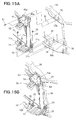
FIGS. 13A and 13B are views showing the procedure of assembling the left top support mechanism of the vehicle body front structure; -
FIGS. 14A and 14B are views showing the procedure of assembling the left bottom support mechanism of the vehicle body front structure; -
FIGS. 15A and 15B are views showing the procedure of assembling the left top support mechanism and the left bottom support mechanism on a front bulkhead; -
FIGS. 16A and 16B are views showing a state in which an impact load has acted on the left top support mechanism and the left bottom support mechanism; -
FIGS. 17A and 17B are views showing an example in which the upper movement bracket of the left top support mechanism is caused to slide toward the rear of the vehicle body; -
FIGS. 18A and 18B are views showing an example in which the lower movement bracket of the left bottom support mechanism is caused to slide toward the rear of the vehicle body; -
FIGS. 19A and 19B are views showing an example in which the cooling system component is moved toward the rear of the vehicle body by the left top support mechanism and the left bottom support mechanism; -
FIGS. 20A and 20B are views showing a state in which thecooling system component 16 has moved toward the rear of the vehicle body; -
FIGS. 21A and 21B are views showing an example of the cooling system component being cooled by the air led in while the vehicle is traveling; and -
FIG. 22 is a view showing an example of the cooling system component vibrating up and down while the vehicle is traveling. - The front side frames, upper members, and upper side frames constituting the framework of a vehicle
body front structure 10 according to the present embodiment are bilaterally symmetric; therefore, the left-side components are described and descriptions of the right-side components are omitted. - As shown in
FIG. 1 , the vehiclebody front structure 10 comprises left and right front side frames 11 provided to the left and right sides of the front of the vehicle body, left and rightupper members 12 provided above the outer sides of the left and right front side frames 11, left and right upper side frames 13 provided to the left and rightupper members 12, abulkhead 15 provided to the left and right upper side frames 13 and the left and right front side frames 11, a coolingsystem support unit 20 which is provided to thebulkhead 15 and which supports acooling system component 16, and awall member 21 provided within the coolingsystem support unit 20. - The
cooling system component 16 comprises a radiator (a rear cooling system component) 17 provided to a region facing anengine compartment 22, and a condenser (a front cooling system component) 18 provided in front of theradiator 17, as shown inFIGS. 2 and3 . - The
radiator 17 is provided to the side facing rearward in the vehicle body, and the radiator cools the cooling water of the engine, for example. Theradiator 17 comprises a coolingfan 17d on the side of a radiatormain body 17c that faces rearward in the vehicle body. - The
condenser 18 is provided in front of theradiator 17 in the vehicle body, and the condenser cools and liquefies refrigerant gas for air conditioning, for example. - An air intake duct (an engine accessory) 23 and a
battery 24 are provided within theengine compartment 22, to the rear of theradiator 17 in the vehicle body. Theair intake duct 23 is a duct for leading air to a carburetor of anengine 25. Asub frame 26 for mounting theengine 25 is provided below theengine compartment 22. - The left
front side frame 11 is disposed on the left side of the vehicle body front, and is made to extend in the vehicle body forward-backward direction, as shown inFIG. 1 . The lefttop member 12 is disposed above and to the outside of the leftfront side frame 11, the rear end being connected to a left front pillar (not shown), and the front end being bonded to afront end 11a of the leftfront side frame 11 by welding (e.g., spot welding). - The left
top side frame 13 extends toward the front of the vehicle body from thesubstantial center 12a of the lefttop member 12, and also extends toward the vehicle-widthwise center in a curving shape up to a lefttop end 15a of thebulkhead 15. - The
bulkhead 15 is a frame member formed into a substantially rectangular shape by left andright side legs 31 provided to the left and right front side frames 11, alower beam 32 provided between bottom ends 31a of the left andright side legs 31, and anupper beam 33 provided between top ends 31b of the left andright side legs 31. - The
lower beam 32 extends between thebottom end 31a of theleft side leg 31 and thebottom end 31a of theright side leg 31. Specifically, aleft end 32a of thelower beam 32 is joined by welding (e.g. spot welding) to thebottom end 31a of theleft side leg 31, and aright end 32a is joined by welding (e.g. spot welding) to thebottom end 31a of theright side leg 31. - The
upper beam 33 extends between thetop end 31b of theleft side leg 31 and thetop end 31b of theright side leg 31. Specifically, the left end (the left top end) 15a of theupper beam 33 is joined by welding (e.g. spot welding) to thetop end 31b of theleft side leg 31, and a right end (a right upper end) 15a is joined by welding (e.g. spot welding) to thetop end 31b of theright side leg 31. The coolingsystem support unit 20 which supports thecooling system component 16 is provided to thebulkhead 15. - The cooling
system support unit 20 comprises left and righttop support mechanisms 35 provided to the left and right ends 15a of theupper beam 33, and left and rightbottom support mechanisms 36 provided to left and right ends 32a of thelower beam 32. - A bumper beam (not shown) is provided to the vehicle body front side of the cooling
system support unit 20. An impact load (a load, input) acts on the bumper beam from the front of the vehicle body toward the rear, whereby the impact load acting on the bumper beam is transferred to the coolingsystem support unit 20 via the bumper beam. - As shown in
FIG. 4 , the lefttop support mechanism 35, is provided to theleft end 15a of theupper beam 33 and is capable of supporting a lefttop part 16a (FIGS. 2 and3 ) of thecooling system component 16, and the lefttop part 16a of thecooling system component 16 is capable of moving toward the rear of the vehicle body. - The left
bottom support mechanism 36 is provided to aleft end part 32a (FIG. 1 ) of thelower beam 32. Within abottom part 16b of thecooling system component 16, a leftbottom part 16c (FIG. 2 ) can be supported by the leftbottom support mechanism 36, and thebottom part 16b of thecooling system component 16 is capable of moving toward the rear of the vehicle body. - As shown in
FIGS. 4 ,5 , and6 , the lefttop support mechanism 35 comprises anupper support bracket 41 provided to theleft end 15a of theupper beam 33, anupper movement bracket 42 provided to the lefttop part 16a (FIGS. 2 and3 ) of thecooling system component 16, and a pair of top fastening means 43 for fastening theupper movement bracket 42 to theupper support bracket 41. - The
upper support bracket 41 has avertical part 45 provided to afront wall 15b in theleft end 15a of theupper beam 33, an inclined part 46 (see alsoFIG. 2 ) jutting at a downward slope toward the front of the vehicle body from the bottom end of thevertical part 45, and ahorizontal part 47 jutting substantially horizontally toward the front of the vehicle body from the front end of theinclined part 46. - The
vertical part 45 has a pair ofattachment holes 45a formed apart from each other by a predetermined gap in the vehicle width direction. By insertingbolts 51 through the pair ofattachment holes 45a of thevertical part 45 and threading the bolts into a pair ofweld nuts 52 of thefront wall 15b, thevertical part 45 is attached along thefront wall 15b by the pair ofbolts 51. In this state, thehorizontal part 47 is positioned below theupper beam 33 and to the front of the upper beam 33 (see alsoFIG. 2 ). On the top surface of thehorizontal part 47, a pair of weld nuts 54 are welded a predetermined gap L1 apart from each other in the vehicle width direction. - The
upper movement bracket 42 is disposed beneath theupper support bracket 41, along thehorizontal part 47 of theupper support bracket 41. Theupper movement bracket 42 has anupper support part 56 which supports a lefttop part 17a (seeFIG. 2 also) of theradiator 17 and a lefttop part 18a (seeFIG. 2 ) of thecondenser 18, and anupper contact part 57 protruding toward the front of the vehicle body from theupper support part 56. - The
upper support part 56 is a substantially trapezoidal region disposed beneath thehorizontal part 47 of theupper support bracket 41 and running along thehorizontal part 47. A topradiator support part 61 is provided to arear end 56a of theupper support part 56, a topcondenser support part 62 is provided toward the front of the vehicle body from the topradiator support part 61, and a pair ofslits 63 are formed in the front left and right ends at a predetermined gap L1 apart from each other in the vehicle width direction. - The top
radiator support part 61 supports the lefttop part 17a by fitting with the lefttop part 17a of theradiator 17. The topcondenser support part 62 supports the lefttop part 18a by fitting with the lefttop part 18a of thecondenser 18. Specifically, theupper support part 56 supports the lefttop part 16a of thecooling system component 16 by being provided to the lefttop part 16a (FIGS. 2 and3 ) of thecooling system component 16. - The pair of
slits 63 are respectively provided inregions 56b of theupper support part 56 that face the upper support bracket 41 (specifically, regions in the front left and right ends that face the pair ofweld nuts 54 of the horizontal part 47). Theseslits 63 are guide grooves formed so as to open toward the front of the vehicle body, both havingopenings 63a in their front ends. - The
upper movement bracket 42 is capable of moving toward the rear of the vehicle body along top fastening bolts 65 (described hereinafter) which fit through theslits 63, and theopenings 63a pass over thetop fastening bolts 65, whereby thetop fastening bolts 65 can be removed from theslits 63. - The
upper contact part 57 is a protruding piece which protrudes substantially horizontally toward the front of the vehicle body from the vehicle-widthwise center in the front end of the upper support part 56 (i.e. the front end center between the pair of slits 63), wherein afront end 57a curves downward. Theupper contact part 57 is made to protrude from afront end center 56c of theupper support part 56, whereby an impact load during a light collision can be made to act on thefront end 57a of theupper contact part 57 from the front of the vehicle body toward the rear of the vehicle body. Theupper movement bracket 42 is fastened to theupper support bracket 41 by the pair of top fastening means 43. - Among the pair of top fastening means 43, one top fastening means 43 is provided toward the outside of the vehicle body from the
upper contact part 57, and the other top fastening means 43 is provided toward the inside of the vehicle body (toward the center of the vehicle body) from theupper contact part 57. - The one top fastening means 43 comprises a top fastening bolt (top fastening member) 65 for fastening the
upper movement bracket 42 to theupper support bracket 41, as well as afirst washer 66, top spring member (top resilient member) 67, andsecond washer 68 which are fitted over thetop fastening bolt 65. Thefirst washer 66 may be used as a bolt referred to as a flange bolt, formed integrally with ahead 65a of thetop fastening bolt 65. - Since the other top fastening means 43 is a structural member identical to the one top fastening means 43, its structural members are denoted by the same symbols as the one top fastening means 43 and descriptions thereof are omitted.
- As shown in
FIGS. 6 and7 , in a state in the one top fastening means 43 in which thetop spring member 67 and thesecond washer 68 are fitted over thetop fastening bolt 65, thetop fastening bolt 65 is passed through one of the slits 63 (the one toward the outer side of the vehicle body) and threaded into one of the weld nuts 54 (the one toward the outer side of the vehicle body). Thetop spring member 67 is a compression spring. - In this state, the
second washer 68 is brought in contact with the bottom surface of the frontleft end 56b of theupper support part 56, and thetop spring member 67 is compressed and fitted in between thefirst washer 66 and thesecond washer 68. - In other words, the
top spring member 67 is fitted in between the frontleft end 56b of theupper support part 56 and thehead 65a of thetop fastening bolt 65 while being compressed via thefirst washer 66 and thesecond washer 68. - In the other top fastening means 43, similar to the one top fastening means 43, the
second washer 68 is brought in contact with the bottom surface of the frontright end 56b of theupper support part 56, and thetop spring member 67 is compressed and fitted in between thefirst washer 66 and thesecond washer 68. - In other words, the
top spring member 67 of the other top fastening means 43 is fitted in between the frontright end 56b of theupper support part 56 and thehead 65a of thetop fastening bolt 65 while being compressed via thefirst washer 66 and thesecond washer 68. - Thus, the one top fastening means 43 is provided toward the outside of the vehicle body from the
upper contact part 57, and the other top fastening means 43 is provided toward the inside of the vehicle body (toward the center of the vehicle body) from theupper contact part 57, whereby the pair of top fastening means 43 are provided to both sides in the vehicle width direction of theupper movement bracket 42. - In this state, the pair of
top fastening bolts 65 are passed respectively through the pair ofslits 63. Theupper movement bracket 42 is fastened to theupper support bracket 41 by the pair of top fastening means 43 so as to be free to move toward the rear of the vehicle body. The lefttop part 16a (FIGS. 2 and3 ) of thecooling system component 16 is thereby provided to the upper beam 33 (thefront wall 15b) via the lefttop support mechanism 35, so as to be free to move toward the rear of the vehicle body. - By providing top fastening means 43 on either of the vehicle-widthwise sides (toward the outside and center of the vehicle body) of the
upper movement bracket 42, the pair of top fastening means 43 can be provided to the substantial center of theupper movement bracket 42 in the forward-backward direction of the vehicle body. Consequently, there is no need to greatly expand the shape of theupper movement bracket 42 toward the rear of the vehicle body, and theupper movement bracket 42 can be reduced in size. - Thus, by reducing the size of the
upper movement bracket 42 and stably sliding theupper movement bracket 42 in the desired direction (toward the rear of the vehicle body), the protruding direction and protruding amount of theupper movement bracket 42 toward the rear of the vehicle body can be suitably controlled. - Furthermore, by fitting the
top spring member 67 between theupper movement bracket 42 and thehead 65a of thetop fastening bolt 65, the fastening load of thetop fastening bolt 65 can be suitably adjusted by thetop spring member 67. It is thereby easy to manage the load when theslit 63 of theupper movement bracket 42 is removed from the top fastening bolt 65 (i.e. the "withdrawal load"), and a satisfactory performance quality can be preserved. - As shown in
FIGS. 5 and8 , the leftbottom support mechanism 36 comprises alower support bracket 71 provided to theleft end part 32a of thelower beam 32, alower movement bracket 72 provided to the leftbottom part 16c (FIG. 2 ) of thecooling system component 16, and a pair of bottom fastening means 73 for fastening thelower movement bracket 72 to thelower support bracket 71. - The
lower support bracket 71 is provided along atop part 32b in theleft end part 32a of thelower beam 32, and is formed into a substantially quadrangular shape. Thelower support bracket 71 hasattachment holes 71a formed in the four corners. By insertingbolts 75 respectively through the attachment holes 71a at the four corners and threading the bolts intoweld nuts 76 of thetop part 32b, thelower support bracket 71 is attached to thetop part 32b by the fourbolts 75. - In this state, a bracket
main body 71b of thelower support bracket 71 is disposed in a state of being raised above thetop part 32b of thelower beam 32, as shown inFIG. 9 . The bracketmain body 71b has aweld nut 78 welded to a vehicle-widthwiseinner side part 71c, and aweld nut 78 welded to a vehicle-widthwiseouter side part 71d. Theweld nut 78 of the vehicle-widthwiseinner side part 71c and theweld nut 78 of the vehicle-widthwiseouter side part 71d are positioned so as to be a predetermined gap L2 apart from each other in the vehicle width direction. - The
lower movement bracket 72 is disposed above thelower support bracket 71 and along thelower support bracket 71. Thelower movement bracket 72 has alower support part 81 for supporting a leftbottom part 17b of theradiator 17 and a left bottom part 18b of thecondenser 18, and alower contact part 82 extending toward the front of the vehicle body from thelower support part 81, as shown inFIG. 2 . - The
lower support part 81 is a substantially rectangular region disposed above thelower support bracket 71 and along thelower support bracket 71. In thelower support part 81, a bottomradiator support part 84 is provided to arear end 81a, a bottomcondenser support part 85 is provided toward the front of the vehicle body from the bottomradiator support part 84, aslit 86 is formed in a vehicle-widthwiseinner side part 81b, and a rearhalf part 87a of aslot 87 is formed in anouter side part 81c. - The bottom
radiator support part 84 supports the leftbottom part 17b by fitting with the leftbottom part 17b of theradiator 17, as shown inFIG. 2 . The bottomcondenser support part 85 supports the left bottom part 18b by fitting with the left bottom part 18b of thecondenser 18. Specifically, thelower movement bracket 72 is a member which supports the leftbottom part 16c of thecooling system component 16 by being provided to the leftbottom part 16c of thecooling system component 16. - The
slit 86 is provided to the vehicle-widthwiseinner side part 81b which is a region facing theweld nut 78 provided to the vehicle-widthwiseinner side part 71c of thelower support bracket 71. Theslit 86 is a guide groove formed so as to open toward the front of the vehicle body, having anopening 86a in the front end. Thelower movement bracket 72 is capable of moving toward the rear of the vehicle body along abottom fastening bolt 91 passed through theslit 86. Thebottom fastening bolt 91 is removed from theslit 86 by passing thebottom fastening bolt 91 out of theopening 86a of theslit 86. - The
slot 87 extends in the forward-backward direction of the vehicle body. The rearhalf part 87a of theslot 87 is a region that faces theweld nut 78 provided to the vehicle-widthwiseouter side part 71d of thelower support bracket 71. - The
lower contact part 82 is a protruding piece extending substantially horizontally toward the front of the vehicle body from the front portion of thelower support part 81, wherein a fronthalf part 87b of theslot 87 is formed in anouter side part 82a, and afront end 82b is bent upward. - The front
half part 87b of theslot 87 extends in a straight line toward the front of the vehicle body from the rearhalf part 87a of theslot 87. Theslot 87 is formed from the fronthalf part 87b and the rearhalf part 87a. Theslot 87 is a long guiding hole extending in a straight line in the vehicle forward-backward direction. Thelower support part 81 is capable of moving toward the rear of the vehicle body along thebottom fastening bolt 91 passed through theslot 87. Theslot 87 and theslit 86 are formed at a predetermined gap L2 from each other in the vehicle width direction. - Due to the
lower contact part 82 protruding from the front of thelower support part 81, the impact load during a light collision is made to act on thefront end 82b of thelower contact part 82 from the rear of the vehicle body toward the front of the vehicle body. Thelower movement bracket 72 is fastened to thelower support bracket 71 by the pair of bottom fastening means 73. - One of the pair of bottom fastening means 73 is provided to the vehicle-widthwise outer side so as to correspond to the slot hole, and the other bottom fastening means 73 is provided to the vehicle-widthwise inner side so as to correspond to the
slit 86. - The one bottom fastening means 73 comprises a bottom fastening bolt (a bottom fastening member) 91 for fastening the
lower movement bracket 72 to thelower support bracket 71, afirst washer 92 through which the bottom fastening bolt is inserted, a bottom spring member (a bottom resilient member) 93, and asecond washer 94. For thebottom fastening bolt 91, a bolt commonly known as a "flange bolt" may be used, in which ahead 91a of thebottom fastening bolt 91 and thefirst washer 92 are integrated. - Since the other bottom fastening means 73 is a structural member identical to the one bottom fastening means 73, the structural members thereof are denoted by the same symbols as the one bottom fastening means 73, and detailed descriptions thereof are omitted.
- As shown in
FIGS. 8 and9 , in a state in the one bottom fastening means 73 in which thefirst washer 92, thebottom spring member 93, and thesecond washer 94 are fitted over thebottom fastening bolt 91, thebottom fastening bolt 91 is passed through theslot 87 and threaded through theweld nut 78. Thebottom spring member 93 is a compression spring. - In this state, the
first washer 92 is brought in contact with thehead 91a of thebottom fastening bolt 91, thesecond washer 94 is brought in contact with theouter side part 81c of thelower support part 81, and thebottom spring member 93 is compressed and fitted in between thefirst washer 92 and thesecond washer 94. In other words, thebottom spring member 93 is fitted in between thehead 91a of thebottom fastening bolt 91 and theouter side part 81c of thelower support part 81 while being compressed via thefirst washer 92 and thesecond washer 94. - In a state in the other bottom fastening means 73 in which the
first washer 92, thebottom spring member 93, and thesecond washer 94 are fitted over thebottom fastening bolt 91, thebottom fastening bolt 91 is passed through theslit 86 and threaded through the other weld nut 78 (the one on the vehicle-widthwise inner side). - In the other bottom fastening means 73, similar to the one bottom fastening means 73, the
second washer 94 is brought in contact with the vehicle-widthwiseinner side part 81b of thelower support part 81, and thebottom spring member 93 is compressed and fitted in between thefirst washer 92 and thesecond washer 94. In other words, thebottom spring member 93 of the other bottom fastening means 73 is fitted in between thehead 91a of thebottom fastening bolt 91 and the vehicle-widthwiseinner side part 81b of thelower support part 81 while being compressed via thefirst washer 92 and thesecond washer 94. - Thus, the one bottom fastening means 73 is provided to the
outer side part 81c of thelower movement bracket 72 and the other bottom fastening means 73 is provided to the vehicle-widthwiseinner side part 81b of thelower movement bracket 72, whereby the pair of bottom fastening means 73 are provided to both vehicle-widthwise sides of thelower movement bracket 72. - In this state, a
bottom fastening bolt 91 is passed through theslit 86 and abottom fastening bolt 91 is passed through theslot 87, whereby thelower movement bracket 72 is fastened to thelower support bracket 71 by the pair of bottom fastening means 73 so as to be free to move toward the rear of the vehicle body. The leftbottom part 16c (FIG. 2 ) of thecooling system component 16 is thereby provided to the lower beam 32 (thetop part 32b) via the leftbottom support mechanism 36 so as to be free to move toward the rear of the vehicle body. - As described above, the
slot 87 extends in the forward-backward direction of the vehicle body. When thelower movement bracket 72 is moved (slid) toward the rear of the vehicle body, theslot 87 can be moved along thebottom fastening bolt 91. - By providing the bottom fastening means 73 to the respective vehicle-widthwise sides of the
lower movement bracket 72, the pair of bottom fastening means 73 can be provided to the substantial center of thelower movement bracket 72 in the vehicle forward-backward direction. Consequently, there is no need to greatly expand the shape of thelower movement bracket 72 toward the rear of the vehicle body, and thelower movement bracket 72 can be reduced in size. - Thus, by reducing the size of the
lower movement bracket 72 and stably sliding thelower movement bracket 72 in the desired direction (toward the rear of the vehicle body), the protruding direction and protruding amount of thelower movement bracket 72 toward the rear of the vehicle body can be suitably controlled. - Furthermore, by fitting the
bottom spring member 93 between thelower movement bracket 72 and thehead 91a of thebottom fastening bolt 91, the fastening load of thebottom fastening bolt 91 can be suitably adjusted by thebottom spring member 93. It is thereby easy to manage the load when theslit 86 of thelower movement bracket 72 is removed from the bottom fastening bolt 91 (i.e. the "withdrawal load"), and a satisfactory performance quality can be preserved. - Furthermore, it is easy to manage the load when the
slot 87 of thelower movement bracket 72 is moved along the bottom fastening bolt 91 (i.e. the "movement load"), and a satisfactory performance quality can be preserved. - According to the vehicle
body front structure 10, the lefttop support mechanism 35 is provided to theupper beam 33, and the lefttop part 16a (FIGS. 2 and3 ) of thecooling system component 16 can be supported by the lefttop support mechanism 35 can be moved toward the rear of the vehicle body, as shown inFIG. 4 . The leftbottom support mechanism 36 is provided to thelower beam 32, and the leftbottom part 16c (FIG. 2 ) of thecooling system component 16 can be supported by the leftbottom support mechanism 36 and moved toward the rear of the vehicle body. Consequently, when an impact load acts on the lefttop support mechanism 35 and the leftbottom support mechanism 36 from the front of the vehicle body, thecooling system component 16 can be moved toward the rear of the vehicle body by thesupport mechanisms cooling system component 16 can be moved toward the rear of the vehicle body to prevent damage to thecooling system component 16 by the impact load. - Furthermore, the
cooling system component 16 can be moved toward the rear of the vehicle body by the lefttop support mechanism 35 of theupper beam 33 and the leftbottom support mechanism 36 of thelower beam 32, whereby there is no need to move the upper beam or the lower beam toward the rear of the vehicle body. Thus, since there is no need to move theupper beam 33 or thelower beam 32 toward the rear of the vehicle body, theupper beam 33 and thelower beam 32 can be provided integrally and firmly to ensure rigidity in thebulkhead 15. It is thereby possible to ensure rigidity in the vehiclebody front structure 10 with thebulkhead 15, and the vehiclebody front structure 10 can be adapted to various power units (e.g. engine transmission units). - The
wall member 21 is disposed within the cooling system support unit 20 (specifically, between thelower support bracket 71 of the leftbottom support mechanism 36 and thelower support bracket 71 of the right bottom support mechanism 36), as shown inFIG. 10 . - The
wall member 21 is disposed in aspace 38 between thelower beam 32 and a centerbottom part 16d in thebottom part 16b of thecooling system component 16, and is provided to thelower beam 32 by a plurality ofbolts 101 and nuts 102 (FIG. 12 ). - In the embodiment, the
bolts 101 andnuts 102 are presented as examples of fastening means for attaching thewall member 21 to thelower beam 32, but grips or the like can also be used as other fastening means. Operability can be further improved by using grips as the fastening means, and cost can be suppressed to keep price low. - The
space 38 is formed between thelower beam 32 and thebottom part 16b of thecooling system component 16 so as to avoid the left and rightbottom support mechanisms 36. - The
bottom part 16b of thecooling system component 16 is comprised of the leftbottom part 16c, a right bottom part, and the centerbottom part 16d. The leftbottom part 16c is a region supported by the leftbottom support mechanism 36, and the right bottom part is a region supported by the rightbottom support mechanism 36. - The
wall member 21 disposed in thespace 38 faces agrill opening 105 disposed forward in the vehicle body from thewall member 21, as shown inFIG. 11 . Thegrill opening 105 is an opening for leading air form the front of the vehicle body into theengine compartment 22 when the vehicle is traveling. - As shown in
FIGS. 10 and12 , thewall member 21 has anattachment seat 111 attached to thelower beam 32, awall panel 112 standing upright from theattachment seat 111 and partitioning thespace 38 to the front and rear, substantially triangular reinforcingribs 113 connecting thewall panel 112 and theattachment seat 111, and aprotruding piece 114 protruding from atop end 112a of thewall panel 112 toward theradiator 17 rearward in the vehicle body. - The
attachment seat 111 is disposed in the vehicle width direction along a centertop part 32c of thelower beam 32, and is attached to the centertop part 32c by thebolts 101 and nuts 102. Theattachment seat 111 is disposed between thelower support bracket 71 of the leftbottom support mechanism 36 and thelower support bracket 71 of the rightbottom support mechanism 36. - The
wall panel 112 is stood upright, rising vertically upward from arear end 111a of theattachment seat 111, and is provided between thecondenser 18 and theradiator 17. Thewall panel 112 stands upright between thecondenser 18 and theradiator 17, whereby thewall member 21 is provided between thecondenser 18 and theradiator 17. Consequently, thespace 38 is partitioned to the front and rear by thewall panel 112. - The
wall panel 112 is disposed in a position separated from thecondenser 18 by a distance L3 toward the rear of the vehicle body. Specifically, thewall member 21 is disposed in a position separated from thecondenser 18 toward the rear of the vehicle body. - Furthermore, the
wall panel 112 is disposed in a position separated from theradiator 17 by a distance L4 toward the front of the vehicle body. Specifically, thewall member 21 is disposed in a position separated from theradiator 17 toward the front of the vehicle body. - Thus, the
wall member 21 is provided between thecondenser 18 and theradiator 17 in the forward-backward direction of the vehicle body, whereby thewall member 21 is disposed in a position separated from thecooling system component 16 in the forward-backward direction of the vehicle body. - The
condenser 18 is supported by the elastically deformable top and bottomcondenser support parts 62, 85 (FIG. 2 ). Theradiator 17 is supported by the elastically deformable top and bottomradiator support parts 61, 84 (FIG. 2 ). Consequently, the cooling system component 16 (thecondenser 18 and the radiator 17) is believed to vibrate up and down due to traveling vibration of the vehicle and interfere with thewall panel 112. - In view of this, the
wall panel 112 is disposed in a position separated from thecondenser 18 and theradiator 17 in the forward-backward direction of the vehicle body (an offset position). Thereby, when the cooling system component 16 (thecondenser 18 and the radiator 17) vibrates up and down due to the traveling vibration of the vehicle, thecondenser 18 and theradiator 17 can be prevented from interfering with the wall panel 112 (the wall member 21). - Furthermore, the cooling system component 16 (the
condenser 18 and the radiator 17) is believed to shake (vibrate) forward and backward and interfere with thewall panel 112 when the vehicle is accelerating or stopping. - In view of this, the
wall panel 112 is disposed separated from thecondenser 18 and theradiator 17 in the forward-backward direction of the vehicle body, whereby thecooling system component 16 shaking (vibrating) forward and backward is prevented from interfering with thewall panel 112. - Particularly, a
bottom part 17e of theradiator 17 of thecooling system component 16 extends below thetop end 112a of thewall panel 112. Consequently, by separating thewall panel 112 from theradiator 17 by a distance L4 toward the front of the vehicle body, thebottom part 17e of theradiator 17 can be prevented from interfering with thewall panel 112. - Additionally, the
wall member 21 is provided between thecondenser 18 and theradiator 17. Consequently, thecondenser 18 is disposed toward the front of the vehicle body from thewall member 21, and theradiator 17 is disposed toward the rear of the vehicle body from thewall member 21. Thereby, only abottom part 18c of thecondenser 18 disposed toward the front of the vehicle body from thewall member 21 is disposed higher than thewall member 21 by a distance H2, and thecondenser 18 andradiator 17 can thereby be moved toward the rear of the vehicle body without interfering with thewall member 21. - Specifically, the
radiator 17 is provided toward the rear of the vehicle body from thewall member 21. Consequently, even if thebottom part 17e of theradiator 17 is extended below thewall member 21, thebottom part 17e of theradiator 17 can be moved rearward in the vehicle body without interfering with thewall member 21. Theradiator 17 can thereby be formed into any desired shape, and the design can have a greater degree of freedom. - Thus, by disposing only the
bottom part 18c of thecondenser 18 above thewall member 21, thecondenser 18 and theradiator 17 can be moved toward the rear of the vehicle body. Thereby, when some obstacle or the like collides lightly with the front of the vehicle body, for example, thecondenser 18 and theradiator 17 are moved toward the rear of the vehicle body and thecondenser 18 and theradiator 17 are prevented from being damaged by the impact load. - Additionally, the
wall panel 112 is disposed in thespace 38 between thelower beam 32 and the centerbottom part 16d of thecooling system component 16, and thespace 38 is partitioned front to rear by thewall panel 112. The wall panel 112 (i.e. the wall member 21) is provided so as to face thegrill opening 105 as shown inFIG. 11 . Consequently, air led in from thegrill opening 105 toward thespace 38 is guided (raised) toward thecooling system component 16 by the wall panel 112 (the wall member 21). Thereby, air led in from thegrill opening 105 can be efficiently led to the cooling system component 16 (thecondenser 18 and the radiator 17), and the cooling performance of thecooling system component 16 can be ensured. - Since the cooling
fan 17d of theradiator 17 rotates while the vehicle is travelling, air led into the vehicle from thegrill opening 105 is led to thecondenser 18 and theradiator 17. It is believed that most of the air passing through thecondenser 18 and theradiator 17 flows to the rear of theengine compartment 22, and some of the air flows so as to return from thebottom part 17e of theradiator 17 to thewall panel 112. - Therefore, when the
wall panel 112 is provided forward in the vehicle body from thecondenser 18, the air returning from thebottom part 17e of theradiator 17 to thewall panel 112 is believed to flow into aspace 39 between thecondenser 18 and theradiator 17. Due to the air returning from thebottom part 17e of theradiator 17 and flowing into thespace 39, it is difficult to ensure the cooling performance of thecondenser 18 and theradiator 17. - When the
wall panel 112 is provided rearward in the vehicle body from theradiator 17, thewall panel 112 becomes too far distanced rearward in the vehicle body from thecondenser 18. Consequently, it becomes difficult for air led in from thegrill opening 105 toward thespace 38 to be led toward thecondenser 18 by thewall panel 112, and it becomes difficult to ensure the cooling performance of thecondenser 18 and theradiator 17. - In view of this, the wall panel 112 (the wall member 21) is provided between the
condenser 18 and theradiator 17. Consequently, air returning to thewall panel 112 from thebottom part 17e of theradiator 17 can be prevented from flowing into thespace 39 between thecondenser 18 and theradiator 17, and air led in from thegrill opening 105 can be led to thecondenser 18 by thewall panel 112. The cooling performance of thecondenser 18 and theradiator 17 can thereby be ensured. - As shown in
FIGS. 10 and12 , a plurality of reinforcingribs 113 are provided at predetermined intervals in the vehicle width direction, and are formed into substantially triangular shapes withbottom sides 113a,vertical sides 113b, and inclinedsides 113c. Thebottom sides 113a extend toward the rear of the vehicle body from thefront end 111b of the front side frames 11 to therear end 111a. Thevertical sides 113b extend upward from therear end 111a of theattachment seat 111 to thetop end 112a of thewall panel 112. Theinclined sides 113c extend at a downward slope from thetop end 112a of thewall panel 112 to thefront end 111b of theattachment seat 111. - By connecting the
wall panel 112 and theattachment seat 111 by the reinforcingribs 113, thewall panel 112 can be reinforced by the reinforcingribs 113, improving the rigidity (strength) of thewall panel 112. Thewall panel 112 can thereby be prevented from being tilted toward the rear of the vehicle body by the air led in from thegrill opening 105 while the vehicle is traveling. - By forming the reinforcing
ribs 113 into substantially triangular shapes, the sides facing thebottom part 18c of thecondenser 18 can be formed into theinclined sides 113c. Consequently, theinclined sides 113c can be distanced far below thebottom part 18c of thecondenser 18, and a large distance H1 can be ensured between theinclined sides 113c and thebottom part 18c of thecondenser 18. Thetop end 112a of the wall panel 112 (specifically, the protruding piece 114) is disposed below thebottom part 18c of thecondenser 18 by a distance H2. - The
top end 112a (the protruding piece 114) of thewall panel 112 is provided between thecondenser 18 and theradiator 17 in the forward-backward direction of the vehicle body. Specifically, thetop end 112a (the protruding piece 114) is disposed in a position (an offset position) distanced from thecooling system component 16 in the forward-backward direction of the vehicle body. Consequently, thecondenser 18 and theradiator 17 do not interfere with thetop end 112a (the protruding piece 114) even when the cooling system component 16 (thecondenser 18 and the radiator 17) vibrated up and down due to traveling vibration of the vehicle. - As described above, forming the reinforcing
ribs 113 into substantially triangular shapes ensures a large distance H1 between theinclined sides 113c and thebottom part 18c of thecondenser 18. Consequently, thecondenser 18 and theradiator 17 can be prevented from interfering with theinclined sides 113c (the wall member 21) when the cooling system component 16 (thecondenser 18 and the radiator 17) vibrates up and down due to traveling vibration of the vehicle. - Thus, when the
cooling system component 16 vibrates up and down, thecooling system component 16 is prevented from interfering with thetop end 112a (the protruding piece 114) and theinclined sides 113c, whereby thecooling system component 16 can be prevented from interfering with thewall member 21. - The protruding
piece 114 protrudes substantially horizontally from thetop end 112a of thewall panel 112 toward theradiator 17 which is rearward in the vehicle body. By providing the protrudingpiece 114 to thetop end 112a of thewall panel 112, the rigidity (strength) of thewall panel 112 can be further improved. - After the air led in from the
grill opening 105 while the vehicle is traveling has passed through thecondenser 18 and theradiator 17, some of the air is believed to flow so as to return from thebottom part 17e of theradiator 17 to thewall panel 112. There is a risk that the air flowing to thewall panel 112 will flow over thetop end 112a of thewall panel 112 and return (recirculate) to the front of thewall panel 112. - In view of this, the protruding
piece 114 is provided to thetop end 112a of thewall panel 112. By providing the protrudingpiece 114 to thetop end 112a, the air returned to thewall panel 112 by the protrudingpiece 114 can be prevented from flowing over thetop end 112a and returning (recirculating) to the front of thewall panel 112. - Next, the method for manufacturing (procedure for assembling) the vehicle
body front structure 10 will be described based onFIGS. 13 through 15 . - As shown in
FIG. 13A , afirst washer 66, atop spring member 67, and asecond washer 68 are fitted over thetop fastening bolt 65 of the one top fastening means 43. In this state, thetop fastening bolt 65 is passed through one of the slits 63 (the one toward the vehicle body outer side) of theupper movement bracket 42, and is threaded through one of the weld nuts 54 (the one toward the vehicle body outer side) of theupper support bracket 41 as shown by arrow A. - Furthermore, the
first washer 66, atop spring member 67, and asecond washer 68 are fitted over thetop fastening bolt 65 of the other top fastening means 43. In this state, thetop fastening bolt 65 is passed through the other slit 63 (the one toward the vehicle body inner side) of theupper movement bracket 42, and is threaded through the other weld nut 54 (the one toward the vehicle body inner side) of theupper support bracket 41 as shown by arrow B. - The
upper movement bracket 42 is fastened to theupper support bracket 41 by the pair of top fastening means 43 so as to be free to move toward the rear of the vehicle body, as shown byFIG. 13B . - As shown in
FIG. 14A , afirst washer 92, abottom spring member 93, and asecond washer 94 are fitted over thebottom fastening bolt 91 of one of the bottom fastening means 73. In this state, thebottom fastening bolt 91 is passed through theslot 87 of thelower movement bracket 72 and threaded through one of the weld nuts 78 (the one toward the vehicle body outer side) of thelower support bracket 71 as shown by arrow C. - Furthermore, a
first washer 92, abottom spring member 93, and asecond washer 94 are fitted over thebottom fastening bolt 91 of the other bottom fastening means 73. In this state, thebottom fastening bolt 91 is passed through theslit 86 of thelower movement bracket 72 and threaded through the other weld nut 78 (the one toward the vehicle body inner side) of thelower support bracket 71 as shown by arrow D. - The
lower movement bracket 72 is fastened to thelower support bracket 71 by the pair of bottom fastening means 73 so as to be free to move toward the rear of the vehicle body, as shown inFIG. 14B . - As shown in
FIG. 15A , with theupper movement bracket 42 having been fastened to theupper support bracket 41, the lefttop part 16a (FIGS. 2 and3 ) of thecooling system component 16 is supported on theupper movement bracket 42. Furthermore, with thelower movement bracket 72 having been fastened to thelower support bracket 71, the leftbottom part 16c (FIG. 2 ) of thecooling system component 16 is supported on thelower movement bracket 72. - With the left
top part 16a of thecooling system component 16 supported on theupper movement bracket 42, thebolts 51 are inserted through the pair ofattachment holes 45a of theupper support bracket 41. The insertedbolts 51 are threaded through therespective weld nuts 52 of the upper beam 33 (thefront wall 15b). - Furthermore, with the left
bottom part 16c (FIG. 2 ) of thecooling system component 16 supported on thelower movement bracket 72, thebolts 75 are inserted through therespective attachment holes 71a in the four corners of thelower support bracket 71. The inserted fourbolts 75 are threaded through theweld nuts 76 of the lower beam 32 (thetop part 32b) as shown by arrow F. - The
upper support bracket 41 is attached to the upper beam 33 (thefront wall 15b) by the pair ofbolts 51, as shown inFIG. 15B . The lefttop part 16a (seeFIGS. 2 and3 ) of thecooling system component 16 are thereby attached to the upper beam 33 (thefront wall 15b) via the lefttop support mechanism 35 so as to be free to move toward the rear of the vehicle body. - Furthermore, the
lower support bracket 71 is attached to the lower beam 32 (thetop part 32b) by the fourbolts 75. The leftbottom part 16c (FIG. 2 ) of thecooling system component 16 is thereby attached to the lower beam 32 (thetop part 32b) via the leftbottom support mechanism 36 so as to be free to move toward the rear of the vehicle body. - Thus, before the
upper support bracket 41 is attached to theupper beam 33, theupper movement bracket 42 is fastened to theupper support bracket 41 by the pair of top fastening means 43. Consequently, it is possible to suitably adjust the fastening load (i.e. the withdrawal load) when theupper movement bracket 42 is fastened to theupper support bracket 41 by the pair of top fastening means 43. - Similarly, before the
lower support bracket 71 is attached to thelower beam 32, thelower movement bracket 72 is fastened to thelower support bracket 71 by the pair of bottom fastening means 73. Consequently, it is possible to suitably adjust the fastening load (i.e. the movement load) when thelower movement bracket 72 is fastened to thelower support bracket 71 by the pair of bottom fastening means 73. - Thus, by suitably adjusting the fastening load of the top and bottom fastening means 43, 73, it is easy to manage the fastening load, and a satisfactory performance quality can be preserved. Therefore, the
cooling system component 16 can be easily attached to the front bulkhead 15 (FIG. 1 ) via the lefttop support mechanism 35 and the leftbottom support mechanism 36. - The following is a description, made based on
FIGS. 16 to 20 , of an example in which the left half of thecooling system component 16 is moved toward the rear of the vehicle body when anobstacle 98 collides lightly (an offset collision) with the left front part of the vehiclebody front structure 10. - As shown in
FIGS. 16A and 16B , when anobstacle 98 has lightly collided with the left front part of the vehiclebody front structure 10, an impact load F1 is transferred to the upper contact part 57 (thefront end 57a) of the lefttop support mechanism 35 as shown by the arrow. At the same time, an impact load F2 is transferred to the lower contact part 82 (thefront end 82b) of the leftbottom support mechanism 36 as shown by the arrow. - The pair of
slits 63 of theupper movement bracket 42 are opened toward the front of the vehicle body as shown inFIGS. 17A and 17B . Thetop spring members 67 are compressed by thetop fastening bolts 65 passed through theslits 63. Theupper movement bracket 42 is fastened to theupper support bracket 41 by the pair of top fastening means 43. The impact load F1 is thereby transferred to thefront end 57a of theupper movement bracket 42, whereby theupper movement bracket 42 moves (slides) toward the rear of the vehicle body as shown by arrow G. - As shown in
FIG. 17B , by causing theupper movement bracket 42 to move toward the rear of the vehicle body, onetop fastening bolt 65 separates from one slit 63 (the one toward the outer side of the vehicle body), and the othertop fastening bolt 65 separates from the other slit 63 (the one toward the inner side of the vehicle body (toward the center of the vehicle body)). - The
slot 87 of thelower movement bracket 72 extends in the forward-backward direction of the vehicle body as shown inFIG. 18A . Theslit 86 of thelower movement bracket 72 is opened toward the front of the vehicle body (FIG. 18B ). Onebottom spring member 93 is compressed by the onebottom fastening bolt 91 that is passed through theslot 87. The otherbottom spring member 93 is compressed by the otherbottom fastening bolt 91 that is passed through theslit 86. - Thus, the
lower movement bracket 72 is fastened to thelower support bracket 71 by the pair of bottom fastening means 73. The impact load F2 is thereby transferred to thefront end 82b of thelower movement bracket 72, whereby thelower movement bracket 72 moves (slides) toward the rear of the vehicle body as shown by arrow H. - When the
lower movement bracket 72 has moved toward the rear of the vehicle body as shown inFIGS. 18B , the otherbottom fastening bolt 91 is separated from theslit 86, and the onebottom fastening bolt 91 remains passed through theslot 87. Specifically, thelower movement bracket 72 is held by the onebottom fastening bolt 91 so as to not separate from thelower support bracket 71. - A shown in
FIGS. 19A and 19B , by moving (sliding) theupper movement bracket 42 toward the rear of the vehicle body as shown by arrow G, the lefttop part 16a (FIGS. 2 and3 ) of thecooling system component 16 is moved toward the rear of the vehicle body as shown by arrow G. By moving (sliding) thelower movement bracket 72 toward the rear of the vehicle body as shown by arrow H, the leftbottom part 16c (FIG. 2 ) of thecooling system component 16 moves toward the rear of the vehicle body as shown by arrow H. The left half of thecooling system component 16 thereby moves toward the rear of the vehicle body. - As shown in
FIGS. 17A and 17B , by moving (sliding) theupper movement bracket 42 toward the rear of the vehicle body as shown by arrow G, the pair oftop fastening bolts 65 can be removed from therespective slits 63. The lefttop part 16a (FIGS. 2 and3 ) of thecooling system component 16 can thereby be removed from theupper movement bracket 41, and the restraint on the lefttop part 16a of thecooling system component 16 can be released. - As shown in
FIGS. 18A and 18B , when thelower movement bracket 72 has moved (slid) toward the rear of the vehicle body as shown by arrow H, thelower movement bracket 72 is held by the onebottom fastening bolt 91 so as to not separate from the lower support bracket 71 (the lower beam 32). - As shown in
FIGS. 20(a) and (b) , thecooling system component 16 moves a comparatively large amount toward the rear of the vehicle body about the lower movement bracket 72 (i.e. the leftbottom part 16c (FIG. 2 ) of the cooling system component 16) as a fulcrum, as shown by arrow G. The lefttop part 16a (FIGS. 2 and3 ) of thecooling system component 16 can thereby be satisfactorily prevented from being damaged by the impact load. - Furthermore, the impact load acting on the
upper beam 33 is eliminated by removing theupper movement bracket 42 from the upper beam 33 (the upper support bracket 41). The deformation of the upper beam 33 (i.e. the front bulkhead 15) by the impact load can thereby be minimized, and maintenance costs (repair costs) can be reduced. - Furthermore, by keeping the
lower movement bracket 72 connected to thelower support bracket 71, the leftbottom part 16c (seeFIG. 2 ) of thecooling system component 16 can be stably moved in the desired direction. When the movement of the leftbottom part 16c of thecooling system component 16 is complete, thecooling system component 16 is kept from separating from thefront bulkhead 15. Thecooling system component 16 can thereby be satisfactorily protected and damage to thecooling system component 16 by the impact load can be more satisfactorily prevented. - The top fastening means 43 are provided to the respective vehicle-widthwise sides of the
upper movement bracket 42 as shown inFIGS. 17A and 17B . Consequently, theupper movement bracket 42 can be stably moved (slid) in the desired direction (rearward in the vehicle body). - Furthermore, the top fastening means 43 are provided on the vehicle-widthwise sides of the
upper movement bracket 42, and the pair of top fastening means 43 are also provided in the substantial center of theupper movement bracket 42 in the forward-backward direction of the vehicle body. Consequently, there is no need for the shape of theupper movement bracket 42 to protrude far toward the rear of the vehicle body, and theupper movement bracket 42 can be reduced in size. - Additionally, as shown in
FIGS. 18A and 18B , since the pair of bottom fastening means 73 are provided to the respective vehicle-widthwise sides of thelower movement bracket 72, thelower movement bracket 72 can be stably moved (slid) in the desired direction (toward the rear of the vehicle body). - Furthermore, the pair of bottom fastening means 73 are provided in the substantial center of the
lower movement bracket 72 in the forward-backward direction of the vehicle body. Consequently, there is no need for the shape of thelower movement bracket 72 to protrude far toward the rear of the vehicle body, and thelower movement bracket 72 can be reduced in size. - As shown in
FIGS. 20A and 20B , by stably sliding theupper movement bracket 42 and thelower movement bracket 72 the desired direction (toward the rear of the vehicle body), thecooling system component 16 can be stably moved toward the rear of the vehicle body. - Furthermore, by reducing the
upper movement bracket 42 and thelower movement bracket 72 in size, the protruding direction and protruding amount of theupper movement bracket 42 and thelower movement bracket 72 toward the rear of the vehicle body can be suitably controlled. Thereby, when thecooling system component 16 has been moved toward the rear of the vehicle body as shown inFIG. 20A , it is possible to satisfactorily avoid interference with thebattery 24 provided behind thecooling system component 16 by theupper movement bracket 42 and thecooling system component 16. - Furthermore, as shown in
FIG. 20B , it is possible to satisfactorily avoid interference with thesub frame 26 provided below theengine compartment 22 by thelower movement bracket 72 and thecooling system component 16. - When the
cooling system component 16 has been moved toward the rear of the vehicle body as shown inFIG. 20A , thecooling system component 16 is believed to interfere with theair intake duct 23 provided behind thecooling system component 16. Thisair intake duct 23 is an elastically deformable member. Consequently, when thecooling system component 16 has interfered with theair intake duct 23, theair intake duct 23 elastically deforms and damage to thecooling system component 16 can be prevented. - Next, an example of the
cooling system component 16 being cooled by the air led in while the vehicle is traveling will be described based onFIGS. 21A and 21B . - Air flows into the vehicle from the
grill opening 105 while the vehicle is traveling as shown by arrows Ia, Ib, and Ic inFIG. 21A . The coolingfan 17d of theradiator 17 rotates. Consequently, the air flowing in from thegrill opening 105 as shown by arrows Ia and Ib is led to thecondenser 18 and theradiator 17 as shown by arrows Ja and Jb. - The wall panel 112 (the wall member 21) is provided to the
space 38 between thelower beam 32 and the centerbottom part 16d of thecooling system component 16. Consequently, the air flowing in from thegrill opening 105 as shown by arrow Ic can be prevented from flowing to thespace 38 by thewall panel 112. The air flowing in from thegrill opening 105 as shown by arrow Ic is led to thecondenser 18 and theradiator 17 by thewall panel 112 as shown by arrow Jc. - The rigidity (strength) of the
wall panel 112 is improved by connecting thewall panel 112 and theattachment seat 111 by the reinforcingribs 113, as shown inFIG. 12 . Consequently, thewall panel 112 can be prevented from tilting rearward in the vehicle body by the air flowing in from thegrill opening 105 as shown by arrow Ic. The air flowing in from thegrill opening 105 as shown by arrow Ic is thereby led reliably to thecondenser 18 and theradiator 17 by thewall panel 112 as shown by arrow Jc. - Thus, all of the air led into the vehicle as shown by arrows Ia, Ib, and Ic is led efficiently through the
condenser 18 and theradiator 17 as shown by arrows Ja, Jb, and Jc. A suitable cooling performance in thecondenser 18 and theradiator 17 can be ensured by all of the air passing through thecondenser 18 and theradiator 17. - Most of the air that has passed through the
condenser 18 and theradiator 17 is led to the rear of theengine compartment 22 as shown by arrows Ka and Kb. The rest of the air is guided to devices (not shown) inside theengine compartment 22 and led downward as shown by arrow Kc. - As shown in
FIG. 21B , the air led downward as shown by arrow Kc flows from thebottom part 17e of theradiator 17 to thewall panel 112 as shown by arrow Lc. - The protruding
piece 114 is provided to thetop end 112a of thewall panel 112. Consequently, the flow of air returning to thewall panel 112 is blocked by the protrudingpiece 114, and the returned air is inhibited from flowing over thetop end 112a of thewall panel 112. The air led downward as shown by arrow Lc is prevented from returning (recirculating) from thebottom part 17e of theradiator 17 to the front of the vehicle body via the protrudingpiece 114 of thewall panel 112. By preventing the air from recirculating to the front of the vehicle body, the air flowing in from thegrill opening 105 as shown by arrows Ia, Ib, and Ic can be more efficiently led to thecondenser 18 and theradiator 17. Therefore, the cooling performance of thecondenser 18 and theradiator 17 can be further improved. - Next, an example of the
cooling system component 16 vibrating up and down while the vehicle is traveling and an example of it vibrating forward and backward will be described based onFIG. 22 . - The wall panel 112 (the wall member 21) is disposed separately between the
condenser 18 and theradiator 17 as shown inFIG. 22 . Thereby, when the cooling system component 16 (thecondenser 18 and the radiator 17) vibrates up and down due to traveling vibration of the vehicle as shown by arrow M, thecondenser 18 and theradiator 17 do not interfere with the wall panel 112 (the wall member 21). - Additionally, by forming the reinforcing
ribs 113 into a substantially triangular shape, theinclined sides 113c, which face toward thebottom part 18c of thecondenser 18, can be distanced far below thebottom part 18c of thecondenser 18. Consequently, a large distance H1 can be ensured between theinclined sides 113c and thebottom part 18c of thecondenser 18. Thereby, when the cooling system component 16 (thecondenser 18 and the radiator 17) vibrates up and down due to traveling vibration of the vehicle, interference with theinclined sides 113c (the wall member 21) by thecondenser 18 and theradiator 17 is avoided. - Furthermore, the
wall panel 112 is disposed as being separated from thecondenser 18 and theradiator 17 in the forward-backward direction of the vehicle body. Even if the cooling system component 16 (thecondenser 18 and the radiator 17) vibrates forward and backward when the vehicle is accelerating or stopping, thecooling system component 16 vibrating forward and backward does not interfere with thewall panel 112. - The vehicle
body front structure 10 and the manufacturing method thereof according to the present invention are not limited to the embodiment previously described, and suitable modifications, improvements, and other changes can be made. - For example, in the previous embodiment, an example was described in which the top and
bottom spring members - Furthermore, in the previous embodiment, an example was described in which an
obstacle 98 lightly collided (an offset collision) with the left front part of the vehiclebody front structure 10, but the present invention is not limited to this example, and the same effects can be achieved in cases in which anobstacle 98 collides lightly (an offset collision) with the right front part of the vehiclebody front structure 10. Additionally, the same effects can be achieved in cases in which anobstacle 98 collides head-on (collides lightly) with the front part of the vehiclebody front structure 10. - Furthermore, in the embodiment, an example was described in which an impact load during a light collision acted on the
upper movement bracket 42 of the lefttop support mechanism 35 and thelower movement bracket 72 of the leftbottom support mechanism 36, but the present invention is not limited to this example and the same effects can be achieved in cases in of a load greater than the impact load during a light collision. - Furthermore, in the embodiment, an example was described in which a pair of top fastening means 43 was provided to the left
top support mechanism 35, but the present invention is not limited to this example and three or more top fastening means 43 may be provided. - Additionally, an example was described in which a pair of bottom fastening means 73 was provided to the left
bottom support mechanism 36, but the present invention is not limited to this example and three or more bottom fastening means 73 can be provided. - Furthermore, the shapes and configurations of the vehicle
body front structure 10, thefront bulkhead 15, thecooling system component 16, the lefttop part 16a, the leftbottom part 16b, thelower beam 32, theupper beam 33, the left and righttop support mechanisms 35, the left and rightbottom support mechanisms 36, theupper support bracket 41, theupper movement bracket 42, the top fastening means 43, theupper contact part 57, theslits top fastening bolts 65, thetop spring members 67, thelower support bracket 71, thelower movement bracket 72, the bottom fastening means 73, thelower contact part 82, theslot 87, thebottom fastening bolts 91, thebottom spring members 93, and other components presented in the embodiment are not limited to the examples given, and suitable modifications can be made. - The present invention is suitable for application in an automobile in which the top part of a cooling system component is provided to an upper beam of a front bulkhead and the bottom part of the cooling system component is provided to a lower beam.
A vehicle body front structure is disclosed in which a cooling system component (16) is provided to an upper beam (33) and a lower beam (32) of a front bulkhead (15). A vehicle body front structure (10) comprises a left top support mechanism (35) provided to the upper beam (33) and a left bottom support mechanism (36) provided to the upper beam (33). The left top support mechanism (35) supports a left top part (16a) of the cooling system component, and supports the left top part of the cooling system component so as to allow the left top part to move toward the rear of the vehicle body. The left bottom support mechanism (36) supports a left bottom part (16b) of the cooling system component, and supports the left bottom part of the cooling system component so as to allow the left bottom part to move toward the rear of the vehicle body.
Claims (13)
- A vehicle body front structure including a front bulkhead (15) having a an upper beam (33) and a lower beam (32), and a cooling system component (16) having a top part (16a) provided to the upper beam (33) and a bottom part (16b) provided to the lower beam (32), said vehicle body front structure comprising:a top support mechanism (35), provided to the upper beam (33), for supporting the top part (16a) of the cooling system component (16) in such a manner as to be movable rearwardly of a vehicle body; anda bottom support mechanism (36), provided to the lower beam (32), for supporting the bottom part (16b) of the cooling system component (16) in such a manner as to be movable rearwardly of the vehicle body.
- The vehicle body front structure of claim 1, wherein the top support mechanism (35) comprises:an upper support bracket (41) provided to the upper beam (33);an upper movement bracket (42) provided to the top part (16a) of the cooling system component (16) and having slits (63; 86) formed in a region (56b) thereof corresponding to the upper support bracket (41) and opening forwardly of the vehicle body; andtop fastening means (43) having top fastening members (65) passed through the slits (63; 85) in order to fasten the upper movement bracket (42) to the upper support bracket (41).
- The vehicle body front structure of claim 2, wherein the top fastening means (43) includes a top resilient member (67) located between the upper movement bracket (42) and the top fastening members (65).
- The vehicle body front structure of claim 2, wherein the upper movement bracket (42) has an upper contact part (57) on which a load acts rearwardly of the vehicle body, and the top fastening means (43) is provided to both vehicle-widthwise sides of the upper movement bracket (42).
- The vehicle body front structure of claim 1, wherein the bottom support mechanism (36) comprises:a lower support bracket (71) provided to the lower beam (32);a lower movement bracket (72) provided to the bottom part (16b) of the cooling system component (16) and having a slot (87) formed in a region (81c) thereof corresponding to the lower support bracket (71) and extending forwardly of the vehicle body; andbottom fastening means (73) having a bottom fastening bolt (91) passed through the slot (87) in order to fasten the lower movement bracket (72) to the lower support bracket (71).
- The vehicle body front structure of claim 5, wherein the bottom fastening means (73) has a bottom resilient member (93) positioned between the lower support bracket (71) and the bottom fastening bolt (91).
- The vehicle body front structure of claim 5, wherein the lower movement bracket (72) has a lower contact part (82) on which a load acts rearwardly of the vehicle body, and the bottom fastening means (73) is provided to both vehicle-widthwise sides of the lower movement bracket (72).
- The vehicle body front structure of claim 1, further comprising a wall member (21) disposed in a space (38) between the lower beam (32) and the bottom part (16b) of the cooling system component (16) and partitioning the space (38) to fore and aft.
- The vehicle body front structure of claim 8, wherein the wall member (21) is disposed in a position distanced from the cooling system component (16) in a forward-backward direction of the vehicle body.
- The vehicle body front structure of claim 8, wherein the wall member (21) comprises:an attachment seat (111) attached to the lower beam (32);a wall panel (112) rising from the attachment seat (111) and partitioning the space (38) to fore and aft; andsubstantially triangular reinforcing ribs (113) connecting the wall panel (112) and the attachment seat (111).
- The vehicle body front structure of claim 10, wherein the wall member (21) has a protruding piece (114) protruding from a top end (112a) of the wall panel (112) toward the cooling system component (16) positioned at a rear part of the vehicle body.
- The vehicle body front structure of claim 1, wherein the cooling system component (16) includes a front cooling system component (18) provided at a front part of the vehicle body, and a rear cooling system component (17) provided on a rear part of the vehicle body, and the wall member (21) is provided between the front cooling system component (18) and the rear cooling system component (17).
- A method for manufacturing a vehicle body front structure in which a top part (16a) of a cooling system component (16) is provided to an upper beam (33) of a front bulkhead (15), and a bottom part (16b) of the cooling system component (16) is provided to a lower beam (32) of the front bulkhead (15), the method comprising the steps of:fastening an upper movement bracket (42), which can be attached to the top part (16a) of the cooling system component (16), to an upper support bracket (41), which can be attached to the upper beam (33), by top fastening means (43) so that the upper movement bracket is free to move toward the rear of the vehicle body;fastening a lower movement bracket (72), which can be attached to the bottom part (16b) of the cooling system component (16), to a lower support bracket (71), which can be attached to the lower beam (32), by bottom fastening means (73) so that the lower movement bracket is free to move toward the rear of the vehicle body;supporting the top part (16a) of the cooling system component (16) on the upper movement bracket (42), and supporting the bottom part (16b) of the cooling system component (16) on the lower movement bracket (72); andattaching the upper support bracket (41) to the upper beam (33), and attaching the lower support bracket (71) to the lower beam (32).
Applications Claiming Priority (2)
| Application Number | Priority Date | Filing Date | Title |
|---|---|---|---|
| JP2010132200A JP5073785B2 (en) | 2010-06-09 | 2010-06-09 | Vehicle body front structure and method for manufacturing vehicle body front structure |
| JP2010147960A JP5073787B2 (en) | 2010-06-29 | 2010-06-29 | Body front structure |
Publications (2)
| Publication Number | Publication Date |
|---|---|
| EP2394885A1 true EP2394885A1 (en) | 2011-12-14 |
| EP2394885B1 EP2394885B1 (en) | 2013-01-30 |
Family
ID=44352097
Family Applications (1)
| Application Number | Title | Priority Date | Filing Date |
|---|---|---|---|
| EP11168909A Not-in-force EP2394885B1 (en) | 2010-06-09 | 2011-06-07 | Vehicle body front structure and manufacturing method thereof |
Country Status (2)
| Country | Link |
|---|---|
| US (1) | US8403404B2 (en) |
| EP (1) | EP2394885B1 (en) |
Cited By (5)
| Publication number | Priority date | Publication date | Assignee | Title |
|---|---|---|---|---|
| DE102011000910A1 (en) * | 2011-02-24 | 2012-08-30 | Dr. Ing. H.C. F. Porsche Aktiengesellschaft | Retaining device for cooling module mounted at front side of motor vehicle e.g. sports car, has slide guide for pivoting cooling module around vertical axis and adjusting to rearward direction against frontal impact |
| WO2014033523A1 (en) * | 2012-08-30 | 2014-03-06 | Toyota Jidosha Kabushiki Kaisha | Vehicle body front structure |
| FR3001696A1 (en) * | 2013-02-06 | 2014-08-08 | Peugeot Citroen Automobiles Sa | Front structure for car, has front facade extending parallel to transverse beam, where front facade is fixed to longitudinal beams via fixing unit intended to slide along longitudinal members in event of impact on front facade |
| FR3037551A1 (en) * | 2015-06-22 | 2016-12-23 | Valeo Systemes Thermiques | FASTENING DEVICE FOR CONNECTING A PORTION OF THE STRUCTURE OF THE FRONT PANEL OF A MOTOR VEHICLE TO THE EXCHANGE HEAD OF A HEAT EXCHANGER DURING A FRONTAL SHOCK ON THE AUTOMOTIVE VEHICLE |
| US20220212724A1 (en) * | 2021-01-06 | 2022-07-07 | Hyundai Motor Company | Radiator support assembly |
Families Citing this family (19)
| Publication number | Priority date | Publication date | Assignee | Title |
|---|---|---|---|---|
| MX2013009589A (en) * | 2011-03-07 | 2014-03-12 | Faurecia Exteriors Gmbh | Multifunctional support for a motor vehicle. |
| FR2981887B1 (en) * | 2011-11-02 | 2015-04-17 | Renault Sas | STRUCTURAL AND MODULAR AIR GUIDE WITH TECHNICAL FRONT FACE FUNCTION OF MOTOR VEHICLE ENGINE AND VEHICLE SO EQUIPPED. |
| JP2013133031A (en) * | 2011-12-27 | 2013-07-08 | Honda Motor Co Ltd | Vehicle-body front structure |
| JP2013166420A (en) * | 2012-02-14 | 2013-08-29 | F Tech:Kk | Vehicle-body front structure member |
| US9623912B2 (en) * | 2012-09-20 | 2017-04-18 | Polaris Industries Inc. | Utility vehicle |
| US9440671B2 (en) | 2012-09-20 | 2016-09-13 | Polaris Industries Inc. | Vehicle |
| US9027683B2 (en) | 2013-09-27 | 2015-05-12 | Toyota Motor Engineering & Manufacturing North America, Inc. | Elastically deformable air inlets and vehicles incorporating the same |
| CN103921847B (en) * | 2014-04-21 | 2016-08-24 | 芜湖恒信汽车内饰制造有限公司 | A kind of manufacture method of easy-maintaining generally applicable automotive front end support |
| KR101764579B1 (en) * | 2014-09-01 | 2017-08-23 | 한온시스템 주식회사 | Radiator and condenser assembly |
| KR102026103B1 (en) * | 2014-09-05 | 2019-09-27 | 한온시스템 주식회사 | Cooling module |
| US10801372B2 (en) * | 2014-10-31 | 2020-10-13 | Modine Manufacturing Company | Cooling module and method for rejecting heat from a coupled engine system and rankine cycle waste heat recovery system |
| FR3048642B1 (en) * | 2016-03-09 | 2018-03-02 | Valeo Systemes Thermiques | COOLING SYSTEM OF A MOTOR VEHICLE AND A SUPPORT FOR FRONT-SIDE MODULE OF SUCH VEHICLE ADAPTED FOR THIS COOLING SYSTEM |
| US9902254B1 (en) * | 2016-07-25 | 2018-02-27 | GM Global Technology Operations LLC | Body mount assembly and a method for mounting a radiator assembly on a vehicle frame before attaching a body structure to the frame |
| US10550754B2 (en) | 2017-05-15 | 2020-02-04 | Polaris Industries Inc. | Engine |
| US10428705B2 (en) | 2017-05-15 | 2019-10-01 | Polaris Industries Inc. | Engine |
| US10639985B2 (en) | 2017-05-15 | 2020-05-05 | Polaris Industries Inc. | Three-wheeled vehicle |
| US10576817B2 (en) * | 2017-05-15 | 2020-03-03 | Polaris Industries Inc. | Three-wheeled vehicle |
| USD904227S1 (en) | 2018-10-26 | 2020-12-08 | Polaris Industries Inc. | Headlight of a three-wheeled vehicle |
| DE102020113206A1 (en) | 2020-05-15 | 2021-11-18 | Bayerische Motoren Werke Aktiengesellschaft | Frame component for front-end module |
Citations (5)
| Publication number | Priority date | Publication date | Assignee | Title |
|---|---|---|---|---|
| US20030062148A1 (en) * | 2001-09-28 | 2003-04-03 | Calsonic Kansei Corporation | Front construction of motor vehicle body & heat exchanger support frame used therefor |
| US20080308333A1 (en) * | 2007-06-18 | 2008-12-18 | Kapadia Ameil A | Front End Module with Breakaway Radiator |
| WO2009072673A1 (en) * | 2007-12-07 | 2009-06-11 | Honda Motor Co., Ltd. | Vehicle front structure |
| JP2009137482A (en) | 2007-12-07 | 2009-06-25 | Honda Motor Co Ltd | Front structure for vehicle |
| EP2080690A1 (en) * | 2006-11-01 | 2009-07-22 | Calsonic Kansei Corporation | Structure for supporting heat exchanger, and vehicle front structure |
Family Cites Families (7)
| Publication number | Priority date | Publication date | Assignee | Title |
|---|---|---|---|---|
| JP3687311B2 (en) | 1997-10-21 | 2005-08-24 | スズキ株式会社 | Auto body front structure |
| JPH11129935A (en) | 1997-10-29 | 1999-05-18 | Aisin Seiki Co Ltd | Front end module for vehicle |
| JPH11263246A (en) | 1998-03-17 | 1999-09-28 | Suzuki Motor Corp | Body front structure for automobile |
| JP2004331002A (en) | 2003-05-12 | 2004-11-25 | Nissan Motor Co Ltd | Front end structure of automobile |
| JP2005035436A (en) * | 2003-07-16 | 2005-02-10 | Calsonic Kansei Corp | Front body structure for automobile |
| US7703566B2 (en) * | 2006-05-19 | 2010-04-27 | Gm Global Technology Operations, Inc. | Integrated automotive tie bar and upper condenser, radiator and fan module brackets |
| JP4852462B2 (en) | 2007-03-30 | 2012-01-11 | 日本プラスト株式会社 | Car cowl structure |
-
2011
- 2011-06-07 EP EP11168909A patent/EP2394885B1/en not_active Not-in-force
- 2011-06-07 US US13/154,664 patent/US8403404B2/en not_active Expired - Fee Related
Patent Citations (5)
| Publication number | Priority date | Publication date | Assignee | Title |
|---|---|---|---|---|
| US20030062148A1 (en) * | 2001-09-28 | 2003-04-03 | Calsonic Kansei Corporation | Front construction of motor vehicle body & heat exchanger support frame used therefor |
| EP2080690A1 (en) * | 2006-11-01 | 2009-07-22 | Calsonic Kansei Corporation | Structure for supporting heat exchanger, and vehicle front structure |
| US20080308333A1 (en) * | 2007-06-18 | 2008-12-18 | Kapadia Ameil A | Front End Module with Breakaway Radiator |
| WO2009072673A1 (en) * | 2007-12-07 | 2009-06-11 | Honda Motor Co., Ltd. | Vehicle front structure |
| JP2009137482A (en) | 2007-12-07 | 2009-06-25 | Honda Motor Co Ltd | Front structure for vehicle |
Cited By (7)
| Publication number | Priority date | Publication date | Assignee | Title |
|---|---|---|---|---|
| DE102011000910A1 (en) * | 2011-02-24 | 2012-08-30 | Dr. Ing. H.C. F. Porsche Aktiengesellschaft | Retaining device for cooling module mounted at front side of motor vehicle e.g. sports car, has slide guide for pivoting cooling module around vertical axis and adjusting to rearward direction against frontal impact |
| WO2014033523A1 (en) * | 2012-08-30 | 2014-03-06 | Toyota Jidosha Kabushiki Kaisha | Vehicle body front structure |
| US9302712B2 (en) | 2012-08-30 | 2016-04-05 | Toyota Jidosha Kabushiki Kaisha | Vehicle body front structure |
| FR3001696A1 (en) * | 2013-02-06 | 2014-08-08 | Peugeot Citroen Automobiles Sa | Front structure for car, has front facade extending parallel to transverse beam, where front facade is fixed to longitudinal beams via fixing unit intended to slide along longitudinal members in event of impact on front facade |
| FR3037551A1 (en) * | 2015-06-22 | 2016-12-23 | Valeo Systemes Thermiques | FASTENING DEVICE FOR CONNECTING A PORTION OF THE STRUCTURE OF THE FRONT PANEL OF A MOTOR VEHICLE TO THE EXCHANGE HEAD OF A HEAT EXCHANGER DURING A FRONTAL SHOCK ON THE AUTOMOTIVE VEHICLE |
| US20220212724A1 (en) * | 2021-01-06 | 2022-07-07 | Hyundai Motor Company | Radiator support assembly |
| US11613311B2 (en) * | 2021-01-06 | 2023-03-28 | Hyundai Motor Company | Radiator support assembly |
Also Published As
| Publication number | Publication date |
|---|---|
| US8403404B2 (en) | 2013-03-26 |
| US20110304176A1 (en) | 2011-12-15 |
| EP2394885B1 (en) | 2013-01-30 |
Similar Documents
| Publication | Publication Date | Title |
|---|---|---|
| EP2394885B1 (en) | Vehicle body front structure and manufacturing method thereof | |
| US11173776B2 (en) | Vehicle body front structure for electric vehicle | |
| JP4853197B2 (en) | Vehicle front structure | |
| CN109131169B (en) | Automobile battery mounting structure | |
| KR100936979B1 (en) | Front end module of a vehicle | |
| EP1690722B1 (en) | Mount apparatus mounting structure | |
| US9446797B2 (en) | Front vehicle-body structure of vehicle | |
| JP7169817B2 (en) | vehicle | |
| JP7177821B2 (en) | Body front structure | |
| JP2018002092A (en) | Bottom surface part structure of cab | |
| JP5767842B2 (en) | Body front structure | |
| JP5073787B2 (en) | Body front structure | |
| CN109664948B (en) | Vehicle front structure | |
| JP6810622B2 (en) | Battery protection structure for driving automobiles | |
| JP5073785B2 (en) | Vehicle body front structure and method for manufacturing vehicle body front structure | |
| CN108001544B (en) | Instrument panel and front cowl attachment | |
| JP2022159722A (en) | front bumper | |
| JP6763828B2 (en) | Body undercover structure | |
| KR102383254B1 (en) | Front vehicle body reinforcing structure | |
| CN107972743B (en) | Supporting member | |
| JP7281106B2 (en) | vehicle front structure | |
| JP7177819B2 (en) | Body front structure | |
| JP2013220789A (en) | Vehicle upper part structure | |
| JP5257349B2 (en) | Mounting structure for in-vehicle equipment | |
| JP2001315666A (en) | Vehicle front structure |
Legal Events
| Date | Code | Title | Description |
|---|---|---|---|
| 17P | Request for examination filed |
Effective date: 20110607 |
|
| AK | Designated contracting states |
Kind code of ref document: A1 Designated state(s): AL AT BE BG CH CY CZ DE DK EE ES FI FR GB GR HR HU IE IS IT LI LT LU LV MC MK MT NL NO PL PT RO RS SE SI SK SM TR |
|
| AX | Request for extension of the european patent |
Extension state: BA ME |
|
| PUAI | Public reference made under article 153(3) epc to a published international application that has entered the european phase |
Free format text: ORIGINAL CODE: 0009012 |
|
| 17Q | First examination report despatched |
Effective date: 20120522 |
|
| GRAP | Despatch of communication of intention to grant a patent |
Free format text: ORIGINAL CODE: EPIDOSNIGR1 |
|
| GRAS | Grant fee paid |
Free format text: ORIGINAL CODE: EPIDOSNIGR3 |
|
| GRAA | (expected) grant |
Free format text: ORIGINAL CODE: 0009210 |
|
| AK | Designated contracting states |
Kind code of ref document: B1 Designated state(s): AL AT BE BG CH CY CZ DE DK EE ES FI FR GB GR HR HU IE IS IT LI LT LU LV MC MK MT NL NO PL PT RO RS SE SI SK SM TR |
|
| REG | Reference to a national code |
Ref country code: GB Ref legal event code: FG4D |
|
| REG | Reference to a national code |
Ref country code: CH Ref legal event code: EP |
|
| REG | Reference to a national code |
Ref country code: AT Ref legal event code: REF Ref document number: 595657 Country of ref document: AT Kind code of ref document: T Effective date: 20130215 Ref country code: CH Ref legal event code: EP |
|
| REG | Reference to a national code |
Ref country code: IE Ref legal event code: FG4D |
|
| REG | Reference to a national code |
Ref country code: DE Ref legal event code: R096 Ref document number: 602011000868 Country of ref document: DE Effective date: 20130328 |
|
| REG | Reference to a national code |
Ref country code: AT Ref legal event code: MK05 Ref document number: 595657 Country of ref document: AT Kind code of ref document: T Effective date: 20130130 |
|
| REG | Reference to a national code |
Ref country code: LT Ref legal event code: MG4D |
|
| REG | Reference to a national code |
Ref country code: NL Ref legal event code: VDEP Effective date: 20130130 |
|
| PG25 | Lapsed in a contracting state [announced via postgrant information from national office to epo] |
Ref country code: LT Free format text: LAPSE BECAUSE OF FAILURE TO SUBMIT A TRANSLATION OF THE DESCRIPTION OR TO PAY THE FEE WITHIN THE PRESCRIBED TIME-LIMIT Effective date: 20130130 Ref country code: AT Free format text: LAPSE BECAUSE OF FAILURE TO SUBMIT A TRANSLATION OF THE DESCRIPTION OR TO PAY THE FEE WITHIN THE PRESCRIBED TIME-LIMIT Effective date: 20130130 Ref country code: NO Free format text: LAPSE BECAUSE OF FAILURE TO SUBMIT A TRANSLATION OF THE DESCRIPTION OR TO PAY THE FEE WITHIN THE PRESCRIBED TIME-LIMIT Effective date: 20130430 Ref country code: IS Free format text: LAPSE BECAUSE OF FAILURE TO SUBMIT A TRANSLATION OF THE DESCRIPTION OR TO PAY THE FEE WITHIN THE PRESCRIBED TIME-LIMIT Effective date: 20130530 Ref country code: SE Free format text: LAPSE BECAUSE OF FAILURE TO SUBMIT A TRANSLATION OF THE DESCRIPTION OR TO PAY THE FEE WITHIN THE PRESCRIBED TIME-LIMIT Effective date: 20130130 Ref country code: ES Free format text: LAPSE BECAUSE OF FAILURE TO SUBMIT A TRANSLATION OF THE DESCRIPTION OR TO PAY THE FEE WITHIN THE PRESCRIBED TIME-LIMIT Effective date: 20130511 Ref country code: BE Free format text: LAPSE BECAUSE OF FAILURE TO SUBMIT A TRANSLATION OF THE DESCRIPTION OR TO PAY THE FEE WITHIN THE PRESCRIBED TIME-LIMIT Effective date: 20130130 Ref country code: BG Free format text: LAPSE BECAUSE OF FAILURE TO SUBMIT A TRANSLATION OF THE DESCRIPTION OR TO PAY THE FEE WITHIN THE PRESCRIBED TIME-LIMIT Effective date: 20130430 |
|
| PG25 | Lapsed in a contracting state [announced via postgrant information from national office to epo] |
Ref country code: SI Free format text: LAPSE BECAUSE OF FAILURE TO SUBMIT A TRANSLATION OF THE DESCRIPTION OR TO PAY THE FEE WITHIN THE PRESCRIBED TIME-LIMIT Effective date: 20130130 Ref country code: FI Free format text: LAPSE BECAUSE OF FAILURE TO SUBMIT A TRANSLATION OF THE DESCRIPTION OR TO PAY THE FEE WITHIN THE PRESCRIBED TIME-LIMIT Effective date: 20130130 Ref country code: LV Free format text: LAPSE BECAUSE OF FAILURE TO SUBMIT A TRANSLATION OF THE DESCRIPTION OR TO PAY THE FEE WITHIN THE PRESCRIBED TIME-LIMIT Effective date: 20130130 Ref country code: NL Free format text: LAPSE BECAUSE OF FAILURE TO SUBMIT A TRANSLATION OF THE DESCRIPTION OR TO PAY THE FEE WITHIN THE PRESCRIBED TIME-LIMIT Effective date: 20130130 Ref country code: PT Free format text: LAPSE BECAUSE OF FAILURE TO SUBMIT A TRANSLATION OF THE DESCRIPTION OR TO PAY THE FEE WITHIN THE PRESCRIBED TIME-LIMIT Effective date: 20130530 Ref country code: PL Free format text: LAPSE BECAUSE OF FAILURE TO SUBMIT A TRANSLATION OF THE DESCRIPTION OR TO PAY THE FEE WITHIN THE PRESCRIBED TIME-LIMIT Effective date: 20130130 Ref country code: GR Free format text: LAPSE BECAUSE OF FAILURE TO SUBMIT A TRANSLATION OF THE DESCRIPTION OR TO PAY THE FEE WITHIN THE PRESCRIBED TIME-LIMIT Effective date: 20130501 |
|
| PG25 | Lapsed in a contracting state [announced via postgrant information from national office to epo] |
Ref country code: HR Free format text: LAPSE BECAUSE OF FAILURE TO SUBMIT A TRANSLATION OF THE DESCRIPTION OR TO PAY THE FEE WITHIN THE PRESCRIBED TIME-LIMIT Effective date: 20130130 Ref country code: RS Free format text: LAPSE BECAUSE OF FAILURE TO SUBMIT A TRANSLATION OF THE DESCRIPTION OR TO PAY THE FEE WITHIN THE PRESCRIBED TIME-LIMIT Effective date: 20130130 |
|
| PG25 | Lapsed in a contracting state [announced via postgrant information from national office to epo] |
Ref country code: RO Free format text: LAPSE BECAUSE OF FAILURE TO SUBMIT A TRANSLATION OF THE DESCRIPTION OR TO PAY THE FEE WITHIN THE PRESCRIBED TIME-LIMIT Effective date: 20130130 Ref country code: EE Free format text: LAPSE BECAUSE OF FAILURE TO SUBMIT A TRANSLATION OF THE DESCRIPTION OR TO PAY THE FEE WITHIN THE PRESCRIBED TIME-LIMIT Effective date: 20130130 Ref country code: CZ Free format text: LAPSE BECAUSE OF FAILURE TO SUBMIT A TRANSLATION OF THE DESCRIPTION OR TO PAY THE FEE WITHIN THE PRESCRIBED TIME-LIMIT Effective date: 20130130 Ref country code: SK Free format text: LAPSE BECAUSE OF FAILURE TO SUBMIT A TRANSLATION OF THE DESCRIPTION OR TO PAY THE FEE WITHIN THE PRESCRIBED TIME-LIMIT Effective date: 20130130 Ref country code: DK Free format text: LAPSE BECAUSE OF FAILURE TO SUBMIT A TRANSLATION OF THE DESCRIPTION OR TO PAY THE FEE WITHIN THE PRESCRIBED TIME-LIMIT Effective date: 20130130 |
|
| PG25 | Lapsed in a contracting state [announced via postgrant information from national office to epo] |
Ref country code: CY Free format text: LAPSE BECAUSE OF FAILURE TO SUBMIT A TRANSLATION OF THE DESCRIPTION OR TO PAY THE FEE WITHIN THE PRESCRIBED TIME-LIMIT Effective date: 20130130 |
|
| PLBE | No opposition filed within time limit |
Free format text: ORIGINAL CODE: 0009261 |
|
| STAA | Information on the status of an ep patent application or granted ep patent |
Free format text: STATUS: NO OPPOSITION FILED WITHIN TIME LIMIT |
|
| PG25 | Lapsed in a contracting state [announced via postgrant information from national office to epo] |
Ref country code: IT Free format text: LAPSE BECAUSE OF FAILURE TO SUBMIT A TRANSLATION OF THE DESCRIPTION OR TO PAY THE FEE WITHIN THE PRESCRIBED TIME-LIMIT Effective date: 20130130 |
|
| 26N | No opposition filed |
Effective date: 20131031 |
|
| PG25 | Lapsed in a contracting state [announced via postgrant information from national office to epo] |
Ref country code: MC Free format text: LAPSE BECAUSE OF FAILURE TO SUBMIT A TRANSLATION OF THE DESCRIPTION OR TO PAY THE FEE WITHIN THE PRESCRIBED TIME-LIMIT Effective date: 20130130 |
|
| REG | Reference to a national code |
Ref country code: DE Ref legal event code: R097 Ref document number: 602011000868 Country of ref document: DE Effective date: 20131031 |
|
| REG | Reference to a national code |
Ref country code: IE Ref legal event code: MM4A |
|
| PG25 | Lapsed in a contracting state [announced via postgrant information from national office to epo] |
Ref country code: IE Free format text: LAPSE BECAUSE OF NON-PAYMENT OF DUE FEES Effective date: 20130607 |
|
| PGFP | Annual fee paid to national office [announced via postgrant information from national office to epo] |
Ref country code: FR Payment date: 20140609 Year of fee payment: 4 |
|
| REG | Reference to a national code |
Ref country code: CH Ref legal event code: PL |
|
| REG | Reference to a national code |
Ref country code: DE Ref legal event code: R084 Ref document number: 602011000868 Country of ref document: DE |
|
| PG25 | Lapsed in a contracting state [announced via postgrant information from national office to epo] |
Ref country code: MT Free format text: LAPSE BECAUSE OF FAILURE TO SUBMIT A TRANSLATION OF THE DESCRIPTION OR TO PAY THE FEE WITHIN THE PRESCRIBED TIME-LIMIT Effective date: 20130130 |
|
| REG | Reference to a national code |
Ref country code: DE Ref legal event code: R084 Ref document number: 602011000868 Country of ref document: DE Effective date: 20150210 |
|
| PG25 | Lapsed in a contracting state [announced via postgrant information from national office to epo] |
Ref country code: LI Free format text: LAPSE BECAUSE OF NON-PAYMENT OF DUE FEES Effective date: 20140630 Ref country code: CH Free format text: LAPSE BECAUSE OF NON-PAYMENT OF DUE FEES Effective date: 20140630 |
|
| PG25 | Lapsed in a contracting state [announced via postgrant information from national office to epo] |
Ref country code: SM Free format text: LAPSE BECAUSE OF FAILURE TO SUBMIT A TRANSLATION OF THE DESCRIPTION OR TO PAY THE FEE WITHIN THE PRESCRIBED TIME-LIMIT Effective date: 20130130 |
|
| PG25 | Lapsed in a contracting state [announced via postgrant information from national office to epo] |
Ref country code: TR Free format text: LAPSE BECAUSE OF FAILURE TO SUBMIT A TRANSLATION OF THE DESCRIPTION OR TO PAY THE FEE WITHIN THE PRESCRIBED TIME-LIMIT Effective date: 20130130 |
|
| PG25 | Lapsed in a contracting state [announced via postgrant information from national office to epo] |
Ref country code: MK Free format text: LAPSE BECAUSE OF FAILURE TO SUBMIT A TRANSLATION OF THE DESCRIPTION OR TO PAY THE FEE WITHIN THE PRESCRIBED TIME-LIMIT Effective date: 20130130 Ref country code: LU Free format text: LAPSE BECAUSE OF NON-PAYMENT OF DUE FEES Effective date: 20130607 Ref country code: HU Free format text: LAPSE BECAUSE OF FAILURE TO SUBMIT A TRANSLATION OF THE DESCRIPTION OR TO PAY THE FEE WITHIN THE PRESCRIBED TIME-LIMIT; INVALID AB INITIO Effective date: 20110607 |
|
| GBPC | Gb: european patent ceased through non-payment of renewal fee |
Effective date: 20150607 |
|
| REG | Reference to a national code |
Ref country code: FR Ref legal event code: ST Effective date: 20160229 |
|
| PG25 | Lapsed in a contracting state [announced via postgrant information from national office to epo] |
Ref country code: GB Free format text: LAPSE BECAUSE OF NON-PAYMENT OF DUE FEES Effective date: 20150607 |
|
| PG25 | Lapsed in a contracting state [announced via postgrant information from national office to epo] |
Ref country code: FR Free format text: LAPSE BECAUSE OF NON-PAYMENT OF DUE FEES Effective date: 20150630 |
|
| PG25 | Lapsed in a contracting state [announced via postgrant information from national office to epo] |
Ref country code: AL Free format text: LAPSE BECAUSE OF FAILURE TO SUBMIT A TRANSLATION OF THE DESCRIPTION OR TO PAY THE FEE WITHIN THE PRESCRIBED TIME-LIMIT Effective date: 20130130 |
|
| PGFP | Annual fee paid to national office [announced via postgrant information from national office to epo] |
Ref country code: DE Payment date: 20210511 Year of fee payment: 11 |
|
| REG | Reference to a national code |
Ref country code: DE Ref legal event code: R119 Ref document number: 602011000868 Country of ref document: DE |
|
| PG25 | Lapsed in a contracting state [announced via postgrant information from national office to epo] |
Ref country code: DE Free format text: LAPSE BECAUSE OF NON-PAYMENT OF DUE FEES Effective date: 20230103 |