JP5073785B2 - Vehicle body front structure and method for manufacturing vehicle body front structure - Google Patents
Vehicle body front structure and method for manufacturing vehicle body front structure Download PDFInfo
- Publication number
- JP5073785B2 JP5073785B2 JP2010132200A JP2010132200A JP5073785B2 JP 5073785 B2 JP5073785 B2 JP 5073785B2 JP 2010132200 A JP2010132200 A JP 2010132200A JP 2010132200 A JP2010132200 A JP 2010132200A JP 5073785 B2 JP5073785 B2 JP 5073785B2
- Authority
- JP
- Japan
- Prior art keywords
- vehicle body
- bracket
- moving bracket
- cooling system
- support
- Prior art date
- Legal status (The legal status is an assumption and is not a legal conclusion. Google has not performed a legal analysis and makes no representation as to the accuracy of the status listed.)
- Expired - Fee Related
Links
Images

Landscapes
- Body Structure For Vehicles (AREA)
Description
本発明は、フロントバルクヘッドのアッパ梁部およびロア梁部に冷却系部品が設けられた車体前部構造および車体前部構造の製造方法に関する。 The present invention relates to a vehicle body front structure in which cooling system components are provided in an upper beam portion and a lower beam portion of a front bulkhead, and a method for manufacturing the vehicle body front structure.
車体前部構造のなかには、左右のフロントサイドフレームおよび左右のアッパメンバーにフロントバルクヘッドが設けられ、フロントバルクヘッドに冷却系部品が設けられたものがある。
この冷却系部品は、フロントバルクヘッドのアッパ梁部に冷却系部品の上部が取り付けられ、フロントバルクヘッドのロア梁部にロア支持ブラケットを介して冷却系部品の下部が取り付けられている。
そして、アッパ梁部が左右のアッパメンバーに車体後方に向けて移動可能にボルトで締結され、ロア支持ブラケットがロア梁部に車体後方に向けて移動可能にボルトで締結されている。
Some vehicle body front structures have front bulkheads on left and right front side frames and left and right upper members, and cooling components on the front bulkhead.
In this cooling system part, the upper part of the cooling system part is attached to the upper beam part of the front bulkhead, and the lower part of the cooling system part is attached to the lower beam part of the front bulkhead via the lower support bracket.
The upper beam part is fastened to the left and right upper members with bolts so as to be movable toward the rear of the vehicle body, and the lower support bracket is fastened to the lower beam part with bolts so as to be movable toward the rear of the vehicle body.
この車体前部構造によれば、例えば、軽衝突によって車体前部に衝撃荷重(入力)が作用した場合に、アッパ梁部とともに冷却系部品の上部を車体後方に向けて移動させることが可能である。同時に、ロア支持ブラケットとともに冷却系部品の下部を車体後方に向けて移動させることが可能である。
冷却系部品の上部および下部を車体後方に向けて移動させることで、衝撃荷重で冷却系部品が損傷することを防ぐことができる(例えば、特許文献1参照。)。
According to this vehicle body front structure, for example, when an impact load (input) is applied to the vehicle body front part due to a light collision, it is possible to move the upper part of the cooling system part together with the upper beam part toward the rear of the vehicle body. is there. At the same time, the lower part of the cooling system part can be moved together with the lower support bracket toward the rear of the vehicle body.
By moving the upper part and the lower part of the cooling system part toward the rear of the vehicle body, it is possible to prevent the cooling system part from being damaged by an impact load (see, for example, Patent Document 1).
ここで、通常の車体前部構造は、アッパ梁部およびロア梁部を左右のサイド脚部で一体に連結することによりフロントバルクヘッドを一体的な略矩形枠体とし、フロントバルクヘッドの剛性を確保している。
しかし、特許文献1の車体前部構造は、アッパ梁部が左右のアッパメンバーに車体後方に向けて移動可能に取り付けられている。
このため、フロントバルクヘッドの剛性を確保する工夫が必要であり、この観点から改良の余地が残されていた。
Here, the normal front body structure of the vehicle body has a front bulkhead integrated into a substantially rectangular frame by integrally connecting the upper beam portion and the lower beam portion with the left and right side leg portions, and the rigidity of the front bulkhead is increased. Secured.
However, in the vehicle body front structure of Patent Document 1, the upper beam portion is attached to the left and right upper members so as to be movable toward the rear of the vehicle body.
For this reason, a device for securing the rigidity of the front bulkhead is required, and there is room for improvement from this viewpoint.
また、特許文献1の車体前部構造は、アッパ梁部が左右のアッパメンバーに車体後方に向けて移動可能にボルトで締結され、ロア支持ブラケットがロア梁部に車体後方に向けて移動可能にボルトで締結されている。
よって、アッパ梁部を左右のアッパメンバー(すなわち、車体)に組み付ける際に、アッパ梁部が車体後方に向けて移動可能となるようにボルトの締結荷重を調整する必要がある。
同様に、ロア支持ブラケットをロア梁部(すなわち、車体)に組み付ける際に、ロア支持ブラケットが車体後方に向けて移動可能となるようにボルトの締結荷重を調整する必要がある。
Further, in the vehicle body front structure of Patent Document 1, the upper beam part is fastened to the left and right upper members with bolts so as to be movable toward the rear of the vehicle body, and the lower support bracket is movable toward the lower beam part toward the rear of the vehicle body. It is fastened with bolts.
Therefore, when the upper beam portion is assembled to the left and right upper members (that is, the vehicle body), it is necessary to adjust the fastening load of the bolt so that the upper beam portion can move toward the rear of the vehicle body.
Similarly, when the lower support bracket is assembled to the lower beam portion (that is, the vehicle body), it is necessary to adjust the fastening load of the bolts so that the lower support bracket can move toward the rear of the vehicle body.
よって、アッパ梁部やロア支持ブラケットを部品単位で組み付ける際にボルトの締結荷重を調整する場合に比べて締結荷重の調整に手間がかかることが考えられる。
このため、フロントバルクヘッドに冷却系部品を組み付ける作業に手間がかかり、この観点から改良の余地が残されていた。
Therefore, it can be considered that it takes time to adjust the fastening load as compared with the case where the fastening load of the bolt is adjusted when the upper beam portion and the lower support bracket are assembled in units of parts.
For this reason, the work of assembling the cooling system parts to the front bulkhead takes time, and there remains room for improvement from this point of view.
本発明は、衝撃荷重による冷却系部品の損傷を防ぐことができ、さらに、バルクヘッドの剛性を確保でき、加えて、フロントバルクヘッドに冷却系部品を容易に組み付けることができる車体前部構造および車体前部構造の製造方法を提供することを課題とする。 The present invention can prevent damage to cooling system parts due to impact load, can further secure the rigidity of the bulkhead, and in addition, a vehicle body front structure capable of easily assembling the cooling system parts to the front bulkhead and It is an object of the present invention to provide a method for manufacturing a vehicle body front part structure.
請求項1に係る発明は、フロントバルクヘッドのアッパ梁部に冷却系部品の上部が設けられるとともに、前記フロントバルクヘッドのロア梁部に冷却系部品の下部が設けられた車体前部構造において、前記アッパ梁部に設けられるとともに前記冷却系部品の上部を支持可能で、かつ、前記冷却系部品の上部を車体後方に向けて移動可能な上支持機構と、前記ロア梁部に設けられるとともに前記冷却系部品の下部を支持可能で、かつ、前記冷却系部品の下部を車体後方に向けて移動可能な下支持機構と、を備え、前記上支持機構は、前記アッパ梁部に設けられたアッパ支持ブラケットと、前記アッパ支持ブラケットに対向する部位に車体前方へ向けて開口するスリットが形成されるとともに、前記冷却系部品の上部に設けられたアッパ移動ブラケットと、前記アッパ移動ブラケットを前記アッパ支持ブラケットに締結するために前記スリットに貫通された上締結部材を有する上締結手段と、を備え、前記上締結手段は、前記アッパ移動ブラケットおよび前記上締結部材間に介在させた上弾性部材を有し、前記下支持機構は、前記ロア梁部に設けられたロア支持ブラケットと、前記ロア支持ブラケットに対向する部位に車体前後方向へ向けて延びるスロット穴が形成されるとともに、前記冷却系部品の下部に設けられたロア移動ブラケットと、前記ロア移動ブラケットを前記ロア支持ブラケットに締結するために前記スロット穴に貫通された下締結部材を有する下締結手段と、を備え、前記下締結手段は、前記ロア移動ブラケットおよび前記下締結部材間に介在させた下弾性部材を有し、前記アッパ支持ブラケットに前記アッパ移動ブラケットが前記上締結手段で締結された状態で、前記アッパ移動ブラケットおよび前記アッパ支持ブラケットを、それぞれ前記冷却系部品の上部および前記アッパ梁部に取付可能とし、前記ロア支持ブラケットに前記ロア移動ブラケットが前記下締結手段で締結された状態で、前記ロア移動ブラケットおよび前記ロア支持ブラケットを、それぞれ前記冷却系部品の下部および前記ロア梁部に取付可能とし、前記アッパ移動ブラケットに前記スリットが形成され、かつ、前記ロア移動ブラケットに前記スロット穴が形成されることにより、前記アッパ移動ブラケット、前記ロア移動ブラケットに衝撃荷重が作用した際に、前記スリットを前記上締結部材から外した状態で、前記スロット穴を前記下締結部材に沿って移動可能としたことを特徴とする。 The invention according to claim 1 is a vehicle body front structure in which an upper beam part of the front bulkhead is provided with an upper part of a cooling system part and a lower part of the cooling system part is provided in a lower beam part of the front bulkhead. An upper support mechanism provided on the upper beam part and capable of supporting the upper part of the cooling system part and capable of moving the upper part of the cooling system part toward the rear of the vehicle body, and provided on the lower beam part and the A lower support mechanism capable of supporting the lower part of the cooling system part and moving the lower part of the cooling system part toward the rear of the vehicle body , wherein the upper support mechanism is provided in the upper beam portion. A support bracket and a slit that opens toward the front of the vehicle body are formed at a portion facing the upper support bracket, and an upper moving bra provided at an upper portion of the cooling system component. And an upper fastening means having an upper fastening member penetrated by the slit for fastening the upper moving bracket to the upper support bracket, and the upper fastening means includes the upper moving bracket and the upper moving bracket. An upper elastic member interposed between the fastening members, and the lower support mechanism includes a lower support bracket provided on the lower beam portion, and a slot extending in a longitudinal direction of the vehicle body at a portion facing the lower support bracket. A lower fastening having a lower moving bracket provided at a lower portion of the cooling system component and a lower fastening member penetrating through the slot hole for fastening the lower moving bracket to the lower support bracket. And the lower fastening means has a lower elastic member interposed between the lower moving bracket and the lower fastening member. With the upper moving bracket being fastened to the upper support bracket by the upper fastening means, the upper moving bracket and the upper support bracket can be attached to the upper part of the cooling system component and the upper beam part, respectively, With the lower moving bracket being fastened to the lower support bracket by the lower fastening means, the lower moving bracket and the lower support bracket can be attached to the lower part of the cooling system component and the lower beam part, respectively. The slit is formed in the moving bracket, and the slot hole is formed in the lower moving bracket, so that when the impact load is applied to the upper moving bracket and the lower moving bracket, the slit is fastened. With the slot hole removed from the member, It is possible to move along the fastening member .
請求項2は、前記アッパ移動ブラケットに、車体後方に向けて荷重が作用するアッパ当接部を有し、前記アッパ移動ブラケットの車幅方向両側に前記上締結手段が設けられたことを特徴とする。 According to a second aspect of the present invention, the upper moving bracket has an upper abutting portion on which a load acts toward the rear of the vehicle body, and the upper fastening means is provided on both sides in the vehicle width direction of the upper moving bracket. To do.
請求項3は、前記ロア移動ブラケットに、車体後方に向けて荷重が作用するロア当接部を有し、前記ロア移動ブラケットの車幅方向両側に前記下締結手段が設けられたことを特徴とする。 According to a third aspect of the present invention, the lower moving bracket has a lower abutting portion on which a load acts toward the rear of the vehicle body, and the lower fastening means is provided on both sides in the vehicle width direction of the lower moving bracket. To do.
請求項1に係る発明では、アッパ梁部に上支持機構を設け、この上支持機構で冷却系部品の上部を支持可能で、かつ、車体後方に向けて移動可能とした。
また、ロア梁部に下支持機構を設け、この下支持機構で冷却系部品の下部を支持可能で、かつ、車体後方に向けて移動可能とした。
In the invention according to claim 1, an upper support mechanism is provided in the upper beam portion, and the upper support mechanism can support the upper part of the cooling system component and can move toward the rear of the vehicle body.
In addition, a lower support mechanism is provided in the lower beam portion, and the lower support mechanism can support the lower part of the cooling system component and can move toward the rear of the vehicle body.
よって、上下の支持機構に荷重(入力)が車体前方から車体後方に向けて作用した際に、上下の支持機構で冷却系部品を車体後方に向けて移動させることができる。
これにより、冷却系部品を車体後方に向けて移動させて、冷却系部品が荷重で損傷することを防ぐことができる。
Therefore, when a load (input) acts on the upper and lower support mechanisms from the front of the vehicle body toward the rear of the vehicle body, the cooling system components can be moved toward the rear of the vehicle body by the upper and lower support mechanisms.
Thereby, it is possible to prevent the cooling system component from being damaged by the load by moving the cooling system component toward the rear of the vehicle body.
さらに、アッパ梁部およびロア部材に上下の支持機構を設け、上下の支持機構で冷却系部品を車体後方に向けて移動可能とした。
よって、アッパ梁部やロア梁部を車体後方に移動させる必要がないので、アッパ梁部やロア梁部を一体的に強固に設ける(取り付ける)ことができ、フロントバルクヘッドの剛性を確保できる。
これにより、フロントバルクヘッドで車体前部構造の剛性を確保することが可能になり、車体前部構造の剛性を多種のパワーユニット(例えば、エンジン・トランスミッションユニット)に対応させることができる。
Furthermore, upper and lower support mechanisms are provided on the upper beam portion and the lower member, and the cooling system parts can be moved toward the rear of the vehicle body by the upper and lower support mechanisms.
Therefore, since it is not necessary to move the upper beam portion and the lower beam portion to the rear of the vehicle body, the upper beam portion and the lower beam portion can be provided (attached) firmly and integrally, and the rigidity of the front bulkhead can be ensured.
Thus, the front bulkhead can ensure the rigidity of the vehicle body front structure, and the rigidity of the vehicle body front structure can be made compatible with various power units (for example, engine / transmission unit).
また、請求項1に係る発明では、アッパ移動ブラケットのスリットを車体前方へ向けて開口した。そして、スリットを貫通した上締結部材でアッパ移動ブラケットをアッパ支持ブラケットに締結した。
よって、アッパ移動ブラケットを車体後方に移動(スライド移動)させることによりスリットを上締結部材から外すことができる。
Moreover, in the invention which concerns on Claim 1 , the slit of the upper movement bracket was opened toward the vehicle body front. Then, the upper moving bracket was fastened to the upper support bracket with the upper fastening member penetrating the slit.
Therefore, the slit can be removed from the upper fastening member by moving the upper moving bracket rearward (sliding).
すなわち、アッパ移動ブラケットをアッパ支持ブラケット(アッパ梁部)から外すことができる。
これにより、冷却系部品の上部の拘束を解除できるので、冷却系部品の上部を車体後方に比較的大きく移動させることができ、冷却系部品が荷重で損傷することを一層良好に防ぐことができる。
That is, the upper moving bracket can be detached from the upper support bracket (upper beam portion).
As a result, the restraint on the upper part of the cooling system part can be released, so that the upper part of the cooling system part can be moved relatively far rearward of the vehicle body, and the cooling system part can be further prevented from being damaged by a load. .
さらに、アッパ移動ブラケットをアッパ梁部(アッパ支持ブラケット)から外すことで、アッパ梁部に荷重が作用することを除去できる。
これにより、アッパ梁部(すなわち、フロントバルクヘッド)が荷重で変形することを抑えることができ、修理費(リペア費)を低減することができる。
Further, by removing the upper moving bracket from the upper beam portion (upper support bracket), it is possible to remove the load acting on the upper beam portion.
Thereby, it can suppress that an upper beam part (namely, front bulkhead) deform | transforms with a load, and it can reduce repair cost (repair cost).
また、請求項1に係る発明では、アッパ移動ブラケットおよび上締結部材間に上弾性部材を介在させることで、上締結部材の締結荷重を上弾性部材で好適に調整することができる。
これにより、アッパ移動ブラケットのスリットを上締結部材から外す際の荷重(すなわち、「抜去荷重」)の管理が容易になり、性能品質を良好に保つことができる。
さらに、請求項1に係る発明では、ロア移動ブラケットのスロット穴を車体前後方向へ向けて延ばした。そして、スロット穴を貫通した下締結部材でロア移動ブラケットをロア支持ブラケットに締結した。
よって、ロア移動ブラケットを車体後方に移動(スライド移動)させる際に、スロット穴を下締結部材に沿わせて移動することができる。
これにより、ロア移動ブラケット(すなわち、冷却系部品)を所望方向に安定的にスライド移動させることができる。
そして、ロア移動ブラケット(冷却系部品)のスライド移動が完了した際に、冷却系部品をフロントバルクヘッドから離れないように保つことができる。
これにより、冷却系部品を良好に保護して冷却系部品が荷重で損傷することを一層良好に防ぐことができる。
また、請求項1に係る発明では、ロア移動ブラケットおよび下締結部材間に下弾性部材を介在させることで、下締結部材の締結荷重を下弾性部材で好適に調整することができる。
これにより、ロア移動ブラケットのスロット穴を下締結部材に沿わせて移動する際の荷重(すなわち、「移動荷重」)の管理が容易になり、性能品質を良好に保つことができる。
さらに、請求項1に係る発明では、フロントバルクヘッドのアッパ梁部にアッパ支持ブラケットを取り付ける前に、アッパ支持ブラケットにアッパ移動ブラケットを上締結手段で締結するようにした。
よって、アッパ支持ブラケットにアッパ移動ブラケットを上締結手段で締結する際の締結荷重を好適に調整することができる。
同様に、フロントバルクヘッドのロア梁部にロア支持ブラケットを取り付ける前に、ロア支持ブラケットにロア移動ブラケットを下締結手段で締結するようにした。
よって、ロア支持ブラケットにロア移動ブラケットを下締結手段で締結する際の締結荷重を好適に調整することができる。
このように、上下の締結手段の締結荷重を好適に調整することで、締結荷重の管理が容易になり、性能品質を良好に保つことができる。
したがって、フロントバルクヘッドに冷却系部品を容易に組み付けることができる。
In the invention according to claim 1 , the upper elastic member is interposed between the upper moving bracket and the upper fastening member, so that the fastening load of the upper fastening member can be suitably adjusted by the upper elastic member.
Thereby, management of the load (that is, “extraction load”) when removing the slit of the upper moving bracket from the upper fastening member is facilitated, and the performance quality can be kept good.
Furthermore, in the invention according to claim 1, the slot hole of the lower moving bracket is extended in the longitudinal direction of the vehicle body. Then, the lower moving bracket was fastened to the lower support bracket with the lower fastening member penetrating the slot hole.
Therefore, when the lower moving bracket is moved rearward (sliding), the slot hole can be moved along the lower fastening member.
As a result, the lower moving bracket (that is, the cooling system component) can be stably slid in the desired direction.
Then, when the sliding movement of the lower moving bracket (cooling system part) is completed, the cooling system part can be kept from leaving the front bulkhead.
As a result, it is possible to better protect the cooling system component and to better prevent the cooling system component from being damaged by the load.
Moreover, in the invention which concerns on Claim 1, the fastening load of a lower fastening member can be suitably adjusted with a lower elastic member by interposing a lower elastic member between a lower movement bracket and a lower fastening member.
As a result, the load (ie, “moving load”) when moving the slot hole of the lower moving bracket along the lower fastening member can be easily managed, and the performance quality can be kept good.
Furthermore, in the invention according to claim 1, before the upper support bracket is attached to the upper beam portion of the front bulkhead, the upper moving bracket is fastened to the upper support bracket by the upper fastening means.
Therefore, it is possible to suitably adjust the fastening load when the upper moving bracket is fastened to the upper support bracket by the upper fastening means.
Similarly, before attaching the lower support bracket to the lower beam portion of the front bulkhead, the lower moving bracket is fastened to the lower support bracket by the lower fastening means.
Therefore, it is possible to suitably adjust the fastening load when the lower moving bracket is fastened to the lower support bracket by the lower fastening means.
Thus, by suitably adjusting the fastening load of the upper and lower fastening means, the management of the fastening load becomes easy and the performance quality can be kept good.
Therefore, the cooling system parts can be easily assembled to the front bulkhead.
請求項2に係る発明では、アッパ移動ブラケットの車幅方向両側に上締結手段をそれぞれ設けた。よって、アッパ移動ブラケットを所望方向に安定的に移動(スライド移動)させることができる。
さらに、アッパ移動ブラケットの車幅方向両側に上締結手段をそれぞれ設けることで、アッパ移動ブラケットの車体前後方向略中央に一対の上締結手段を備えることができる。
よって、アッパ移動ブラケットの形状を車体後方に大きく張り出す必要がなく、アッパ移動ブラケットの小型化を図ることができる。
In the invention which concerns on
Further, by providing upper fastening means on both sides of the upper moving bracket in the vehicle width direction, a pair of upper fastening means can be provided at approximately the center in the vehicle longitudinal direction of the upper moving bracket.
Therefore, it is not necessary to extend the shape of the upper moving bracket to the rear of the vehicle body, and the upper moving bracket can be downsized.
このように、アッパ移動ブラケットの小型化を図り、かつ、アッパ移動ブラケットを所望方向(車体後方)に安定的にスライド移動させることで、アッパ移動ブラケットの車体後方への突出方向や突出量を好適に抑えることができる。
これにより、冷却系部品が車体後方に移動した際に、冷却系部品の後方に備えられた部品(エンジン補機やバッテリ類)にアッパ移動ブラケットや冷却系部品が干渉することを良好に避ける(回避する)ことができる。
As described above, the upper moving bracket can be reduced in size, and the upper moving bracket can be stably slid in the desired direction (rear of the vehicle body), so that the upper movable bracket can be projected in the rear direction and the amount of protrusion. Can be suppressed.
As a result, when the cooling system component moves to the rear of the vehicle body, the upper moving bracket and the cooling system component can be well avoided from interfering with components (engine accessories and batteries) provided at the rear of the cooling system component ( Can be avoided).
請求項3に係る発明では、ロア移動ブラケットの車幅方向両側に下締結手段をそれぞれ設けた。よって、ロア移動ブラケットを所望方向に一層安定的に移動(スライド移動)させることができる。
さらに、ロア移動ブラケットの車幅方向両側に下締結手段をそれぞれ設けることで、ロア移動ブラケットの車体前後方向略中央に一対の下締結手段を備えることができる。
よって、ロア移動ブラケットの形状を車体後方に大きく張り出す必要がなく、ロア移動ブラケットの小型化を図ることができる。
In the invention which concerns on Claim 3 , the lower fastening means was each provided in the vehicle width direction both sides of the lower movement bracket. Therefore, the lower moving bracket can be moved (slidably moved) more stably in the desired direction.
Furthermore, by providing lower fastening means on both sides of the lower moving bracket in the vehicle width direction, a pair of lower fastening means can be provided at the approximate center of the lower moving bracket in the vehicle longitudinal direction.
Therefore, it is not necessary to project the shape of the lower moving bracket to the rear of the vehicle body, and the size of the lower moving bracket can be reduced.
このように、ロア移動ブラケットの小型化を図り、かつ、ロア移動ブラケットを所望方向(車体後方)に安定的にスライド移動させることで、ロア移動ブラケットの車体後方への突出方向や突出量を好適に抑えることができる。
これにより、冷却系部品が車体後方に移動した際に、冷却系部品の後方に備えられた部品(エンジン補機やバッテリ類)にロア移動ブラケットや冷却系部品が干渉することを良好に避ける(回避する)ことができる。
As described above, the lower moving bracket is reduced in size, and the lower moving bracket is stably slid in the desired direction (rear of the vehicle body), so that the lower movable bracket can be projected in the rear direction and the amount of protrusion. Can be suppressed.
As a result, when the cooling system component moves to the rear of the vehicle body, the lower moving bracket and the cooling system component can be well avoided from interfering with the components (engine accessories and batteries) provided at the rear of the cooling system component ( Can be avoided).
本発明を実施するための最良の形態を添付図に基づいて以下に説明する。なお、「前(Fr)」、「後(Rr)」、「左(L)」、「右(R)」は運転者から見た方向にしたがう。 The best mode for carrying out the present invention will be described below with reference to the accompanying drawings. Note that “front (Fr)”, “rear (Rr)”, “left (L)”, and “right (R)” follow the direction seen from the driver.
実施例に係る車体前部構造10および車体前部構造10の製造方法について説明する。
なお、車体前部構造10の骨格部を構成するフロントサイドフレーム、アッパメンバーおよびアッパサイドフレームは左右対称の部材なので左側部材について説明して右側部材の説明を省略する。
A method for manufacturing the vehicle
Since the front side frame, the upper member, and the upper side frame constituting the skeleton part of the vehicle
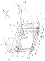
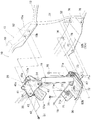
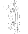
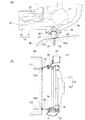
図1に示すように、車体前部構造10は、車体前部の左右側にそれぞれ設けられた左右のフロントサイドフレーム11と、左右のフロントサイドフレーム11の外側上方にそれぞれ設けられた左右のアッパメンバー12と、左右のアッパメンバー12に設けられた左右のアッパサイドフレーム13と、左右のアッパサイドフレーム13および左右のフロントサイドフレーム11に設けられたバルクヘッド15と、バルクヘッド15に設けられて冷却系部品16を支える冷却系支持ユニット20とを備えている。
As shown in FIG. 1, the vehicle
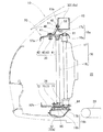
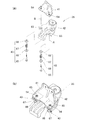
図2、図3に示すように、冷却系部品16は、エンジンルーム22に臨む部位に設けられたラジエータ17と、ラジエータ17の前方に設けられたコンデンサ18とを備えている。
コンデンサ18は、例えば、エアコン用の冷媒ガスを冷却して液化するものである。
エンジンルーム22においてラジエータ17の車体後方に吸気ダクト(エンジン補機)23およびバッテリ24が設けられている。吸気ダクト23は、エンジン25の気化器に空気を導くためのダクトである。
また、エンジンルーム22の下方に、エンジン25を支える(搭載する)サブフレーム26が設けられている。
As shown in FIGS. 2 and 3, the
For example, the
An intake duct (engine accessory) 23 and a
A
図1に示すように、左フロントサイドフレーム11は、車体前部の左側に配置され、車体前後方向に延びる部材である。
左アッパメンバー12は、左フロントサイドフレーム11の上方外側に配置され、後端部が左フロントピラー(図示せず)に連結され、前端部が左フロントサイドフレーム11の前端部11aに溶接(例えば、スポット溶接)で接合された部材である。
As shown in FIG. 1, the left
The left
左アッパサイドフレーム13は、左アッパメンバー12の略中央部12aから車体前方で、かつ車体中心側に向けてバルクヘッド15の左上端部15aまで湾曲状に延出されている。
The left
バルクヘッド15は、左右のフロントサイドフレーム11に設けられた左右のサイド脚部31と、左右のサイド脚部31の下端部31aに設けられたロア梁部32と、左右のサイド脚部31の上端部31bに設けられたアッパ梁部33とで略矩形状に形成された枠体である。
The
ロア梁部32は、左右のサイド脚部31の下端部31aに架け渡されている。
具体的には、ロア梁部32は、左サイド脚部31の下端部31aに左端部32aが溶接(例えば、スポット溶接)で接合され、右サイド脚部31の下端部31aに右端部32aが溶接(例えば、スポット溶接)で接合されている。
The
Specifically, in the
アッパ梁部33は、左右のサイド脚部31の上端部31bに架け渡されている。
具体的には、アッパ梁部33は、左サイド脚部31の上端部31bに左端部(左上端部)15aが溶接(例えば、スポット溶接)で接合され、右サイド脚部31の上端部31bに右端部(右上端部)15aが溶接(例えば、スポット溶接)で接合されている。
バルクヘッド15には、冷却系部品16を支える冷却系支持ユニット20が設けられている。
The
Specifically, the
The
冷却系支持ユニット20は、アッパ梁部33の左右の端部15aに設けられた左右の上支持機構(上支持機構)35と、ロア梁部32の左右の端部32aに設けられた左右の下支持機構(下支持機構)36とを備えている。
The cooling
冷却系支持ユニット20の車体前方側にはバンパービーム(図示せず)が設けられている。バンパービームに車体前方から後方に向けて衝撃荷重(荷重、入力)が作用することで、バンパービームに作用した衝撃荷重がバンパービームを経て冷却系支持ユニット20に伝えられる。
A bumper beam (not shown) is provided on the vehicle body front side of the cooling
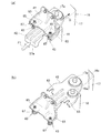
図4に示すように、左上支持機構35は、アッパ梁部33の左端部15aに設けられるとともに冷却系部品16の左上部(上部)16a(図2、図3参照)を支持可能で、かつ、冷却系部品16の左上部16aを車体後方に向けて移動可能な機構である。
左下支持機構36は、ロア梁部32の左端部32aに設けられるとともに冷却系部品16の左下部(下部)16b(図2参照)を支持可能で、かつ、冷却系部品16の左下部16bを車体後方に向けて移動可能な機構である。
As shown in FIG. 4, the upper
The lower
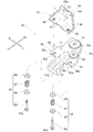
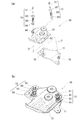
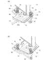
図5、図6に示すように、左上支持機構35は、アッパ梁部33の左端部15aに設けられたアッパ支持ブラケット41と、冷却系部品16の左上部16a(図2、図3参照)に設けられたアッパ移動ブラケット42と、アッパ移動ブラケット42をアッパ支持ブラケット41に締結する一対の上締結手段(上締結手段)43とを備えている。
As shown in FIGS. 5 and 6, the upper
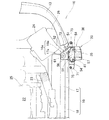
アッパ支持ブラケット41は、アッパ梁部33の左端部15aのうち前壁15bに設けられた鉛直部45と、鉛直部45の下端から車体前方に向けて下り勾配に張り出された傾斜部46(図2も参照)と、傾斜部46の前端部から車体前方に略水平に張り出された水平部47とを有する。
The
鉛直部45は、車幅方向に所定間隔をおいて一対の取付孔45aが形成されている。
鉛直部45の一対の取付孔45aにボルト51を差し込み、前壁15bの一対の溶接ナット52にねじ結合することで、鉛直部45が前壁15bに沿って一対のボルト51で取り付けられている。
この状態で、アッパ梁部33の下方で、かつ、アッパ梁部33の前方に水平部47が位置する(図2も参照)。
水平部47は、上面に一対の溶接ナット54が車幅方向に所定間隔L1をおいて溶接されている。
The
The
In this state, the
The
アッパ移動ブラケット42は、アッパ支持ブラケット41の下方で、かつ、アッパ支持ブラケット41の水平部47に沿って配置された部材である。
このアッパ移動ブラケット42は、ラジエータ17の左上部17a(図2も参照)やコンデンサ18の左上部18a(図2参照)を支えるアッパ支え部56と、アッパ支え部56から車体前方に向けて突出されたアッパ当接部57とを有する。
The upper moving
The upper moving
アッパ支え部56は、アッパ支持ブラケット41の水平部47の下方で、かつ、水平部47に沿って配置された略台形状の部位である。
このアッパ支え部56は、後端部56aに上ラジエータ支え部61が設けられ、上ラジエータ支え部61の車体前方側に上コンデンサ支え部62が設けられ、前左右端部に車幅方向に所定間隔L1をおいて一対のスリット63が形成されている。
The
The
上ラジエータ支え部61は、ラジエータ17の左上部17aに嵌合することで左上部17aを支えることができる。
上コンデンサ支え部62は、コンデンサ18の左上部18aに嵌合することで左上部18aを支えることができる。
すなわち、アッパ支え部56は、冷却系部品16の左上部16a(図2、図3参照)に設けられることで、冷却系部品16の左上部16aを支える部材である。
The upper
The upper
That is, the
一対のスリット63は、アッパ支え部56のうちアッパ支持ブラケット41に対向する部位(具体的には、水平部47の一対の溶接ナット54に対向する前左右端の部位)56bにそれぞれ設けられている。
このスリット63は、車体前方へ向けて開口するように形成され、前端に開口部63aを有するガイド溝である。
The pair of
The
スリット63に貫通された上締結ボルト65(後述する)に沿ってスリット63が車体後方に移動可能で、かつ、開口部63aが上締結ボルト65を通過することで上締結ボルト65からスリット63を外すことができる。
The
アッパ当接部57は、アッパ支え部56の前端のうち車幅方向中央(すなわち、一対のスリット63間の前端中央)56cから車体前方に向けて略水平に突出された突出片で、前端部57aが下方に折り曲げられている。
アッパ当接部57をアッパ支え部56の前端中央56cから突出させることで、アッパ当接部57の前端部57aに軽衝突時の衝撃荷重(荷重、入力)を車体前方から車体後方に向けて作用させることができる。
アッパ移動ブラケット42はアッパ支持ブラケット41に一対の上締結手段43で締結されている。
The
By causing the
The upper moving
一対の上締結手段43は、アッパ当接部57に対して一方の上締結手段43が車体外側に設けられ、アッパ当接部57に対して他方の上締結手段43が車体内側(車体中心側)に設けられている。
The pair of upper fastening means 43 is provided such that one upper fastening means 43 is provided outside the vehicle body with respect to the upper abutting
一方の上締結手段43は、アッパ移動ブラケット42をアッパ支持ブラケット41に締結する上締結ボルト(上締結部材)65と、上締結ボルト65に嵌合された第1ワッシャ66、上ばね部材(上弾性部材)67および第2ワッシャ68とを備えている。
他方の上締結手段43は、一方の上締結手段43と同一構成部材なので各構成部材に一方の上締結手段43の同じ符号を付して詳しい説明を省略する。
One upper fastening means 43 includes an upper fastening bolt (upper fastening member) 65 for fastening the upper moving
Since the other upper fastening means 43 is the same constituent member as the one upper fastening means 43, the same reference numerals of the one upper fastening means 43 are given to the respective constituent members, and detailed description thereof is omitted.
図6、図7に示すように、一方の上締結手段43は、上締結ボルト65に第1ワッシャ66、上ばね部材67および第2ワッシャ68を嵌合させた状態で、上締結ボルト65が一方(車体外側)のスリット63を貫通して一方(車体外側)の溶接ナット54にねじ結合されている。
上ばね部材67は圧縮ばねである。
As shown in FIGS. 6 and 7, one upper fastening means 43 is configured such that the
The
この状態で、第1ワッシャ66が上締結ボルト65の頭部65aに当接され、第2ワッシャ68がアッパ支え部56の前左端部56bに当接され、第1ワッシャ66および第2ワッシャ68間に上ばね部材67が圧縮された状態で介在されている。
換言すれば、上ばね部材67は、アッパ支え部56の前左端部56bおよび上締結ボルト65の頭部65aに第1ワッシャ66および第2ワッシャ68を介して圧縮された状態で介在されている。
In this state, the
In other words, the
他方の上締結手段43は、一方の上締結手段43と同様に、第1ワッシャ66が上締結ボルト65の頭部65aに当接され、第2ワッシャ68がアッパ支え部56の前右端部56bに当接され、第1ワッシャ66および第2ワッシャ68間に上ばね部材67が圧縮された状態で介在されている。
換言すれば、他方の上締結手段43の上ばね部材67は、アッパ支え部56の前右端部56bおよび上締結ボルト65の頭部65aに第1ワッシャ66および第2ワッシャ68を介して圧縮された状態で介在されている。
In the other upper fastening means 43, similarly to the one upper fastening means 43, the
In other words, the
このように、一方の上締結手段43がアッパ当接部57に対して車体外側に設けられ、他方の上締結手段43がアッパ当接部57に対して車体内側(車体中心側)に設けられることで、一対の上締結手段43がアッパ移動ブラケット42の車幅方向両側に設けられている。
In this way, one upper fastening means 43 is provided outside the vehicle body with respect to the
この状態で、一対のスリット63に上締結ボルト65がそれぞれ貫通されている。
よって、アッパ支持ブラケット41にアッパ移動ブラケット42が一対の上締結手段43で車体後方に移動自在に締結されている。
これにより、アッパ梁部33(前壁15b)に左上支持機構35を介して冷却系部品16の左上部16a(図2、図3参照)が車体後方に移動自在に設けられる。
In this state, the
Therefore, the upper moving
Thereby, the upper
アッパ移動ブラケット42の車幅方向両側(車体外側および車体中心側)に上締結手段43をそれぞれ設けることで、アッパ移動ブラケット42の車体前後方向略中央に一対の上締結手段43を備えることができる。
よって、アッパ移動ブラケット42の形状を車体後方に大きく張り出す必要がなく、アッパ移動ブラケット42の小型化を図ることができる。
By providing the upper fastening means 43 on both sides of the upper moving
Therefore, it is not necessary to project the shape of the upper moving
このように、アッパ移動ブラケット42の小型化を図り、かつ、アッパ移動ブラケット42を所望方向(車体後方)に安定的にスライド移動させることで、アッパ移動ブラケット42の車体後方への突出方向や突出量を好適に抑えることができる。
In this way, the upper moving
さらに、アッパ移動ブラケット42および上締結ボルト65の頭部65a間に上ばね部材67を介在させることで、上締結ボルト65の締結荷重を上ばね部材67で好適に調整することができる。
これにより、アッパ移動ブラケット42のスリット63を上締結ボルト65から外す際の荷重(すなわち、「抜去荷重」)の管理が容易になり、性能品質を良好に保つことができる。
Further, by interposing the
This facilitates management of the load (ie, “extraction load”) when the
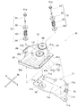
図5、図8に示すように、左下支持機構36は、ロア梁部32の左端部32aに設けられたロア支持ブラケット71と、冷却系部品16の左下部16b(図2参照)に設けられたロア移動ブラケット72と、ロア移動ブラケット72をロア支持ブラケット71に締結する一対の下締結手段(下締結手段)73とを備えている。
As shown in FIGS. 5 and 8, the lower
ロア支持ブラケット71は、ロア梁部32の左端部32aのうち上部32bに沿って設けられ、平面視で略四角形に形成されている。
このロア支持ブラケット71は、四隅に取付孔71aがそれぞれ形成されている。
四隅の取付孔71aにボルト75をそれぞれ差し込み、上部32bの溶接ナット76にねじ結合することで、ロア支持ブラケット71が上部32bに4個のボルト75で取り付けられる。
The
The
The
この状態で、ロア支持ブラケット71のブラケット本体71bが上部32bに対して上方に浮いた状態で配置される(図9も参照)。
ブラケット本体71bは、車体中心側部71cに溶接ナット78が溶接され、車体外側部71dに溶接ナット78が溶接されている。
車体中心側部71cの溶接ナット78および車体外側部71dの溶接ナット78は、車幅方向に所定間隔L2をおいて溶接されている。
In this state, the bracket
In the
The
ロア移動ブラケット72は、ロア支持ブラケット71の上方で、かつ、ロア支持ブラケット71に沿って配置されている。
このロア移動ブラケット72は、ラジエータ17の左下部17b(図2参照)やコンデンサ18の左下部18b(図2参照)を支えるロア支え部81と、ロア支え部81から車体前方に向けて突出されたロア当接部82とを有する。
The lower moving
The lower moving
ロア支え部81は、ロア支持ブラケット71の上方で、かつ、ロア支持ブラケット71に沿って配置された略矩形状の部位である。
このロア支え部81は、後端部81aに下ラジエータ支え部84が設けられ、下ラジエータ支え部84の車体前方側に下コンデンサ支え部85が設けられ、車体中心側部81bにスリット86が形成され、外側部81cにスロット穴87の後半部87aが形成されている。
The
In the
下ラジエータ支え部84は、ラジエータ17の左下部17bに嵌合することで左下部17bを支えることができる。
下コンデンサ支え部85は、コンデンサ18の左下部18bに嵌合することで左下部18bを支えることができる。
すなわち、ロア移動ブラケット72は冷却系部品16の左下部16b(図2参照)に設けられることで、冷却系部品16の左下部16bを支える部材である。
The lower
The lower
That is, the lower moving
スリット86は、ロア支持ブラケット71(車体中心側部71c)の溶接ナット78に対向する部位(車体中心側部)81bに設けられている。
このスリット86は、車体前方へ向けて開口するように形成され、前端に開口部86aを有するガイド溝である。
スリット86に貫通された下締結ボルト91(後述する)に沿ってスリット86が車体後方に移動可能で、かつ、開口部86aが下締結ボルト91を通過することで下締結ボルト91からスリット86を外すことができる。
The
The
The
スロット穴87の後半部87aは、ロア支持ブラケット71(車体外側部71d)の溶接ナット78に対向する部位(外側部)81cに設けられ、車体前後方向へ向けて延びている。
A
ロア当接部82は、ロア支え部81の前端から車体前方に向けて略水平に突出された突出片で、外側部82aにスロット穴87の前半部87bが形成され、前端部82bが上方に折り曲げられている。
The
スロット穴87の前半部87bは、スロット穴87の後半部87aから車体前方に向けて直線上に延出されている。
前半部87bおよび後半部87aでスロット穴87が形成されている。
スロット穴87は、車体前後方向に向けて直線上に延出され、スロット穴87に貫通された下締結ボルト91(後述する)に沿って車体後方に移動可能なガイド用の長穴である。
スロット穴87およびスリット86は、車幅方向に所定間隔L2をおいて形成されている。
The
Slot holes 87 are formed in the
The
The
ロア当接部82をロア支え部81の前端から突出させることで、ロア当接部82の前端部82bに軽衝突時の衝撃荷重(荷重、入力)を車体前方から車体後方に向けて作用させることができる。
ロア移動ブラケット72はロア支持ブラケット71に一対の下締結手段73で締結されている。
By causing the
The lower moving
一対の下締結手段73は、一方の下締結手段73がスロット穴87に対応するように車体外側に設けられ、他方の下締結手段73がスリット86に対応するように車体内側(車体中心側)に設けられている。
The pair of lower fastening means 73 is provided on the outside of the vehicle body so that one lower fastening means 73 corresponds to the
一方の下締結手段73は、ロア移動ブラケット72をロア支持ブラケット71に締結する下締結ボルト(下締結部材)91と、下締結ボルト91に嵌合された第1ワッシャ92、下ばね部材(下弾性部材)93および第2ワッシャ94とを備えている。
他方の下締結手段73は、一方の下締結手段73と同一構成部材なので各構成部材に一方の下締結手段73と同じ符号を付して詳しい説明を省略する。
One lower fastening means 73 includes a lower fastening bolt (lower fastening member) 91 for fastening the lower moving
Since the other lower fastening means 73 is the same constituent member as the one lower fastening means 73, the same reference numerals as those of the one lower fastening means 73 are given to the respective constituent members, and detailed description thereof is omitted.
図8、図9に示すように、一方の下締結手段73は、下締結ボルト91に第1ワッシャ92、下ばね部材93および第2ワッシャ94を嵌合させた状態で、下締結ボルト91がスロット穴87を貫通して一方の溶接ナット78にねじ結合されている。
下ばね部材93は圧縮ばねである。
As shown in FIGS. 8 and 9, one lower fastening means 73 is configured such that the
The
この状態で、第1ワッシャ92が下締結ボルト91の頭部91aに当接され、第2ワッシャ94がロア支え部81の外側部81cに当接され、第1ワッシャ92および第2ワッシャ94間に下ばね部材93が圧縮された状態で介在されている。
換言すれば、下ばね部材93は、下締結ボルト91の頭部91aおよびロア支え部81の外側部81cに第1ワッシャ92および第2ワッシャ94を介して圧縮された状態で介在されている。
In this state, the
In other words, the
他方の下締結手段73は、下締結ボルト91に第1ワッシャ92、下ばね部材93および第2ワッシャ94を嵌合させた状態で、下締結ボルト91がスリット86を貫通して他方(車体内側(車体中心側))の溶接ナット78にねじ結合されている。
The other lower fastening means 73 is configured such that the
この他方の下締結手段73は、一方の下締結手段73と同様に、第1ワッシャ92が下締結ボルト91の頭部91aに当接され、第2ワッシャ94がロア支え部81の車体中心側部81bに当接され、第1ワッシャ92および第2ワッシャ94間に下ばね部材93が圧縮された状態で介在されている。
換言すれば、他方の下締結手段73の下ばね部材93は、下締結ボルト91の頭部91aおよびロア支え部81の車体中心側部81bに第1ワッシャ92および第2ワッシャ94を介して圧縮された状態で介在されている。
In the other lower fastening means 73, similarly to the one lower fastening means 73, the
In other words, the
このように、一方の下締結手段73がロア移動ブラケット72の外側部81cに設けられ、他方の下締結手段73がロア移動ブラケット72の車体中心側部81bに設けられることで、一対の下締結手段73がロア移動ブラケット72の車幅方向両側に設けられている。
As described above, one lower fastening means 73 is provided on the
この状態で、スリット86に下締結ボルト91が貫通されるとともに、スロット穴87に下締結ボルト91が貫通されている。
よって、ロア支持ブラケット71にロア移動ブラケット72が一対の下締結手段73で車体後方に移動自在に締結されている。
これにより、ロア梁部32(上部32b)に左下支持機構36を介して冷却系部品16の左下部16b(図2参照)が車体後方に移動自在に設けられる。
In this state, the
Therefore, the lower moving
Thus, the lower
ここで、スロット穴87は車体前後方向に延出されている。
これにより、ロア移動ブラケット72を車体後方に移動(スライド移動)させる際に、スロット穴87を下締結ボルト91に沿わせて移動させることができる。
Here, the
As a result, when the lower moving
ロア移動ブラケット72の車幅方向両側に下締結手段73をそれぞれ設けることで、ロア移動ブラケット72の車体前後方向略中央に一対の下締結手段73を備えることができる。
よって、ロア移動ブラケット72の形状を車体後方に大きく張り出す必要がなく、ロア移動ブラケット72の小型化を図ることができる。
By providing the lower fastening means 73 on both sides of the lower moving
Therefore, it is not necessary to project the shape of the lower moving
このように、ロア移動ブラケット72の小型化を図り、かつ、ロア移動ブラケット72を所望方向(車体後方)に安定的にスライド移動させることで、ロア移動ブラケット72の車体後方への突出方向や突出量を好適に抑えることができる。
As described above, the lower moving
さらに、ロア移動ブラケット72および下締結ボルト91の頭部91a間に下ばね部材93を介在させることで、下締結ボルト91の締結荷重を下ばね部材93で好適に調整することができる。
これにより、ロア移動ブラケット72のスリット86を下締結ボルト91から外す際の荷重(すなわち、「抜去荷重」)の管理が容易になり、性能品質を良好に保つことができる。
さらに、ロア移動ブラケット72のスロット穴87を下締結ボルト91に沿わせて移動する際の荷重(すなわち、「移動荷重」)の管理が容易になり、性能品質を良好に保つことができる。
Further, by interposing the
Thereby, management of the load (namely, "extraction load") at the time of removing the
Furthermore, the load (ie, “moving load”) when moving the
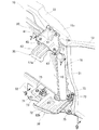
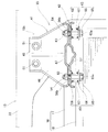
図4に示すように、車体前部構造10によれば、アッパ梁部33に上支持機構35を設け、この左上支持機構35で冷却系部品16の左上部16a(図2、図3参照)を支持可能で、かつ、車体後方に向けて移動可能とした。
また、ロア梁部32に左下支持機構36を設け、この左下支持機構36で冷却系部品16の左下部16b(図2参照)を支持可能で、かつ、車体後方に向けて移動可能とした。
As shown in FIG. 4, according to the vehicle
Further, a lower
よって、左上支持機構35および左下支持機構36に衝撃荷重が車体前方から作用した際に、各支持機構35,36で冷却系部品16を車体後方に向けて移動させることができる。
これにより、冷却系部品16を車体後方に向けて移動させて、冷却系部品16が衝撃荷重で損傷することを防ぐことができる。
Therefore, when an impact load is applied to the upper
Thereby, it is possible to prevent the
さらに、アッパ梁部33の左上支持機構35およびロア梁部32の左下支持機構36で冷却系部品16を車体後方に向けて移動可能とさせることで、アッパ梁部やロア梁部を車体後方に移動させる必要がない。
アッパ梁部33やロア梁部32を車体後方に移動させる必要がないので、アッパ梁部33やロア梁部32を一体的に強固に設けて(取り付けて)フロントバルクヘッド15の剛性を確保できる。
これにより、フロントバルクヘッド15で車体前部構造10の剛性を確保することが可能になり、車体前部構造10を多種のパワーユニット(例えば、エンジン・トランスミッションユニット)に対応させることができる。
Further, by allowing the
Since it is not necessary to move the
Thus, the rigidity of the vehicle
つぎに、車体前部構造10の製造方法(組付手順)を図10〜図12に基づいて説明する。
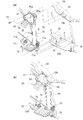
図10(a)に示すように、一方の上締結手段43の上締結ボルト65に第1ワッシャ66、上ばね部材67および第2ワッシャ68を嵌合させる。
この状態で、上締結ボルト65をアッパ移動ブラケット42の一方(車体外側)のスリット63に貫通させて、アッパ支持ブラケット41の一方(車体外側)の溶接ナット54に矢印Aの如くねじ結合する。
Next, a manufacturing method (assembly procedure) of the vehicle
As shown in FIG. 10A, the
In this state, the
また、他方の上締結手段43の上締結ボルト65に第1ワッシャ66、上ばね部材67および第2ワッシャ68を嵌合させる。
この状態で、上締結ボルト65をアッパ移動ブラケット42の他方(車体内側(車体中心側))のスリット63に貫通させてアッパ支持ブラケット41の他方(車体内側(車体中心側))の溶接ナット54に矢印Bの如くねじ結合する。
Further, the
In this state, the
図10(b)に示すように、アッパ支持ブラケット41にアッパ移動ブラケット42を一対の上締結手段43で車体後方に移動自在に締結する。
As shown in FIG. 10B, the upper moving
図11(a)に示すように、一方の下締結手段73の下締結ボルト91に第1ワッシャ92、下ばね部材93および第2ワッシャ94を嵌合させる。
この状態で、下締結ボルト91をロア移動ブラケット72のスロット穴87に貫通させてロア支持ブラケット71の一方(車体外側)の溶接ナット78に矢印Cの如くねじ結合する。
As shown in FIG. 11A, the
In this state, the
また、他方の下締結手段73の下締結ボルト91に第1ワッシャ92、下ばね部材93および第2ワッシャ94を嵌合させる。
この状態で、下締結ボルト91をロア移動ブラケット72のスリット86に貫通させてロア支持ブラケット71の他方(車体内側(車体中心側))の溶接ナット78に矢印Dの如くねじ結合する。
Further, the
In this state, the
図11(b)に示すように、ロア支持ブラケット71にロア移動ブラケット72を一対の上締結手段73で車体後方に移動自在に締結する。
As shown in FIG. 11B, a lower moving
図12(a)に示すように、アッパ支持ブラケット41にアッパ移動ブラケット42を締結した状態で、アッパ移動ブラケット42に冷却系部品16の左上部16a(図2、図3参照)を支持する。
さらに、ロア支持ブラケット71にロア移動ブラケット72を締結した状態で、ロア移動ブラケット72に冷却系部品16の左下部16bを支持する。
As illustrated in FIG. 12A, the upper
Further, the lower
アッパ移動ブラケット42に冷却系部品16の左上部16aを支持した状態において、アッパ支持ブラケット41の一対の取付孔45aにボルト51を差し込む。
そして、差し込んだ一対のボルト51をアッパ梁部33(前壁15b)の溶接ナット52に矢印Eの如くそれぞれねじ結合する。
In a state where the upper
The pair of
さらに、ロア移動ブラケット72に冷却系部品16の左下部16b(図2参照)を支持した状態において、ロア支持ブラケット71の四隅の取付孔71aにボルト75をそれぞれ差し込む。
そして、差し込んだ4個のボルト75をロア梁部32(上部32b)の溶接ナット76に矢印Fの如くねじ結合する。
Further, in a state where the lower left
Then, the four inserted
図12(b)に示すように、アッパ支持ブラケット41をアッパ梁部33(前壁15b)に一対のボルト51で取り付ける。
これにより、アッパ梁部33(前壁15b)に左上支持機構35を介して冷却系部品16の左上部16a(図2、図3参照)が車体後方に移動自在に設けられる。
As shown in FIG. 12B, the
Thereby, the upper
さらに、ロア支持ブラケット71をロア梁部32(上部32b)に4個のボルト75で取り付ける。
これにより、ロア梁部32(上部32b)に左下支持機構36を介して冷却系部品16の左下部16bが車体後方に移動自在に設けられる。
Further, the
Thus, the lower
このように、アッパ梁部33にアッパ支持ブラケット41を取り付ける前に、アッパ支持ブラケット41にアッパ移動ブラケット42を一対の上締結手段43で締結した。
よって、アッパ支持ブラケット41にアッパ移動ブラケット42を一対の上締結手段43で締結する際の締結荷重(すなわち、「抜去荷重」)を好適に調整することができる。
As described above, the upper moving
Therefore, the fastening load (that is, “extraction load”) when the upper moving
同様に、ロア梁部32にロア支持ブラケット71を取り付ける前に、ロア支持ブラケット71にロア移動ブラケット72を一対の下締結手段73で締結した。
よって、ロア支持ブラケット71にロア移動ブラケット72を一対の下締結手段73で締結する際の締結荷重(すなわち、「移動荷重」)を好適に調整することができる。
Similarly, before attaching the
Therefore, the fastening load (that is, “moving load”) when the lower moving
このように、上下の締結手段43,73の締結荷重を好適に調整することで、締結荷重の管理が容易になり、性能品質を良好に保つことができる。
したがって、フロントバルクヘッド15に左上支持機構35および左下支持機構36を介して冷却系部品16を容易に組み付けることができる。
Thus, by suitably adjusting the fastening loads of the upper and lower fastening means 43, 73, the fastening load can be easily managed and the performance quality can be kept good.
Therefore, the
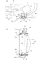
つぎに、車体前部構造10の左前部に障害物98が軽衝突(オフセット衝突)した場合に、冷却系部品16の左半部を車体後方に移動させる例を図13〜図17に基づいて説明する。
図13(a),(b)に示すように、車体前部構造10の左前部に障害物98が軽衝突した場合に、左上支持機構35のアッパ当接部57(前端部57a)に衝撃荷重F1が矢印の如く伝わる。
同時に、左下支持機構36のロア当接部82(前端部82b)に衝撃荷重F2が矢印の如く伝わる。
Next, an example in which the left half of the
As shown in FIGS. 13A and 13B, when the
At the same time, the impact load F2 is transmitted to the lower contact portion 82 (
ここで、図14(a)に示すように、アッパ移動ブラケット42の一対のスリット63が車体前方へ向けて開口されている(図14(b)も参照)。
そして、スリット63を貫通した上締結ボルト65で上ばね部材67が圧縮されている。よって、アッパ移動ブラケット42が一対の上締結手段43でアッパ支持ブラケット41に締結されている。
これにより、アッパ移動ブラケット42の前端部57aに衝撃荷重F1が伝わることにより、アッパ移動ブラケット42が車体後方に向けて矢印Gの如く移動(スライド移動)する。
Here, as shown in FIG. 14A, the pair of
The
As a result, the impact load F1 is transmitted to the
図14(b)に示すように、アッパ移動ブラケット42を車体後方に移動させることで、一方の上締結ボルト65から一方(車体外側)のスリット63を外すとともに、他方の上締結ボルト65から他方(車体内側(車体中心側))のスリット63を外すことができる。
As shown in FIG. 14B, the upper moving
また、図15(a)に示すように、ロア移動ブラケット72のスロット穴87が車体前後方向へ向けて延出されている。
さらに、ロア移動ブラケット72のスリット86が車体前方へ向けて開口されている(図11(a)も参照)。
そして、スロット穴87を貫通した一方の下締結ボルト91で一方の下ばね部材93が圧縮されている。また、スリット86を貫通した他方の下締結ボルト91で他方の下ばね部材93が圧縮されている。
Further, as shown in FIG. 15A, the
Further, the
One
よって、ロア移動ブラケット72が一対の下締結手段73でロア支持ブラケット71に締結されている。
これにより、ロア移動ブラケット72の前端部82bに衝撃荷重F2が伝わることにより、ロア移動ブラケット72が車体後方に向けて矢印Hの如く移動(スライド移動)する。
Therefore, the lower moving
As a result, the impact load F2 is transmitted to the
図15(b)に示すように、ロア移動ブラケット72を車体後方に移動させた際に、スリット86を他方の下締結ボルト91から外し、スロット穴87に一方の下締結ボルト91を貫通させた状態に保つことができる。
すなわち、ロア移動ブラケット72がロア支持ブラケット71から離れないように一方の下締結ボルト91で保持することができる。
As shown in FIG. 15 (b), when the lower moving
That is, the lower moving
図16(a),(b)に示すように、アッパ移動ブラケット42を車体後方に向けて矢印Gの如く移動(スライド移動)することで、冷却系部品16の左上部16a(図2、図3参照)を車体後方に向けて矢印Gの如く移動することができる。
さらに、ロア移動ブラケット72を車体後方に向けて矢印Hの如く移動(スライド移動)することで、冷却系部品16の左下部16b(図2参照)を車体後方に向けて矢印Hの如く移動することができる。
これにより、冷却系部品16の左半部を車体後方に向けて移動することができる。
As shown in FIGS. 16A and 16B, the upper moving
Further, by moving the lower moving
Thereby, the left half part of the
ここで、図14(a),(b)に示すように、アッパ移動ブラケット42を車体後方に向けて矢印Gの如く移動(スライド移動)することで、一対の上締結ボルト65からスリット63をそれぞれ外すことができる。
これにより、冷却系部品16の左上部16a(図2、図3参照)をアッパ支持ブラケット41(アッパ梁部33(図4参照))から外して、冷却系部品16の左上部16aの拘束を解除できる。
Here, as shown in FIGS. 14A and 14B, the upper moving
As a result, the left
また、図15(a),(b)に示すように、ロア移動ブラケット72を車体後方に向けて矢印Hの如く移動(スライド移動)させた際に、ロア移動ブラケット72がロア支持ブラケット71(ロア梁部32)から離れないように一方の下締結ボルト91で保持できる。
Further, as shown in FIGS. 15A and 15B, when the lower moving
図17(a),(b)に示すように、冷却系部品16をロア移動ブラケット72(すなわち、冷却系部品16の左下部16b(図2参照))を支点として車体後方に向けて矢印Gの如く比較的大きく移動させることができる。
これにより、冷却系部品16の左上部16a(図2、図3参照)が衝撃荷重で損傷することを良好に防ぐことができる。
As shown in FIGS. 17A and 17B, the
Thereby, it can prevent favorably that the upper
さらに、アッパ移動ブラケット42をアッパ梁部33(アッパ支持ブラケット41)から外すことで、アッパ梁部33に衝撃荷重が作用することを除去できる。
これにより、アッパ梁部33(すなわち、フロントバルクヘッド15)が衝撃荷重で変形することを抑えることができ、修理費(リペア費)を低減することができる。
Further, by removing the upper moving
Thereby, it can suppress that the upper beam part 33 (namely, front bulkhead 15) deform | transforms with an impact load, and can reduce repair cost (repair cost).
また、ロア移動ブラケット72をロア支持ブラケット71に連結させた状態に保つことで、冷却系部品16の左下部16b(図2参照)を所望方向に安定的に移動させることができる。
そして、冷却系部品16の左下部16bの移動が完了した際に、冷却系部品16をフロントバルクヘッド15から離れないように保つことができる。
これにより、冷却系部品16を良好に保護して冷却系部品16の衝撃荷重による損傷を一層良好に防ぐことができる。
Further, by keeping the lower moving
Then, when the movement of the lower
As a result, the
ここで、図14(a),(b)に示すように、アッパ移動ブラケット42の車幅方向両側に上締結手段43をそれぞれ設けた。よって、アッパ移動ブラケット42を所望方向(車体後方)に安定的に移動(スライド移動)させることができる。
さらに、アッパ移動ブラケット42の車幅方向両側に上締結手段43を設けた。一対の上締結手段43はアッパ移動ブラケット42の車体前後方向略中央に設けられている。
よって、アッパ移動ブラケット42の形状を車体後方に大きく張り出す必要がなく、アッパ移動ブラケット42の小型化を図ることができる。
Here, as shown in FIGS. 14A and 14B, upper fastening means 43 are provided on both sides of the upper moving
Further, upper fastening means 43 are provided on both sides of the upper moving
Therefore, it is not necessary to project the shape of the upper moving
加えて、図15(a),(b)に示すように、ロア移動ブラケット72の車幅方向両側に下締結手段73をそれぞれ設けた。よって、ロア移動ブラケット72を所望方向(車体後方)に安定的に移動(スライド移動)させることができる。
さらに、ロア移動ブラケット72の車幅方向両側に下締結手段73を設けた。一対の下締結手段73はロア移動ブラケット72の車体前後方向略中央に設けられている。
よって、ロア移動ブラケット72の形状を車体後方に大きく張り出す必要がなく、ロア移動ブラケット72の小型化を図ることができる。
In addition, as shown in FIGS. 15A and 15B, lower fastening means 73 are provided on both sides of the lower moving
Further, lower fastening means 73 are provided on both sides of the lower moving
Therefore, it is not necessary to project the shape of the lower moving
図17(a),(b)に示すように、アッパ移動ブラケット42およびロア移動ブラケット72を所望方向(車体後方)に安定的にスライド移動させることで、冷却系部品16を車体後方に安定的に移動させることができる。
さらに、アッパ移動ブラケット42およびロア移動ブラケット72の小型化を図ることで、アッパ移動ブラケット42およびロア移動ブラケット72の車体後方への突出方向や突出量を好適に抑えることができる。
As shown in FIGS. 17A and 17B, the
Further, by downsizing the upper moving
これにより、図17(a)に示すように、冷却系部品16を車体後方に移動させた際に、冷却系部品16の後方に備えられたバッテリ24にアッパ移動ブラケット42や冷却系部品16が干渉することを良好に避ける(回避する)ことができる。
さらに、図17(b)に示すように、エンジンルーム22の下方に備えたサブフレーム26にロア移動ブラケット72や冷却系部品16が干渉することを良好に避ける(回避する)ことができる。
Thus, as shown in FIG. 17A, when the
Further, as shown in FIG. 17B, it is possible to favorably avoid (avoid) interference of the lower moving
ここで、図17(a)に示すように、冷却系部品16を車体後方に移動させた際に、冷却系部品16の後方に備えられた吸気ダクト23に冷却系部品16が干渉することが考えられる。
この吸気ダクト23は弾性変形可能な部材である。よって、吸気ダクト23に冷却系部品16が干渉した際に、吸気ダクト23が弾性変形して冷却系部品16が損傷することを防ぐことができる。
Here, as shown in FIG. 17A, when the
This
なお、本発明に係る車体前部構造10および車体前部構造10の製造方法は、前述した実施例に限定されるものではなく適宜変更、改良などが可能である。
例えば、前記実施例では、上下の弾性部材として上下のばね部材67,93を用いた例について説明したが、これに限らないで、硬質ゴムなどの他の弾性部材を用いることも可能である。
It should be noted that the vehicle
For example, in the above-described embodiment, the example in which the upper and
また、前記実施例では、上締結手段43の一部構成部材として上締結ボルト65および第1ワッシャ66の2部材を用いた例について説明したが、これに限らないで、上締結ボルト65および第1ワッシャ66を一体にまとめた、通称「フランジボルト」と称されるボルトを使用することも可能である。
加えて、下締結手段73の一部構成部材として下締結ボルト91および第1ワッシャ92の2部材を用いた例について説明したが、これに限らないで、下締結ボルト91および第1ワッシャ92を一体にまとめた、通称「フランジボルト」と称されるボルトを使用することも可能である。
上締結手段43や下締結手段73に「フランジボルト」を用いることで組立の一層の容易化を図ることができる。
In the above-described embodiment, an example in which two members of the
In addition, the example in which the two members of the
By using “flange bolts” for the upper fastening means 43 and the lower fastening means 73, the assembly can be further facilitated.
さらに、前記実施例では、車体前部構造10の左前部に障害物98が軽衝突(オフセット衝突)した場合について説明したが、これに限らないで、車体前部構造10の右前部に障害物98が軽衝突(オフセット衝突)した場合でも同様の効果を得ることができる。
加えて、車体前部構造10の前部に障害物98が正面衝突(軽衝突)した場合でも同様の効果を得ることができる。
Further, in the above-described embodiment, the case where the
In addition, the same effect can be obtained even when the
また、前記実施例では、左上支持機構35のアッパ移動ブラケット42や左下支持機構36のロア移動ブラケット72に軽衝突時の衝撃荷重が作用した例について説明したが、これに限らないで、軽衝突時の衝撃荷重より大きな荷重が作用した場合でも同様の効果を得ることができる。
In the above-described embodiment, an example in which an impact load at the time of a light collision is applied to the upper moving
さらに、前記実施例では、左上支持機構35に一対(2個)の上締結手段43を設けた例について説明したが、これに限らないで、上締結手段43を2個以上の複数個設けることも可能である。
加えて、左下支持機構36に一対(2個)の下締結手段73を設けた例について説明したが、これに限らないで、下締結手段73を2個以上の複数個設けることも可能である。
Furthermore, in the above-described embodiment, an example in which a pair (two) of upper fastening means 43 is provided in the upper
In addition, an example in which a pair of (two) lower fastening means 73 is provided in the lower
また、前記実施例で示した車体前部構造10、フロントバルクヘッド15、冷却系部品16、左上部16a、左下部16b、ロア梁部32、アッパ梁部33、左右の上支持機構35、左右の下支持機構36、アッパ支持ブラケット41、アッパ移動ブラケット42、上締結手段43、アッパ当接部57、スリット63,86、上締結ボルト65、上ばね部材67、ロア支持ブラケット71、ロア移動ブラケット72、下締結手段73、ロア当接部82、スロット穴87、下締結ボルト91および下ばね部材93などの形状や構成は例示したものに限定するものではなく適宜変更が可能である。
Further, the vehicle
本発明は、フロントバルクヘッドのアッパ梁部に冷却系部品の上部が設けられるとともにロア梁部に冷却系部品の下部が設けられた自動車への適用に好適である。 The present invention is suitable for application to an automobile in which an upper beam portion of a front bulkhead is provided with an upper portion of a cooling system component and a lower beam portion is provided with a lower portion of the cooling system component.
10…車体前部構造、15…フロントバルクヘッド、16…冷却系部品、16a…左上部(上部)、16b…左下部(下部)、32…ロア梁部、33…アッパ梁部、35…左右の上支持機構(上支持機構)、36…左右の下支持機構(下支持機構)、41…アッパ支持ブラケット、42…アッパ移動ブラケット、43…上締結手段(上締結手段)、56b…アッパ支持ブラケットに対向する部位、57…アッパ当接部、63,86…スリット、65…上締結ボルト(上締結部材)、67…上ばね部材(上弾性部材)、71…ロア支持ブラケット、72…ロア移動ブラケット、73…下締結手段(下締結手段)、81c…ロア支持ブラケットに対向する部位、82…ロア当接部、87…スロット穴、91…下締結ボルト(下締結部材)、93…下ばね部材(下弾性部材)。
DESCRIPTION OF
Claims (3)
前記アッパ梁部に設けられるとともに前記冷却系部品の上部を支持可能で、かつ、前記冷却系部品の上部を車体後方に向けて移動可能な上支持機構と、
前記ロア梁部に設けられるとともに前記冷却系部品の下部を支持可能で、かつ、前記冷却系部品の下部を車体後方に向けて移動可能な下支持機構と、
を備え、
前記上支持機構は、
前記アッパ梁部に設けられたアッパ支持ブラケットと、
前記アッパ支持ブラケットに対向する部位に車体前方へ向けて開口するスリットが形成されるとともに、前記冷却系部品の上部に設けられたアッパ移動ブラケットと、
前記アッパ移動ブラケットを前記アッパ支持ブラケットに締結するために前記スリットに貫通された上締結部材を有する上締結手段と、
を備え、
前記上締結手段は、
前記アッパ移動ブラケットおよび前記上締結部材間に介在させた上弾性部材を有し、
前記下支持機構は、
前記ロア梁部に設けられたロア支持ブラケットと、
前記ロア支持ブラケットに対向する部位に車体前後方向へ向けて延びるスロット穴が形成されるとともに、前記冷却系部品の下部に設けられたロア移動ブラケットと、
前記ロア移動ブラケットを前記ロア支持ブラケットに締結するために前記スロット穴に貫通された下締結部材を有する下締結手段と、
を備え、
前記下締結手段は、
前記ロア移動ブラケットおよび前記下締結部材間に介在させた下弾性部材を有し、
前記アッパ支持ブラケットに前記アッパ移動ブラケットが前記上締結手段で締結された状態で、前記アッパ移動ブラケットおよび前記アッパ支持ブラケットを、それぞれ前記冷却系部品の上部および前記アッパ梁部に取付可能とし、
前記ロア支持ブラケットに前記ロア移動ブラケットが前記下締結手段で締結された状態で、前記ロア移動ブラケットおよび前記ロア支持ブラケットを、それぞれ前記冷却系部品の下部および前記ロア梁部に取付可能とし、
前記アッパ移動ブラケットに前記スリットが形成され、かつ、前記ロア移動ブラケットに前記スロット穴が形成されることにより、前記アッパ移動ブラケット、前記ロア移動ブラケットに衝撃荷重が作用した際に、前記スリットを前記上締結部材から外した状態で、前記スロット穴を前記下締結部材に沿って移動可能としたことを特徴とする車体前部構造。 In the vehicle body front structure in which an upper beam part of the front bulkhead is provided with an upper part of the cooling system part and a lower part of the cooling system part is provided in the lower beam part of the front bulkhead,
An upper support mechanism that is provided on the upper beam part and can support the upper part of the cooling system part, and can move the upper part of the cooling system part toward the rear of the vehicle body;
A lower support mechanism that is provided in the lower beam part and can support the lower part of the cooling system part and can move the lower part of the cooling system part toward the rear of the vehicle body;
Equipped with a,
The upper support mechanism is
An upper support bracket provided on the upper beam portion;
A slit that opens toward the front of the vehicle body is formed at a portion facing the upper support bracket, and an upper moving bracket provided on the upper part of the cooling system component;
Upper fastening means having an upper fastening member penetrated by the slit for fastening the upper moving bracket to the upper support bracket;
With
The upper fastening means includes
An upper elastic member interposed between the upper moving bracket and the upper fastening member;
The lower support mechanism is
A lower support bracket provided on the lower beam portion;
A slot hole extending in the longitudinal direction of the vehicle body is formed at a portion facing the lower support bracket, and a lower moving bracket provided at a lower portion of the cooling system component,
Lower fastening means having a lower fastening member penetrated through the slot hole for fastening the lower moving bracket to the lower support bracket;
With
The lower fastening means includes
A lower elastic member interposed between the lower moving bracket and the lower fastening member;
With the upper moving bracket being fastened to the upper support bracket by the upper fastening means, the upper moving bracket and the upper support bracket can be attached to the upper part of the cooling system component and the upper beam part, respectively.
With the lower moving bracket being fastened to the lower support bracket by the lower fastening means, the lower moving bracket and the lower support bracket can be attached to the lower part of the cooling system component and the lower beam part, respectively.
When the slit is formed in the upper moving bracket and the slot hole is formed in the lower moving bracket, when the impact load is applied to the upper moving bracket and the lower moving bracket, the slit is The vehicle body front part structure , wherein the slot hole is movable along the lower fastening member in a state where it is removed from the upper fastening member .
前記アッパ移動ブラケットの車幅方向両側に前記上締結手段が設けられたことを特徴とする請求項1の車体前部構造。 The upper moving bracket has an upper contact portion on which a load acts toward the rear of the vehicle body,
Front body structure of claim 1, characterized in that the upper fastening means in the vehicle width direction on both sides of the upper movable bracket is provided.
前記ロア移動ブラケットの車幅方向両側に前記下締結手段が設けられたことを特徴とする請求項1記載の車体前部構造。 The lower moving bracket has a lower abutting portion on which a load acts toward the rear of the vehicle body,
Front body structure of claim 1, wherein said lower fastening means in the vehicle width direction on both sides of the lower movable bracket is provided.
Priority Applications (3)
| Application Number | Priority Date | Filing Date | Title |
|---|---|---|---|
| JP2010132200A JP5073785B2 (en) | 2010-06-09 | 2010-06-09 | Vehicle body front structure and method for manufacturing vehicle body front structure |
| US13/154,664 US8403404B2 (en) | 2010-06-09 | 2011-06-07 | Vehicle body front structure and manufacturing method thereof |
| EP11168909A EP2394885B1 (en) | 2010-06-09 | 2011-06-07 | Vehicle body front structure and manufacturing method thereof |
Applications Claiming Priority (1)
| Application Number | Priority Date | Filing Date | Title |
|---|---|---|---|
| JP2010132200A JP5073785B2 (en) | 2010-06-09 | 2010-06-09 | Vehicle body front structure and method for manufacturing vehicle body front structure |
Publications (2)
| Publication Number | Publication Date |
|---|---|
| JP2011255794A JP2011255794A (en) | 2011-12-22 |
| JP5073785B2 true JP5073785B2 (en) | 2012-11-14 |
Family
ID=45472472
Family Applications (1)
| Application Number | Title | Priority Date | Filing Date |
|---|---|---|---|
| JP2010132200A Expired - Fee Related JP5073785B2 (en) | 2010-06-09 | 2010-06-09 | Vehicle body front structure and method for manufacturing vehicle body front structure |
Country Status (1)
| Country | Link |
|---|---|
| JP (1) | JP5073785B2 (en) |
Families Citing this family (2)
| Publication number | Priority date | Publication date | Assignee | Title |
|---|---|---|---|---|
| JP5692187B2 (en) * | 2012-08-30 | 2015-04-01 | トヨタ自動車株式会社 | Body front structure |
| JP6175336B2 (en) * | 2013-09-30 | 2017-08-02 | 株式会社Subaru | Vehicle with electric drive device |
Family Cites Families (4)
| Publication number | Priority date | Publication date | Assignee | Title |
|---|---|---|---|---|
| DE102005037912A1 (en) * | 2005-08-10 | 2007-02-15 | Audi Ag | Storage for a cooler |
| JP2007055543A (en) * | 2005-08-26 | 2007-03-08 | Kojima Press Co Ltd | Pedestrian protecting device for vehicle |
| JP4499133B2 (en) * | 2006-11-01 | 2010-07-07 | カルソニックカンセイ株式会社 | Heat exchanger support structure |
| JP4781343B2 (en) * | 2007-12-07 | 2011-09-28 | 本田技研工業株式会社 | Vehicle front structure |
-
2010
- 2010-06-09 JP JP2010132200A patent/JP5073785B2/en not_active Expired - Fee Related
Also Published As
| Publication number | Publication date |
|---|---|
| JP2011255794A (en) | 2011-12-22 |
Similar Documents
| Publication | Publication Date | Title |
|---|---|---|
| US8403404B2 (en) | Vehicle body front structure and manufacturing method thereof | |
| US11241948B2 (en) | Rear body structure for vehicles | |
| EP3608208B1 (en) | Rear body structure for vehicles | |
| JP6462554B2 (en) | Car body rear structure | |
| US9950603B2 (en) | Vehicle front structure | |
| KR100936979B1 (en) | Front end module of car | |
| JP2018158688A (en) | Vehicle lower structure | |
| US9446797B2 (en) | Front vehicle-body structure of vehicle | |
| JP6278030B2 (en) | Vehicle front structure | |
| KR102586934B1 (en) | Front vehicle body structure for eco-friendly vehicle | |
| JP6477778B2 (en) | Rear body structure of the vehicle | |
| JP2008195094A (en) | Vehicle front structure | |
| JP2017039352A (en) | Vehicle front structure | |
| JP2010000866A (en) | Front body structure of vehicle | |
| JP5073785B2 (en) | Vehicle body front structure and method for manufacturing vehicle body front structure | |
| CN114435286A (en) | Subframe for vehicle | |
| JP4781343B2 (en) | Vehicle front structure | |
| JP2008279812A (en) | Vehicle front structure | |
| JP2018188021A (en) | Rear body structure of the vehicle | |
| JP5073787B2 (en) | Body front structure | |
| US20220135130A1 (en) | Subframe for vehicle | |
| JP4958753B2 (en) | Vehicle front structure | |
| JP6350899B2 (en) | Front structure of cab-over type vehicle | |
| JP2014151868A (en) | Vehicle front part structure | |
| JP2006224878A (en) | Parts mounting structure in the motor room |
Legal Events
| Date | Code | Title | Description |
|---|---|---|---|
| A977 | Report on retrieval |
Free format text: JAPANESE INTERMEDIATE CODE: A971007 Effective date: 20120406 |
|
| A131 | Notification of reasons for refusal |
Free format text: JAPANESE INTERMEDIATE CODE: A131 Effective date: 20120417 |
|
| A521 | Written amendment |
Free format text: JAPANESE INTERMEDIATE CODE: A523 Effective date: 20120530 |
|
| TRDD | Decision of grant or rejection written | ||
| A01 | Written decision to grant a patent or to grant a registration (utility model) |
Free format text: JAPANESE INTERMEDIATE CODE: A01 Effective date: 20120807 |
|
| A01 | Written decision to grant a patent or to grant a registration (utility model) |
Free format text: JAPANESE INTERMEDIATE CODE: A01 |
|
| A61 | First payment of annual fees (during grant procedure) |
Free format text: JAPANESE INTERMEDIATE CODE: A61 Effective date: 20120822 |
|
| R150 | Certificate of patent or registration of utility model |
Free format text: JAPANESE INTERMEDIATE CODE: R150 |
|
| FPAY | Renewal fee payment (event date is renewal date of database) |
Free format text: PAYMENT UNTIL: 20150831 Year of fee payment: 3 |
|
| LAPS | Cancellation because of no payment of annual fees |