EP2394879A1 - Device for moving a bow ramp and bow ramp module - Google Patents
Device for moving a bow ramp and bow ramp module Download PDFInfo
- Publication number
- EP2394879A1 EP2394879A1 EP10165279A EP10165279A EP2394879A1 EP 2394879 A1 EP2394879 A1 EP 2394879A1 EP 10165279 A EP10165279 A EP 10165279A EP 10165279 A EP10165279 A EP 10165279A EP 2394879 A1 EP2394879 A1 EP 2394879A1
- Authority
- EP
- European Patent Office
- Prior art keywords
- lever
- actuating
- actuating mechanism
- rod
- vehicle
- Prior art date
- Legal status (The legal status is an assumption and is not a legal conclusion. Google has not performed a legal analysis and makes no representation as to the accuracy of the status listed.)
- Granted
Links
Images

Classifications
-
- B—PERFORMING OPERATIONS; TRANSPORTING
- B61—RAILWAYS
- B61F—RAIL VEHICLE SUSPENSIONS, e.g. UNDERFRAMES, BOGIES OR ARRANGEMENTS OF WHEEL AXLES; RAIL VEHICLES FOR USE ON TRACKS OF DIFFERENT WIDTH; PREVENTING DERAILING OF RAIL VEHICLES; WHEEL GUARDS, OBSTRUCTION REMOVERS OR THE LIKE FOR RAIL VEHICLES
- B61F19/00—Wheel guards; Bumpers; Obstruction removers or the like
- B61F19/04—Bumpers or like collision guards
-
- B—PERFORMING OPERATIONS; TRANSPORTING
- B61—RAILWAYS
- B61D—BODY DETAILS OR KINDS OF RAILWAY VEHICLES
- B61D15/00—Other railway vehicles, e.g. scaffold cars; Adaptations of vehicles for use on railways
- B61D15/06—Buffer cars; Arrangements or construction of railway vehicles for protecting them in case of collisions
-
- B—PERFORMING OPERATIONS; TRANSPORTING
- B61—RAILWAYS
- B61D—BODY DETAILS OR KINDS OF RAILWAY VEHICLES
- B61D17/00—Construction details of vehicle bodies
- B61D17/04—Construction details of vehicle bodies with bodies of metal; with composite, e.g. metal and wood body structures
- B61D17/06—End walls
-
- B—PERFORMING OPERATIONS; TRANSPORTING
- B61—RAILWAYS
- B61F—RAIL VEHICLE SUSPENSIONS, e.g. UNDERFRAMES, BOGIES OR ARRANGEMENTS OF WHEEL AXLES; RAIL VEHICLES FOR USE ON TRACKS OF DIFFERENT WIDTH; PREVENTING DERAILING OF RAIL VEHICLES; WHEEL GUARDS, OBSTRUCTION REMOVERS OR THE LIKE FOR RAIL VEHICLES
- B61F19/00—Wheel guards; Bumpers; Obstruction removers or the like
- B61F19/02—Wheel guards
Definitions
- the invention relates to a device for pivoting a nose flap of a track-guided vehicle, in particular rail vehicle, and a Bugklappenmodul.
- a bow flap which cover the coupling shaft in the closed state to protect components or components of the clutch assembly against environmental influences, such as dirt, ice or icing.
- a nose flap may have the function of avoiding aerodynamically disadvantageous front parts, which is particularly important in streamlined multiple units, such as high-speed trains, of importance.
- the present invention has for its object to provide a nose flap kinematics, which has a simple structure and is characterized by its reliability.
- a device for pivoting a bow door a track-guided vehicle and a Bugklappenmodul be given, with which due to the simple structure weight can be saved, while the susceptibility is reduced.
- a device for pivoting a nose flap, said device having a first connectable with the nose flap pivot lever and a second connectable with the nose flap pivot lever, wherein for pivoting the nose flap relative to the vehicle underframe, the two pivot levers rotatable about a common axis of rotation are.
- the inventive device further comprises a first connectable to the vehicle undercarriage actuator and a second connectable to the vehicle undercarriage actuator, wherein the first actuating element cooperates with the first pivot lever such that upon actuation of the first actuating element, a torque is exerted on the first pivot lever.
- the second actuating element interacts with the second pivoting lever in such a way that, upon actuation of the second actuating element, a torque is exerted on the second pivoting lever.
- a synchronization element in the form of a rod-shaped element running on the first and second pivot lever is further provided, the synchronization element being connected to the first pivot lever on the one hand and to the second pivot lever on the other hand to synchronize the rotational movement of the pivot lever.
- the two actuating elements are each designed in the form of a preferably pneumatically, hydraulically or electrically operating actuating cylinder, which has a retractable and retractable piston rod.
- This piston rod preferably cooperates via an actuating mechanism with the associated pivoting lever.
- the actuating mechanism on the one hand has a lever and on the other hand an eccentric.
- the piston rod of the associated actuating element should be articulated on the reversing lever.
- the eccentric disc of the actuating mechanism should be connected to an end portion of the rod-shaped synchronization element.
- the lever interact with the eccentric disc such that upon actuation of the corresponding actuating element, the torque acting on the lever at least partially transmitted to the eccentric disc and from there to the rod-shaped synchronization element becomes.
- the reversing lever of the actuating mechanism is preferably on the one hand vertically to the direction of travel of the vehicle pivotally connected to the vehicle undercarriage (vehicle frame) and on the other hand connected via the eccentric disc with the synchronization element.
- the term "bellcrank” as used herein basically means a mechanism which is designed to convert a translational movement into a rotational movement of the eccentric disc.
- the unlatching lever of each actuating mechanism is relative to the vehicle undercarriage about an axis of rotation extending parallel to the rod-shaped synchronization element rotatable.
- the eccentric disk of each actuating mechanism should preferably be rotatable relative to the vehicle undercarriage about the rotation axis common to the two pivoting levers.
- the actuating elements are respectively pivotable relative to the vehicle undercarriage about an axis parallel to the rod-shaped synchronization element axis of rotation, wherein the bell crank of each actuating mechanism relative to the vehicle undercarriage should be rotatable about a parallel to the rod-shaped synchronization element rotation axis and a slotted guide for forcedly guiding the eccentric the actuating mechanism.
- a slotted guide By providing such a slotted guide, the linear movement exerted with the actuating element linear movement can be converted into a rotational movement, which is needed for pivoting the nose flap relative to the vehicle undercarriage in an easy to implement manner.
- the actuating mechanism has a connecting rod which is articulated on the one hand to the reversing lever of the actuating mechanism and on the other hand on the eccentric disc of the actuating mechanism.
- each actuator is arranged with the associated actuating mechanism between two firmly connectable to the vehicle underframe carrier plates to protect the sensitive assemblies of the front door kinematics.
- the carrier plates are each in a plane perpendicular to the orientation of the rod-shaped synchronization element and are firmly connected to each other via at least one spacer element.
- each actuating mechanism may comprise a compression spring, in particular a gas pressure spring, which on the one hand on the Eccentric disc of the actuating mechanism and on the other hand hinged to a second of the at least two spacer elements.
- a stop is provided on at least one of the two carrier plates.
- the first and second pivot levers are pivotally connected in each case about an axis parallel to the rod-shaped synchronization element axis of rotation with the nose flap.
- at least a first and a second additional pivot lever should be provided, which cooperate with the first and second pivot lever such that the first pivot lever with the first additional pivot lever and the second pivot lever with the second additional pivot lever each form a four-joint , via which the nose flap can be connected to the vehicle undercarriage.
- a frame frame which is preferably detachably fastened to the vehicle underframe, via which the first and the second actuating element are connected (indirectly) to the vehicle undercarriage.
- the invention further relates to a bulkhead module for a track-guided vehicle, in particular rail vehicle, wherein the Bugklappenmodul has a preferably made of a fiberglass reinforced plastic nose flap and a Bugklappen kinematics with a device of the type described above for pivoting the nose flap.
- Bugklappenmoduls 100 is described with reference to the accompanying drawings, in which for pivoting a nose flap 1, a device (Bugklappen kinematics) according to the present invention is used.
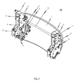
- Fig. 1 the illustrated embodiment of the solution according to the invention on a single bow door 1, which can be pivoted by means of two lateral drive units relative to a (not shown) vehicle undercarriage to release the work area of a coverable from the bow door 1 clutch.
- the lateral drive units which are used in the exemplary embodiment of the Bugklappenmoduls invention 100 and overall justify the Bugklappen kinematics, are symmetrical to each other to ensure a torque-free force curve in the drive train.
- each of the two lateral drive units has an actuating element 14, 14 'and an actuating mechanism assigned to the corresponding actuating element 14, 14'.
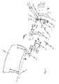
- FIG Fig. 2 referenced, in which the individual components of one of the two drive units are shown together with the bow door 1.
- each drive unit has an actuating element 14, 14 ', which in the illustrated exemplary embodiment, a pneumatically, hydraulically or electrically operating actuating cylinder 15, 15' and on actuation of the actuating element 14, 14 'from the actuating cylinder 15, 15' off or .
- retractable piston rod 16, 16 ' has.
- an actuating mechanism is provided, with which the force acting on the piston rod 16, 16' of the actuating element 14, 14 'linear force is converted into a rotational movement to pivot the bow door 1 relative to the vehicle undercarriage on a corresponding lever mechanism Apply torque.
- the pivoting mechanism has a first with the bow flap 1 releasably connected pivot lever 3 and a second with the bow flap 1 releasably connected pivot lever 3 ', wherein the first pivot lever 3 with the first actuator 14 of the first drive unit and the second pivot lever 3' cooperates with the second actuating element 14 'of the second drive unit.
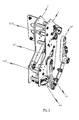
- each drive unit has an actuating mechanism which connects the corresponding actuating element 14, 14 'with the associated pivot lever 3, 3'.
- the actuating mechanism has in the exemplary embodiment, a lever 7, 7 ', on which the piston rod 16, 16' of the actuating element 14, 14 'is articulated.
- an eccentric disc 8, 8 ' is provided, which cooperates with the reversing lever 7, 7' in such a manner that upon actuation of the corresponding actuating element 14, 14 ', the torque acting on the reversing lever 7, 7' is at least partially applied to the eccentric disc 8, 8 '. is transmitted.
- the solution according to the invention is characterized not only by the fact that for pivoting the bow door 1, two separate drive units consisting of an actuating element 14, 14 'and an associated actuating mechanism for Are used, but in particular also by the fact that a synchronization element 10 is provided, with which with the aid of the individual actuating elements 14, 14 'on the associated pivot lever 3, 3' applied rotational movement can be synchronized.
- a synchronization element 10 is provided, with which with the aid of the individual actuating elements 14, 14 'on the associated pivot lever 3, 3' applied rotational movement can be synchronized.
- a rod-shaped element is used, which lies on the common axis of rotation R of the two pivot levers 3, 3 '. It is provided that the rod-shaped synchronization element 10 is connected on the one hand to the first pivot lever 3 and on the other hand to the second pivot lever 3 '.
- the respective end portions of the rod-shaped synchronization element 10 are connected to the eccentric disc 8 belonging to the first actuator 14 actuating mechanism and with the eccentric 8 'of the second actuator 14' associated actuating mechanism, so that upon actuation of at least one of the actuators 14, 14 'on the associated deflection lever 7, 7 'acting torque is transmitted to the associated eccentric disc 8, 8' and from there to the rod-shaped synchronization element 10.
- each actuating mechanism is rotatable relative to the vehicle undercarriage about an axis parallel to the rod-shaped synchronization element 10 axis of rotation, wherein the eccentric disc 8, 8' of each Actuating mechanism relative to the vehicle undercarriage about the two pivot lever 3, 3 'common rotation axis R is rotatable.
- each actuating mechanism is rotatable relative to the vehicle undercarriage about an axis parallel to the rod-shaped synchronization element 10 extending axis of rotation and has a slotted guide to forcibly guide the actuating mechanism associated eccentric 8, 8'.
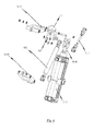
- Each actuating mechanism further comprises a connecting rod 11, 11 ', which is hinged on the one hand to the deflection lever 7, 7' of the actuating mechanism and on the other hand on the eccentric disc 8, 8 'of the actuating mechanism.
- the actuating elements 14, 14 'with the associated actuating mechanism between two firmly fixed to the vehicle underframe carrier plates 5, 5' are arranged.
- each actuating mechanism is rotatably connected to a parallel to the rod-shaped synchronization element 10 axis of rotation with a first spacer element 12, 12'.
- each actuating mechanism further comprises a compression spring 9, 9 ', in particular a gas spring, which is articulated on the one hand to the eccentric disc 8, 8' of the actuating mechanism and on the other hand to a second spacer element 13, 13 '.
- Each actuating element 14, 14 ' is rotatably connected to the two associated carrier plates 5, 5' about a rotation axis running parallel to the rod-shaped synchronization element 10.
- first and second pivot levers 3, 3 ' are each pivotally connected to the bow flap 1 about a rotation axis parallel to the rod-shaped synchronization element 10.
- a frame frame which is preferably detachably fastened to the vehicle underframe is provided, wherein the first and second actuating element 14, 14 'are connected to this frame frame.
- the invention is characterized in that for pivoting the bow door 1, two symmetrically constructed drive units are used, each of the two drive units having an actuating element 14, 14 'and an actuating mechanism to a torque on the actuation of the actuating element 14, 14' associated pivot lever 3, 3 'exercise.
- the pivoting levers 3, 3 'of the two drive units are coupled to one another via the rod-shaped synchronization element 10, so that both drive units are redundant. Even with failure of one of the two drive units, a drive unit is sufficient to fulfill the function and to enable a pivoting of the bow door 1 relative to the vehicle undercarriage. It is essential that both drive units are constructed of identical components, whereby these drive units are symmetrical and can be realized inexpensively. Due to the symmetrical design of the drive units a torque-free force curve in the drive train is guaranteed.
Landscapes
- Engineering & Computer Science (AREA)
- Mechanical Engineering (AREA)
- Life Sciences & Earth Sciences (AREA)
- Wood Science & Technology (AREA)
- Transportation (AREA)
- Actuator (AREA)
- Power-Operated Mechanisms For Wings (AREA)
- Vehicle Body Suspensions (AREA)
- Transmission Devices (AREA)
Abstract
Description
Die Erfindung betrifft eine Vorrichtung zum Verschwenken einer Bugklappe eines spurgeführten Fahrzeuges, insbesondere Schienenfahrzeuges, sowie ein Bugklappenmodul.The invention relates to a device for pivoting a nose flap of a track-guided vehicle, in particular rail vehicle, and a Bugklappenmodul.
Aus der Schienenfahrzeugtechnik ist es bekannt, die Stirnseite eines Triebzuges mit einer Bugklappe zu versehen, welche im geschlossenen Zustand den Kupplungsschacht abdecken, um Bauteile bzw. Komponenten der Kupplungsanordnung gegen Umwelteinflüsse, wie Schmutz, Eis oder Vereisung, zu schützen. Zusätzlich kann einer derartigen Bugklappe die Funktion zukommen, aerodynamisch nachteilige Frontpartien zu vermeiden, was insbesondere bei stromlinienförmigen Triebzügen, wie Hochgeschwindigkeitszügen, von Bedeutung ist.From rail vehicle technology, it is known to provide the front of a train with a bow flap, which cover the coupling shaft in the closed state to protect components or components of the clutch assembly against environmental influences, such as dirt, ice or icing. In addition, such a nose flap may have the function of avoiding aerodynamically disadvantageous front parts, which is particularly important in streamlined multiple units, such as high-speed trains, of importance.
Es sind sowohl einteilig als auch zweiteilig ausgeführte Bugklappen bekannt, welche im Normalfall geschlossen sind und nur geöffnet werden, wenn die Kupplung benutzt werden muss, etwa wenn zwei Triebzüge in Doppeltraktion verkehren. Um eine Bugklappe relativ zum Fahrzeuguntergestell verfahren und den Arbeitsbereich für eine Mittelpufferkupplung freigeben zu können, kommt eine Bugklappen-Kinematik zum Einsatz, welche manuell oder automatisch betätigbar ist.There are known both one-piece and two-piece nose flaps known which are normally closed and only open when the clutch must be used, such as when two trains drive in double traction. In order to move a nose flap relative to the vehicle undercarriage and to release the work area for a central buffer coupling, a Bugklappen kinematics is used, which can be operated manually or automatically.
Der vorliegenden Erfindung liegt die Aufgabe zugrunde, eine Bugklappen-Kinematik anzugeben, welche einen einfachen Aufbau aufweist und sich durch ihre Zuverlässigkeit auszeichnet. Insbesondere soll eine Vorrichtung zum Verschwenken einer Bugklappe eines spurgeführten Fahrzeuges sowie ein Bugklappenmodul angegeben werden, mit welchem aufgrund des einfachen Aufbaus Gewicht eingespart werden kann, während gleichzeitig die Störanfälligkeit verringert wird.The present invention has for its object to provide a nose flap kinematics, which has a simple structure and is characterized by its reliability. In particular, a device for pivoting a bow door a track-guided vehicle and a Bugklappenmodul be given, with which due to the simple structure weight can be saved, while the susceptibility is reduced.
Zur Lösung dieser Aufgabe wird eine Vorrichtung zum Verschwenken einer Bugklappe angegeben, wobei diese Vorrichtung einen ersten mit der Bugklappe verbindbaren Schwenkhebel und einen zweiten mit der Bugklappe verbindbaren Schwenkhebel aufweist, wobei zum Verschwenken der Bugklappe relativ zu dem Fahrzeuguntergestell die beiden Schwenkhebel um eine gemeinsame Rotationsachse drehbar sind. Die erfindungsgemäße Vorrichtung weist ferner ein erstes mit dem Fahrzeuguntergestell verbindbares Betätigungselement sowie ein zweites mit dem Fahrzeuguntergestell verbindbares Betätigungselement auf, wobei das erste Betätigungselement mit dem ersten Schwenkhebel derart zusammenwirkt, dass bei Betätigung des ersten Betätigungselements ein Drehmoment auf dem ersten Schwenkhebel ausgeübt wird. Das zweite Betätigungselement wirkt mit dem zweiten Schwenkhebel derart zusammen, dass bei Betätigung des zweiten Betätigungselements ein Drehmoment auf den zweiten Schwenkhebel ausgeübt wird. Erfindungsgemäß ist ferner ein Synchronisationselement in Gestalt eines auf der dem ersten und zweiten Schwenkhebel gemeinsamen Rotationsachse verlaufenden stabförmigen Elements vorgesehen, wobei das Synchronisationselement mit dem ersten Schwenkhebel einerseits und mit dem zweiten Schwenkhebel andererseits verbunden ist, um die Drehbewegung der Schwenkhebel zu synchronisieren.To solve this problem, a device is provided for pivoting a nose flap, said device having a first connectable with the nose flap pivot lever and a second connectable with the nose flap pivot lever, wherein for pivoting the nose flap relative to the vehicle underframe, the two pivot levers rotatable about a common axis of rotation are. The inventive device further comprises a first connectable to the vehicle undercarriage actuator and a second connectable to the vehicle undercarriage actuator, wherein the first actuating element cooperates with the first pivot lever such that upon actuation of the first actuating element, a torque is exerted on the first pivot lever. The second actuating element interacts with the second pivoting lever in such a way that, upon actuation of the second actuating element, a torque is exerted on the second pivoting lever. According to the invention, a synchronization element in the form of a rod-shaped element running on the first and second pivot lever is further provided, the synchronization element being connected to the first pivot lever on the one hand and to the second pivot lever on the other hand to synchronize the rotational movement of the pivot lever.
Die mit der erfindungsgemäßen Lösung erzielbaren Vorteile liegen auf der Hand. Durch das Vorsehen eines stabförmigen Synchronisationselements ist sichergestellt, dass die beiden Betätigungselemente, welche über die entsprechenden Schwenkhebel mit der Bugklappe verbunden sind, stets synchron betrieben werden. Folglich wird die zum Verschwenken der Bugklappe benötigte Kraft auf die beiden Betätigungselemente aufgeteilt. Insbesondere kann dadurch die Belastung auf die den einzelnen Betätigungselementen zugeordnete Betätigungsmechanik verringert werden, so dass die Störanfälligkeit der Bugklappen-Kinematik deutlich reduziert werden kann. Bei Ausfall eines der beiden Betätigungselemente kann die Bugklappe nach wie vor verschwenkt werden, da die Bewegung der beiden zum Verschenken der Bugklappe zum Einsatz kommenden Schwenkhebel über das stabförmige Synchronisationselement synchronisiert ist.The achievable with the inventive solution advantages are obvious. By providing a rod-shaped synchronization element ensures that the two actuators, which are connected via the corresponding pivot lever with the nose flap, are always operated synchronously. Consequently, the force required to pivot the nose flap is split between the two actuators. In particular, the load on the actuating elements assigned to the individual actuating elements can thereby be reduced, so that the susceptibility to failure of the front flap kinematics can be significantly reduced. In case of failure of one of the two actuators, the bow door can still be pivoted, since the movement of the two coming to give the nose flap for use pivot lever is synchronized via the rod-shaped synchronization element.
Vorteilhafte Weiterbildungen der erfindungsgemäßen Lösung sind in den abhängigen Patentansprüchen angegeben.Advantageous developments of the solution according to the invention are specified in the dependent claims.
In einer bevorzugten Realisierung der erfindungsgemäßen Vorrichtung sind die beiden Betätigungselemente jeweils in Gestalt eines vorzugsweise pneumatisch, hydraulisch oder elektrisch arbeitenden Betätigungszylinders ausgeführt, welcher eine aus- und einfahrbare Kolbenstange aufweist. Diese Kolbenstange wirkt vorzugsweise über eine Betätigungsmechanik mit dem zugehörigen Schwenkhebel zusammen.In a preferred embodiment of the device according to the invention, the two actuating elements are each designed in the form of a preferably pneumatically, hydraulically or electrically operating actuating cylinder, which has a retractable and retractable piston rod. This piston rod preferably cooperates via an actuating mechanism with the associated pivoting lever.
Denkbar ist es beispielsweise, dass die Betätigungsmechanik einerseits einen Umlenkhebel und andererseits eine Exzenterscheibe aufweist. Bei dieser Ausführungsform sollte an dem Umlenkhebel die Kolbenstange des zugehörigen Betätigungselements angelenkt sein. Andererseits sollte die Exzenterscheibe der Betätigungsmechanik mit einem Endbereich des stabförmigen Synchronisationselements verbunden sein. Bei dieser Realisierung der nach der erfindungsgemäßen Lösung vorgeschlagenen Bugklappen-Kinematik ist es bevorzugt, wenn der Umlenkhebel mit der Exzenterscheibe derart zusammenwirken, dass bei Betätigung des entsprechenden Betätigungselements das auf den Umlenkhebel wirkende Drehmoment zumindest teilweise auf die Exzenterscheibe und von dort auf das stabförmige Synchronisationselement übertragen wird.It is conceivable, for example, that the actuating mechanism on the one hand has a lever and on the other hand an eccentric. In this embodiment, the piston rod of the associated actuating element should be articulated on the reversing lever. On the other hand, the eccentric disc of the actuating mechanism should be connected to an end portion of the rod-shaped synchronization element. In this realization of the invention proposed by the solution Bugklappen kinematics, it is preferred if the lever interact with the eccentric disc such that upon actuation of the corresponding actuating element, the torque acting on the lever at least partially transmitted to the eccentric disc and from there to the rod-shaped synchronization element becomes.
Der Umlenkhebel der Betätigungsmechanik ist vorzugsweise einerseits vertikal zur Fahrtrichtung des Fahrzeuges verschwenkbar mit dem Fahrzeuguntergestell (Fahrzeugrahmen) und anderseits über die Exzenterscheibe mit dem Synchronisationselement verbunden. Unter dem hier verwendeten Begriff "Umlenkhebel" ist grundsätzlich eine Mechanik zu verstehen, welche ausgelegt ist, eine translatorische Bewegung in eine Rotationsbewegung der Exzenterscheibe umzusetzen.The reversing lever of the actuating mechanism is preferably on the one hand vertically to the direction of travel of the vehicle pivotally connected to the vehicle undercarriage (vehicle frame) and on the other hand connected via the eccentric disc with the synchronization element. The term "bellcrank" as used herein basically means a mechanism which is designed to convert a translational movement into a rotational movement of the eccentric disc.
Durch das Vorsehen einer einen Umlenkhebel und eine mit dem Umlenkhebel zusammenwirkenden Exzenterscheibe aufweisenden Betätigungsmechanik zum Wirkverbinden des Betätigungselements mit dem zugehörigen Schwenkhebel kann auf einfache Weise eine Rotationsbewegung herbeigeführt werden, welche wiederum zum Verschwenken der Bugklappe dient.By providing a lever and a cooperating with the bell crank eccentric having actuating mechanism for operatively connecting the actuator with the associated pivot lever can be brought about in a simple manner a rotational movement, which in turn serves to pivot the front door.
Vorzugsweise ist bei der zuletzt genannten Ausführungsform der erfindungsgemäßen Lösung der Unlenkhebel einer jeden Betätigungsmechanik relativ zum Fahrzeuguntergestell um eine parallel zum stabförmigen Synchronisationselement verlaufende Rotationsachse drehbar. Die Exzenterscheibe einer jeden Betätigungsmechanik sollte dabei vorzugsweise relativ zum Fahrzeuguntergestell um die den beiden Schwenkhebeln gemeinsame Rotationsachse drehbar sein. Hierbei handelt es sich um eine leicht zu realisierende aber dennoch störungsunanfällige Lösung für die Betätigungsmechanik, mit welcher die entsprechenden Betätigungselemente mit den zugehörigen Schwenkhebeln zusammenwirken.Preferably, in the last-mentioned embodiment of the solution according to the invention, the unlatching lever of each actuating mechanism is relative to the vehicle undercarriage about an axis of rotation extending parallel to the rod-shaped synchronization element rotatable. The eccentric disk of each actuating mechanism should preferably be rotatable relative to the vehicle undercarriage about the rotation axis common to the two pivoting levers. This is a solution that is easy to implement but nevertheless not susceptible to interference for the actuating mechanism, with which the corresponding actuating elements interact with the associated pivoting levers.
Weiter ist es denkbar, dass die Betätigungselemente jeweils relativ zum Fahrzeuguntergestell um eine parallel zum stabförmigen Synchronisationselement verlaufende Rotationsachse verschwenkbar sind, wobei der Umlenkhebel einer jeden Betätigungsmechanik relativ zum Fahrzeuguntergestell um eine parallel zum stabförmigen Synchronisationselement verlaufende Rotationsachse drehbar und eine Kulissenführung aufweisen sollte zum Zwangsführen der Exzenterscheibe der Betätigungsmechanik. Durch das Vorsehen einer derartigen Kulissenführung kann in einer leicht zu realisierenden Weise die mit dem Betätigungselement ausgeübte Linearbewegung in eine Drehbewegung umgesetzt werden, welche zum Verschwenken der Bugklappe relativ zum Fahrzeuguntergestell benötigt wird.Further, it is conceivable that the actuating elements are respectively pivotable relative to the vehicle undercarriage about an axis parallel to the rod-shaped synchronization element axis of rotation, wherein the bell crank of each actuating mechanism relative to the vehicle undercarriage should be rotatable about a parallel to the rod-shaped synchronization element rotation axis and a slotted guide for forcedly guiding the eccentric the actuating mechanism. By providing such a slotted guide, the linear movement exerted with the actuating element linear movement can be converted into a rotational movement, which is needed for pivoting the nose flap relative to the vehicle undercarriage in an easy to implement manner.
In einer bevorzugten Realisierung der Betätigungsmechanik ist vorgesehen, dass diese eine Verbindungsstange aufweist, welche einerseits an dem Umlenkhebel der Betätigungsmechanik und andererseits an der Exzenterscheibe der Betätigungsmechanik angelenkt ist.In a preferred embodiment of the actuating mechanism is provided that it has a connecting rod which is articulated on the one hand to the reversing lever of the actuating mechanism and on the other hand on the eccentric disc of the actuating mechanism.
Vorzugsweise ist jedes Betätigungselemente mit der zugehörigen Betätigungsmechanik zwischen zwei mit dem Fahrzeuguntergestell fest verbindbaren Trägerplatten angeordnet, um die empfindlichen Baugruppen der Bugklappen-Kinematik zu schützen. Denkbar ist hierbei, dass die Trägerplatten jeweils in einer Ebene senkrecht zur Ausrichtung des stabförmigen Synchronisationselements liegen und über mindestens ein Abstandselement fest miteinander verbunden sind.Preferably, each actuator is arranged with the associated actuating mechanism between two firmly connectable to the vehicle underframe carrier plates to protect the sensitive assemblies of the front door kinematics. It is conceivable here that the carrier plates are each in a plane perpendicular to the orientation of the rod-shaped synchronization element and are firmly connected to each other via at least one spacer element.
Ferner ist es denkbar und bevorzugt, dass mindestens zwei Abstandselemente zum Verbinden der Trägerplatten zum Einsatz kommen, und dass der Umlenkhebel einer jeden Betätigungsmechanik um eine parallel zum stabförmigen Synchronisationselement verlaufende Rotationsachse drehbar mit einem ersten der mindestens zwei Abstandselemente verbunden ist. Zusätzlich hierzu kann ferner jede Betätigungsmechanik eine Druckfeder, insbesondere Gasdruckfeder, aufweisen, welche einerseits an der Exzenterscheibe der Betätigungsmechanik und andererseits an einem zweiten der mindestens zwei Abstandselemente angelenkt ist.Furthermore, it is conceivable and preferred that at least two spacer elements are used for connecting the carrier plates, and that the deflection lever of each actuating mechanism is rotatably connected to a first of the at least two spacer elements about an axis of rotation extending parallel to the rod-shaped synchronization element. In addition to this, furthermore, each actuating mechanism may comprise a compression spring, in particular a gas pressure spring, which on the one hand on the Eccentric disc of the actuating mechanism and on the other hand hinged to a second of the at least two spacer elements.
Um die Relativbewegung des mit einem zwischen den Trägerplatten angeordneten Betätigungselement betätigbaren Schwenkhebels begrenzen zu können, ist es bevorzugt, wenn an mindestens einer der beiden Trägerplatten ein Anschlag vorgesehen ist.In order to be able to limit the relative movement of the pivot lever which can be actuated with an actuating element arranged between the carrier plates, it is preferred if a stop is provided on at least one of the two carrier plates.
Im Hinblick auf die Anlenkung der Bugklappe ist in einer bevorzugten Realisierung der erfindungsgemäßen Vorrichtung vorgesehen, dass der erste und zweite Schwenkhebel jeweils um eine parallel zum stabförmigen Synchronisationselement verlaufende Rotationsachse mit der Bugklappe verschwenkbar verbunden sind. Ferner sollte mindestens ein erster und ein zweiter Zusatz-Schwenkhebel vorgesehen sein, welche mit dem ersten und zweiten Schwenkhebel derart zusammenwirken, dass der erste Schwenkhebel mit dem ersten Zusatz-Schwenkhebel und der zweite Schwenkhebel mit dem zweiten Zusatz-Schwenkhebel jeweils ein Vier-Gelenk ausbilden, über welches die Bugklappe mit dem Fahrzeuguntergestell verbindbar ist. Hierdurch ist es möglich, dass zum Verschwenken der Bugklappe diese eine Bewegung relativ zum Fahrzeuguntergestell ausführt, welche eine Superposition einer Linear- und einer Schwenkbewegung ist, so dass der zum verschwenken der Bugklappe zu Verfügung zu stellende Freiraum verringert werden kann.With regard to the articulation of the nose flap is provided in a preferred realization of the device according to the invention, that the first and second pivot levers are pivotally connected in each case about an axis parallel to the rod-shaped synchronization element axis of rotation with the nose flap. Further, at least a first and a second additional pivot lever should be provided, which cooperate with the first and second pivot lever such that the first pivot lever with the first additional pivot lever and the second pivot lever with the second additional pivot lever each form a four-joint , via which the nose flap can be connected to the vehicle undercarriage. This makes it possible that for pivoting the nose flap this performs a movement relative to the vehicle undercarriage, which is a superposition of a linear and a pivoting movement, so that the pivoting of the nose flap available to be set free space can be reduced.
Schließlich ist in einer bevorzugten Ausführungsform der erfindungsgemäßen Vorrichtung vorgesehen, dass ein mit dem Fahrzeuguntergestell vorzugsweise lösbar befestigbares Rahmengestell vorgesehen ist, über welches das erste und das zweite Betätigungselement mit dem Fahrzeuguntergestell (indirekt) verbunden sind.Finally, in a preferred embodiment of the device according to the invention, provision is made for a frame frame, which is preferably detachably fastened to the vehicle underframe, via which the first and the second actuating element are connected (indirectly) to the vehicle undercarriage.
Die Erfindung betrifft ferner ein Bugklappenmodul für ein spurgeführtes Fahrzeug, insbesondere Schienenfahrzeug, wobei das Bugklappenmodul eine vorzugsweise aus einem glasfaserverstärktem Kunststoff gefertigte Bugklappe sowie eine Bugklappen-Kinematik mit einer Vorrichtung der zuvor beschriebenen Art zum Verschwenken der Bugklappe aufweist.The invention further relates to a bulkhead module for a track-guided vehicle, in particular rail vehicle, wherein the Bugklappenmodul has a preferably made of a fiberglass reinforced plastic nose flap and a Bugklappen kinematics with a device of the type described above for pivoting the nose flap.
Im Folgenden wird ein Ausführungsbeispiel der Erfindung anhand der beiliegenden Zeichnungen näher beschrieben.In the following an embodiment of the invention will be described in more detail with reference to the accompanying drawings.
Es zeigen:
- Fig. 1
- eine perspektivische Ansicht auf eine exemplarische Ausführungsform eines Bugklappenmoduls gemäß der vorliegenden Erfindung;
- Fig. 2
- eine Explosionsdarstellung von einem Teil der bei dem Bugklappenmodul gemäß
Fig. 1 zum Einsatz kommenden Bauteile; - Fig. 3
- eine perspektivische Ansicht auf eine Betätigungsmechanik mit zugehörigem Betätigungselement des Bugklappenmoduls gemäß
Fig. 1 ; - Fig. 4
- eine Explosionsdarstellung von Teilen der Betätigungsmechanik gemäß
Fig. 3 ; - Fig. 5a
- eine Seitenansicht des Bugklappenmoduls gemäß
Fig. 1 im geschlossenen Zustand der Bugklappe; - Fig. 5b
- eine Seitenansicht des Bugklappenmoduls gemäß
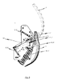
Fig. 1 in einem geöffneten Zustand der Bugklappe; und - Fig. 6
- eine teilgeschnittene Seitenansicht des Bugklappenmoduls gemäß
Fig. 1 in einem geöffneten bzw. geschlossenen Zustand der Bugklappe.
- Fig. 1
- a perspective view of an exemplary embodiment of a Bugklappenmoduls according to the present invention;
- Fig. 2
- an exploded view of a part of the Bugklappenmodul according to
Fig. 1 used components; - Fig. 3
- a perspective view of an actuating mechanism with associated actuator of the Bugklappenmoduls according to
Fig. 1 ; - Fig. 4
- an exploded view of parts of the actuating mechanism according to
Fig. 3 ; - Fig. 5a
- a side view of the Bugklappenmoduls according to
Fig. 1 in the closed state of the nose flap; - Fig. 5b
- a side view of the Bugklappenmoduls according to
Fig. 1 in an open state of the nose flap; and - Fig. 6
- a partially sectioned side view of the Bugklappenmoduls according to
Fig. 1 in an open or closed state of the bow door.
Nachfolgend wird unter Bezugnahme auf die beiliegenden Zeichnungen ein exemplarisches Ausführungsbeispiel eines Bugklappenmoduls 100 beschrieben, bei welchem zum Verschwenken einer Bugklappe 1 eine Vorrichtung (Bugklappen-Kinematik) gemäß der vorliegenden Erfindung zum Einsatz kommt.Hereinafter, an exemplary embodiment of a
Im Einzelnen, und wie es insbesondere der Darstellung in
Im Einzelnen weist jede der beiden seitlichen Antriebseinheiten ein Betätigungselement 14, 14' sowie eine dem entsprechenden Betätigungselement 14, 14' zugeordnete Betätigungsmechanik auf. In diesem Zusammenhang wird auf die Explosionsdarstellung gemäß
Demgemäß weist jede Antriebseinheit ein Betätigungselement 14, 14' auf, welches bei der dargestellten exemplarischen Ausführungsform einen pneumatisch, hydraulisch oder elektrisch arbeitenden Betätigungszylinder 15, 15' und eine bei Betätigung des Betätigungselements 14, 14' aus dem Betätigungszylinder 15, 15' aus- bzw. einfahrbare Kolbenstange 16, 16' aufweist. Für jedes Betätigungselement 14, 14' ist eine Betätigungsmechanik vorgesehen, mit welcher die auf die Kolbenstange 16, 16' des Betätigungselements 14, 14' ausgeübte Linearkraft in eine Drehbewegung umgesetzt wird, um zum Verschwenken der Bugklappe 1 relativ zum Fahrzeuguntergestell auf einen entsprechenden Hebelmechanismus ein Drehmoment auszuüben.Accordingly, each drive unit has an actuating element 14, 14 ', which in the illustrated exemplary embodiment, a pneumatically, hydraulically or electrically operating actuating cylinder 15, 15' and on actuation of the actuating element 14, 14 'from the actuating cylinder 15, 15' off or . retractable piston rod 16, 16 'has. For each actuating element 14, 14 ', an actuating mechanism is provided, with which the force acting on the piston rod 16, 16' of the actuating element 14, 14 'linear force is converted into a rotational movement to pivot the
Im Einzelnen und wie es insbesondere der Darstellung in
Wie es insbesondere der
Die erfindungsgemäße Lösung zeichnet sich nicht nur dadurch aus, dass zum Verschwenken der Bugklappe 1 zwei separate Antriebseinheiten bestehend aus jeweils einem Betätigungselement 14, 14' und einer zugehörigen Betätigungsmechanik zum Einsatz kommen, sondern insbesondere auch dadurch aus, dass ein Synchronisationselement 10 vorgesehen ist, mit welchem die mit Hilfe der einzelnen Betätigungselemente 14, 14' auf die zugehörigen Schwenkhebel 3, 3' ausgeübte Drehbewegung synchronisiert werden kann. Im Einzelnen, und wie es insbesondere der Darstellung in
Die jeweiligen Endbereiche des stabförmigen Synchronisationselements 10 sind mit der Exzenterscheibe 8 der zum ersten Betätigungselement 14 gehörenden Betätigungsmechanik sowie mit der Exzenterscheibe 8' der zum zweiten Betätigungselement 14' gehörenden Betätigungsmechanik verbunden, so dass bei Betätigung von zumindest einem der Betätigungselemente 14, 14' das auf den zugehörigen Umlenkhebel 7, 7' wirkende Drehmoment auf die zugehörige Exzenterscheibe 8, 8' und von dort auf das stabförmige Synchronisationselement 10 übertragen wird.The respective end portions of the rod-shaped
Wie es insbesondere aus einer Zusammenschau der
Anhand beispielsweise der Darstellung in
Wie dargestellt, ist der Umlenkhebel 7, 7' einer jeden Betätigungsmechanik relativ zum Fahrzeuguntergestell um eine parallel zum stabförmigen Synchronisationselement 10 verlaufende Rotationsachse drehbar und weist eine Kulissenführung auf, um die der Betätigungsmechanik zugehörige Exzenterscheibe 8, 8' zwangszuführen. Jede Betätigungsmechanik weist ferner eine Verbindungsstange 11, 11' auf, welche einerseits an dem Umlenkhebel 7, 7' der Betätigungsmechanik und andererseits an der Exzenterscheibe 8, 8' der Betätigungsmechanik angelenkt ist.As shown, the reversing lever 7, 7 'of each actuating mechanism is rotatable relative to the vehicle undercarriage about an axis parallel to the rod-shaped
Bei der exemplarischen Ausführungsform der erfindungsgemäßen Bugklappen-Kinematik sind die Betätigungselemente 14, 14' mit der zugehörigen Betätigungsmechanik zwischen zwei mit dem Fahrzeuguntergestell fest verbindbaren Trägerplatten 5, 5' angeordnet. Im Einzelnen liegen bei der dargestellten Ausführungsform die Trägerplatten 5, 5' jeweils in einer Ebene senkrecht zur Ausrichtung des stabförmigen Synchronisationselements 10 und sind über zwei Abstandselemente 12, 13; 12', 13' fest miteinander verbunden. Durch das Vorsehen von derartigen Trägerplatten 5, 5' können die Betätigungselemente 14, 14' sowie die zugehörige Betätigungsmechanik in einer leicht zu realisierenden aber dennoch effektiven Weise vor Beschädigungen geschützt werden.In the exemplary embodiment of the Bugklappen kinematics invention, the actuating elements 14, 14 'with the associated actuating mechanism between two firmly fixed to the vehicle
Wie es insbesondere der
Der Darstellung in
Bei der in den Zeichnungen dargestellten exemplarischen Ausführungsform sind der erste und der zweite Schwenkhebel 3, 3' jeweils um eine parallel zum stabförmigen Synchronisationselement 10 verlaufende Rotationsachse verschwenkbar mit der Bugklappe 1 verbunden. Ferner sind ein erster und ein zweiter Zusatz-Schwenkhebel 4, 4' vorgesehen, welche mit dem ersten und zweiten Schwenkhebel 3, 3' derart zusammenwirken, dass der erste Schwenkhebel 3 mit dem ersten Zusatz-Schwenkhebel 4 und der zweite Schwenkhebel 3' mit dem zweiten Zusatz-Schwenkhebel 4' jeweils ein Vier-Gelenk ausbilden, über welches die Bugklappe 1 mit dem Fahrzeuguntergestell verbunden ist.In the exemplary embodiment illustrated in the drawings, the first and second pivot levers 3, 3 'are each pivotally connected to the
Die erfindungsgemäße Lösung ist nicht auf das in den Zeichnungen dargestellte exemplarische Ausführungsbeispiel beschränkt, sondern ergibt sich aus einer Zusammenschau sämtlicher hierin offenbarter Merkmale.The solution according to the invention is not limited to the exemplary embodiment shown in the drawings, but results from a synopsis of all features disclosed herein.
Insbesondere ist es denkbar, dass ferner ein mit dem Fahrzeuguntergestell vorzugsweise lösbar befestigtes Rahmengestell vorgesehen ist, wobei das erste und zweite Betätigungselement 14, 14' mit diesem Rahmengestell verbunden sind.In particular, it is conceivable that, furthermore, a frame frame which is preferably detachably fastened to the vehicle underframe is provided, wherein the first and second actuating element 14, 14 'are connected to this frame frame.
Die Erfindung zeichnet sich dadurch aus, dass zum Verschwenken der Bugklappe 1 zwei symmetrisch aufgebaute Antriebseinheiten zum Einsatz kommen, wobei jede der beiden Antriebseinheiten ein Betätigungselement 14, 14' und eine Betätigungsmechanik aufweist, um bei Betätigung des Betätigungselements 14, 14' ein Drehmoment auf den zugeordneten Schwenkhebel 3, 3' auszuüben. Die Schwenkhebel 3, 3' der beiden Antriebseinheiten sind über das stabförmige Synchronisationselement 10 miteinander gekoppelt, so dass beide Antriebseinheiten redundant sind. Auch bei Ausfall einer der beiden Antriebseinheiten reicht eine Antriebseinheit aus, um die Funktion zu erfüllen und ein Verschwenken der Bugklappe 1 relativ zum Fahrzeuguntergestell zu ermöglichen. Wesentlich ist, dass beide Antriebseinheiten aus identischen Komponenten aufgebaut sind, wodurch diese Antriebseinheiten symmetrisch sind und kostengünstig realisiert werden können. Durch den symmetrischen Aufbau der Antriebseinheiten ist ein momentenfreier Kraftverlauf im Antriebsstrang gewährleistet.The invention is characterized in that for pivoting the
- 11
- BugklappeBugklappe
- 3, 3'3, 3 '
- erster/zweiter Schwenkhebelfirst / second pivot lever
- 4, 4'4, 4 '
- erster/zweiter Zusatz-Schwenkhebelfirst / second additional swivel lever
- 5, 5'5, 5 '
- Trägerplattesupport plate
- 6, 6'6, 6 '
- Anschlagattack
- 7, 7'7, 7 '
- UmlenkhebelUmlenkhebel
- 8, 8'8, 8 '
- Exzenterscheibeeccentric
- 9, 9'9, 9 '
- Druckfeder/GlasdruckfederSpring / glass pressure spring
- 1010
- stabförmiges Synchronisationselementrod-shaped synchronization element
- 11, 11'11, 11 '
- Verbindungsstangeconnecting rod
- 12, 12'12, 12 '
- erstes Abstandselementfirst spacer element
- 13, 13'13, 13 '
- zweites Abstandselementsecond spacer element
- 14, 14'14, 14 '
- erstes/zweites Betätigungselementfirst / second actuator
- 15, 15'15, 15 '
- Betätigungszylinder des ersten/zweiten BetätigungselementsActuating cylinder of the first / second actuator
- 16, 16'16, 16 '
- Kolbenstange des ersten/zweiten BetätigungselementsPiston rod of the first / second actuator
- 100100
- BugklappenmodulBugklappenmodul
- RR
- Gemeinsame Rotationsachse des ersten und zweiten SchwenkhebelsCommon axis of rotation of the first and second pivot lever
Claims (15)
wobei die Betätigungselemente (14, 14') jeweils einen vorzugsweise pneumatisch, hydraulisch oder elektrisch arbeitenden Betätigungszylinder (15, 15') mit einer aus- und einfahrbaren Kolbenstange (16, 16') aufweisen.Device according to claim 1,
wherein the actuating elements (14, 14 ') each have a preferably pneumatically, hydraulically or electrically operating actuating cylinder (15, 15') with a retractable and retractable piston rod (16, 16 ').
wobei die Betätigungselemente (14, 14') jeweils über eine Betätigungsmechanik mit dem zugehörigen Schwenkhebel (3, 3') zusammenwirken, wobei die Betätigungsmechanik folgendes aufweist:
wherein the actuating elements (14, 14 ') cooperate in each case via an actuating mechanism with the associated pivoting lever (3, 3'), wherein the actuating mechanism has the following:
wobei der Umlenkhebel (7, 7') einer jeden Betätigungsmechanik relativ zum Fahrzeuguntergestell um eine parallel zum stabförmigen Synchronisationselement (10) verlaufende Rotationsachse drehbar ist; und
wobei die Exzenterscheibe (8, 8') einer jeden Betätigungsmechanik relativ zum Fahrzeuguntergestell um die den beiden Schwenkhebeln (3, 3') gemeinsame Rotationsachse (R) drehbar ist.Device according to claim 3,
wherein the deflection lever (7, 7 ') of each actuating mechanism is rotatable relative to the vehicle undercarriage about an axis of rotation parallel to the rod-shaped synchronization element (10); and
wherein the eccentric disc (8, 8 ') of each actuating mechanism relative to the vehicle undercarriage about the two pivot levers (3, 3') common rotation axis (R) is rotatable.
wobei die Betätigungselemente (14, 14') jeweils relativ zum Fahrzeuguntergestell um eine parallel zum stabförmigen Synchronisationselement (10) verlaufende Rotationsachse verschwenkbar sind, und
wobei der Umlenkhebel (7, 7') einer jeden Betätigungsmechanik relativ zum Fahrzeuguntergestell um eine parallel zum stabförmigen Synchronisationselement (10) verlaufende Rotationsachse drehbar ist und eine Kulissenführung aufweist zum Zwangsführen der Exzenterscheibe (8, 8') der Betätigungsmechanik.Apparatus according to claim 3 or 4,
wherein the actuating elements (14, 14 ') in each case relative to the vehicle undercarriage about an axis parallel to the rod-shaped synchronization element (10) extending axis of rotation are pivotable, and
wherein the deflection lever (7, 7 ') of each actuating mechanism is rotatable relative to the vehicle undercarriage about an axis parallel to the rod-shaped synchronization element (10) extending axis of rotation and has a slotted guide for forcedly guiding the eccentric disc (8, 8') of the actuating mechanism.
wobei ferner jede Betätigungsmechanik eine Verbindungsstange (11, 11') aufweist, welche einerseits an dem Umlenkhebel (7, 7') der Betätigungsmechanik und andererseits an der Exzenterscheibe (8, 8') der Betätigungsmechanik angelenkt ist.Device according to one of claims 3 to 5,
wherein furthermore each actuating mechanism has a connecting rod (11, 11 ') which is articulated on the one hand to the deflection lever (7, 7') of the actuating mechanism and on the other hand to the eccentric disc (8, 8 ') of the actuating mechanism.
wobei jedes Betätigungselement (14, 14') mit der zugehörigen Betätigungsmechanik zwischen zwei mit dem Fahrzeuguntergestell fest verbindbaren Trägerplatten (5, 5') angeordnet ist.Device according to one of claims 3 to 6,
wherein each actuating element (14, 14 ') with the associated actuating mechanism between two with the vehicle underframe firmly connectable support plates (5, 5') is arranged.
wobei jedes Betätigungselement (14, 14') um eine parallel zum stabförmigen Synchronisationselement (10) verlaufende Rotationsachse drehbar mit den beiden zugehörigen Trägerplatten (5, 5') verbunden ist.Device according to claim 7,
wherein each actuating element (14, 14 ') is rotatably connected to the two associated carrier plates (5, 5') about a rotation axis extending parallel to the rod-shaped synchronization element (10).
wobei die Trägerplatten (5, 5') jeweils in einer Ebene senkrecht zur Ausrichtung des stabförmigen Synchronisationselements (10) liegen und über mindestens ein Abstandselement (12, 13; 12', 13') fest miteinander verbunden sind.Device according to claim 7 or 8,
wherein the carrier plates (5, 5 ') each lie in a plane perpendicular to the orientation of the rod-shaped synchronization element (10) and are fixedly connected to one another via at least one spacer element (12, 13; 12', 13 ').
der Umlenkhebel (7, 7') einer jeden Betätigungsmechanik um eine parallel zum stabförmigen Synchronisationselement (10) verlaufende Rotationsachse drehbar mit einem ersten Abstandselement (12, 12') verbunden ist.Device according to claim 9,
the deflection lever (7, 7 ') of each actuating mechanism is rotatably connected to a first spacer element (12, 12') about a rotation axis extending parallel to the rod-shaped synchronization element (10).
wobei ferner jede Betätigungsmechanik eine Druckfeder (9, 9'), insbesondere Gasdruckfeder, aufweist, welche einerseits an der Exzenterscheibe (8, 8') der Betätigungsmechanik und andererseits an einem zweiten Abstandselement (13, 13') angelenkt ist.Device according to claim 9 or 10,
wherein each actuating mechanism further comprises a compression spring (9, 9 '), in particular gas spring, which is hinged on the one hand to the eccentric disc (8, 8') of the actuating mechanism and on the other hand to a second spacer element (13, 13 ').
wobei an mindestens einer der beiden Trägerplatten (5, 5') ein Anschlag (6, 6') vorgesehen ist zum Begrenzen der Relativbewegung des mit dem zwischen den Trägerplatten (5, 5') angeordneten Betätigungselement (14, 14') betätigbaren Schwenkhebels (3, 3').Device according to one of claims 7 to 11,
wherein on at least one of the two support plates (5, 5 ') a stop (6, 6') is provided for limiting the relative movement of the with between the Support plates (5, 5 ') arranged actuating element (14, 14') operable pivot lever (3, 3 ').
wobei der erste und zweite Schwenkhebel (3, 3') jeweils um eine parallel zum stabförmigen Synchronisationselement (10) verlaufende Rotationsachse verschwenkbar mit der Bugklappe (1) verbindbar sind, und
wobei ferner ein erster und ein zweiter Zusatz-Schwenkhebel (4, 4') vorgesehen sind, welche mit dem ersten und zweiten Schwenkhebel (3, 3') derart zusammenwirken, dass der erste Schwenkhebel (3) mit dem ersten Zusatz-Schwenkhebel (4) und der zweite Schwenkhebel (3') mit dem zweiten Zusatz-Schwenkhebel (4') jeweils ein Vier-Gelenk ausbilden, über welches die Bugklappe (1) mit dem Fahrzeuguntergestell verbindbar ist.Device according to one of the preceding claims,
wherein the first and second pivot levers (3, 3 ') in each case about a parallel to the rod-shaped synchronization element (10) extending axis of rotation are pivotally connected to the nose flap (1), and
further comprising first and second auxiliary pivoting levers (4, 4 ') cooperating with the first and second pivoting levers (3, 3') such that the first pivoting lever (3) engages with the first auxiliary pivoting lever (4 ) and the second pivot lever (3 ') with the second additional pivot lever (4') each form a four-joint, via which the nose flap (1) with the vehicle undercarriage is connectable.
welche ferner ein mit dem Fahrzeuguntergestell vorzugsweise lösbar befestigbares Rahmengestell aufweist, wobei das erste und zweite Betätigungselement (14, 14') mit dem Rahmengestell verbunden sind.Device according to one of the preceding claims,
which further comprises a vehicle frame preferably releasably attachable frame, wherein the first and second actuating element (14, 14 ') are connected to the frame.
Priority Applications (7)
| Application Number | Priority Date | Filing Date | Title |
|---|---|---|---|
| EP10165279.0A EP2394879B1 (en) | 2010-06-08 | 2010-06-08 | Device for moving a bow ramp and bow ramp module |
| AU2011202010A AU2011202010B2 (en) | 2010-06-08 | 2011-05-02 | Device for pivoting a front hatch as well as a front hatch module |
| KR1020110047330A KR101290452B1 (en) | 2010-06-08 | 2011-05-19 | Device for pivoting a front hatch as well as a front hatch module |
| CN201110136540.9A CN102310865B (en) | 2010-06-08 | 2011-05-24 | Device for pivoting a front hatch as well as a front hatch module |
| JP2011125120A JP2011255886A (en) | 2010-06-08 | 2011-06-03 | Rotating apparatus for front hatch and front hatch module |
| RU2011122905/11A RU2011122905A (en) | 2010-06-08 | 2011-06-06 | DEVICE FOR TURNING THE WINDSHIELD, AND ALSO THE NODE OF THE WINDSHIELD |
| US13/155,886 US8468953B2 (en) | 2010-06-08 | 2011-06-08 | Device for pivoting a front hatch as well as a front hatch module |
Applications Claiming Priority (1)
| Application Number | Priority Date | Filing Date | Title |
|---|---|---|---|
| EP10165279.0A EP2394879B1 (en) | 2010-06-08 | 2010-06-08 | Device for moving a bow ramp and bow ramp module |
Publications (2)
| Publication Number | Publication Date |
|---|---|
| EP2394879A1 true EP2394879A1 (en) | 2011-12-14 |
| EP2394879B1 EP2394879B1 (en) | 2016-12-14 |
Family
ID=43034561
Family Applications (1)
| Application Number | Title | Priority Date | Filing Date |
|---|---|---|---|
| EP10165279.0A Active EP2394879B1 (en) | 2010-06-08 | 2010-06-08 | Device for moving a bow ramp and bow ramp module |
Country Status (7)
| Country | Link |
|---|---|
| US (1) | US8468953B2 (en) |
| EP (1) | EP2394879B1 (en) |
| JP (1) | JP2011255886A (en) |
| KR (1) | KR101290452B1 (en) |
| CN (1) | CN102310865B (en) |
| AU (1) | AU2011202010B2 (en) |
| RU (1) | RU2011122905A (en) |
Cited By (4)
| Publication number | Priority date | Publication date | Assignee | Title |
|---|---|---|---|---|
| WO2013024142A1 (en) * | 2011-08-17 | 2013-02-21 | Voith Patent Gmbh | Device for pivoting one or more front flaps of a track-guided vehicle |
| EP2949538A1 (en) * | 2014-05-30 | 2015-12-02 | Dellner Couplers AB | Mounting for a front hatch of a car of a train and car of a train |
| WO2016174070A1 (en) * | 2015-04-27 | 2016-11-03 | Voith Patent Gmbh | Device for moving one or more front flaps |
| WO2020094426A1 (en) * | 2018-11-06 | 2020-05-14 | Voith Patent Gmbh | Front flap assembly |
Families Citing this family (12)
| Publication number | Priority date | Publication date | Assignee | Title |
|---|---|---|---|---|
| DE102009041445A1 (en) * | 2009-09-16 | 2011-03-24 | Siemens Aktiengesellschaft | Rail vehicle with front coupling panel |
| DE102010023318A1 (en) * | 2010-06-10 | 2011-12-15 | Voith Patent Gmbh | Device for pivoting one or more nose flaps of a track-guided vehicle and Bugklappenmodul |
| EP2644495B1 (en) * | 2012-03-27 | 2015-06-17 | AIRBUS HELICOPTERS DEUTSCHLAND GmbH | Emergency opening system for an aircraft cabin door |
| CN103883195B (en) * | 2012-12-20 | 2016-02-03 | 南车青岛四方机车车辆股份有限公司 | Rail vehicle switching mechanism for front cover and method for designing |
| US10655381B2 (en) * | 2013-10-18 | 2020-05-19 | Crrc Qingdao Sifang Rolling Stock Research Institute Co., Ltd. | Locking device and opening and closing mechanism having the same |
| CN103510783B (en) * | 2013-10-18 | 2015-09-30 | 青岛四方车辆研究所有限公司 | With the switching mechanism of self-locking device |
| US11697962B2 (en) | 2013-10-18 | 2023-07-11 | Crrc Qingdao Sifang Rolling Stock Research Institute Co., Ltd. | Opening and closing mechanism and train having the same |
| CN105109503B (en) * | 2015-09-09 | 2018-04-06 | 中车青岛四方机车车辆股份有限公司 | A kind of rail vehicle and its hood opening-closing mechanism |
| EP3168138B1 (en) * | 2015-11-10 | 2018-06-06 | Airbus Operations GmbH | Aircraft door assembly |
| CN108128317A (en) * | 2018-01-08 | 2018-06-08 | 株洲九方装备股份有限公司 | A kind of switching mechanism rotating opening device and rotating opening method |
| PL3929056T3 (en) * | 2020-06-26 | 2023-04-24 | Dellner Couplers Ab | System of a side skirt for a car of a multi-car vehicle and a side skirt support |
| KR102576185B1 (en) * | 2023-03-14 | 2023-09-07 | 엑스티지(주) | Front hatch door installing structure |
Citations (5)
| Publication number | Priority date | Publication date | Assignee | Title |
|---|---|---|---|---|
| DE29706073U1 (en) * | 1997-04-07 | 1997-07-31 | Deutsche Waggonbau AG, 12526 Berlin | Device for operating the bow flaps of railcars or control cars |
| EP0811539A2 (en) * | 1996-06-05 | 1997-12-10 | BREDA COSTRUZIONI FERROVIARIE S.p.A. | Front structure of a railway electric locomotive with a retractable door for the access to the automatic coupler |
| DE19921927A1 (en) * | 1998-07-16 | 2000-01-27 | Siemens Duewag Gmbh | Front end assembly for city train, tram or bus incorporates hinged or tilting front bonnet section under front window |
| WO2007073273A1 (en) * | 2005-12-23 | 2007-06-28 | Dellner Couplers Ab | Front hatch having cantilever hatch-operating mechanism |
| EP1857340A2 (en) * | 2006-05-18 | 2007-11-21 | Siemens Aktiengesellschaft | Mass transit vehicles, in particular an urban railcar, with a front bonnet |
Family Cites Families (20)
| Publication number | Priority date | Publication date | Assignee | Title |
|---|---|---|---|---|
| US3333362A (en) * | 1965-02-05 | 1967-08-01 | Ford Motor Co | Convertible backlight |
| DE2352179A1 (en) | 1973-10-17 | 1975-04-30 | Daimler Benz Ag | IMPACT PROTECTION DEVICE FOR A MOTOR VEHICLE |
| US4051746A (en) * | 1976-02-20 | 1977-10-04 | Rolf Sven Gunnar Liljeros | Mechanism for opening and closing a movable member |
| US4510714A (en) * | 1982-09-30 | 1985-04-16 | The Boeing Company | Powered outward-opening cargo door |
| US4497462A (en) * | 1983-03-28 | 1985-02-05 | The Boeing Company | Outward opening electrically powered plug-type cargo door |
| FR2633580B1 (en) * | 1988-07-01 | 1991-02-15 | Alsthom | DEVICE FOR OPENING AND CLOSING A VEHICLE BODY SKIRT |
| JPH0751969Y2 (en) * | 1991-01-25 | 1995-11-29 | 川重鉄道車両エンジニアリング株式会社 | Cover opener |
| US5275303A (en) * | 1992-02-03 | 1994-01-04 | Applied Materials, Inc. | Valve closure mechanism for semiconductor deposition apparatus |
| JPH06305332A (en) * | 1993-04-27 | 1994-11-01 | Kuroishi Tekko Kk | Door device for vehicle |
| DE19635382A1 (en) * | 1996-08-31 | 1998-03-05 | Linke Hofmann Busch | Horizontally pivotable cover for a passage opening in an end face of a rail vehicle for a central buffer coupling |
| JP2942218B2 (en) * | 1997-06-30 | 1999-08-30 | 川崎重工業株式会社 | Coupling cover of high-speed leading vehicle |
| JP3078797B1 (en) * | 1999-06-04 | 2000-08-21 | 川崎重工業株式会社 | Switchgear for coupler cover |
| EP1154109B1 (en) * | 2000-05-12 | 2009-01-07 | Antonio Giovannetti | A spring operated device for door movement, having an adjustable lever arm of the spring |
| US6386613B1 (en) * | 2000-09-26 | 2002-05-14 | Unicell Limited | Truck rear door opening mechanism |
| JP3664438B2 (en) * | 2002-02-27 | 2005-06-29 | タキゲン製造株式会社 | Opening and closing support device for trunk lids such as buses |
| DE10320098B4 (en) * | 2003-05-05 | 2010-10-14 | Stabilus Gmbh | Damper actuator for a flap |
| JP2005145268A (en) * | 2003-11-17 | 2005-06-09 | Odakyu Dentetsu Kk | Opening/closing support device for underfloor cover for railway vehicle |
| US7293819B2 (en) * | 2006-04-03 | 2007-11-13 | M&C Corporation | Decklid hinge with motor to automate opening and closing |
| KR100830570B1 (en) | 2007-12-07 | 2008-05-22 | (주)동우자동도어 | Apparatus for opening and closing drive part cover in psd |
| JP2009227055A (en) * | 2008-03-21 | 2009-10-08 | Nippon Sharyo Seizo Kaisha Ltd | Railroad vehicle |
-
2010
- 2010-06-08 EP EP10165279.0A patent/EP2394879B1/en active Active
-
2011
- 2011-05-02 AU AU2011202010A patent/AU2011202010B2/en not_active Ceased
- 2011-05-19 KR KR1020110047330A patent/KR101290452B1/en active IP Right Grant
- 2011-05-24 CN CN201110136540.9A patent/CN102310865B/en active Active
- 2011-06-03 JP JP2011125120A patent/JP2011255886A/en not_active Ceased
- 2011-06-06 RU RU2011122905/11A patent/RU2011122905A/en not_active Application Discontinuation
- 2011-06-08 US US13/155,886 patent/US8468953B2/en not_active Expired - Fee Related
Patent Citations (5)
| Publication number | Priority date | Publication date | Assignee | Title |
|---|---|---|---|---|
| EP0811539A2 (en) * | 1996-06-05 | 1997-12-10 | BREDA COSTRUZIONI FERROVIARIE S.p.A. | Front structure of a railway electric locomotive with a retractable door for the access to the automatic coupler |
| DE29706073U1 (en) * | 1997-04-07 | 1997-07-31 | Deutsche Waggonbau AG, 12526 Berlin | Device for operating the bow flaps of railcars or control cars |
| DE19921927A1 (en) * | 1998-07-16 | 2000-01-27 | Siemens Duewag Gmbh | Front end assembly for city train, tram or bus incorporates hinged or tilting front bonnet section under front window |
| WO2007073273A1 (en) * | 2005-12-23 | 2007-06-28 | Dellner Couplers Ab | Front hatch having cantilever hatch-operating mechanism |
| EP1857340A2 (en) * | 2006-05-18 | 2007-11-21 | Siemens Aktiengesellschaft | Mass transit vehicles, in particular an urban railcar, with a front bonnet |
Cited By (8)
| Publication number | Priority date | Publication date | Assignee | Title |
|---|---|---|---|---|
| WO2013024142A1 (en) * | 2011-08-17 | 2013-02-21 | Voith Patent Gmbh | Device for pivoting one or more front flaps of a track-guided vehicle |
| US8607713B2 (en) | 2011-08-17 | 2013-12-17 | Voith Patent Gmbh | Device for pivoting one or more nose flaps of a track-guided vehicle |
| EP2949538A1 (en) * | 2014-05-30 | 2015-12-02 | Dellner Couplers AB | Mounting for a front hatch of a car of a train and car of a train |
| WO2015180838A1 (en) * | 2014-05-30 | 2015-12-03 | Dellner Couplers Ab | Mounting for a front hatch of a car of a train and car of a train |
| US10279819B2 (en) | 2014-05-30 | 2019-05-07 | Dellner Couplers Ab | Mounting for a front hatch of a car of a train and car of a train |
| WO2016174070A1 (en) * | 2015-04-27 | 2016-11-03 | Voith Patent Gmbh | Device for moving one or more front flaps |
| WO2020094426A1 (en) * | 2018-11-06 | 2020-05-14 | Voith Patent Gmbh | Front flap assembly |
| CN112969624A (en) * | 2018-11-06 | 2021-06-15 | 福伊特专利有限公司 | Vehicle head cover device |
Also Published As
| Publication number | Publication date |
|---|---|
| JP2011255886A (en) | 2011-12-22 |
| CN102310865B (en) | 2014-10-08 |
| CN102310865A (en) | 2012-01-11 |
| AU2011202010B2 (en) | 2014-01-30 |
| KR101290452B1 (en) | 2013-07-26 |
| RU2011122905A (en) | 2012-12-20 |
| US8468953B2 (en) | 2013-06-25 |
| EP2394879B1 (en) | 2016-12-14 |
| KR20110134267A (en) | 2011-12-14 |
| US20110296762A1 (en) | 2011-12-08 |
| AU2011202010A1 (en) | 2011-12-22 |
Similar Documents
| Publication | Publication Date | Title |
|---|---|---|
| EP2394879B1 (en) | Device for moving a bow ramp and bow ramp module | |
| EP2744695B1 (en) | Device for pivoting one or more front flaps of a track-guided vehicle | |
| WO2013149786A1 (en) | Front flap arrangement for track-borne vehicles | |
| EP2580100B1 (en) | Device for pivoting one or more front flaps of a track-guided vehicle and front-flap module | |
| EP2297421B1 (en) | Door drive | |
| EP2208655A1 (en) | Flap arrangement for a railway vehicle, in particular for a high speed train | |
| EP1719686A1 (en) | Separable central buffer coupling with centering device | |
| EP3688258B1 (en) | Door handle assembly of a vehicle door | |
| EP2477863A2 (en) | Railway vehicle having front coupling cover | |
| EP3397829B1 (en) | Door handle arrangement of a motor vehicle | |
| EP1794399B1 (en) | Floor lock | |
| EP2094924A2 (en) | Door lock for doors of aircraft, especially of helicopters | |
| EP3277899B1 (en) | Door handle assembly for a motor vehicle | |
| EP0716004A1 (en) | Pivoting and sliding door for passenger-transporting vehicles | |
| DE60304110T2 (en) | Aircraft cockpit window | |
| WO2019115062A1 (en) | Door handle assembly of a vehicle door | |
| EP3795787B1 (en) | Two-wing vehicle door device with prelocking of a leading door leaf | |
| DE102008047046A1 (en) | Door drive for swinging-sliding door of vehicle, particularly of omnibus, has drive mechanism, where safety device is provided with lever arrangement brought in dead center-locking for protecting door wings in closing position | |
| EP2883777B1 (en) | Rail vehicle with a pivot apron | |
| DE60212897T2 (en) | Quick release device for an electric bus door | |
| DE102016200524A1 (en) | Device for moving one or more nose flaps | |
| DE202014001500U1 (en) | Device for pivoting one or more nose flaps of a track-guided vehicle | |
| EP2036751A2 (en) | Door drive for a swing door of a vehicle | |
| WO2018233898A1 (en) | Coupling head of an automatic central buffer coupling | |
| DE930527C (en) | Spring stabilizer for the horizontal stabilization of vehicles with a central buffer coupling, especially rail vehicles |
Legal Events
| Date | Code | Title | Description |
|---|---|---|---|
| 17P | Request for examination filed |
Effective date: 20110201 |
|
| AK | Designated contracting states |
Kind code of ref document: A1 Designated state(s): AL AT BE BG CH CY CZ DE DK EE ES FI FR GB GR HR HU IE IS IT LI LT LU LV MC MK MT NL NO PL PT RO SE SI SK SM TR |
|
| AX | Request for extension of the european patent |
Extension state: BA ME RS |
|
| PUAI | Public reference made under article 153(3) epc to a published international application that has entered the european phase |
Free format text: ORIGINAL CODE: 0009012 |
|
| REG | Reference to a national code |
Ref country code: HK Ref legal event code: DE Ref document number: 1161193 Country of ref document: HK |
|
| GRAP | Despatch of communication of intention to grant a patent |
Free format text: ORIGINAL CODE: EPIDOSNIGR1 |
|
| INTG | Intention to grant announced |
Effective date: 20160706 |
|
| RIN1 | Information on inventor provided before grant (corrected) |
Inventor name: AHRENS, MICHAEL |
|
| GRAS | Grant fee paid |
Free format text: ORIGINAL CODE: EPIDOSNIGR3 |
|
| GRAA | (expected) grant |
Free format text: ORIGINAL CODE: 0009210 |
|
| AK | Designated contracting states |
Kind code of ref document: B1 Designated state(s): AL AT BE BG CH CY CZ DE DK EE ES FI FR GB GR HR HU IE IS IT LI LT LU LV MC MK MT NL NO PL PT RO SE SI SK SM TR |
|
| REG | Reference to a national code |
Ref country code: GB Ref legal event code: FG4D Free format text: NOT ENGLISH |
|
| REG | Reference to a national code |
Ref country code: CH Ref legal event code: EP |
|
| REG | Reference to a national code |
Ref country code: IE Ref legal event code: FG4D Free format text: LANGUAGE OF EP DOCUMENT: GERMAN |
|
| REG | Reference to a national code |
Ref country code: AT Ref legal event code: REF Ref document number: 853276 Country of ref document: AT Kind code of ref document: T Effective date: 20170115 |
|
| REG | Reference to a national code |
Ref country code: DE Ref legal event code: R096 Ref document number: 502010012867 Country of ref document: DE |
|
| PG25 | Lapsed in a contracting state [announced via postgrant information from national office to epo] |
Ref country code: LV Free format text: LAPSE BECAUSE OF FAILURE TO SUBMIT A TRANSLATION OF THE DESCRIPTION OR TO PAY THE FEE WITHIN THE PRESCRIBED TIME-LIMIT Effective date: 20161214 |
|
| REG | Reference to a national code |
Ref country code: LT Ref legal event code: MG4D |
|
| REG | Reference to a national code |
Ref country code: NL Ref legal event code: MP Effective date: 20161214 |
|
| PG25 | Lapsed in a contracting state [announced via postgrant information from national office to epo] |
Ref country code: NO Free format text: LAPSE BECAUSE OF FAILURE TO SUBMIT A TRANSLATION OF THE DESCRIPTION OR TO PAY THE FEE WITHIN THE PRESCRIBED TIME-LIMIT Effective date: 20170314 Ref country code: GR Free format text: LAPSE BECAUSE OF FAILURE TO SUBMIT A TRANSLATION OF THE DESCRIPTION OR TO PAY THE FEE WITHIN THE PRESCRIBED TIME-LIMIT Effective date: 20170315 Ref country code: LT Free format text: LAPSE BECAUSE OF FAILURE TO SUBMIT A TRANSLATION OF THE DESCRIPTION OR TO PAY THE FEE WITHIN THE PRESCRIBED TIME-LIMIT Effective date: 20161214 Ref country code: SE Free format text: LAPSE BECAUSE OF FAILURE TO SUBMIT A TRANSLATION OF THE DESCRIPTION OR TO PAY THE FEE WITHIN THE PRESCRIBED TIME-LIMIT Effective date: 20161214 |
|
| PG25 | Lapsed in a contracting state [announced via postgrant information from national office to epo] |
Ref country code: HR Free format text: LAPSE BECAUSE OF FAILURE TO SUBMIT A TRANSLATION OF THE DESCRIPTION OR TO PAY THE FEE WITHIN THE PRESCRIBED TIME-LIMIT Effective date: 20161214 Ref country code: FI Free format text: LAPSE BECAUSE OF FAILURE TO SUBMIT A TRANSLATION OF THE DESCRIPTION OR TO PAY THE FEE WITHIN THE PRESCRIBED TIME-LIMIT Effective date: 20161214 |
|
| PG25 | Lapsed in a contracting state [announced via postgrant information from national office to epo] |
Ref country code: NL Free format text: LAPSE BECAUSE OF FAILURE TO SUBMIT A TRANSLATION OF THE DESCRIPTION OR TO PAY THE FEE WITHIN THE PRESCRIBED TIME-LIMIT Effective date: 20161214 |
|
| PG25 | Lapsed in a contracting state [announced via postgrant information from national office to epo] |
Ref country code: SK Free format text: LAPSE BECAUSE OF FAILURE TO SUBMIT A TRANSLATION OF THE DESCRIPTION OR TO PAY THE FEE WITHIN THE PRESCRIBED TIME-LIMIT Effective date: 20161214 Ref country code: RO Free format text: LAPSE BECAUSE OF FAILURE TO SUBMIT A TRANSLATION OF THE DESCRIPTION OR TO PAY THE FEE WITHIN THE PRESCRIBED TIME-LIMIT Effective date: 20161214 Ref country code: EE Free format text: LAPSE BECAUSE OF FAILURE TO SUBMIT A TRANSLATION OF THE DESCRIPTION OR TO PAY THE FEE WITHIN THE PRESCRIBED TIME-LIMIT Effective date: 20161214 Ref country code: IS Free format text: LAPSE BECAUSE OF FAILURE TO SUBMIT A TRANSLATION OF THE DESCRIPTION OR TO PAY THE FEE WITHIN THE PRESCRIBED TIME-LIMIT Effective date: 20170414 Ref country code: CZ Free format text: LAPSE BECAUSE OF FAILURE TO SUBMIT A TRANSLATION OF THE DESCRIPTION OR TO PAY THE FEE WITHIN THE PRESCRIBED TIME-LIMIT Effective date: 20161214 |
|
| PG25 | Lapsed in a contracting state [announced via postgrant information from national office to epo] |
Ref country code: IT Free format text: LAPSE BECAUSE OF FAILURE TO SUBMIT A TRANSLATION OF THE DESCRIPTION OR TO PAY THE FEE WITHIN THE PRESCRIBED TIME-LIMIT Effective date: 20161214 Ref country code: PL Free format text: LAPSE BECAUSE OF FAILURE TO SUBMIT A TRANSLATION OF THE DESCRIPTION OR TO PAY THE FEE WITHIN THE PRESCRIBED TIME-LIMIT Effective date: 20161214 Ref country code: PT Free format text: LAPSE BECAUSE OF FAILURE TO SUBMIT A TRANSLATION OF THE DESCRIPTION OR TO PAY THE FEE WITHIN THE PRESCRIBED TIME-LIMIT Effective date: 20170414 Ref country code: SM Free format text: LAPSE BECAUSE OF FAILURE TO SUBMIT A TRANSLATION OF THE DESCRIPTION OR TO PAY THE FEE WITHIN THE PRESCRIBED TIME-LIMIT Effective date: 20161214 Ref country code: ES Free format text: LAPSE BECAUSE OF FAILURE TO SUBMIT A TRANSLATION OF THE DESCRIPTION OR TO PAY THE FEE WITHIN THE PRESCRIBED TIME-LIMIT Effective date: 20161214 Ref country code: BG Free format text: LAPSE BECAUSE OF FAILURE TO SUBMIT A TRANSLATION OF THE DESCRIPTION OR TO PAY THE FEE WITHIN THE PRESCRIBED TIME-LIMIT Effective date: 20170314 |
|
| REG | Reference to a national code |
Ref country code: DE Ref legal event code: R097 Ref document number: 502010012867 Country of ref document: DE |
|
| PLBE | No opposition filed within time limit |
Free format text: ORIGINAL CODE: 0009261 |
|
| STAA | Information on the status of an ep patent application or granted ep patent |
Free format text: STATUS: NO OPPOSITION FILED WITHIN TIME LIMIT |
|
| 26N | No opposition filed |
Effective date: 20170915 |
|
| PG25 | Lapsed in a contracting state [announced via postgrant information from national office to epo] |
Ref country code: DK Free format text: LAPSE BECAUSE OF FAILURE TO SUBMIT A TRANSLATION OF THE DESCRIPTION OR TO PAY THE FEE WITHIN THE PRESCRIBED TIME-LIMIT Effective date: 20161214 |
|
| PG25 | Lapsed in a contracting state [announced via postgrant information from national office to epo] |
Ref country code: MC Free format text: LAPSE BECAUSE OF FAILURE TO SUBMIT A TRANSLATION OF THE DESCRIPTION OR TO PAY THE FEE WITHIN THE PRESCRIBED TIME-LIMIT Effective date: 20161214 |
|
| GBPC | Gb: european patent ceased through non-payment of renewal fee |
Effective date: 20170608 |
|
| PG25 | Lapsed in a contracting state [announced via postgrant information from national office to epo] |
Ref country code: SI Free format text: LAPSE BECAUSE OF FAILURE TO SUBMIT A TRANSLATION OF THE DESCRIPTION OR TO PAY THE FEE WITHIN THE PRESCRIBED TIME-LIMIT Effective date: 20161214 |
|
| REG | Reference to a national code |
Ref country code: IE Ref legal event code: MM4A |
|
| REG | Reference to a national code |
Ref country code: FR Ref legal event code: ST Effective date: 20180228 |
|
| PG25 | Lapsed in a contracting state [announced via postgrant information from national office to epo] |
Ref country code: GB Free format text: LAPSE BECAUSE OF NON-PAYMENT OF DUE FEES Effective date: 20170608 Ref country code: IE Free format text: LAPSE BECAUSE OF NON-PAYMENT OF DUE FEES Effective date: 20170608 Ref country code: LU Free format text: LAPSE BECAUSE OF NON-PAYMENT OF DUE FEES Effective date: 20170608 |
|
| PG25 | Lapsed in a contracting state [announced via postgrant information from national office to epo] |
Ref country code: FR Free format text: LAPSE BECAUSE OF NON-PAYMENT OF DUE FEES Effective date: 20170630 |
|
| REG | Reference to a national code |
Ref country code: BE Ref legal event code: MM Effective date: 20170630 |
|
| PG25 | Lapsed in a contracting state [announced via postgrant information from national office to epo] |
Ref country code: BE Free format text: LAPSE BECAUSE OF NON-PAYMENT OF DUE FEES Effective date: 20170630 |
|
| PG25 | Lapsed in a contracting state [announced via postgrant information from national office to epo] |
Ref country code: MT Free format text: LAPSE BECAUSE OF FAILURE TO SUBMIT A TRANSLATION OF THE DESCRIPTION OR TO PAY THE FEE WITHIN THE PRESCRIBED TIME-LIMIT Effective date: 20161214 |
|
| REG | Reference to a national code |
Ref country code: HK Ref legal event code: WD Ref document number: 1161193 Country of ref document: HK |
|
| PG25 | Lapsed in a contracting state [announced via postgrant information from national office to epo] |
Ref country code: HU Free format text: LAPSE BECAUSE OF FAILURE TO SUBMIT A TRANSLATION OF THE DESCRIPTION OR TO PAY THE FEE WITHIN THE PRESCRIBED TIME-LIMIT; INVALID AB INITIO Effective date: 20100608 |
|
| PGFP | Annual fee paid to national office [announced via postgrant information from national office to epo] |
Ref country code: CH Payment date: 20190619 Year of fee payment: 10 |
|
| PG25 | Lapsed in a contracting state [announced via postgrant information from national office to epo] |
Ref country code: CY Free format text: LAPSE BECAUSE OF NON-PAYMENT OF DUE FEES Effective date: 20161214 |
|
| PGFP | Annual fee paid to national office [announced via postgrant information from national office to epo] |
Ref country code: AT Payment date: 20190621 Year of fee payment: 10 |
|
| PG25 | Lapsed in a contracting state [announced via postgrant information from national office to epo] |
Ref country code: MK Free format text: LAPSE BECAUSE OF FAILURE TO SUBMIT A TRANSLATION OF THE DESCRIPTION OR TO PAY THE FEE WITHIN THE PRESCRIBED TIME-LIMIT Effective date: 20161214 |
|
| PG25 | Lapsed in a contracting state [announced via postgrant information from national office to epo] |
Ref country code: TR Free format text: LAPSE BECAUSE OF FAILURE TO SUBMIT A TRANSLATION OF THE DESCRIPTION OR TO PAY THE FEE WITHIN THE PRESCRIBED TIME-LIMIT Effective date: 20161214 |
|
| PG25 | Lapsed in a contracting state [announced via postgrant information from national office to epo] |
Ref country code: AL Free format text: LAPSE BECAUSE OF FAILURE TO SUBMIT A TRANSLATION OF THE DESCRIPTION OR TO PAY THE FEE WITHIN THE PRESCRIBED TIME-LIMIT Effective date: 20161214 |
|
| REG | Reference to a national code |
Ref country code: CH Ref legal event code: PL |
|
| REG | Reference to a national code |
Ref country code: AT Ref legal event code: MM01 Ref document number: 853276 Country of ref document: AT Kind code of ref document: T Effective date: 20200608 |
|
| PG25 | Lapsed in a contracting state [announced via postgrant information from national office to epo] |
Ref country code: CH Free format text: LAPSE BECAUSE OF NON-PAYMENT OF DUE FEES Effective date: 20200630 Ref country code: LI Free format text: LAPSE BECAUSE OF NON-PAYMENT OF DUE FEES Effective date: 20200630 |
|
| PG25 | Lapsed in a contracting state [announced via postgrant information from national office to epo] |
Ref country code: AT Free format text: LAPSE BECAUSE OF NON-PAYMENT OF DUE FEES Effective date: 20200608 |
|
| P01 | Opt-out of the competence of the unified patent court (upc) registered |
Effective date: 20230613 |
|
| PGFP | Annual fee paid to national office [announced via postgrant information from national office to epo] |
Ref country code: DE Payment date: 20230620 Year of fee payment: 14 |