EP2394878B2 - Railway vehicle and corresponding manufacturing method - Google Patents
Railway vehicle and corresponding manufacturing method Download PDFInfo
- Publication number
- EP2394878B2 EP2394878B2 EP11305050.4A EP11305050A EP2394878B2 EP 2394878 B2 EP2394878 B2 EP 2394878B2 EP 11305050 A EP11305050 A EP 11305050A EP 2394878 B2 EP2394878 B2 EP 2394878B2
- Authority
- EP
- European Patent Office
- Prior art keywords
- railway vehicle
- wall
- roof
- distance
- millimetres
- Prior art date
- Legal status (The legal status is an assumption and is not a legal conclusion. Google has not performed a legal analysis and makes no representation as to the accuracy of the status listed.)
- Active
Links
- 238000004519 manufacturing process Methods 0.000 title description 7
- 239000004020 conductor Substances 0.000 claims description 29
- 239000000463 material Substances 0.000 claims description 5
- 230000000630 rising effect Effects 0.000 claims description 2
- 238000011144 upstream manufacturing Methods 0.000 description 16
- 238000010891 electric arc Methods 0.000 description 4
- 239000012212 insulator Substances 0.000 description 4
- 238000005094 computer simulation Methods 0.000 description 3
- 238000009413 insulation Methods 0.000 description 3
- 230000015556 catabolic process Effects 0.000 description 2
- 230000000052 comparative effect Effects 0.000 description 2
- 230000012447 hatching Effects 0.000 description 2
- 238000007689 inspection Methods 0.000 description 2
- 239000000615 nonconductor Substances 0.000 description 2
- 230000001902 propagating effect Effects 0.000 description 2
- 238000004026 adhesive bonding Methods 0.000 description 1
- 230000015572 biosynthetic process Effects 0.000 description 1
- 238000004364 calculation method Methods 0.000 description 1
- 239000000470 constituent Substances 0.000 description 1
- 238000010276 construction Methods 0.000 description 1
- 230000000694 effects Effects 0.000 description 1
- 239000012467 final product Substances 0.000 description 1
- 230000003137 locomotive effect Effects 0.000 description 1
- 238000012423 maintenance Methods 0.000 description 1
- 238000000465 moulding Methods 0.000 description 1
- 230000002787 reinforcement Effects 0.000 description 1
- 239000012780 transparent material Substances 0.000 description 1
Images






Classifications
-
- B—PERFORMING OPERATIONS; TRANSPORTING
- B61—RAILWAYS
- B61D—BODY DETAILS OR KINDS OF RAILWAY VEHICLES
- B61D17/00—Construction details of vehicle bodies
- B61D17/04—Construction details of vehicle bodies with bodies of metal; with composite, e.g. metal and wood body structures
-
- B—PERFORMING OPERATIONS; TRANSPORTING
- B60—VEHICLES IN GENERAL
- B60L—PROPULSION OF ELECTRICALLY-PROPELLED VEHICLES; SUPPLYING ELECTRIC POWER FOR AUXILIARY EQUIPMENT OF ELECTRICALLY-PROPELLED VEHICLES; ELECTRODYNAMIC BRAKE SYSTEMS FOR VEHICLES IN GENERAL; MAGNETIC SUSPENSION OR LEVITATION FOR VEHICLES; MONITORING OPERATING VARIABLES OF ELECTRICALLY-PROPELLED VEHICLES; ELECTRIC SAFETY DEVICES FOR ELECTRICALLY-PROPELLED VEHICLES
- B60L5/00—Current collectors for power supply lines of electrically-propelled vehicles
- B60L5/18—Current collectors for power supply lines of electrically-propelled vehicles using bow-type collectors in contact with trolley wire
-
- B—PERFORMING OPERATIONS; TRANSPORTING
- B61—RAILWAYS
- B61D—BODY DETAILS OR KINDS OF RAILWAY VEHICLES
- B61D17/00—Construction details of vehicle bodies
- B61D17/02—Construction details of vehicle bodies reducing air resistance by modifying contour ; Constructional features for fast vehicles sustaining sudden variations of atmospheric pressure, e.g. when crossing in tunnels
-
- B—PERFORMING OPERATIONS; TRANSPORTING
- B61—RAILWAYS
- B61D—BODY DETAILS OR KINDS OF RAILWAY VEHICLES
- B61D17/00—Construction details of vehicle bodies
- B61D17/04—Construction details of vehicle bodies with bodies of metal; with composite, e.g. metal and wood body structures
- B61D17/12—Roofs
-
- B—PERFORMING OPERATIONS; TRANSPORTING
- B61—RAILWAYS
- B61D—BODY DETAILS OR KINDS OF RAILWAY VEHICLES
- B61D49/00—Other details
-
- E—FIXED CONSTRUCTIONS
- E04—BUILDING
- E04B—GENERAL BUILDING CONSTRUCTIONS; WALLS, e.g. PARTITIONS; ROOFS; FLOORS; CEILINGS; INSULATION OR OTHER PROTECTION OF BUILDINGS
- E04B1/00—Constructions in general; Structures which are not restricted either to walls, e.g. partitions, or floors or ceilings or roofs
- E04B1/62—Insulation or other protection; Elements or use of specified material therefor
-
- B—PERFORMING OPERATIONS; TRANSPORTING
- B60—VEHICLES IN GENERAL
- B60L—PROPULSION OF ELECTRICALLY-PROPELLED VEHICLES; SUPPLYING ELECTRIC POWER FOR AUXILIARY EQUIPMENT OF ELECTRICALLY-PROPELLED VEHICLES; ELECTRODYNAMIC BRAKE SYSTEMS FOR VEHICLES IN GENERAL; MAGNETIC SUSPENSION OR LEVITATION FOR VEHICLES; MONITORING OPERATING VARIABLES OF ELECTRICALLY-PROPELLED VEHICLES; ELECTRIC SAFETY DEVICES FOR ELECTRICALLY-PROPELLED VEHICLES
- B60L2200/00—Type of vehicles
- B60L2200/26—Rail vehicles
-
- Y—GENERAL TAGGING OF NEW TECHNOLOGICAL DEVELOPMENTS; GENERAL TAGGING OF CROSS-SECTIONAL TECHNOLOGIES SPANNING OVER SEVERAL SECTIONS OF THE IPC; TECHNICAL SUBJECTS COVERED BY FORMER USPC CROSS-REFERENCE ART COLLECTIONS [XRACs] AND DIGESTS
- Y02—TECHNOLOGIES OR APPLICATIONS FOR MITIGATION OR ADAPTATION AGAINST CLIMATE CHANGE
- Y02T—CLIMATE CHANGE MITIGATION TECHNOLOGIES RELATED TO TRANSPORTATION
- Y02T30/00—Transportation of goods or passengers via railways, e.g. energy recovery or reducing air resistance
Definitions
- the present invention relates to a railway vehicle part, a railway vehicle and a method of manufacturing a part of a railway vehicle.
- the document JP-A-5 176 403 discloses a railway vehicle part according to the preamble of claim 1.
- all the trains or locomotives have an open part of the roof, that is to say not covered by a hood, intended to receive all high voltage roof equipment of the railway vehicle, such as a pantograph , a high-voltage circuit-breaker, various disconnectors to configure the supply or grounding circuits, protection systems (surge arresters, ....), etc.
- These high voltage equipment usually include electrical conductors in the open air (eg contacts) likely, during operation of the railway vehicle, to be at potentials whose difference between them or with the roof which is generally used as an electrical ground conductor, may be greater than 5,000 volts.
- the unobstructed portion of the roof is surrounded laterally by substantially vertical acroters, and upstream and downstream by integral covers, that is to say completely covering the roof.
- the unobstructed portion of the roof is in a "bathtub". This generates aerodynamic turbulence that degrades the acoustics and aerodynamics of the vehicle.
- this part of the roof due to the size of the bath, is very poorly protected from the weather.
- the subject of the invention is a railway vehicle part according to one of claims 1 to 8 and a railway vehicle according to claim 9.
- the invention it is possible to have an insulating wall at the ready of the electrical conductors, while keeping a low risk of forming an electric arc, for example by breakdown, along the insulating wall, between two drivers. For example, acroteria can be brought closer to the equipment in the open roof, reducing the size of the bathtub.
- Yet another advantage of the invention lies in the fact that it is possible to keep the electrical devices close to each other, despite the proximity of the insulating wall.
- a distance called “in a straight line” between two elements means a distance without taking into account the physical obstacles between these two elements.
- a distance between two points of a wall, said to be evaluated “along” the wall, means that it is the shortest of the curvilinear distances evaluated along the lines on the surface of the wall that pass through these two points.
- the line corresponding to this shortest distance is called “creepage” by analogy with the use of the expression “creepage” in the field of electrical insulators.
- the railway vehicle 99 comprises an upper part 100A downstream, partially open, and a top upstream portion 100B covered.
- the railway vehicle 99 comprises a roof 102 (also called roof), which is electrically conductive, and which extends substantially horizontally, in particular under the upper downstream part 100A and under the upper upstream part 100B of the railway vehicle 99.
- the roof 102 forms a first electrical conductor.
- the roof 102 is for example used as an electrical ground conductor.
- the roof 102 includes a roof structure 102A, in an arc, and a frame 102B, in the form of a horizontal plate, the frame 102B being mounted on the roof structure 102A. Both elements 102A and 102B are electrically conductive and in electrical contact with each other. As previously stated, they are used as mass.
- the railway vehicle further comprises a pantograph 104 disposed on the roof 102, in the downstream part 100A, where the roof 102 is intended to remain clear, that is to say not covered by a hood, as will be apparent by the following.
- the pantograph 104 comprises a fixed armature 106, an articulated structure 108 mounted on the armature 106, and a bow 110 carried by the structure 108 and intended to come into contact with a catenary (not shown) to electrically power the railway vehicle 99
- armature 106 Each of these elements 106, 108 and 110, and in particular the armature 106, form second electrical conductors, which may be at a moment of operation of the railway vehicle at potentials greater than 5000 volts with respect to roof 102, for example 12,000 volts or 25,000 volts.
- Three isolators 112, 114 and 116 hold the armature 106 on the roof 102.
- Each of these insulators 112, 114, 116 comprises a stack of insulating discs, so as to avoid the formation of an electric arc between the armature 106 and the roof 102, along these insulators.
- the armature 106 comprises fasteners 106A and 106B with the insulators 112, 114. These fasteners 106A, 106B are also conductive and at the same potential as the rest of the armature 106.
- the upper downstream portion 100A further comprises a first insulating cowling 118 surrounding the pantograph 104, so as to form a housing open from above, also called “bathtub", inside which is disposed the pantograph 104
- the first cowling 118 comprises two lateral acroters 120, 122, which rise from the roof 102.
- Each acroterium 120, 122 comprises an inner wall 124, 126 substantially vertical and facing the pantograph, and an outer wall 128, 130 which rises from one of the lateral edges 132, 134 of the railway vehicle, to reach the corresponding inner wall 124, 126.
- the internal walls 124, 126 comprise downstream portions substantially parallel to the general longitudinal direction of the railway vehicle and upstream portions, extending obliquely with respect to the longitudinal direction and meeting upstream of the pantograph 104 so that the pantograph 104 is surrounded laterally and upstream.
- the downstream side of the pantograph 104 remains open. In another embodiment not shown, the downstream side is also closed.
- Each inner wall 124, 126 is provided with corrugations 136, 138, formed, in the example illustrated, by ribs which extend from upstream to downstream on the inner wall 124, 126, and which follow one another vertically.
- the corrugations 136, 138 may have a cross section of any shape, in particular of fin shape, but are defined by two successive points of inflection defining two changes of direction of curvature.
- at least six ribs are provided.
- the corrugations may be formed by grooves in the inner walls 124 and 126.
- the first cowling 118 consists of a single piece, for example molded.
- the corrugations 136 and 138 are integral, that is to say, come from materials with the inner walls 124 and 126.
- the cowling 118 comprises a plurality of pieces fixed to each other, for example by gluing and / or by mechanical fastening.
- the corrugations are reported on the inner walls 124 and 126.
- the constituent material of the corrugations is chosen in order to constitute a better electrical insulator than the material constituting the walls.
- Each inner wall 124, 126 extends near the armature 106 of the pantograph 104, so as to reduce the size of the "bath" where the pantograph extends.
- This proximity of the armature has the consequence that there exists, on each inner wall 124, 126, a zone Z1, respectively Z2, entirely located less than 150 millimeters, in a straight line, of the armature 106 (in the illustrated example, fasteners 106A and 106B of the frame 106).
- the zones Z1 and Z2 are located less than 100 millimeters in a straight line of the armature 106 (distance "a" in the figures).
- the zone Z1, zone Z2, respectively comprises, in particular, a point P1, respectively P2, closest to the armature 106 (in the illustrated example of the fasteners 106A, 106B).
- each inner wall 124, 126 there exists on each inner wall 124, 126, a zone Z'1, respectively Z'2, situated entirely within 150 millimeters in a straight line of the roof 102 (less than 100 millimeters in a straight line of the chassis 102B in the illustrated example, distance "a" in the figures).
- the inner walls 124 and 126 being in contact with the roof 102, the zone Z'1, respectively the zone Z'2, comprises the point P'1, respectively P'2, in contact with the roof 102, which point being therefore the point of Z'1, Z'2, closest to roof 102.
- the distance in a straight line between the points of zone Z1 and those of zone Z'1 is relatively small.
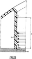
- the points P1 and P'1, respectively P2 and P'2 are separated by a distance in a straight line d , which is here of the order of 50 to 100 millimeters ( Figure 2B ).
- the distance, along the inner wall 124, respectively 126, following the sinuosity of the undulations 136, 138, between the points of the zone Z1 and the points of the zone Z 1, respectively the points of the zone Z2 and those of the zone Z'2, always remains greater than or equal to 400 millimeters, preferably between 400 and 800 millimeters, more preferably between 600 and 800 millimeters.
- the distance D between the point P1 and the point P'1, respectively P2 and P'2 is greater than or equal to 400 millimeters ( Figure 2B ).
- the distance D is at least 200% larger than the distance d , preferably 300% greater than the distance d .
- the undulations 136, 138 make it possible to double or even triple the distance in a straight line d .
- the inner walls (without the corrugations) are flat, so that the distance d can be measured along the inner walls.
- the upstream upper portion 100B also includes the roof 102 which at this location does not include a frame, but only the arch roof structure 102A.
- the upstream upper part 100B comprises a first electrical equipment mounted on the roof 102, and more specifically directly on the arch roof structure 102A.
- the electrical equipment is a circuit breaker 140.
- the circuit breaker 140 comprises two connectors 142 and 144 connected, respectively, to two electric cables 146 and 148, via, respectively, two disc insulators 150 and 152.
- the upper upstream portion 100B further comprises a second insulating cowling 154 rising from the roof 102, and comprising an insulating wall 156 which covers the whole of the upstream upper part 100B, and in particular the electrical equipment arranged on the roof 102, for example the circuit breaker 140 and the electrical cables 146 and 148.
- the insulating wall 156 is disposed at a very short distance above the electrical equipment of the upstream upper part 100B.
- the insulating wall 156 is provided, on an internal face 157, oriented towards the roof 102, with corrugations 158 arranged so as to avoid the occurrence of arcing between high voltage points of the electrical equipment and low voltage points. electrical equipment (particularly electric masses) which would pass along the insulating wall 156.
- the corrugations are configured to extend between the areas of the insulating wall 156 located entirely within 100 mm, preferably within 150 mm of the high voltage points, and the areas of the insulating wall 156 located entirely less than 100 mm, preferably less than 150 mm, of the low voltage points, the potential difference between the high voltage points and the low voltage points being 5000 volts or more.
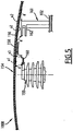
- the upper upstream portion 100B comprises a first electrical equipment 161 comprising a conductor 162 may be at low voltage, for example connected to ground and a second electrical equipment 159 comprising a conductor 160 may be, when operation of the equipment 159, high voltage (5,000 volts or more).
- a zone U1 of the insulating wall 156 is less than 150 mm (distance "a '" on the figure 5 ) of the high voltage conductor 160.
- This zone U1 comprises in particular the point X1 which is the point of U1 closest to the conductor 160.
- a zone U2 of the insulating wall 156 is less than 150 mm (distance "a '" on the figure 5 ) of the low voltage conductor 162.
- the zone U2 comprises in particular a point X2 closest to the element 162.
- part of the zone U1 is less than 100 millimeters in a straight line from the zone U2, and vice versa.
- the points X1 and X2 are separated by a distance d of less than 400 millimeters. There could therefore be a risk of occurrence of an electric arc propagating along the wall 156 between the conductors 160 and 162.
- undulations 158 are disposed on the inner surface of the insulating wall 156 so as to succeed one another between the two zones U1 and U2.
- These corrugations 156 have the effect that the zones U1 and U2 are separated by a distance greater than or equal to 400 millimeters, preferably between 400 and 800 millimeters, along the wall 156 following the sinuosity of the corrugations 158.
- the points X1 and X2 are separated by a distance D, along the wall 156, greater than 400 millimeters.
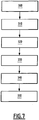
- a method of manufacturing the upper portion 100A comprises the following steps.
- acroteres identical to those of Figures 1 to 3 , except that they are devoid of the corrugations 136, 138, are arranged in the predetermined position illustrated on the Figures 1 to 4 .
- This step can be performed for real, for example by manufacturing a prototype or a draft of the final product.
- This step can also be performed virtually, for example by computer simulation or by calculations. In the illustrated example, this step is performed by computer simulation.
- a step 210 it is determined, on the walls 124, 126 thus arranged, the zones located less than 100 millimeters from the reinforcement 106 (zones Z1 and Z2), and those located within 100 mm of the roof 102 (zones Z'1 and Z'2), preferably less than 150 millimeters.
- a first point of the wall 124, respectively 126, closest to the armature 106 (point P1 belonging by definition to the zone Z1, respectively point P2 belonging to the zone Z2), and a second point of the wall 124, respectively 126, closest to the roof 102 (point P'1 belonging by definition to the zone Z'1, respectively point P'2 belonging to the zone Z'2), are also determined during this step. Similarly, this step is performed either in real life or in a virtual way.
- the distance in a straight line (that is to say in the example illustrated, along the inner wall 124, 126, plane) between the two points of the zone Z1 and those of the zone Z2, respectively between the points of the zone Z'1 and those of the zone Z'2, is compared with a predetermined value, 400 millimeters in the illustrated example.
- a predetermined value 400 millimeters in the illustrated example.
- the distance d in a straight line between the first and second points P1, P'1, P2 and P'2 is compared to the predetermined value.
- the predetermined value comes from a standard.
- the straight line distances above are not always greater than the predetermined value, so that there is a risk of breakdown propagating along the walls. This is particularly the case when the distance d in a straight line between the two points P1 and P'1, P2 and P'2 is less than the predetermined value.
- a step 230 there is provided on the inner wall 124, 126, one or more waves (s) between the two zones Z1 and Z'1, Z2 and Z'2, and therefore, in particular, between the two points P1 and P'1, P2 and P'2, so that the distance between two points of these two zones, along the wall thus provided with the wave or waves, becomes greater than or equal to the predetermined value.
- the distance D between the two points P1 and P'1, P2 and P'2 becomes greater than or equal to 400 millimeters.
- a step 240 the wall with, in this case, the wave or waves, is manufactured.
- This step leads to the actual obtaining of the acroteres 120 and 122, and, more generally, to the actual obtaining of the walls 124 and 126.
- this step comprises the manufacture by molding in one piece of the rollover 118 (as shown on the figure 3 ) with the inner walls 124 and 126 provided with the corrugations 136 and 138.
- the upper part of the railway vehicle is manufactured by placing the acroters 120 and 122 thus manufactured in the predetermined position as illustrated in FIGS. Figures 1 to 4 , and therefore also by arranging the inner walls 124 and 126 in their predetermined position, as illustrated in the Figures 1 to 3 .
- the second cowling 154 is designed in a similar manner.
- an insulating wall 156 'intended to form the wall 156 of the second casing 158 is considered, and, consequently, intended to be arranged in a predetermined position in which the insulating wall is close to the first and second electrical conductors likely to be, at a time of operation of the rail vehicle, respective potentials whose difference is greater than 5,000 volts.
- one or more first zone (s) located within 100 millimeters, preferably less than 150 millimeters, of the first high-voltage conductor are determined.
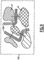
- one or more second zone (s) within 100 millimeters, preferably less than 150 millimeters, of the second low-voltage conductor, when the wall insulation is in its predetermined position is illustrated on the figure 8 , with the first zones (high voltage) indicated in simple hatching and the second zones (low voltage) indicated in crossed hatching. Areas U1 and U2 of the figure 5 are indicated. It will be noted that each of the points of the insulating wall 156 'closest to the high-voltage and low-voltage conductors are, by construction, in the zones thus determined.
- the distance between the first zones and the second zones is compared to a predetermined value T of 400 millimeters in the example illustrated. As is visible on the figure 8 the first zones are at a distance less than the predetermined value T of the second zones.
- corrugations 158' are provided between the first and second zones, so that the distance between the first zones and the second zones, along the wall insulation thus provided with corrugations, becomes greater than or equal to the predetermined value.
- the result of this step is illustrated on the figure 9 .
- This step has the particular result that the points on the insulating wall closest to the high voltage and low voltage conductors are separated by a distance greater than or equal to 400 millimeters, preferably between 400 and 800 millimeters, in particular between 600 and 800 millimeters.
- steps 300 to 330 can be performed in real, or virtually, for example by computer simulation.
- the wall 156 provided with the corrugations 158 is produced from the wall 156 'and the corrugations 158' provided.
- the upstream upper part 100B of the railway vehicle 99 is produced by disposing the wall 156 thus manufactured in the predetermined position, as shown in FIGS. figures 1 , 4 and 5 .
- the invention makes it possible to have a fairing in the immediate vicinity of the electrical equipment provided on the roof of a railway vehicle.
- the fairing may delimit a housing suitable for receiving overhead electrical equipment, such as a pantograph.
- the invention reduces the spacing between the electrical equipment, so that one gains in compactness.
- the cowling is provided with inspection hatches for easy access to the covered electrical equipment.
- These traps are generally identified by the number 400 on the figures 1 and 3 .
- these hatches are made of a transparent material to form windows facilitating inspection and maintenance operations.
- the invention makes it possible to reduce the aerodynamic turbulence and the acoustics of the railway vehicle by making it possible to have a rollover of suitable shapes, as close as possible to the electrical equipment, without having to space these electrical equipment from one another.
Landscapes
- Engineering & Computer Science (AREA)
- Mechanical Engineering (AREA)
- Wood Science & Technology (AREA)
- Life Sciences & Earth Sciences (AREA)
- Transportation (AREA)
- Architecture (AREA)
- Structural Engineering (AREA)
- Physics & Mathematics (AREA)
- Civil Engineering (AREA)
- Electromagnetism (AREA)
- Power Engineering (AREA)
- Current-Collector Devices For Electrically Propelled Vehicles (AREA)
- Linear Motors (AREA)
Description
La présente invention concerne une partie de véhicule ferroviaire, un véhicule ferroviaire et un procédé de fabrication d'une partie d'un véhicule ferroviaire.The present invention relates to a railway vehicle part, a railway vehicle and a method of manufacturing a part of a railway vehicle.
Le document
De manière générale, tous les trains ou locomotives présentent une partie dégagée du toit, c'est-à-dire non recouverte par un capot, destinée à recevoir l'ensemble des équipements haute tension de toit du véhicule ferroviaire, tels qu'un pantographe, un disjoncteur haute tension, différents sectionneurs pour configurer les circuits d'alimentation ou de mise à la masse, des systèmes de protection (parafoudre,....), etc.In general, all the trains or locomotives have an open part of the roof, that is to say not covered by a hood, intended to receive all high voltage roof equipment of the railway vehicle, such as a pantograph , a high-voltage circuit-breaker, various disconnectors to configure the supply or grounding circuits, protection systems (surge arresters, ....), etc.
Ces équipements haute tension comprennent habituellement des conducteurs électriques à l'air libre (par exemple des contacts) susceptibles, lors du fonctionnement du véhicule ferroviaire, de se trouver à des potentiels dont la différence, soit entre eux, soit avec le toit qui est généralement utilisé comme conducteur de masse électrique, peut être supérieure à 5 000 volts.These high voltage equipment usually include electrical conductors in the open air (eg contacts) likely, during operation of the railway vehicle, to be at potentials whose difference between them or with the roof which is generally used as an electrical ground conductor, may be greater than 5,000 volts.
La partie dégagée du toit est entourée latéralement d'acrotères sensiblement verticaux, et, en amont et en aval, par des capots intégraux, c'est-à-dire recouvrant entièrement le toit. Ainsi, la partie dégagée du toit se trouve dans une « baignoire ». Celle-ci génère des turbulences aérodynamiques qui dégradent l'acoustique et l'aérodynamique du véhicule. En outre, cette partie dégagée du toit, de part la taille de la baignoire, est très mal protégée des intempéries.The unobstructed portion of the roof is surrounded laterally by substantially vertical acroters, and upstream and downstream by integral covers, that is to say completely covering the roof. Thus, the unobstructed portion of the roof is in a "bathtub". This generates aerodynamic turbulence that degrades the acoustics and aerodynamics of the vehicle. In addition, this part of the roof, due to the size of the bath, is very poorly protected from the weather.
Il existe donc un besoin pour un véhicule ferroviaire permettant de concevoir une forme en baignoire de taille réduite, tout en assurant les isolements nécessaires entre les différents conducteurs, particulièrement pour les véhicules alimentés par la haute tension.There is therefore a need for a railway vehicle to design a small bathtub shape, while ensuring the necessary insulation between the various drivers, especially for vehicles powered by high voltage.
A cet effet, l'invention a pour objets une partie de véhicule ferroviaire conforme à l'une des revendications 1 à 8 et un véhicule ferroviaire conforme à la revendication 9.For this purpose, the subject of the invention is a railway vehicle part according to one of claims 1 to 8 and a railway vehicle according to claim 9.
Grâce à l'invention, il est possible de disposer une paroi isolante au plus prêt des conducteurs électriques, tout en gardant un faible risque de formation d'un arc électrique, par exemple par claquage, le long de la paroi isolante, entre deux conducteurs. Par exemple, les acrotères peuvent être rapprochés des équipements présents dans la partie dégagée du toit, ce qui permet de réduire la dimension de la baignoire.Thanks to the invention, it is possible to have an insulating wall at the ready of the electrical conductors, while keeping a low risk of forming an electric arc, for example by breakdown, along the insulating wall, between two drivers. For example, acroteria can be brought closer to the equipment in the open roof, reducing the size of the bathtub.
Encore un autre avantage de l'invention réside dans le fait qu'il est possible de garder les dispositifs électriques proches les uns des autres, malgré la proximité de la paroi isolante.Yet another advantage of the invention lies in the fact that it is possible to keep the electrical devices close to each other, despite the proximity of the insulating wall.
Les caractéristiques et avantages de l'invention, ainsi que d'autres, seront illustrés dans la description qui va suivre d'un exemple préféré de réalisation de l'invention. La description fait référence aux dessins annexés, parmi lesquels :
- la
figure 1 est une vue en trois dimensions d'un véhicule ferroviaire selon l'invention ; - la
figure 2A est une vue en coupe transversale d'une partie supérieure aval de lafigure 1 ; et lafigure 2B est une vue agrandie de la zone Il de lafigure 2A ; - la
figure 3 est une vue isolée en trois dimensions d'un capotage de la partie supérieure de lafigure 2 ; - la
figure 4 est une vue en coupe transversale d'une partie supérieure amont du véhicule ferroviaire de lafigure 1 , illustrant un exemple comparatif n'appartenant pas à l'invention ; - la
figure 5 est une autre vue en coupe transversale de la partie supérieure amont, illustrant un exemple comparatif n'appartenant pas à l'invention ; - les
figures 6 et7 sont des vues schématiques des étapes de procédés de fabrication de la partie supérieure de lafigure 2 ; et, - les
figures 8 et9 sont des représentations virtuelles des zones de haute et basse tension de la partie supérieure de lafigure 2 .
- the
figure 1 is a three-dimensional view of a railway vehicle according to the invention; - the
Figure 2A is a cross-sectional view of a downstream upper part of thefigure 1 ; and theFigure 2B is an enlarged view of area II of theFigure 2A ; - the
figure 3 is an isolated three-dimensional view of a cowling of the upper part of thefigure 2 ; - the
figure 4 is a cross-sectional view of an upstream upper part of the railway vehicle of thefigure 1 illustrating a comparative example not belonging to the invention; - the
figure 5 is another cross-sectional view of the upper upstream portion, illustrating a comparative example not belonging to the invention; - the
figures 6 and7 are schematic views of the manufacturing process steps of the upper part of thefigure 2 ; and, - the
figures 8 and9 are virtual representations of the high and low voltage areas of the upper part of thefigure 2 .
Dans la description qui va suivre, une distance dite « en ligne droite » entre deux éléments signifie une distance sans tenir compte des obstacles physiques entre ces deux éléments. Une distance entre deux points d'une paroi, dite évaluée « le long » de la paroi, signifie qu'il s'agit de la plus courte des distances curvilignes évaluées le long des lignes à la surface de la paroi qui passent par ces deux points. La ligne correspondant à cette distance la plus courte est dite « ligne de fuite » par analogie avec l'utilisation de l'expression « ligne de fuite » dans le domaine des isolateurs électriques.In the following description, a distance called "in a straight line" between two elements means a distance without taking into account the physical obstacles between these two elements. A distance between two points of a wall, said to be evaluated "along" the wall, means that it is the shortest of the curvilinear distances evaluated along the lines on the surface of the wall that pass through these two points. The line corresponding to this shortest distance is called "creepage" by analogy with the use of the expression "creepage" in the field of electrical insulators.
En référence à la
Le véhicule ferroviaire 99 comprend un toit 102 (aussi appelé pavillon), qui est conducteur électrique, et qui s'étend sensiblement horizontalement, en particulier sous la partie supérieure aval 100A et sous la partie supérieure amont 100B du véhicule ferroviaire 99. Le toit 102 forme un premier conducteur électrique. Le toit 102 est par exemple utilisé comme conducteur de masse électrique.The
En référence à la
En référence aux
Trois isolateurs 112, 114 et 116 maintiennent l'armature 106 sur le toit 102. Chacun de ces isolateurs 112, 114, 116 comprend un empilement de disques isolant, de manière à éviter la formation d'un arc électrique entre l'armature 106 et le toit 102, le long de ces isolateurs.Three
L'armature 106 comprend des fixations 106A et 106B avec les isolateurs 112, 114. Ces fixations 106A, 106B sont également conductrices et au même potentiel que le reste de l'armature 106.The
La partie supérieure aval 100A comprend en outre un premier capotage isolant 118 entourant le pantographe 104, de manière à former un logement ouvert par au-dessus, aussi dénommé « baignoire », à l'intérieur duquel est disposé le pantographe 104The upper
Plus précisément, le premier capotage 118 comprend deux acrotères latéraux 120, 122, qui s'élèvent du toit 102. Chaque acrotère 120, 122 comprend une paroi interne 124, 126 sensiblement verticale et orientée vers le pantographe, et une paroi externe 128, 130 qui s'élève depuis l'un des bords latéraux 132, 134 du véhicule ferroviaire, jusqu'à rejoindre la paroi interne 124, 126 correspondantes. Les parois internes 124, 126 comprennent des portions avals sensiblement parallèles à la direction longitudinale générale du véhicule ferroviaire et des portions amont, s'étendant en biais par rapport à la direction longitudinale et se rejoignant en amont du pantographe 104 de sorte que le pantographe 104 est entouré latéralement et en amont. En revanche, le côté aval du pantographe 104 reste ouvert. Dans un autre mode de réalisation non représenté, le côté aval est également fermé.More specifically, the
Chaque paroi interne 124, 126, est munie d'ondulations 136, 138, formées, dans l'exemple illustré, par des nervures qui s'étendent d'amont en aval sur la paroi interne 124, 126, et qui se succèdent verticalement. De manière générale, les ondulations 136, 138, peuvent avoir une section transversale de forme quelconque, notamment de forme en ailette, mais sont définies par deux points d'inflexions successifs définissant deux changements de sens de courbure. De préférence, il est prévu au moins six nervures. En variante, les ondulations peuvent être formées par des rainures ménagées dans les parois internes 124 et 126.Each
De préférence, comme cela est représenté sur les figures, le premier capotage 118 est constitué d'une seule pièce, par exemple moulée. En particulier, les ondulations 136 et 138 font partie intégrante, c'est-à-dire venues de matières avec les parois internes 124 et 126.Preferably, as shown in the figures, the
En variante, le capotage 118 comprend plusieurs pièces fixées les unes aux autres, par exemple par collage et/ou par fixation mécanique. Par exemple, les ondulations sont rapportées sur les parois internes 124 et 126. Avantageusement, dans ces cas, le matériau constitutif des ondulations est choisi de manière à constituer un meilleur isolant électrique que le matériau constitutif des parois.Alternatively, the
Chaque paroi interne 124, 126, s'étend à proximité de l'armature 106 du pantographe 104, de manière à diminuer la dimension de la « baignoire » où s'étend le pantographe. Cette proximité de l'armature a pour conséquence qu'il existe, sur chaque paroi interne 124, 126, une zone Z1, respectivement Z2, entièrement située à moins de 150 millimètres, en ligne droite, de l'armature 106 (dans l'exemple illustré, des fixations 106A et 106B de l'armature 106). Dans l'exemple illustré, les zones Z1 et Z2 sont situées à moins de 100 millimètres en ligne droite de l'armature 106 (distance « a » sur les figures). La zone Z1, respectivement la zone Z2, comprend, en particulier, un point P1, respectivement P2, le plus proche de l'armature 106 (dans l'exemple illustré des fixations 106A, 106B).Each
De la même manière, il existe sur chaque paroi interne 124, 126, une zone Z'1, respectivement Z'2, située entièrement à moins de 150 millimètres en ligne droite du toit 102 (à moins de 100 millimètres en ligne droite du châssis 102B dans l'exemple illustré, distance « a » sur les figures). En particulier, les parois internes 124 et 126 étant en contact avec le toit 102, la zone Z'1, respectivement la zone Z'2, comprend le point P'1, respectivement P'2, en contact avec le toit 102, ce point étant donc le point de Z'1, Z'2, le plus proche du toit 102.In the same way, there exists on each
La distance en ligne droite entre les points de la zone Z1 et ceux de la zone Z'1 est relativement faible. En particulier, les points P1 et P'1, respectivement P2 et P'2, sont séparés d'une distance en ligne droite d, qui est ici de l'ordre de 50 à 100 millimètres (
Cependant, grâce à la présence des ondulations 136, 138, la distance, le long de la paroi interne 124, respectivement 126, en suivant la sinuosité des ondulations 136, 138, entre les points de la zone Z1 et les points de la zone Z'1, respectivement les points de la zone Z2 et ceux de la zone Z'2, reste toujours supérieure ou égale à 400 millimètres, de préférence compris entre 400 et 800 millimètres, de préférence encore entre 600 et 800 millimètres. En particulier, la distance D entre le point P1 et le point P'1, respectivement P2 et P'2, est supérieure ou égale à 400 millimètres (
Ainsi, malgré la proximité entre les parois internes 124, 126, et des équipements électriques présentant, entre eux, une différence de potentiel élevée, le risque d'apparition d'un arc électrique entre l'armature 106 et le toit 102 qui passerait le long de la paroi interne 124, 126, est faible.Thus, despite the proximity between the
De préférence, la distance D est au moins 200% plus grande que la distance d, de préférence 300% plus grande de la distance d. Ainsi, les ondulations 136, 138 permettent de doubler, voire même tripler, la distance en ligne droite d. Dans l'exemple illustré, les parois internes (sans les ondulations) sont planes, de sorte que la distance d peut être mesurée le long des parois internes.Preferably, the distance D is at least 200% larger than the distance d , preferably 300% greater than the distance d . Thus, the
En référence aux
En référence à la
La partie supérieure amont 100B comprend en outre un second capotage isolant 154 s'élevant du toit 102, et comprenant une paroi isolante 156 qui recouvre l'ensemble de la partie supérieure amont 100B, et en particulier les équipements électriques disposés sur le toit 102, par exemple le disjoncteur 140 et les câbles électriques 146 et 148. La paroi isolante 156 est disposée à très faible distance au-dessus des équipements électriques de la partie supérieure amont 100B.The upper
Comme cela est visible sur la
En particulier, les ondulations sont configurées pour s'étendre entre les zones de la paroi isolante 156 situées entièrement à moins de 100 mm, de préférence à moins de 150 mm des points à haute tension, et les zones de la paroi isolante 156 situées entièrement à moins de 100 mm, de préférence à moins de 150 mm des points à basse tension, la différence de potentiel entre les points à haute tension et les points à basse tension étant de 5 000 volts ou plus.In particular, the corrugations are configured to extend between the areas of the insulating
Ainsi, en référence à la
Comme la paroi isolante 156 est disposée proche des premier et second équipements électriques, une zone U1 de la paroi isolante 156 se trouve à moins de 150 mm (distance « a' » sur la
Une zone U2 de la paroi isolante 156 se trouve à moins de 150 mm (distance « a' » sur la
Or, une partie de la zone U1 se trouve à moins de 100 millimètres en ligne droite de la zone U2, et inversement. En particulier, les points X1 et X2 sont séparés d'une distance d inférieure à 400 millimètres. Il pourrait donc exister un risque de survenue d'un arc électrique se propageant le long de la paroi 156 entre les conducteurs 160 et 162.However, part of the zone U1 is less than 100 millimeters in a straight line from the zone U2, and vice versa. In particular, the points X1 and X2 are separated by a distance d of less than 400 millimeters. There could therefore be a risk of occurrence of an electric arc propagating along the
Pour pallier ce risque, comme cela est visible sur la
En référence à la
Au cours d'une étape 200, des acrotères identiques à ceux des
Au cours d'une étape 210, il est déterminé, sur les parois 124, 126 ainsi disposées, les zones situées à moins de 100 millimètres de l'armature 106 (zones Z1 et Z2), et celles situées à moins de 100 mm du toit 102 (zones Z'1 et Z'2), de préférence à moins de 150 millimètres. Un premier point de la paroi 124, respectivement 126, le plus proche de l'armature 106 (point P1 appartenant par définition à la zone Z1, respectivement point P2 appartenant à la zone Z2), et un second point de la paroi 124, respectivement 126, le plus proche du toit 102 (point P'1 appartenant par définition à la zone Z'1, respectivement point P'2 appartenant à la zone Z'2), sont également déterminés au cours de cette étape. De même, cette étape est réalisée soit en vrai, soit de manière virtuelle.During a
Au cours d'une étape 220, la distance en ligne droite (c'est-à-dire dans l'exemple illustré, le long de la paroi interne 124, 126, plane) entre les deux points de la zone Z1 et ceux de la zone Z2, respectivement entre les points de la zone Z'1 et ceux de la zone Z'2, est comparée à une valeur prédéterminée, 400 millimètres dans l'exemple illustré. En particulier, la distance d en ligne droite entre les premier et second points P1, P'1, P2 et P'2 est comparée à la valeur prédéterminée. De préférence la valeur prédéterminée est issue d'une norme.During a
Comme les parois n'ont pas d'ondulations et qu'elles sont positionnées au plus près des équipements électriques, les distances en ligne droite précédentes ne sont pas toujours supérieures à la valeur prédéterminée, de sorte qu'il existe un risque de claquage se propageant le long des parois. C'est en particulier le cas lorsque la distance d en ligne droite entre les deux points P1 et P'1, P2 et P'2, est inférieure à la valeur prédéterminée.As the walls have no undulations and they are positioned closer to the electrical equipment, the straight line distances above are not always greater than the predetermined value, so that there is a risk of breakdown propagating along the walls. This is particularly the case when the distance d in a straight line between the two points P1 and P'1, P2 and P'2 is less than the predetermined value.
Au cours d'une étape 230, on prévoit sur la paroi interne 124, 126, une ou plusieurs ondulation(s) entre les deux zones Z1 et Z'1, Z2 et Z'2, et donc, en particulier, entre les deux points P1 et P'1, P2 et P'2, afin que la distance entre deux points de ces deux zones, le long de la paroi ainsi munie de la ou des ondulations, devienne supérieure ou égale à la valeur prédéterminée. En particulier, la distance D entre les deux points P1 et P'1, P2 et P'2 devient supérieure ou égale à 400 millimètres.During a
Au cours d'une étape 240, la paroi avec, dans le cas présent, la ou les ondulations, est fabriquée. Cette étape aboutit à l'obtention réelle des acrotères 120 et 122, et, de manière plus générale, à l'obtention réelle des parois 124 et 126. Dans l'exemple illustré, cette étape comprend la fabrication par moulage en une seule pièce du capotage 118 (tel qu'il est représenté sur la
Au cours d'une étape 250, la partie supérieure du véhicule ferroviaire est fabriquée en disposant les acrotères 120 et 122 ainsi fabriqués dans la position prédéterminée telle qu'illustrée sur les
Le second capotage 154 est conçu d'une manière analogue.The
En référence à la
Au cours d'une étape 310, on détermine, sur la paroi isolante 156', une ou plusieurs première(s) zone(s) situées à moins de 100 millimètres, de préférence à moins de 150 millimètres, du premier conducteur à haute tension, et une ou plusieurs seconde(s) zone(s) situées à moins de 100 millimètres, de préférence à moins de 150 millimètres, du second conducteur à basse tension, lorsque la paroi isolante est dans sa position prédéterminée. Le résultat de cette étape est illustré sur la
Au cours d'une étape 320, on compare, le long de la paroi isolante 156', la distance entre les premières zones et les secondes zones à une valeur prédéterminée T, de 400 millimètres dans l'exemple illustré. Comme cela est visible sur la
En conséquence, au cours d'une étape 330, on prévoit, sur la paroi isolante 156', des ondulations 158' entre les premières et secondes zones, afin que la distance entre les premières zones et les secondes zones, le long de la paroi isolante ainsi munie d'ondulations, devienne supérieure ou égale à la valeur prédéterminée. Le résultat de cette étape est illustré sur la
On remarquera que les étapes 300 à 330 peuvent être réalisées en vrai, ou bien de manière virtuelle, par exemple par simulation sur ordinateur.It will be noted that the
Au cours d'une étape 340, on fabrique la paroi 156 munie des ondulations 158, à partir de la paroi 156' et des ondulations 158' prévues.During a
Enfin, au cours d'une étape 350, on fabrique la partie supérieure amont 100B du véhicule ferroviaire 99 en disposant la paroi 156 ainsi fabriquée dans la position prédéterminée, telle que représentée sur les
L'invention permet de disposer un carénage à proximité immédiate des équipements électriques prévus sur le toit d'un véhicule ferroviaire. Le carénage peut délimiter un logement adapté à la réception d'équipements électriques aériens, tels qu'un pantographe.The invention makes it possible to have a fairing in the immediate vicinity of the electrical equipment provided on the roof of a railway vehicle. The fairing may delimit a housing suitable for receiving overhead electrical equipment, such as a pantograph.
De plus, l'invention permet de réduire l'espacement entre les équipements électriques, de sorte que l'on gagne en compacité.In addition, the invention reduces the spacing between the electrical equipment, so that one gains in compactness.
Avantageusement, le capotage est muni de trappes de visite permettant d'accéder facilement aux équipements électriques recouverts. Ces trappes sont repérées de manière générale par le chiffre 400 sur les
Ainsi, l'invention permet de réduire les turbulences aérodynamiques et l'acoustique du véhicule ferroviaire en permettant de disposer un capotage aux formes adaptées, au plus près des équipements électriques, sans avoir besoin d'espacer ces équipements électriques les uns des autres.Thus, the invention makes it possible to reduce the aerodynamic turbulence and the acoustics of the railway vehicle by making it possible to have a rollover of suitable shapes, as close as possible to the electrical equipment, without having to space these electrical equipment from one another.
Claims (9)
- A railway vehicle part of the type comprising:- A roof (102) that is electrically conductive;- first and second electrical conductors (102, 106) able to be at respective potentials the difference of which is greater than 5,000 volts at an operating moment of the railway vehicle, the roof constituting the first electrical conductor and a pantograph constituting the second electrical conductor (106), the second electric conductor (106) being fixed on the roof (102) with an isolator;- an insulating cowling (118) rising from the roof and surrounding the pantograph (104) so as to form a housing open at the top, also called "tub", inside which the pantograph (104) is arranged, the cowling comprises an internal wall;- said internal wall constituting an insulating wall (124; 126) extending away from at least one of the first and second conductors (102, 106), having a first point (P1; P2; X1) closest to the second electrical conductor (106) and a second point (P'1; P'2; X2) closest to the first electrical conductor (102),the railway vehicle part being characterised in that the insulating wall (124; 126) comprises at least one undulation (136; 138), in particular plurality of undulations, between the first and second points (P1, P'1; P2, P'2; X1, X2) such that the first and second points (P1, P'1; P2, P'2; X1, X2) are separated along the insulating wall (124; 126) by a predetermined distance (D) such as to avoid the occurrence of electric arcs between the first and second electrical conductors.
- The railway vehicle part according to claim 1, characterised in that at least one undulation among the undulation or the plurality of undulations (136; 138) is integral with the wall (124; 128).
- The railway vehicle part according to claim 1, characterised in that at least one undulation among the undulation or the plurality of undulations `136; 138) is applied to the wall (124; 126).
- The railway vehicle part according to claim 3, characterised in that the material of said at least one applied undulation is more insulating than the material forming the wall.
- The railway vehicle part according to any of the preceding claims, characterised furthermore in that said predetermined distance (D) is at least 400 millimetres, preferably between 400 and 800 metres, preferably between 600 and 800 millimetres.
- The railway vehicle part according to any of the preceding claims, characterised furthermore in that the first and second points (P1, P'1; P2, P'2; X1, X2) are separated by a distance d in a straight line, and in that the distance D is at least 200% greater than the distance d, preferably 300% greater than the distance d.
- The railway vehicle part according to any of the preceding claims, characterised furthermore in that the first point, respectively the second point, is located less than 150 millimetres away from the first conductor, respectively the second conductor, preferably less than 100 millimetres away.
- The railway vehicle part according to any of the preceding claims, characterised furthermore in that a first zone of the wall is located at least 100 millimetres away, preferably at least 150 millimetres away, from the first conductor, in that a second zone of the wall is located less than 100 millimetres, preferably less than 150 millimetres away from the second conductor, and in that the first and second zones are separated by at least 400 millimetres.
- A railway vehicle comprising a part according to any of claims 1 to 8.
Applications Claiming Priority (1)
| Application Number | Priority Date | Filing Date | Title |
|---|---|---|---|
| FR1050337A FR2955304B1 (en) | 2010-01-19 | 2010-01-19 | RAILWAY VEHICLE AND METHOD FOR MANUFACTURING THE SAME |
Publications (4)
| Publication Number | Publication Date |
|---|---|
| EP2394878A2 EP2394878A2 (en) | 2011-12-14 |
| EP2394878A3 EP2394878A3 (en) | 2012-02-22 |
| EP2394878B1 EP2394878B1 (en) | 2013-04-17 |
| EP2394878B2 true EP2394878B2 (en) | 2016-12-07 |
Family
ID=42671555
Family Applications (1)
| Application Number | Title | Priority Date | Filing Date |
|---|---|---|---|
| EP11305050.4A Active EP2394878B2 (en) | 2010-01-19 | 2011-01-18 | Railway vehicle and corresponding manufacturing method |
Country Status (5)
| Country | Link |
|---|---|
| EP (1) | EP2394878B2 (en) |
| KR (1) | KR101794780B1 (en) |
| CN (1) | CN102152742B (en) |
| FR (1) | FR2955304B1 (en) |
| RU (1) | RU2553604C2 (en) |
Families Citing this family (12)
| Publication number | Priority date | Publication date | Assignee | Title |
|---|---|---|---|---|
| CN102717809B (en) * | 2012-06-12 | 2015-06-17 | 唐山轨道客车有限责任公司 | Protecting cover of vehicular roof equipment and carriage of railway vehicle |
| CN104670045B (en) * | 2013-12-03 | 2017-02-15 | 中车大连电力牵引研发中心有限公司 | Vehicle hauling system |
| DE102015212175A1 (en) * | 2015-06-30 | 2017-01-05 | Siemens Aktiengesellschaft | Railway vehicle of regional or high-speed traffic with roof-side aerodynamic elements |
| DE102015218176B3 (en) * | 2015-09-22 | 2017-01-05 | Siemens Aktiengesellschaft | Vehicle, in particular rail vehicle |
| CN111152806B (en) * | 2018-11-08 | 2021-06-29 | 中车唐山机车车辆有限公司 | Roof air guide sleeve, railway vehicle and roof air guide sleeve installation method |
| SG11202008009YA (en) * | 2019-02-26 | 2020-10-29 | Crrc Changchun Railway Vehicles Co Ltd | Motor train unit and pantograph platform structure thereof |
| CN109649177A (en) * | 2019-02-26 | 2019-04-19 | 中车长春轨道客车股份有限公司 | EMU and its pantograph platform structure |
| DE102020205958A1 (en) * | 2020-05-12 | 2021-11-18 | Bombardier Transportation Gmbh | Rail vehicle and method for manufacturing a rail vehicle |
| AT526523B1 (en) * | 2023-04-28 | 2024-04-15 | Siemens Mobility Austria Gmbh | Roof hood for a rail vehicle |
| US20250187444A1 (en) * | 2023-12-06 | 2025-06-12 | Progress Rail Locomotive Inc. | Insulated Feed-Through Connector |
| DE102024206957A1 (en) * | 2024-02-05 | 2025-08-07 | Siemens Mobility GmbH | Arrangement in particular for a car body of a track-guided vehicle |
| DE102024202863A1 (en) * | 2024-03-26 | 2025-10-02 | Siemens Mobility GmbH | Arrangement to protect a person from electrical contact |
Citations (2)
| Publication number | Priority date | Publication date | Assignee | Title |
|---|---|---|---|---|
| JPH05328513A (en) † | 1992-05-14 | 1993-12-10 | Kinki Sharyo Co Ltd | Pantograph cover |
| JP4386253B2 (en) † | 2003-02-18 | 2009-12-16 | 東海旅客鉄道株式会社 | Pantograph device |
Family Cites Families (8)
| Publication number | Priority date | Publication date | Assignee | Title |
|---|---|---|---|---|
| RU2025313C1 (en) * | 1991-03-28 | 1994-12-30 | Омский Институт Инженеров Железнодорожного Транспорта | Current-collecting device for electrified rolling stock |
| JPH05176403A (en) * | 1991-12-25 | 1993-07-13 | Shimadzu Corp | Railway vehicle current collector |
| EP0605214B1 (en) * | 1992-12-28 | 1997-11-19 | Hitachi, Ltd. | High speed low noise current collecting equipment |
| JP3374469B2 (en) * | 1993-10-26 | 2003-02-04 | 株式会社日立製作所 | Current collector |
| DE19713816A1 (en) * | 1997-04-03 | 1998-10-15 | Siemens Ag | Rail vehicle |
| KR20010106403A (en) * | 1998-07-14 | 2001-11-29 | 헬무트 할비히 | Rail vehicle, especially self-propelled rail vehicle |
| KR200425738Y1 (en) * | 2006-06-27 | 2006-09-06 | 주식회사 아이텍코리아 | Noise reduction device with current collector insulation |
| CN201099182Y (en) * | 2007-09-10 | 2008-08-13 | 武汉钢铁(集团)公司 | Power supply device for electric flat carriage |
-
2010
- 2010-01-19 FR FR1050337A patent/FR2955304B1/en active Active
-
2011
- 2011-01-18 RU RU2011101742/11A patent/RU2553604C2/en active
- 2011-01-18 EP EP11305050.4A patent/EP2394878B2/en active Active
- 2011-01-19 KR KR1020110005207A patent/KR101794780B1/en active Active
- 2011-01-19 CN CN201110058386.8A patent/CN102152742B/en active Active
Patent Citations (2)
| Publication number | Priority date | Publication date | Assignee | Title |
|---|---|---|---|---|
| JPH05328513A (en) † | 1992-05-14 | 1993-12-10 | Kinki Sharyo Co Ltd | Pantograph cover |
| JP4386253B2 (en) † | 2003-02-18 | 2009-12-16 | 東海旅客鉄道株式会社 | Pantograph device |
Non-Patent Citations (1)
| Title |
|---|
| Norme DIN EN 501 24-1 † |
Also Published As
| Publication number | Publication date |
|---|---|
| EP2394878A2 (en) | 2011-12-14 |
| KR20110085921A (en) | 2011-07-27 |
| FR2955304A1 (en) | 2011-07-22 |
| CN102152742B (en) | 2016-01-27 |
| RU2011101742A (en) | 2012-07-27 |
| FR2955304B1 (en) | 2014-06-20 |
| KR101794780B1 (en) | 2017-12-01 |
| CN102152742A (en) | 2011-08-17 |
| EP2394878A3 (en) | 2012-02-22 |
| RU2553604C2 (en) | 2015-06-20 |
| EP2394878B1 (en) | 2013-04-17 |
Similar Documents
| Publication | Publication Date | Title |
|---|---|---|
| EP2394878B1 (en) | Railway vehicle and corresponding manufacturing method | |
| FR2924685A1 (en) | PARAFOUDRE AND AIRCRAFT SYSTEM COMPRISING SUCH A SYSTEM. | |
| FR2926920A1 (en) | ELECTRICITY INSULATING DISK FOR SUPPORTING A LINEAR CONDUCTOR AND ELECTRICAL ASSEMBLY COMPRISING THE DISK. | |
| EP0868737B1 (en) | Device for connecting an external conductor such as a cable to a contact of an electrical apparatus | |
| EP2810286A1 (en) | Positioning spacer, energy storage module using said spacer and method for assembling the module | |
| EP3836765B1 (en) | Electrical insulation module for high-voltage electrical equipment | |
| WO2014154786A1 (en) | Self-deicing lightweight conductor | |
| EP3888154A1 (en) | Battery case and modular battery system | |
| FR2977085A1 (en) | DEVICE FOR ELECTRICALLY CONNECTING AT LEAST ONE CONDUCTOR RESPECTIVELY AT LEAST ONE CONTACT RANGE OF AN ELECTRICAL APPARATUS AND AN ELECTRIC APPARATUS COMPRISING SAME. | |
| WO2004015830A2 (en) | Protective device for electric power distribution network | |
| FR2883425A1 (en) | Synthetic D.C. cable end for connecting medium or high voltage electrical cable to transmission line, has insert, shaped as cable duct surrounding insulator on unsheathed end of cable, placed between inner insulator and outer sleeve | |
| WO2019077076A1 (en) | Cage for female electrical contact | |
| WO2012131180A1 (en) | Dielectric element for a high-voltage insulator with a high tensile strength | |
| EP3097634B1 (en) | Isolation device for collector of electric machine, corresponding collector and alternator | |
| FR2974676A1 (en) | CONNECTING SLEEVE FOR ELECTRIC CABLES | |
| EP2733011B1 (en) | Fitting of catenary | |
| FR2968138A1 (en) | ELECTRICAL CONNECTION ASSEMBLY FORMED BY HIGH VOLTAGE ELECTRIC CABLE AND CONNECTING DEVICE | |
| CN212783214U (en) | Pressure equalizers and circuit breakers | |
| FR2854001A1 (en) | Insulating bushing for overhead medium voltage transmission line interrupter, has insulating part including zone with truncated surface that cooperates with two flanges to apply flanges on wall of interrupter, around opening | |
| FR2880604A1 (en) | RAILWAY VEHICLE WITH HIGH ROOF ROOFING EQUIPMENT | |
| FR3012659A1 (en) | ELECTRIC CURRENT CONDUCTING DEVICE AND METHOD OF MANUFACTURING SUCH CONDUCTION DEVICE | |
| WO2018001891A1 (en) | Connecting connector | |
| EP2771897B2 (en) | Arc quench chamber provided with a tube for limiting the impact of the particle generation, and electrical switching apparatus provided with such an arc quench chamber | |
| FR2963172A1 (en) | ELECTRICITY TRANSPORT LINE WITH GAS INSULATION | |
| FR2786360A1 (en) | Multi-terminal cable connection module for any type of electrical apparatus, has terminal connections separated by internal insulated walls |
Legal Events
| Date | Code | Title | Description |
|---|---|---|---|
| AK | Designated contracting states |
Kind code of ref document: A2 Designated state(s): AL AT BE BG CH CY CZ DE DK EE ES FI FR GB GR HR HU IE IS IT LI LT LU LV MC MK MT NL NO PL PT RO RS SE SI SK SM TR |
|
| AX | Request for extension of the european patent |
Extension state: BA ME |
|
| PUAI | Public reference made under article 153(3) epc to a published international application that has entered the european phase |
Free format text: ORIGINAL CODE: 0009012 |
|
| PUAL | Search report despatched |
Free format text: ORIGINAL CODE: 0009013 |
|
| AK | Designated contracting states |
Kind code of ref document: A3 Designated state(s): AL AT BE BG CH CY CZ DE DK EE ES FI FR GB GR HR HU IE IS IT LI LT LU LV MC MK MT NL NO PL PT RO RS SE SI SK SM TR |
|
| AX | Request for extension of the european patent |
Extension state: BA ME |
|
| RIC1 | Information provided on ipc code assigned before grant |
Ipc: B60L 5/18 20060101ALI20120113BHEP Ipc: B61D 17/12 20060101ALI20120113BHEP Ipc: B61D 17/02 20060101AFI20120113BHEP |
|
| 17P | Request for examination filed |
Effective date: 20120822 |
|
| GRAP | Despatch of communication of intention to grant a patent |
Free format text: ORIGINAL CODE: EPIDOSNIGR1 |
|
| GRAS | Grant fee paid |
Free format text: ORIGINAL CODE: EPIDOSNIGR3 |
|
| GRAA | (expected) grant |
Free format text: ORIGINAL CODE: 0009210 |
|
| AK | Designated contracting states |
Kind code of ref document: B1 Designated state(s): AL AT BE BG CH CY CZ DE DK EE ES FI FR GB GR HR HU IE IS IT LI LT LU LV MC MK MT NL NO PL PT RO RS SE SI SK SM TR |
|
| REG | Reference to a national code |
Ref country code: GB Ref legal event code: FG4D Free format text: NOT ENGLISH |
|
| REG | Reference to a national code |
Ref country code: CH Ref legal event code: EP |
|
| REG | Reference to a national code |
Ref country code: IE Ref legal event code: FG4D Free format text: LANGUAGE OF EP DOCUMENT: FRENCH |
|
| REG | Reference to a national code |
Ref country code: AT Ref legal event code: REF Ref document number: 607084 Country of ref document: AT Kind code of ref document: T Effective date: 20130515 |
|
| REG | Reference to a national code |
Ref country code: DE Ref legal event code: R096 Ref document number: 602011001395 Country of ref document: DE Effective date: 20130606 |
|
| REG | Reference to a national code |
Ref country code: SE Ref legal event code: TRGR |
|
| RAP2 | Party data changed (patent owner data changed or rights of a patent transferred) |
Owner name: ALSTOM TRANSPORT TECHNOLOGIES |
|
| RAP2 | Party data changed (patent owner data changed or rights of a patent transferred) |
Owner name: ALSTOM TRANSPORT TECHNOLOGIES SAS |
|
| REG | Reference to a national code |
Ref country code: NL Ref legal event code: T3 |
|
| REG | Reference to a national code |
Ref country code: AT Ref legal event code: MK05 Ref document number: 607084 Country of ref document: AT Kind code of ref document: T Effective date: 20130417 |
|
| REG | Reference to a national code |
Ref country code: LT Ref legal event code: MG4D |
|
| PG25 | Lapsed in a contracting state [announced via postgrant information from national office to epo] |
Ref country code: AT Free format text: LAPSE BECAUSE OF FAILURE TO SUBMIT A TRANSLATION OF THE DESCRIPTION OR TO PAY THE FEE WITHIN THE PRESCRIBED TIME-LIMIT Effective date: 20130417 Ref country code: GR Free format text: LAPSE BECAUSE OF FAILURE TO SUBMIT A TRANSLATION OF THE DESCRIPTION OR TO PAY THE FEE WITHIN THE PRESCRIBED TIME-LIMIT Effective date: 20130718 Ref country code: NO Free format text: LAPSE BECAUSE OF FAILURE TO SUBMIT A TRANSLATION OF THE DESCRIPTION OR TO PAY THE FEE WITHIN THE PRESCRIBED TIME-LIMIT Effective date: 20130717 Ref country code: SI Free format text: LAPSE BECAUSE OF FAILURE TO SUBMIT A TRANSLATION OF THE DESCRIPTION OR TO PAY THE FEE WITHIN THE PRESCRIBED TIME-LIMIT Effective date: 20130417 Ref country code: LT Free format text: LAPSE BECAUSE OF FAILURE TO SUBMIT A TRANSLATION OF THE DESCRIPTION OR TO PAY THE FEE WITHIN THE PRESCRIBED TIME-LIMIT Effective date: 20130417 Ref country code: PT Free format text: LAPSE BECAUSE OF FAILURE TO SUBMIT A TRANSLATION OF THE DESCRIPTION OR TO PAY THE FEE WITHIN THE PRESCRIBED TIME-LIMIT Effective date: 20130819 Ref country code: ES Free format text: LAPSE BECAUSE OF FAILURE TO SUBMIT A TRANSLATION OF THE DESCRIPTION OR TO PAY THE FEE WITHIN THE PRESCRIBED TIME-LIMIT Effective date: 20130728 Ref country code: IS Free format text: LAPSE BECAUSE OF FAILURE TO SUBMIT A TRANSLATION OF THE DESCRIPTION OR TO PAY THE FEE WITHIN THE PRESCRIBED TIME-LIMIT Effective date: 20130817 Ref country code: FI Free format text: LAPSE BECAUSE OF FAILURE TO SUBMIT A TRANSLATION OF THE DESCRIPTION OR TO PAY THE FEE WITHIN THE PRESCRIBED TIME-LIMIT Effective date: 20130417 |
|
| RAP2 | Party data changed (patent owner data changed or rights of a patent transferred) |
Owner name: ALSTOM TRANSPORT TECHNOLOGIES |
|
| PG25 | Lapsed in a contracting state [announced via postgrant information from national office to epo] |
Ref country code: BG Free format text: LAPSE BECAUSE OF FAILURE TO SUBMIT A TRANSLATION OF THE DESCRIPTION OR TO PAY THE FEE WITHIN THE PRESCRIBED TIME-LIMIT Effective date: 20130717 Ref country code: HR Free format text: LAPSE BECAUSE OF FAILURE TO SUBMIT A TRANSLATION OF THE DESCRIPTION OR TO PAY THE FEE WITHIN THE PRESCRIBED TIME-LIMIT Effective date: 20130417 Ref country code: LV Free format text: LAPSE BECAUSE OF FAILURE TO SUBMIT A TRANSLATION OF THE DESCRIPTION OR TO PAY THE FEE WITHIN THE PRESCRIBED TIME-LIMIT Effective date: 20130417 Ref country code: PL Free format text: LAPSE BECAUSE OF FAILURE TO SUBMIT A TRANSLATION OF THE DESCRIPTION OR TO PAY THE FEE WITHIN THE PRESCRIBED TIME-LIMIT Effective date: 20130417 Ref country code: RS Free format text: LAPSE BECAUSE OF FAILURE TO SUBMIT A TRANSLATION OF THE DESCRIPTION OR TO PAY THE FEE WITHIN THE PRESCRIBED TIME-LIMIT Effective date: 20130417 Ref country code: CY Free format text: LAPSE BECAUSE OF FAILURE TO SUBMIT A TRANSLATION OF THE DESCRIPTION OR TO PAY THE FEE WITHIN THE PRESCRIBED TIME-LIMIT Effective date: 20130417 |
|
| PLBI | Opposition filed |
Free format text: ORIGINAL CODE: 0009260 |
|
| PG25 | Lapsed in a contracting state [announced via postgrant information from national office to epo] |
Ref country code: CZ Free format text: LAPSE BECAUSE OF FAILURE TO SUBMIT A TRANSLATION OF THE DESCRIPTION OR TO PAY THE FEE WITHIN THE PRESCRIBED TIME-LIMIT Effective date: 20130417 Ref country code: DK Free format text: LAPSE BECAUSE OF FAILURE TO SUBMIT A TRANSLATION OF THE DESCRIPTION OR TO PAY THE FEE WITHIN THE PRESCRIBED TIME-LIMIT Effective date: 20130417 Ref country code: EE Free format text: LAPSE BECAUSE OF FAILURE TO SUBMIT A TRANSLATION OF THE DESCRIPTION OR TO PAY THE FEE WITHIN THE PRESCRIBED TIME-LIMIT Effective date: 20130417 Ref country code: SK Free format text: LAPSE BECAUSE OF FAILURE TO SUBMIT A TRANSLATION OF THE DESCRIPTION OR TO PAY THE FEE WITHIN THE PRESCRIBED TIME-LIMIT Effective date: 20130417 |
|
| PLAX | Notice of opposition and request to file observation + time limit sent |
Free format text: ORIGINAL CODE: EPIDOSNOBS2 |
|
| 26 | Opposition filed |
Opponent name: BOMBARDIER TRANSPORTATION GMBH Effective date: 20140117 Opponent name: SIEMENS AKTIENGESELLSCHAFT Effective date: 20140117 |
|
| PG25 | Lapsed in a contracting state [announced via postgrant information from national office to epo] |
Ref country code: RO Free format text: LAPSE BECAUSE OF FAILURE TO SUBMIT A TRANSLATION OF THE DESCRIPTION OR TO PAY THE FEE WITHIN THE PRESCRIBED TIME-LIMIT Effective date: 20130417 |
|
| REG | Reference to a national code |
Ref country code: NL Ref legal event code: SD Effective date: 20140226 |
|
| REG | Reference to a national code |
Ref country code: DE Ref legal event code: R082 Ref document number: 602011001395 Country of ref document: DE Representative=s name: LAVOIX MUNICH, DE Effective date: 20140213 Ref country code: DE Ref legal event code: R081 Ref document number: 602011001395 Country of ref document: DE Owner name: ALSTOM TRANSPORT TECHNOLOGIES, FR Free format text: FORMER OWNER: ALSTOM TRANSPORT SA, LEVALLOIS-PERRET, FR Effective date: 20140213 |
|
| REG | Reference to a national code |
Ref country code: DE Ref legal event code: R026 Ref document number: 602011001395 Country of ref document: DE Effective date: 20140117 |
|
| REG | Reference to a national code |
Ref country code: FR Ref legal event code: TP Owner name: ALSTOM TRANSPORT TECHNOLOGIES, FR Effective date: 20140505 |
|
| PLAF | Information modified related to communication of a notice of opposition and request to file observations + time limit |
Free format text: ORIGINAL CODE: EPIDOSCOBS2 |
|
| BERE | Be: lapsed |
Owner name: ALSTOM TRANSPORT SA Effective date: 20140131 |
|
| PG25 | Lapsed in a contracting state [announced via postgrant information from national office to epo] |
Ref country code: LU Free format text: LAPSE BECAUSE OF FAILURE TO SUBMIT A TRANSLATION OF THE DESCRIPTION OR TO PAY THE FEE WITHIN THE PRESCRIBED TIME-LIMIT Effective date: 20140118 |
|
| REG | Reference to a national code |
Ref country code: CH Ref legal event code: PL |
|
| PLBB | Reply of patent proprietor to notice(s) of opposition received |
Free format text: ORIGINAL CODE: EPIDOSNOBS3 |
|
| PG25 | Lapsed in a contracting state [announced via postgrant information from national office to epo] |
Ref country code: CH Free format text: LAPSE BECAUSE OF NON-PAYMENT OF DUE FEES Effective date: 20140131 Ref country code: LI Free format text: LAPSE BECAUSE OF NON-PAYMENT OF DUE FEES Effective date: 20140131 |
|
| REG | Reference to a national code |
Ref country code: IE Ref legal event code: MM4A |
|
| PG25 | Lapsed in a contracting state [announced via postgrant information from national office to epo] |
Ref country code: BE Free format text: LAPSE BECAUSE OF NON-PAYMENT OF DUE FEES Effective date: 20140131 Ref country code: IE Free format text: LAPSE BECAUSE OF NON-PAYMENT OF DUE FEES Effective date: 20140118 |
|
| PLAB | Opposition data, opponent's data or that of the opponent's representative modified |
Free format text: ORIGINAL CODE: 0009299OPPO |
|
| R26 | Opposition filed (corrected) |
Opponent name: SIEMENS AKTIENGESELLSCHAFT Effective date: 20140117 |
|
| PG25 | Lapsed in a contracting state [announced via postgrant information from national office to epo] |
Ref country code: MC Free format text: LAPSE BECAUSE OF FAILURE TO SUBMIT A TRANSLATION OF THE DESCRIPTION OR TO PAY THE FEE WITHIN THE PRESCRIBED TIME-LIMIT Effective date: 20130417 |
|
| GBPC | Gb: european patent ceased through non-payment of renewal fee |
Effective date: 20150118 |
|
| PG25 | Lapsed in a contracting state [announced via postgrant information from national office to epo] |
Ref country code: GB Free format text: LAPSE BECAUSE OF NON-PAYMENT OF DUE FEES Effective date: 20150118 |
|
| REG | Reference to a national code |
Ref country code: FR Ref legal event code: PLFP Year of fee payment: 6 |
|
| PG25 | Lapsed in a contracting state [announced via postgrant information from national office to epo] |
Ref country code: MT Free format text: LAPSE BECAUSE OF FAILURE TO SUBMIT A TRANSLATION OF THE DESCRIPTION OR TO PAY THE FEE WITHIN THE PRESCRIBED TIME-LIMIT Effective date: 20130417 |
|
| APBM | Appeal reference recorded |
Free format text: ORIGINAL CODE: EPIDOSNREFNO |
|
| APBP | Date of receipt of notice of appeal recorded |
Free format text: ORIGINAL CODE: EPIDOSNNOA2O |
|
| APAH | Appeal reference modified |
Free format text: ORIGINAL CODE: EPIDOSCREFNO |
|
| PG25 | Lapsed in a contracting state [announced via postgrant information from national office to epo] |
Ref country code: SM Free format text: LAPSE BECAUSE OF FAILURE TO SUBMIT A TRANSLATION OF THE DESCRIPTION OR TO PAY THE FEE WITHIN THE PRESCRIBED TIME-LIMIT Effective date: 20130417 |
|
| APBU | Appeal procedure closed |
Free format text: ORIGINAL CODE: EPIDOSNNOA9O |
|
| PG25 | Lapsed in a contracting state [announced via postgrant information from national office to epo] |
Ref country code: HU Free format text: LAPSE BECAUSE OF FAILURE TO SUBMIT A TRANSLATION OF THE DESCRIPTION OR TO PAY THE FEE WITHIN THE PRESCRIBED TIME-LIMIT; INVALID AB INITIO Effective date: 20110118 Ref country code: TR Free format text: LAPSE BECAUSE OF FAILURE TO SUBMIT A TRANSLATION OF THE DESCRIPTION OR TO PAY THE FEE WITHIN THE PRESCRIBED TIME-LIMIT Effective date: 20130417 |
|
| RAP2 | Party data changed (patent owner data changed or rights of a patent transferred) |
Owner name: ALSTOM TRANSPORT TECHNOLOGIES |
|
| PUAH | Patent maintained in amended form |
Free format text: ORIGINAL CODE: 0009272 |
|
| STAA | Information on the status of an ep patent application or granted ep patent |
Free format text: STATUS: PATENT MAINTAINED AS AMENDED |
|
| 27A | Patent maintained in amended form |
Effective date: 20161207 |
|
| AK | Designated contracting states |
Kind code of ref document: B2 Designated state(s): AL AT BE BG CH CY CZ DE DK EE ES FI FR GB GR HR HU IE IS IT LI LT LU LV MC MK MT NL NO PL PT RO RS SE SI SK SM TR |
|
| REG | Reference to a national code |
Ref country code: DE Ref legal event code: R102 Ref document number: 602011001395 Country of ref document: DE |
|
| REG | Reference to a national code |
Ref country code: FR Ref legal event code: PLFP Year of fee payment: 7 |
|
| PG25 | Lapsed in a contracting state [announced via postgrant information from national office to epo] |
Ref country code: LV Free format text: LAPSE BECAUSE OF FAILURE TO SUBMIT A TRANSLATION OF THE DESCRIPTION OR TO PAY THE FEE WITHIN THE PRESCRIBED TIME-LIMIT Effective date: 20161207 |
|
| REG | Reference to a national code |
Ref country code: NL Ref legal event code: FP |
|
| REG | Reference to a national code |
Ref country code: SE Ref legal event code: RPEO |
|
| REG | Reference to a national code |
Ref country code: DE Ref legal event code: R082 Ref document number: 602011001395 Country of ref document: DE Representative=s name: LAVOIX MUNICH, DE Ref country code: DE Ref legal event code: R081 Ref document number: 602011001395 Country of ref document: DE Owner name: ALSTOM TRANSPORT TECHNOLOGIES, FR Free format text: FORMER OWNER: ALSTOM TRANSPORT TECHNOLOGIES, LEVALLOIS-PERRET, FR |
|
| REG | Reference to a national code |
Ref country code: FR Ref legal event code: PLFP Year of fee payment: 8 |
|
| REG | Reference to a national code |
Ref country code: FR Ref legal event code: CA Effective date: 20180103 |
|
| PG25 | Lapsed in a contracting state [announced via postgrant information from national office to epo] |
Ref country code: MK Free format text: LAPSE BECAUSE OF FAILURE TO SUBMIT A TRANSLATION OF THE DESCRIPTION OR TO PAY THE FEE WITHIN THE PRESCRIBED TIME-LIMIT Effective date: 20130417 |
|
| PG25 | Lapsed in a contracting state [announced via postgrant information from national office to epo] |
Ref country code: AL Free format text: LAPSE BECAUSE OF FAILURE TO SUBMIT A TRANSLATION OF THE DESCRIPTION OR TO PAY THE FEE WITHIN THE PRESCRIBED TIME-LIMIT Effective date: 20130417 |
|
| P01 | Opt-out of the competence of the unified patent court (upc) registered |
Effective date: 20231025 |
|
| PGFP | Annual fee paid to national office [announced via postgrant information from national office to epo] |
Ref country code: NL Payment date: 20250121 Year of fee payment: 15 |
|
| PGFP | Annual fee paid to national office [announced via postgrant information from national office to epo] |
Ref country code: DE Payment date: 20250121 Year of fee payment: 15 |
|
| PGFP | Annual fee paid to national office [announced via postgrant information from national office to epo] |
Ref country code: SE Payment date: 20250121 Year of fee payment: 15 |
|
| PGFP | Annual fee paid to national office [announced via postgrant information from national office to epo] |
Ref country code: FR Payment date: 20250127 Year of fee payment: 15 |
|
| PGFP | Annual fee paid to national office [announced via postgrant information from national office to epo] |
Ref country code: IT Payment date: 20250129 Year of fee payment: 15 |