EP2394878B1 - Schienenfahrzeug und entsprechendes Herstellungsverfahren - Google Patents
Schienenfahrzeug und entsprechendes Herstellungsverfahren Download PDFInfo
- Publication number
- EP2394878B1 EP2394878B1 EP11305050.4A EP11305050A EP2394878B1 EP 2394878 B1 EP2394878 B1 EP 2394878B1 EP 11305050 A EP11305050 A EP 11305050A EP 2394878 B1 EP2394878 B1 EP 2394878B1
- Authority
- EP
- European Patent Office
- Prior art keywords
- railway vehicle
- wall
- distance
- vehicle part
- conductor
- Prior art date
- Legal status (The legal status is an assumption and is not a legal conclusion. Google has not performed a legal analysis and makes no representation as to the accuracy of the status listed.)
- Active
Links
Images


Classifications
-
- B—PERFORMING OPERATIONS; TRANSPORTING
- B61—RAILWAYS
- B61D—BODY DETAILS OR KINDS OF RAILWAY VEHICLES
- B61D17/00—Construction details of vehicle bodies
- B61D17/04—Construction details of vehicle bodies with bodies of metal; with composite, e.g. metal and wood body structures
-
- B—PERFORMING OPERATIONS; TRANSPORTING
- B60—VEHICLES IN GENERAL
- B60L—PROPULSION OF ELECTRICALLY-PROPELLED VEHICLES; SUPPLYING ELECTRIC POWER FOR AUXILIARY EQUIPMENT OF ELECTRICALLY-PROPELLED VEHICLES; ELECTRODYNAMIC BRAKE SYSTEMS FOR VEHICLES IN GENERAL; MAGNETIC SUSPENSION OR LEVITATION FOR VEHICLES; MONITORING OPERATING VARIABLES OF ELECTRICALLY-PROPELLED VEHICLES; ELECTRIC SAFETY DEVICES FOR ELECTRICALLY-PROPELLED VEHICLES
- B60L5/00—Current collectors for power supply lines of electrically-propelled vehicles
- B60L5/18—Current collectors for power supply lines of electrically-propelled vehicles using bow-type collectors in contact with trolley wire
-
- B—PERFORMING OPERATIONS; TRANSPORTING
- B61—RAILWAYS
- B61D—BODY DETAILS OR KINDS OF RAILWAY VEHICLES
- B61D17/00—Construction details of vehicle bodies
- B61D17/02—Construction details of vehicle bodies reducing air resistance by modifying contour ; Constructional features for fast vehicles sustaining sudden variations of atmospheric pressure, e.g. when crossing in tunnels
-
- B—PERFORMING OPERATIONS; TRANSPORTING
- B61—RAILWAYS
- B61D—BODY DETAILS OR KINDS OF RAILWAY VEHICLES
- B61D17/00—Construction details of vehicle bodies
- B61D17/04—Construction details of vehicle bodies with bodies of metal; with composite, e.g. metal and wood body structures
- B61D17/12—Roofs
-
- B—PERFORMING OPERATIONS; TRANSPORTING
- B61—RAILWAYS
- B61D—BODY DETAILS OR KINDS OF RAILWAY VEHICLES
- B61D49/00—Other details
-
- E—FIXED CONSTRUCTIONS
- E04—BUILDING
- E04B—GENERAL BUILDING CONSTRUCTIONS; WALLS, e.g. PARTITIONS; ROOFS; FLOORS; CEILINGS; INSULATION OR OTHER PROTECTION OF BUILDINGS
- E04B1/00—Constructions in general; Structures which are not restricted either to walls, e.g. partitions, or floors or ceilings or roofs
- E04B1/62—Insulation or other protection; Elements or use of specified material therefor
-
- B—PERFORMING OPERATIONS; TRANSPORTING
- B60—VEHICLES IN GENERAL
- B60L—PROPULSION OF ELECTRICALLY-PROPELLED VEHICLES; SUPPLYING ELECTRIC POWER FOR AUXILIARY EQUIPMENT OF ELECTRICALLY-PROPELLED VEHICLES; ELECTRODYNAMIC BRAKE SYSTEMS FOR VEHICLES IN GENERAL; MAGNETIC SUSPENSION OR LEVITATION FOR VEHICLES; MONITORING OPERATING VARIABLES OF ELECTRICALLY-PROPELLED VEHICLES; ELECTRIC SAFETY DEVICES FOR ELECTRICALLY-PROPELLED VEHICLES
- B60L2200/00—Type of vehicles
- B60L2200/26—Rail vehicles
-
- Y—GENERAL TAGGING OF NEW TECHNOLOGICAL DEVELOPMENTS; GENERAL TAGGING OF CROSS-SECTIONAL TECHNOLOGIES SPANNING OVER SEVERAL SECTIONS OF THE IPC; TECHNICAL SUBJECTS COVERED BY FORMER USPC CROSS-REFERENCE ART COLLECTIONS [XRACs] AND DIGESTS
- Y02—TECHNOLOGIES OR APPLICATIONS FOR MITIGATION OR ADAPTATION AGAINST CLIMATE CHANGE
- Y02T—CLIMATE CHANGE MITIGATION TECHNOLOGIES RELATED TO TRANSPORTATION
- Y02T30/00—Transportation of goods or passengers via railways, e.g. energy recovery or reducing air resistance
Definitions
- the present invention relates to a railway vehicle part, a railway vehicle and a method of manufacturing a part of a railway vehicle.
- the document JP-A-5 176 403 discloses a railway vehicle part according to the preamble of claim 1.
- all the trains or locomotives have an open part of the roof, that is to say not covered by a hood, intended to receive all high voltage roof equipment of the railway vehicle, such as a pantograph , a high-voltage circuit-breaker, various disconnectors to configure the supply or grounding circuits, protection systems (surge arresters, ....), etc.
- These high voltage equipment usually include electrical conductors in the open air (eg contacts) likely, during operation of the railway vehicle, to be at potentials whose difference between them or with the roof which is generally used as an electrical ground conductor, may be greater than 5,000 volts.
- the unobstructed portion of the roof is surrounded laterally by substantially vertical acroters, and upstream and downstream by integral covers, that is to say completely covering the roof.
- the unobstructed portion of the roof is in a "bathtub". This generates aerodynamic turbulence that degrades the acoustics and aerodynamics of the vehicle.
- this part of the roof due to the size of the bath, is very poorly protected from the weather.
- the subject of the invention is a railway vehicle part according to one of claims 1 to 13, a railway vehicle according to claim 14, and manufacturing methods, respectively, according to claims 15 and 16.
- the invention it is possible to have an insulating wall at the ready of the electrical conductors, while keeping a low risk of forming an electric arc, for example by breakdown, along the insulating wall, between two conductors .
- acroteria can be brought closer to equipment in the open roof area, which reduces the size of the bath.
- Another advantage of the invention is to allow the design of insulating walls forming a cover over some high voltage electrical equipment.
- Yet another advantage of the invention lies in the fact that it is possible to keep the electrical devices close to each other, despite the proximity of the insulating wall.
- a distance called “in a straight line” between two elements means a distance without taking into account the physical obstacles between these two elements.
- a distance between two points of a wall, said to be evaluated “along” the wall, means that it is the shortest of the curvilinear distances evaluated along the lines on the surface of the wall that pass through these two points.
- the line corresponding to this shortest distance is called “line leakage “by analogy with the use of the expression” creepage "in the field of electrical insulators.
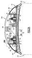
- the railway vehicle 99 comprises an upper part 100A downstream, partially open, and a top upstream portion 100B covered.
- the railway vehicle 99 comprises a roof 102 (also called roof), which is electrically conductive, and which extends substantially horizontally, in particular under the upper downstream part 100A and under the upper upstream part 100B of the railway vehicle 99.
- the roof 102 forms a first electrical conductor.
- the roof 102 is for example used as an electrical ground conductor.
- the roof 102 includes a roof structure 102A, in an arc, and a frame 102B, in the form of a horizontal plate, the frame 102B being mounted on the roof structure 102A. Both elements 102A and 102B are electrically conductive and in electrical contact with each other. As previously stated, they are used as mass.
- the railway vehicle further comprises a pantograph 104 disposed on the roof 102, in the downstream part 100A, where the roof 102 is intended to remain clear, that is to say not covered by a hood, as will be apparent by the following.
- the pantograph 104 comprises a fixed armature 106, an articulated structure 108 mounted on the armature 106, and a bow 110 carried by the structure 108 and intended to come into contact with a catenary (not shown) to electrically power the railway vehicle 99
- armature 106 Each of these elements 106, 108 and 110, and in particular the armature 106, form second electrical conductors, which may be at a moment of operation of the railway vehicle at potentials greater than 5000 volts with respect to roof 102, for example 12,000 volts or 25,000 volts.
- Three isolators 112, 114 and 116 hold the armature 106 on the roof 102.
- Each of these insulators 112, 114, 116 comprises a stack of insulating discs, so as to avoid the formation of an electric arc between the armature 106 and the roof 102, along these insulators.
- the armature 106 comprises fasteners 106A and 106B with the insulators 112, 114. These fasteners 106A, 106B are also conductive and at the same potential as the rest of the armature 106.
- the upper downstream portion 100A further comprises a first insulating cowling 118 surrounding the pantograph 104, so as to form a housing open from above, also called “bathtub", inside which is disposed the pantograph 104
- the first cowling 118 comprises two lateral acroters 120, 122, which rise from the roof 102.
- Each acroterium 120, 122 comprises an inner wall 124, 126 substantially vertical and facing the pantograph, and an outer wall 128, 130 which rises from one of the lateral edges 132, 134 of the railway vehicle, to reach the corresponding inner wall 124, 126.
- the internal walls 124, 126 comprise downstream portions substantially parallel to the general longitudinal direction of the railway vehicle and upstream portions, extending obliquely with respect to the longitudinal direction and meeting upstream of the pantograph 104 so that the pantograph 104 is surrounded laterally and upstream.
- the downstream side of the pantograph 104 remains open. In another embodiment not shown, the downstream side is also closed.
- Each inner wall 124, 126 is provided with corrugations 136, 138, formed, in the example illustrated, by ribs which extend from upstream to downstream on the inner wall 124, 126, and which follow one another vertically.
- the corrugations 136, 138 may have a cross section of any shape, in particular of fin shape, but are defined by two successive points of inflection defining two changes of direction of curvature.
- at least six ribs are provided.
- the corrugations may be formed by grooves in the inner walls 124 and 126.
- the first cowling 118 consists of a single piece, for example molded.
- the corrugations 136 and 138 are integral, that is to say, come from materials with the inner walls 124 and 126.
- the cowling 118 comprises a plurality of pieces fixed to each other, for example by gluing and / or by mechanical fastening.
- the corrugations are reported on the inner walls 124 and 126.
- the constituent material of the corrugations is chosen so as to constitute a better electrical insulator than the material constituting the walls.
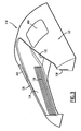
- Each inner wall 124, 126 extends near the armature 106 of the pantograph 104, so as to reduce the size of the "bath" where the pantograph extends.
- This proximity of the armature has the consequence that there exists, on each inner wall 124, 126, a zone Z1, respectively Z2, entirely located less than 150 millimeters, in a straight line, of the armature 106 (in the illustrated example, fasteners 106A and 106B of the frame 106).
- the zones Z1 and Z2 are located less than 100 millimeters in a straight line of the armature 106 (distance "a" in the figures).
- the zone Z1, zone Z2, respectively comprises, in particular, a point P1, respectively P2, closest to the armature 106 (in the illustrated example of the fasteners 106A, 106B).
- each inner wall 124, 126 there exists on each inner wall 124, 126, a zone Z'1, respectively Z'2, situated entirely within 150 millimeters in a straight line of the roof 102 (less than 100 millimeters in a straight line of the chassis 102B in the illustrated example, distance "a" in the figures).
- the inner walls 124 and 126 being in contact with the roof 102, the zone Z'1, respectively the zone Z'2, comprises the point P'1, respectively P'2, in contact with the roof 102, which point being therefore the point of Z'1, Z'2, closest to roof 102.
- the distance in a straight line between the points of zone Z1 and those of zone Z'1 is relatively small.
- the points P1 and P'1, respectively P2 and P'2 are separated by a distance in a straight line d , which is here of the order of 50 to 100 millimeters ( Figure 2B ).
- the distance, along the inner wall 124, respectively 126, following the sinuosity of the undulations 136, 138, between the points of the zone Z1 and the points of the zone Z 1, respectively the points of zone Z2 and those of zone Z'2 always remain greater than or equal to 400 millimeters, preferably between 400 and 800 millimeters, more preferably between 600 and 800 millimeters.
- the distance D between the point P1 and the point P'1, respectively P2 and P'2 is greater than or equal to 400 millimeters ( Figure 2B ).
- the distance D is at least 200% larger than the distance d , preferably 300% greater than the distance d .
- the undulations 136, 138 make it possible to double or even triple the distance in a straight line d .
- the inner walls (without the corrugations) are flat, so that the distance d can be measured along the inner walls.
- the upstream upper portion 100B also includes the roof 102 which at this location does not include a frame, but only the arch roof structure 102A.
- the upstream upper part 100B comprises a first electrical equipment mounted on the roof 102, and more specifically directly on the arch roof structure 102A.
- the electrical equipment is a circuit breaker 140.
- the circuit breaker 140 comprises two connectors 142 and 144 connected, respectively, to two electric cables 146 and 148, via, respectively, two disc insulators 150 and 152.
- the upper upstream portion 100B further comprises a second insulating cowling 154 rising from the roof 102, and comprising an insulating wall 156 which covers the whole of the upstream upper part 100B, and in particular the electrical equipment arranged on the roof 102, for example the circuit breaker 140 and the electrical cables 146 and 148.
- the insulating wall 156 is disposed at a very short distance above the electrical equipment of the upstream upper part 100B.
- the insulating wall 156 is provided, on an internal face 157, oriented towards the roof 102, with corrugations 158 arranged so as to avoid the occurrence of arcing between high voltage points of the electrical equipment and low voltage points. equipment electric (particularly electric masses) which would pass along the insulating wall 156.
- the corrugations are configured to extend between the areas of the insulating wall 156 located entirely within 100 mm, preferably within 150 mm of the high voltage points, and the areas of the insulating wall 156 located entirely less than 100 mm, preferably less than 150 mm, of the low voltage points, the potential difference between the high voltage points and the low voltage points being 5000 volts or more.
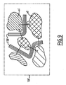
- the upper upstream portion 100B comprises a first electrical equipment 161 comprising a conductor 162 may be at low voltage, for example connected to ground and a second electrical equipment 159 comprising a conductor 160 may be, when operation of the equipment 159, high voltage (5,000 volts or more).
- a zone U1 of the insulating wall 156 is less than 150 mm (distance "a '" on the figure 5 ) of the high voltage conductor 160.
- This zone U1 comprises in particular the point X1 which is the point of U1 closest to the conductor 160.
- a zone U2 of the insulating wall 156 is less than 150 mm (distance "a '" on the figure 5 ) of the low voltage conductor 162.
- the zone U2 comprises in particular a point X2 closest to the element 162.
- part of the zone U1 is less than 100 millimeters in a straight line from the zone U2, and vice versa.
- the points X1 and X2 are separated by a distance d of less than 400 millimeters. There could therefore be a risk of occurrence of an electric arc propagating along the wall 156 between the conductors 160 and 162.
- undulations 158 are disposed on the inner surface of the insulating wall 156 so as to succeed one another between the two zones U1 and U2.
- These corrugations 156 have the effect that the zones U1 and U2 are separated by a distance greater than or equal to 400 millimeters, preferably between 400 and 800 millimeters, along the wall 156 following the sinuosity of the corrugations 158.
- the points X1 and X2 are separated by a distance D, along the wall 156, greater than 400 millimeters.
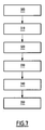
- a method according to the invention for manufacturing the upper portion 100A comprises the following steps.
- acroteres identical to those of Figures 1 to 3 , except that they are devoid of the corrugations 136, 138, are arranged in the predetermined position illustrated on the Figures 1 to 4 .
- This step can be performed for real, for example by manufacturing a prototype or a draft of the final product.
- This step can also be performed virtually, for example by computer simulation or by calculations. In the illustrated example, this step is performed by computer simulation.
- a step 210 it is determined, on the walls 124, 126 thus arranged, the zones located less than 100 millimeters from the reinforcement 106 (zones Z1 and Z2), and those located within 100 mm of the roof 102 (zones Z'1 and Z'2), preferably less than 150 millimeters.
- a first point of the wall 124, respectively 126, closest to the armature 106 (point P1 belonging by definition to the zone Z1, respectively point P2 belonging to the zone Z2), and a second point of the wall 124, respectively 126, closest to the roof 102 (point P'1 belonging by definition to the zone Z'1, respectively point P'2 belonging to the zone Z'2), are also determined during this step. Similarly, this step is performed either in real life or in a virtual way.
- the distance in a straight line (that is to say in the example illustrated, along the inner wall 124, 126, plane) between the two points of the zone Z1 and those of the zone Z2, respectively between the points of the zone Z'1 and those of the zone Z'2, is compared with a predetermined value, 400 millimeters in the illustrated example.
- a predetermined value 400 millimeters in the illustrated example.
- the distance d in a straight line between the first and second points P1, P'1, P2 and P'2 is compared to the predetermined value.
- the predetermined value comes from a standard.
- the walls have no undulations and are positioned as close as possible to the electrical equipment, the previous straight-line distances are not always greater than the predetermined value, so that there are a risk of breakdown propagating along the walls. This is particularly the case when the distance d in a straight line between the two points P1 and P'1, P2 and P'2 is less than the predetermined value.
- a step 230 there is provided on the inner wall 124, 126, one or more waves (s) between the two zones Z1 and Z'1, Z2 and Z'2, and therefore, in particular, between the two points P1 and P'1, P2 and P'2, so that the distance between two points of these two zones, along the wall thus provided with the wave or waves, becomes greater than or equal to the predetermined value.
- the distance D between the two points P1 and P'1, P2 and P'2 becomes greater than or equal to 400 millimeters.
- a step 240 the wall with, in this case, the wave or waves, is manufactured.
- This step leads to the actual obtaining of the acroteres 120 and 122, and, more generally, to the actual obtaining of the walls 124 and 126.
- this step comprises the manufacture by molding in one piece of the rollover 118 (as shown on the figure 3 ) with the inner walls 124 and 126 provided with the corrugations 136 and 138.
- the upper part of the railway vehicle is manufactured by placing the acroters 120 and 122 thus manufactured in the predetermined position as illustrated in FIGS. Figures 1 to 4 , and therefore also by arranging the inner walls 124 and 126 in their predetermined position, as illustrated in the Figures 1 to 3 .
- the second cowling 154 is designed in a similar manner.
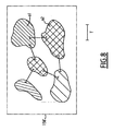
- an insulating wall 156 'intended to form the wall 156 of the second casing 158 is considered, and, consequently, intended to be arranged in a predetermined position in which the insulating wall is close to the first and second electrical conductors likely to be, at a time of operation of the rail vehicle, respective potentials whose difference is greater than 5,000 volts.
- one or more first zone (s) located within 100 millimeters, preferably less than 150 millimeters, of the first high-voltage conductor are determined.
- one or more second zone (s) within 100 millimeters, preferably less than 150 millimeters, of the second low-voltage conductor, when the insulating wall is in its predetermined position is illustrated on the figure 8 , with the first zones (high voltage) indicated in simple hatching and the second zones (low voltage) indicated in crossed hatching. Areas U1 and U2 of the figure 5 are indicated. It will be noted that each of the points of the insulating wall 156 'closest to the high-voltage and low-voltage conductors are, by construction, in the zones thus determined.
- the distance between the first zones and the second zones is compared to a predetermined value T of 400 millimeters in the example illustrated. As is visible on the figure 8 the first zones are at a distance less than the predetermined value T of the second zones.
- corrugations 158' are provided between the first and second zones, so that the distance between the first zones and the second zones, along the wall insulation thus provided with corrugations, becomes greater than or equal to the predetermined value.
- the result of this step is illustrated on the figure 9 .
- This step has the particular result that the points on the insulating wall closest to the high voltage and low voltage conductors are separated by a distance greater than or equal to 400 millimeters, preferably between 400 and 800 millimeters, in particular between 600 and 800 millimeters.
- steps 300 to 330 can be performed in real, or virtually, for example by computer simulation.
- the wall 156 provided with the corrugations 158 is produced from the wall 156 'and the corrugations 158' provided.
- the upstream upper part 100B of the railway vehicle 99 is produced by disposing the wall 156 thus manufactured in the predetermined position, as shown in FIGS. figures 1 , 4 and 5 .
- the invention makes it possible to have a fairing in the immediate vicinity of the electrical equipment provided on the roof of a railway vehicle.
- the fairing can either delimit a housing suitable for receiving overhead electrical equipment, such as a pantograph, or cover electrical equipment, such as a circuit breaker.
- the invention reduces the spacing between the electrical equipment, so that one gains in compactness.
- the cowling is provided with inspection hatches for easy access to the covered electrical equipment.
- These traps are generally identified by the number 400 on the figures 1 and 3 .
- these hatches are made of a transparent material to form windows facilitating inspection and maintenance operations.
- the invention makes it possible to reduce the aerodynamic turbulence and the acoustics of the railway vehicle by making it possible to have a rollover of suitable shapes, as close as possible to the electrical equipment, without having to space these electrical equipment from one another.
Landscapes
- Engineering & Computer Science (AREA)
- Mechanical Engineering (AREA)
- Life Sciences & Earth Sciences (AREA)
- Wood Science & Technology (AREA)
- Architecture (AREA)
- Transportation (AREA)
- Physics & Mathematics (AREA)
- Power Engineering (AREA)
- Electromagnetism (AREA)
- Civil Engineering (AREA)
- Structural Engineering (AREA)
- Current-Collector Devices For Electrically Propelled Vehicles (AREA)
- Linear Motors (AREA)
Claims (16)
- Schienenfahrzeugteil der Art, die Folgendes umfasst:- einen ersten und zweiten elektrischen Leiter (102, 106; 160, 162), die in der Lage sind, zu einem Betriebszeitpunkt des Schienenfahrzeugs ein jeweiliges Potenzial aufzuweisen, dessen Unterschied über 5 000 Volt beträgt, und- eine isolierende Wand (124; 126; 156), die im Abstand mindestens zum ersten und/oder zweiten Leiter (102, 106; 160, 162) verläuft, einen ersten Punkt (P1; P2; X1) aufweist, der dem ersten elektrischen Leiter (106; 160) am nächsten liegt, und einen zweiten Punkt (P'1; P'2; X2), der dem zweiten elektrischen Leiter (102; 162) am nächsten liegt,
wobei das Schienenfahrzeugteil dadurch gekennzeichnet ist, dass die Wand (124; 126; 156) mindestens eine Welle (136; 138; 158), insbesondere mehrere, zwischen dem ersten und zweiten Punkt (P1, P'1; P2, P'2; X1, X2) umfasst, sodass der erste und zweite Punkt (P1, P'1; P2, P'2; X1, X2) entlang der Wand (124; 126; 156) über einen festgelegten Abstand (D) getrennt sind, um das Auftreten von Lichtbögen zwischen dem ersten und zweiten elektrischen Leiter zu verhindern. - Schienenfahrzeugteil nach Anspruch 1, dadurch gekennzeichnet, dass mindestens eine Welle von der oder den Welle(n) (136; 138; 158) aus demselben Material besteht wie die Wand (124; 128; 156).
- Schienenfahrzeugteil nach Anspruch 1, dadurch gekennzeichnet, dass mindestens eine Welle von der oder den Welle(n) an der Wand (124; 126; 156) angesetzt ist.
- Schienenfahrzeugteil nach Anspruch 3, dadurch gekennzeichnet, dass das Material der mindestens einen angesetzten Welle stärker isolierend ist als das Material, aus dem die Wand besteht.
- Schienenfahrzeugteil nach einem der vorhergehenden Ansprüche, ferner dadurch gekennzeichnet, dass der festgelegte Abstand (D) mindestens 400 Millimeter, noch bevorzugter zwischen 400 und 800 Millimeter, vorzugsweise zwischen 600 und 800 Millimeter, beträgt.
- Schienenfahrzeugteil nach einem der vorhergehenden Ansprüche, ferner dadurch gekennzeichnet, dass der erste und zweite Punkt (P1, P'1; P2, P'2; X1, X2) in gerader Linie über einen Abstand d getrennt sind, und dadurch, dass der Abstand D mindestens 200 % größer ist als der Abstand d, vorzugsweise 300 % größer als der Abstand d.
- Schienenfahrzeugteil nach einem der vorhergehenden Ansprüche, ferner dadurch gekennzeichnet, dass der erste Punkt beziehungsweise der zweite Punkt weniger als 150 Millimeter vom ersten Leiter beziehungsweise zweiten Leiter entfernt ist, vorzugsweise weniger als 100 Millimeter.
- Schienenfahrzeugteil nach einem der vorhergehenden Ansprüche, ferner dadurch gekennzeichnet, dass ein erster Bereich der Wand weniger als 100 Millimeter, vorzugsweise weniger als 150 Millimeter, vom ersten Leiter entfernt ist, dadurch, dass ein zweiter Bereich der Wand weniger als 100 Millimeter, vorzugsweise weniger als 150 Millimeter, vom zweiten Leiter entfernt ist, und dadurch, dass der erste und zweite Bereich mindestens 400 Millimeter getrennt sind.
- Schienenfahrzeugteil nach einem der vorhergehenden Ansprüche, ferner dadurch gekennzeichnet, dass es ein elektrisch leitendes Dach (102) umfasst, das den ersten Leiter bildet, dadurch, dass der zweite Leiter (106) auf dem Dach angeordnet ist, und dadurch, dass er einen Isolator (112; 114; 116) umfasst, über den der zweite Leiter (106) an dem Dach (102) befestigt ist.
- Schienenfahrzeugteil nach einem der vorhergehenden Ansprüche, ferner dadurch gekennzeichnet, dass es ein Dach (102) umfasst, und dadurch, dass der erste und zweite Leiter (160, 162) auf dem Dach (102) angeordnet sind.
- Schienenfahrzeugteil nach einem der Ansprüche 9 und 10, ferner dadurch gekennzeichnet, dass es eine isolierende Verkleidung (118; 154) umfasst, die sich vom Dach (102) aus erhebt, und dadurch, dass die Verkleidung (118; 154) die isolierende Wand (124; 126; 156) umfasst.
- Schienenfahrzeugteil nach Anspruch 4, ferner dadurch gekennzeichnet, dass die Wand (156) die elektrischen Leiter (160, 162) bedeckt.
- Schienenfahrzeugteil nach Anspruch 11 oder Anspruch 12, dadurch gekennzeichnet, dass die Verkleidung, die mindestens einen Innenraum begrenzt, mindestens eine Luke für den Zugang zum Innenraum umfasst.
- Schienenfahrzeug, das ein Teil nach einem der Ansprüche 1 bis 10 umfasst.
- Verfahren zur Herstellung eines Schienenfahrzeugteils, dadurch gekennzeichnet, dass es Folgendes umfasst:- Vergleichen (220), entlang einer isolierenden Wand, die dafür bestimmt ist, in einer festgelegten Position angeordnet zu werden, in der die isolierende Wand einen Abstand zu mindestens einem Leiter von einem ersten und zweiten elektrischen Leiter aufweist, die in der Lage sind, zu einem Betriebszeitpunkt des Schienenfahrzeugs ein jeweiliges Potenzial aufzuweisen, dessen Unterschied über 5 000 Volt beträgt, des Abstands zwischen einem ersten Punkt der isolierenden Wand, der dem ersten elektrischen Leier am nächsten liegt, und einem zweiten Punkt der isolierenden Wand, der dem zweiten elektrischen Leiter am nächsten liegt, mit einem festgelegten Abstand,- wenn der Abstand zwischen dem ersten und zweiten nächstgelegenen Punkt geringer ist als der festgelegte Abstand, Vorsehen (230), an der isolierenden Wand, von mindestens einer Welle zwischen den beiden Punkten, damit der Abstand zwischen den beiden Punkten entlang der isolierenden Wand, die derart mit der Welle oder den Wellen versehen ist, größer als der festgelegte Abstand oder gleich dem festgelegten Abstand wird,- Herstellen (240) der Wand, gegebenenfalls mit der Welle oder den Wellen,- Herstellen (250) des Schienenfahrzeugteils, wobei die so hergestellte Wand in der festgelegten Position angeordnet wird.
- Verfahren zur Herstellung eines Schienenfahrzeugteils, dadurch gekennzeichnet, dass es Folgendes umfasst:- Bestimmen (310), an einer isolierenden Wand, die dafür bestimmt ist, in einer festgelegten Position angeordnet zu werden, in der die isolierende Wand einen Abstand zu mindestens einem Leiter von einem ersten und zweiten elektrischen Leiter aufweist, die in der Lage sind, zu einem Betriebszeitpunkt des Schienenfahrzeugs ein jeweiliges Potenzial aufzuweisen, dessen Unterschied über 5 000 Volt beträgt, eines ersten Bereichs, der dafür bestimmt ist, sich weniger als 100 Millimeter, vorzugsweise weniger als 150 Millimeter, vom ersten Leiter entfernt zu befinden, und eines zweiten Bereichs, der dafür bestimmt ist, sich weniger als 100 Millimeter, vorzugsweise weniger als 150 Millimeter, vom zweiten Leiter entfernt zu befinden, wenn die isolierende Wand ihre festgelegte Position aufweist,- Vergleichen (330), entlang der isolierenden Wand, des Abstands zwischen den Punkten des ersten Bereichs und den Punkten des zweiten Bereichs mit einem festgelegten Abstand,- wenn der Abstand für bestimmte Punkte des ersten und zweiten Bereichs zwischen den nächstgelegenen Punkten geringer ist als der festgelegte Abstand, Vorsehen (230), an der isolierenden Wand, von mindestens einer Welle zwischen den beiden Bereichen, damit der Abstand zwischen den Punkten der beiden Bereiche entlang der isolierenden Wand, die derart mit der Welle oder den Wellen versehen ist, größer als der festgelegte Abstand oder gleich dem festgelegten Abstand wird,- Herstellen (340) der Wand, gegebenenfalls mit der Welle oder den Wellen,- Herstellen (350) des Schienenfahrzeugteils, wobei die so hergestellte Wand in der festgelegten Position angeordnet wird.
Applications Claiming Priority (1)
| Application Number | Priority Date | Filing Date | Title |
|---|---|---|---|
| FR1050337A FR2955304B1 (fr) | 2010-01-19 | 2010-01-19 | Vehicule ferroviaire et procede de fabrication correspondant |
Publications (4)
| Publication Number | Publication Date |
|---|---|
| EP2394878A2 EP2394878A2 (de) | 2011-12-14 |
| EP2394878A3 EP2394878A3 (de) | 2012-02-22 |
| EP2394878B1 true EP2394878B1 (de) | 2013-04-17 |
| EP2394878B2 EP2394878B2 (de) | 2016-12-07 |
Family
ID=42671555
Family Applications (1)
| Application Number | Title | Priority Date | Filing Date |
|---|---|---|---|
| EP11305050.4A Active EP2394878B2 (de) | 2010-01-19 | 2011-01-18 | Schienenfahrzeug und entsprechendes Herstellungsverfahren |
Country Status (5)
| Country | Link |
|---|---|
| EP (1) | EP2394878B2 (de) |
| KR (1) | KR101794780B1 (de) |
| CN (1) | CN102152742B (de) |
| FR (1) | FR2955304B1 (de) |
| RU (1) | RU2553604C2 (de) |
Families Citing this family (11)
| Publication number | Priority date | Publication date | Assignee | Title |
|---|---|---|---|---|
| CN102717809B (zh) * | 2012-06-12 | 2015-06-17 | 唐山轨道客车有限责任公司 | 车顶设备保护罩及铁路车辆的车厢 |
| CN104670045B (zh) * | 2013-12-03 | 2017-02-15 | 中车大连电力牵引研发中心有限公司 | 车辆牵引系统 |
| DE102015212175A1 (de) * | 2015-06-30 | 2017-01-05 | Siemens Aktiengesellschaft | Schienenfahrzeug des Regional- oder Hochgeschwindigkeitsverkehrs mit dachseitigen Aerodynamikelementen |
| DE102015218176B3 (de) * | 2015-09-22 | 2017-01-05 | Siemens Aktiengesellschaft | Fahrzeug, insbesondere Schienenfahrzeug |
| CN111152806B (zh) * | 2018-11-08 | 2021-06-29 | 中车唐山机车车辆有限公司 | 车顶导流罩、轨道车辆及车顶导流罩安装方法 |
| CN109649177A (zh) * | 2019-02-26 | 2019-04-19 | 中车长春轨道客车股份有限公司 | 动车组及其受电弓平台结构 |
| EP3744558A4 (de) * | 2019-02-26 | 2021-11-10 | CRRC Changchun Railway Vehicles Co., Ltd. | Mehrgliedriger zug und stromabnehmerplattformaufbau dafür |
| DE102020205958A1 (de) * | 2020-05-12 | 2021-11-18 | Bombardier Transportation Gmbh | Schienenfahrzeug und Verfahren zur Herstellung eines Schienenfahrzeugs |
| AT526523B1 (de) * | 2023-04-28 | 2024-04-15 | Siemens Mobility Austria Gmbh | Dachhaube für ein Schienenfahrzeug |
| DE102024206957A1 (de) * | 2024-02-05 | 2025-08-07 | Siemens Mobility GmbH | Anordnung insbesondere für einen Wagenkasten eines spurgeführten Fahrzeugs |
| DE102024202863A1 (de) * | 2024-03-26 | 2025-10-02 | Siemens Mobility GmbH | Anordnung zum Schutz einer Person vor einem elektrischen Kontakt |
Family Cites Families (10)
| Publication number | Priority date | Publication date | Assignee | Title |
|---|---|---|---|---|
| RU2025313C1 (ru) * | 1991-03-28 | 1994-12-30 | Омский Институт Инженеров Железнодорожного Транспорта | Устройство токосъема для электроподвижного состава |
| JPH05176403A (ja) * | 1991-12-25 | 1993-07-13 | Shimadzu Corp | 鉄道車両用集電装置 |
| JPH05328513A (ja) † | 1992-05-14 | 1993-12-10 | Kinki Sharyo Co Ltd | パンタグラフカバー |
| EP0605214B1 (de) * | 1992-12-28 | 1997-11-19 | Hitachi, Ltd. | Geräuscharmer Stromabnehmersatz hoher Geschwindigkeit |
| JP3374469B2 (ja) * | 1993-10-26 | 2003-02-04 | 株式会社日立製作所 | 集電装置 |
| DE19713816A1 (de) * | 1997-04-03 | 1998-10-15 | Siemens Ag | Schienenfahrzeug |
| EP1097056A1 (de) * | 1998-07-14 | 2001-05-09 | Telelift GmbH | Schienenfahrzeug, insbesondere selbstfahrendes schienenfahrzeug |
| JP4386253B2 (ja) † | 2003-02-18 | 2009-12-16 | 東海旅客鉄道株式会社 | パンタグラフ装置 |
| KR200425738Y1 (ko) * | 2006-06-27 | 2006-09-06 | 주식회사 아이텍코리아 | 집전장치 절연기능을 갖는 소음저감장치 |
| CN201099182Y (zh) * | 2007-09-10 | 2008-08-13 | 武汉钢铁(集团)公司 | 电动平车供电装置 |
-
2010
- 2010-01-19 FR FR1050337A patent/FR2955304B1/fr active Active
-
2011
- 2011-01-18 EP EP11305050.4A patent/EP2394878B2/de active Active
- 2011-01-18 RU RU2011101742/11A patent/RU2553604C2/ru active
- 2011-01-19 CN CN201110058386.8A patent/CN102152742B/zh active Active
- 2011-01-19 KR KR1020110005207A patent/KR101794780B1/ko active Active
Also Published As
| Publication number | Publication date |
|---|---|
| RU2553604C2 (ru) | 2015-06-20 |
| EP2394878B2 (de) | 2016-12-07 |
| CN102152742A (zh) | 2011-08-17 |
| FR2955304B1 (fr) | 2014-06-20 |
| FR2955304A1 (fr) | 2011-07-22 |
| CN102152742B (zh) | 2016-01-27 |
| KR20110085921A (ko) | 2011-07-27 |
| EP2394878A2 (de) | 2011-12-14 |
| EP2394878A3 (de) | 2012-02-22 |
| RU2011101742A (ru) | 2012-07-27 |
| KR101794780B1 (ko) | 2017-12-01 |
Similar Documents
| Publication | Publication Date | Title |
|---|---|---|
| EP2394878B1 (de) | Schienenfahrzeug und entsprechendes Herstellungsverfahren | |
| EP2219950A1 (de) | Blitzschutzsystem und flugzeug mit derartigem system | |
| EP3210224B1 (de) | Lichtbogensteuerungsvorrichtung | |
| EP2286492B1 (de) | Bürstenhaltereinrichtung und verwendung dafür zur herstellung eines kraftfahrzeuganlassers | |
| FR2926920A1 (fr) | Disque isolant de l'electricite pour soutenir un conducteur lineaire et ensemble electrique comprenant ce disque. | |
| EP2810286B1 (de) | Abstandhalter, energiespeichermodul,und ihr herstellungsverfahren | |
| EP3510847B1 (de) | Einteilige abdeckung für eine elektronische vorrichtung | |
| EP0868737B1 (de) | Vorrichtung zum anschliessen eines aussenleiters, wie ein kabel zu eine kontaktfläche eines elektrisches gerät | |
| EP3176919B1 (de) | Elektrischer steckverbinder zur elektrischen verbindung mit einer stromquelle | |
| EP3836765B1 (de) | Elektrisches isolationsmodul für elektrische hochspannungsausstattung | |
| FR2977085A1 (fr) | Dispositif de raccordement electrique d'au moins un conducteur a respectivement au moins une plage de contact d'un appareil electrique et appareil electrique le comportant. | |
| EP1535378A2 (de) | Schutzvorrichtung in einem elektrischen verteilungsnetz | |
| FR2883425A1 (fr) | Extremite synthetique de cable electrique pour tension continue | |
| EP3035363B1 (de) | Lichtbogen-schaltkammer für einen leistungsschalter, und leistungsschalter, der eine solche kammer umfasst | |
| WO2006084995A2 (fr) | Assemblage formant liaison electrique de grande longueur | |
| FR3089067A1 (fr) | Coffre de batterie et systeme de batterie modulaire | |
| EP2162893B1 (de) | Elektrische abdichtvorrichtung mit einer entsprechenden elektrischen funktion | |
| FR2968138A1 (fr) | Ensemble de liaison electrique forme par un cable electrique haute tension et un dispositif de connexion | |
| FR2806846A1 (fr) | Boitier pour appareillage a disposer le long d'une goulotte, notamment pour appareillage electrique | |
| CN212783214U (zh) | 均压罩和断路器 | |
| FR2880604A1 (fr) | Vehicule ferroviaire avec des equipements haute tension de toiture | |
| FR3012659A1 (fr) | Organe de conduction d'un courant electrique et procede de fabrication d'un tel organe de conduction | |
| WO2025083193A1 (fr) | Coupe-circuit pyrotechnique | |
| FR3053168A1 (fr) | Connecteur de raccordement | |
| FR2963172A1 (fr) | Ligne de transport d'electricite a isolation gazeuse |
Legal Events
| Date | Code | Title | Description |
|---|---|---|---|
| AK | Designated contracting states |
Kind code of ref document: A2 Designated state(s): AL AT BE BG CH CY CZ DE DK EE ES FI FR GB GR HR HU IE IS IT LI LT LU LV MC MK MT NL NO PL PT RO RS SE SI SK SM TR |
|
| AX | Request for extension of the european patent |
Extension state: BA ME |
|
| PUAI | Public reference made under article 153(3) epc to a published international application that has entered the european phase |
Free format text: ORIGINAL CODE: 0009012 |
|
| PUAL | Search report despatched |
Free format text: ORIGINAL CODE: 0009013 |
|
| AK | Designated contracting states |
Kind code of ref document: A3 Designated state(s): AL AT BE BG CH CY CZ DE DK EE ES FI FR GB GR HR HU IE IS IT LI LT LU LV MC MK MT NL NO PL PT RO RS SE SI SK SM TR |
|
| AX | Request for extension of the european patent |
Extension state: BA ME |
|
| RIC1 | Information provided on ipc code assigned before grant |
Ipc: B60L 5/18 20060101ALI20120113BHEP Ipc: B61D 17/12 20060101ALI20120113BHEP Ipc: B61D 17/02 20060101AFI20120113BHEP |
|
| 17P | Request for examination filed |
Effective date: 20120822 |
|
| GRAP | Despatch of communication of intention to grant a patent |
Free format text: ORIGINAL CODE: EPIDOSNIGR1 |
|
| GRAS | Grant fee paid |
Free format text: ORIGINAL CODE: EPIDOSNIGR3 |
|
| GRAA | (expected) grant |
Free format text: ORIGINAL CODE: 0009210 |
|
| AK | Designated contracting states |
Kind code of ref document: B1 Designated state(s): AL AT BE BG CH CY CZ DE DK EE ES FI FR GB GR HR HU IE IS IT LI LT LU LV MC MK MT NL NO PL PT RO RS SE SI SK SM TR |
|
| REG | Reference to a national code |
Ref country code: GB Ref legal event code: FG4D Free format text: NOT ENGLISH |
|
| REG | Reference to a national code |
Ref country code: CH Ref legal event code: EP |
|
| REG | Reference to a national code |
Ref country code: IE Ref legal event code: FG4D Free format text: LANGUAGE OF EP DOCUMENT: FRENCH |
|
| REG | Reference to a national code |
Ref country code: AT Ref legal event code: REF Ref document number: 607084 Country of ref document: AT Kind code of ref document: T Effective date: 20130515 |
|
| REG | Reference to a national code |
Ref country code: DE Ref legal event code: R096 Ref document number: 602011001395 Country of ref document: DE Effective date: 20130606 |
|
| REG | Reference to a national code |
Ref country code: SE Ref legal event code: TRGR |
|
| RAP2 | Party data changed (patent owner data changed or rights of a patent transferred) |
Owner name: ALSTOM TRANSPORT TECHNOLOGIES |
|
| RAP2 | Party data changed (patent owner data changed or rights of a patent transferred) |
Owner name: ALSTOM TRANSPORT TECHNOLOGIES SAS |
|
| REG | Reference to a national code |
Ref country code: NL Ref legal event code: T3 |
|
| REG | Reference to a national code |
Ref country code: AT Ref legal event code: MK05 Ref document number: 607084 Country of ref document: AT Kind code of ref document: T Effective date: 20130417 |
|
| REG | Reference to a national code |
Ref country code: LT Ref legal event code: MG4D |
|
| PG25 | Lapsed in a contracting state [announced via postgrant information from national office to epo] |
Ref country code: AT Free format text: LAPSE BECAUSE OF FAILURE TO SUBMIT A TRANSLATION OF THE DESCRIPTION OR TO PAY THE FEE WITHIN THE PRESCRIBED TIME-LIMIT Effective date: 20130417 Ref country code: GR Free format text: LAPSE BECAUSE OF FAILURE TO SUBMIT A TRANSLATION OF THE DESCRIPTION OR TO PAY THE FEE WITHIN THE PRESCRIBED TIME-LIMIT Effective date: 20130718 Ref country code: NO Free format text: LAPSE BECAUSE OF FAILURE TO SUBMIT A TRANSLATION OF THE DESCRIPTION OR TO PAY THE FEE WITHIN THE PRESCRIBED TIME-LIMIT Effective date: 20130717 Ref country code: SI Free format text: LAPSE BECAUSE OF FAILURE TO SUBMIT A TRANSLATION OF THE DESCRIPTION OR TO PAY THE FEE WITHIN THE PRESCRIBED TIME-LIMIT Effective date: 20130417 Ref country code: LT Free format text: LAPSE BECAUSE OF FAILURE TO SUBMIT A TRANSLATION OF THE DESCRIPTION OR TO PAY THE FEE WITHIN THE PRESCRIBED TIME-LIMIT Effective date: 20130417 Ref country code: PT Free format text: LAPSE BECAUSE OF FAILURE TO SUBMIT A TRANSLATION OF THE DESCRIPTION OR TO PAY THE FEE WITHIN THE PRESCRIBED TIME-LIMIT Effective date: 20130819 Ref country code: ES Free format text: LAPSE BECAUSE OF FAILURE TO SUBMIT A TRANSLATION OF THE DESCRIPTION OR TO PAY THE FEE WITHIN THE PRESCRIBED TIME-LIMIT Effective date: 20130728 Ref country code: IS Free format text: LAPSE BECAUSE OF FAILURE TO SUBMIT A TRANSLATION OF THE DESCRIPTION OR TO PAY THE FEE WITHIN THE PRESCRIBED TIME-LIMIT Effective date: 20130817 Ref country code: FI Free format text: LAPSE BECAUSE OF FAILURE TO SUBMIT A TRANSLATION OF THE DESCRIPTION OR TO PAY THE FEE WITHIN THE PRESCRIBED TIME-LIMIT Effective date: 20130417 |
|
| RAP2 | Party data changed (patent owner data changed or rights of a patent transferred) |
Owner name: ALSTOM TRANSPORT TECHNOLOGIES |
|
| PG25 | Lapsed in a contracting state [announced via postgrant information from national office to epo] |
Ref country code: BG Free format text: LAPSE BECAUSE OF FAILURE TO SUBMIT A TRANSLATION OF THE DESCRIPTION OR TO PAY THE FEE WITHIN THE PRESCRIBED TIME-LIMIT Effective date: 20130717 Ref country code: HR Free format text: LAPSE BECAUSE OF FAILURE TO SUBMIT A TRANSLATION OF THE DESCRIPTION OR TO PAY THE FEE WITHIN THE PRESCRIBED TIME-LIMIT Effective date: 20130417 Ref country code: LV Free format text: LAPSE BECAUSE OF FAILURE TO SUBMIT A TRANSLATION OF THE DESCRIPTION OR TO PAY THE FEE WITHIN THE PRESCRIBED TIME-LIMIT Effective date: 20130417 Ref country code: PL Free format text: LAPSE BECAUSE OF FAILURE TO SUBMIT A TRANSLATION OF THE DESCRIPTION OR TO PAY THE FEE WITHIN THE PRESCRIBED TIME-LIMIT Effective date: 20130417 Ref country code: RS Free format text: LAPSE BECAUSE OF FAILURE TO SUBMIT A TRANSLATION OF THE DESCRIPTION OR TO PAY THE FEE WITHIN THE PRESCRIBED TIME-LIMIT Effective date: 20130417 Ref country code: CY Free format text: LAPSE BECAUSE OF FAILURE TO SUBMIT A TRANSLATION OF THE DESCRIPTION OR TO PAY THE FEE WITHIN THE PRESCRIBED TIME-LIMIT Effective date: 20130417 |
|
| PLBI | Opposition filed |
Free format text: ORIGINAL CODE: 0009260 |
|
| PG25 | Lapsed in a contracting state [announced via postgrant information from national office to epo] |
Ref country code: CZ Free format text: LAPSE BECAUSE OF FAILURE TO SUBMIT A TRANSLATION OF THE DESCRIPTION OR TO PAY THE FEE WITHIN THE PRESCRIBED TIME-LIMIT Effective date: 20130417 Ref country code: DK Free format text: LAPSE BECAUSE OF FAILURE TO SUBMIT A TRANSLATION OF THE DESCRIPTION OR TO PAY THE FEE WITHIN THE PRESCRIBED TIME-LIMIT Effective date: 20130417 Ref country code: EE Free format text: LAPSE BECAUSE OF FAILURE TO SUBMIT A TRANSLATION OF THE DESCRIPTION OR TO PAY THE FEE WITHIN THE PRESCRIBED TIME-LIMIT Effective date: 20130417 Ref country code: SK Free format text: LAPSE BECAUSE OF FAILURE TO SUBMIT A TRANSLATION OF THE DESCRIPTION OR TO PAY THE FEE WITHIN THE PRESCRIBED TIME-LIMIT Effective date: 20130417 |
|
| PLAX | Notice of opposition and request to file observation + time limit sent |
Free format text: ORIGINAL CODE: EPIDOSNOBS2 |
|
| 26 | Opposition filed |
Opponent name: BOMBARDIER TRANSPORTATION GMBH Effective date: 20140117 Opponent name: SIEMENS AKTIENGESELLSCHAFT Effective date: 20140117 |
|
| PG25 | Lapsed in a contracting state [announced via postgrant information from national office to epo] |
Ref country code: RO Free format text: LAPSE BECAUSE OF FAILURE TO SUBMIT A TRANSLATION OF THE DESCRIPTION OR TO PAY THE FEE WITHIN THE PRESCRIBED TIME-LIMIT Effective date: 20130417 |
|
| REG | Reference to a national code |
Ref country code: NL Ref legal event code: SD Effective date: 20140226 |
|
| REG | Reference to a national code |
Ref country code: DE Ref legal event code: R082 Ref document number: 602011001395 Country of ref document: DE Representative=s name: LAVOIX MUNICH, DE Effective date: 20140213 Ref country code: DE Ref legal event code: R081 Ref document number: 602011001395 Country of ref document: DE Owner name: ALSTOM TRANSPORT TECHNOLOGIES, FR Free format text: FORMER OWNER: ALSTOM TRANSPORT SA, LEVALLOIS-PERRET, FR Effective date: 20140213 |
|
| REG | Reference to a national code |
Ref country code: DE Ref legal event code: R026 Ref document number: 602011001395 Country of ref document: DE Effective date: 20140117 |
|
| REG | Reference to a national code |
Ref country code: FR Ref legal event code: TP Owner name: ALSTOM TRANSPORT TECHNOLOGIES, FR Effective date: 20140505 |
|
| PLAF | Information modified related to communication of a notice of opposition and request to file observations + time limit |
Free format text: ORIGINAL CODE: EPIDOSCOBS2 |
|
| BERE | Be: lapsed |
Owner name: ALSTOM TRANSPORT SA Effective date: 20140131 |
|
| PG25 | Lapsed in a contracting state [announced via postgrant information from national office to epo] |
Ref country code: LU Free format text: LAPSE BECAUSE OF FAILURE TO SUBMIT A TRANSLATION OF THE DESCRIPTION OR TO PAY THE FEE WITHIN THE PRESCRIBED TIME-LIMIT Effective date: 20140118 |
|
| REG | Reference to a national code |
Ref country code: CH Ref legal event code: PL |
|
| PLBB | Reply of patent proprietor to notice(s) of opposition received |
Free format text: ORIGINAL CODE: EPIDOSNOBS3 |
|
| PG25 | Lapsed in a contracting state [announced via postgrant information from national office to epo] |
Ref country code: CH Free format text: LAPSE BECAUSE OF NON-PAYMENT OF DUE FEES Effective date: 20140131 Ref country code: LI Free format text: LAPSE BECAUSE OF NON-PAYMENT OF DUE FEES Effective date: 20140131 |
|
| REG | Reference to a national code |
Ref country code: IE Ref legal event code: MM4A |
|
| PG25 | Lapsed in a contracting state [announced via postgrant information from national office to epo] |
Ref country code: BE Free format text: LAPSE BECAUSE OF NON-PAYMENT OF DUE FEES Effective date: 20140131 Ref country code: IE Free format text: LAPSE BECAUSE OF NON-PAYMENT OF DUE FEES Effective date: 20140118 |
|
| PLAB | Opposition data, opponent's data or that of the opponent's representative modified |
Free format text: ORIGINAL CODE: 0009299OPPO |
|
| R26 | Opposition filed (corrected) |
Opponent name: SIEMENS AKTIENGESELLSCHAFT Effective date: 20140117 |
|
| PG25 | Lapsed in a contracting state [announced via postgrant information from national office to epo] |
Ref country code: MC Free format text: LAPSE BECAUSE OF FAILURE TO SUBMIT A TRANSLATION OF THE DESCRIPTION OR TO PAY THE FEE WITHIN THE PRESCRIBED TIME-LIMIT Effective date: 20130417 |
|
| GBPC | Gb: european patent ceased through non-payment of renewal fee |
Effective date: 20150118 |
|
| PG25 | Lapsed in a contracting state [announced via postgrant information from national office to epo] |
Ref country code: GB Free format text: LAPSE BECAUSE OF NON-PAYMENT OF DUE FEES Effective date: 20150118 |
|
| REG | Reference to a national code |
Ref country code: FR Ref legal event code: PLFP Year of fee payment: 6 |
|
| PG25 | Lapsed in a contracting state [announced via postgrant information from national office to epo] |
Ref country code: MT Free format text: LAPSE BECAUSE OF FAILURE TO SUBMIT A TRANSLATION OF THE DESCRIPTION OR TO PAY THE FEE WITHIN THE PRESCRIBED TIME-LIMIT Effective date: 20130417 |
|
| APBM | Appeal reference recorded |
Free format text: ORIGINAL CODE: EPIDOSNREFNO |
|
| APBP | Date of receipt of notice of appeal recorded |
Free format text: ORIGINAL CODE: EPIDOSNNOA2O |
|
| APAH | Appeal reference modified |
Free format text: ORIGINAL CODE: EPIDOSCREFNO |
|
| PG25 | Lapsed in a contracting state [announced via postgrant information from national office to epo] |
Ref country code: SM Free format text: LAPSE BECAUSE OF FAILURE TO SUBMIT A TRANSLATION OF THE DESCRIPTION OR TO PAY THE FEE WITHIN THE PRESCRIBED TIME-LIMIT Effective date: 20130417 |
|
| APBU | Appeal procedure closed |
Free format text: ORIGINAL CODE: EPIDOSNNOA9O |
|
| PG25 | Lapsed in a contracting state [announced via postgrant information from national office to epo] |
Ref country code: HU Free format text: LAPSE BECAUSE OF FAILURE TO SUBMIT A TRANSLATION OF THE DESCRIPTION OR TO PAY THE FEE WITHIN THE PRESCRIBED TIME-LIMIT; INVALID AB INITIO Effective date: 20110118 Ref country code: TR Free format text: LAPSE BECAUSE OF FAILURE TO SUBMIT A TRANSLATION OF THE DESCRIPTION OR TO PAY THE FEE WITHIN THE PRESCRIBED TIME-LIMIT Effective date: 20130417 |
|
| RAP2 | Party data changed (patent owner data changed or rights of a patent transferred) |
Owner name: ALSTOM TRANSPORT TECHNOLOGIES |
|
| PUAH | Patent maintained in amended form |
Free format text: ORIGINAL CODE: 0009272 |
|
| STAA | Information on the status of an ep patent application or granted ep patent |
Free format text: STATUS: PATENT MAINTAINED AS AMENDED |
|
| 27A | Patent maintained in amended form |
Effective date: 20161207 |
|
| AK | Designated contracting states |
Kind code of ref document: B2 Designated state(s): AL AT BE BG CH CY CZ DE DK EE ES FI FR GB GR HR HU IE IS IT LI LT LU LV MC MK MT NL NO PL PT RO RS SE SI SK SM TR |
|
| REG | Reference to a national code |
Ref country code: DE Ref legal event code: R102 Ref document number: 602011001395 Country of ref document: DE |
|
| REG | Reference to a national code |
Ref country code: FR Ref legal event code: PLFP Year of fee payment: 7 |
|
| PG25 | Lapsed in a contracting state [announced via postgrant information from national office to epo] |
Ref country code: LV Free format text: LAPSE BECAUSE OF FAILURE TO SUBMIT A TRANSLATION OF THE DESCRIPTION OR TO PAY THE FEE WITHIN THE PRESCRIBED TIME-LIMIT Effective date: 20161207 |
|
| REG | Reference to a national code |
Ref country code: NL Ref legal event code: FP |
|
| REG | Reference to a national code |
Ref country code: SE Ref legal event code: RPEO |
|
| REG | Reference to a national code |
Ref country code: DE Ref legal event code: R082 Ref document number: 602011001395 Country of ref document: DE Representative=s name: LAVOIX MUNICH, DE Ref country code: DE Ref legal event code: R081 Ref document number: 602011001395 Country of ref document: DE Owner name: ALSTOM TRANSPORT TECHNOLOGIES, FR Free format text: FORMER OWNER: ALSTOM TRANSPORT TECHNOLOGIES, LEVALLOIS-PERRET, FR |
|
| REG | Reference to a national code |
Ref country code: FR Ref legal event code: PLFP Year of fee payment: 8 |
|
| REG | Reference to a national code |
Ref country code: FR Ref legal event code: CA Effective date: 20180103 |
|
| PG25 | Lapsed in a contracting state [announced via postgrant information from national office to epo] |
Ref country code: MK Free format text: LAPSE BECAUSE OF FAILURE TO SUBMIT A TRANSLATION OF THE DESCRIPTION OR TO PAY THE FEE WITHIN THE PRESCRIBED TIME-LIMIT Effective date: 20130417 |
|
| PG25 | Lapsed in a contracting state [announced via postgrant information from national office to epo] |
Ref country code: AL Free format text: LAPSE BECAUSE OF FAILURE TO SUBMIT A TRANSLATION OF THE DESCRIPTION OR TO PAY THE FEE WITHIN THE PRESCRIBED TIME-LIMIT Effective date: 20130417 |
|
| P01 | Opt-out of the competence of the unified patent court (upc) registered |
Effective date: 20231025 |
|
| PGFP | Annual fee paid to national office [announced via postgrant information from national office to epo] |
Ref country code: NL Payment date: 20250121 Year of fee payment: 15 |
|
| PGFP | Annual fee paid to national office [announced via postgrant information from national office to epo] |
Ref country code: DE Payment date: 20250121 Year of fee payment: 15 |
|
| PGFP | Annual fee paid to national office [announced via postgrant information from national office to epo] |
Ref country code: SE Payment date: 20250121 Year of fee payment: 15 |
|
| PGFP | Annual fee paid to national office [announced via postgrant information from national office to epo] |
Ref country code: FR Payment date: 20250127 Year of fee payment: 15 |
|
| PGFP | Annual fee paid to national office [announced via postgrant information from national office to epo] |
Ref country code: IT Payment date: 20250129 Year of fee payment: 15 |