EP2393589B1 - Structured packing for a reactor - Google Patents
Structured packing for a reactor Download PDFInfo
- Publication number
- EP2393589B1 EP2393589B1 EP20100738911 EP10738911A EP2393589B1 EP 2393589 B1 EP2393589 B1 EP 2393589B1 EP 20100738911 EP20100738911 EP 20100738911 EP 10738911 A EP10738911 A EP 10738911A EP 2393589 B1 EP2393589 B1 EP 2393589B1
- Authority
- EP
- European Patent Office
- Prior art keywords
- reactor
- vanes
- packing
- sheet
- columns
- Prior art date
- Legal status (The legal status is an assumption and is not a legal conclusion. Google has not performed a legal analysis and makes no representation as to the accuracy of the status listed.)
- Active
Links
Images


Classifications
-
- B—PERFORMING OPERATIONS; TRANSPORTING
- B01—PHYSICAL OR CHEMICAL PROCESSES OR APPARATUS IN GENERAL
- B01J—CHEMICAL OR PHYSICAL PROCESSES, e.g. CATALYSIS OR COLLOID CHEMISTRY; THEIR RELEVANT APPARATUS
- B01J19/00—Chemical, physical or physico-chemical processes in general; Their relevant apparatus
- B01J19/32—Packing elements in the form of grids or built-up elements for forming a unit or module inside the apparatus for mass or heat transfer
-
- B—PERFORMING OPERATIONS; TRANSPORTING
- B01—PHYSICAL OR CHEMICAL PROCESSES OR APPARATUS IN GENERAL
- B01J—CHEMICAL OR PHYSICAL PROCESSES, e.g. CATALYSIS OR COLLOID CHEMISTRY; THEIR RELEVANT APPARATUS
- B01J35/00—Catalysts, in general, characterised by their form or physical properties
-
- B—PERFORMING OPERATIONS; TRANSPORTING
- B01—PHYSICAL OR CHEMICAL PROCESSES OR APPARATUS IN GENERAL
- B01J—CHEMICAL OR PHYSICAL PROCESSES, e.g. CATALYSIS OR COLLOID CHEMISTRY; THEIR RELEVANT APPARATUS
- B01J8/00—Chemical or physical processes in general, conducted in the presence of fluids and solid particles; Apparatus for such processes
- B01J8/02—Chemical or physical processes in general, conducted in the presence of fluids and solid particles; Apparatus for such processes with stationary particles, e.g. in fixed beds
-
- B—PERFORMING OPERATIONS; TRANSPORTING
- B01—PHYSICAL OR CHEMICAL PROCESSES OR APPARATUS IN GENERAL
- B01J—CHEMICAL OR PHYSICAL PROCESSES, e.g. CATALYSIS OR COLLOID CHEMISTRY; THEIR RELEVANT APPARATUS
- B01J2219/00—Chemical, physical or physico-chemical processes in general; Their relevant apparatus
- B01J2219/32—Details relating to packing elements in the form of grids or built-up elements for forming a unit of module inside the apparatus for mass or heat transfer
- B01J2219/322—Basic shape of the elements
- B01J2219/32203—Sheets
- B01J2219/32206—Flat sheets
-
- B—PERFORMING OPERATIONS; TRANSPORTING
- B01—PHYSICAL OR CHEMICAL PROCESSES OR APPARATUS IN GENERAL
- B01J—CHEMICAL OR PHYSICAL PROCESSES, e.g. CATALYSIS OR COLLOID CHEMISTRY; THEIR RELEVANT APPARATUS
- B01J2219/00—Chemical, physical or physico-chemical processes in general; Their relevant apparatus
- B01J2219/32—Details relating to packing elements in the form of grids or built-up elements for forming a unit of module inside the apparatus for mass or heat transfer
- B01J2219/322—Basic shape of the elements
- B01J2219/32203—Sheets
- B01J2219/32224—Sheets characterised by the orientation of the sheet
- B01J2219/32234—Inclined orientation
-
- B—PERFORMING OPERATIONS; TRANSPORTING
- B01—PHYSICAL OR CHEMICAL PROCESSES OR APPARATUS IN GENERAL
- B01J—CHEMICAL OR PHYSICAL PROCESSES, e.g. CATALYSIS OR COLLOID CHEMISTRY; THEIR RELEVANT APPARATUS
- B01J2219/00—Chemical, physical or physico-chemical processes in general; Their relevant apparatus
- B01J2219/32—Details relating to packing elements in the form of grids or built-up elements for forming a unit of module inside the apparatus for mass or heat transfer
- B01J2219/322—Basic shape of the elements
- B01J2219/32203—Sheets
- B01J2219/32275—Mounting or joining of the blocks or sheets within the column or vessel
-
- B—PERFORMING OPERATIONS; TRANSPORTING
- B01—PHYSICAL OR CHEMICAL PROCESSES OR APPARATUS IN GENERAL
- B01J—CHEMICAL OR PHYSICAL PROCESSES, e.g. CATALYSIS OR COLLOID CHEMISTRY; THEIR RELEVANT APPARATUS
- B01J2219/00—Chemical, physical or physico-chemical processes in general; Their relevant apparatus
- B01J2219/32—Details relating to packing elements in the form of grids or built-up elements for forming a unit of module inside the apparatus for mass or heat transfer
- B01J2219/324—Composition or microstructure of the elements
- B01J2219/32408—Metal
-
- B—PERFORMING OPERATIONS; TRANSPORTING
- B01—PHYSICAL OR CHEMICAL PROCESSES OR APPARATUS IN GENERAL
- B01J—CHEMICAL OR PHYSICAL PROCESSES, e.g. CATALYSIS OR COLLOID CHEMISTRY; THEIR RELEVANT APPARATUS
- B01J2219/00—Chemical, physical or physico-chemical processes in general; Their relevant apparatus
- B01J2219/32—Details relating to packing elements in the form of grids or built-up elements for forming a unit of module inside the apparatus for mass or heat transfer
- B01J2219/324—Composition or microstructure of the elements
- B01J2219/32466—Composition or microstructure of the elements comprising catalytically active material
-
- Y—GENERAL TAGGING OF NEW TECHNOLOGICAL DEVELOPMENTS; GENERAL TAGGING OF CROSS-SECTIONAL TECHNOLOGIES SPANNING OVER SEVERAL SECTIONS OF THE IPC; TECHNICAL SUBJECTS COVERED BY FORMER USPC CROSS-REFERENCE ART COLLECTIONS [XRACs] AND DIGESTS
- Y10—TECHNICAL SUBJECTS COVERED BY FORMER USPC
- Y10S—TECHNICAL SUBJECTS COVERED BY FORMER USPC CROSS-REFERENCE ART COLLECTIONS [XRACs] AND DIGESTS
- Y10S261/00—Gas and liquid contact apparatus
- Y10S261/72—Packing elements
Definitions
- the invention pertains to a structured packing for a reactor.
- the packing may be used in a cylindrical, annular or plate-type reactor, e.g., a catalytic reactor, or a heat exchanger.
- Reactors such as chemical reactors and heat exchangers are widely used to promote heat transfer, mass transfer and/or chemical reaction rates.
- reactors such as chemical reactors
- heat transfer coefficient within the reactor is desirable in order to promote transfers of heat between the reactor contents and the environment.
- a high heat transfer coefficient within the reactor is especially desirable near the outside diameter of the reactor, where the ratio of surface area for radial heat flux to the internal volume is lowest and where the amount of heat to be transferred radially is proportional to the volume internal to the source of the reactor. Friction between fluids and the reactor wall often results in relatively low velocities and accordingly relatively lower heat transfer coefficients near the reactor wall where higher heat transfer coefficients are most desirable.
- heat transfer into the reactor wall may limit the reaction rate for endothermic reactions or heat transfer from the reactor may limit the control or safe operation for exothermic reactions.
- Higher surface area in catalytic reactors provides greater opportunity for acceleration of reactions by providing more sites for catalyst to be effectively deployed.
- high geometric surface area near the wall of catalytic reactors increases the available heat for conducting exothermic reactions and the heat sink for endothermic reactions at short distances for heat to travel out of or into the reactors, respectively.
- engineered packing consisting of metal substrates can be constructed in a manner so as to contain thinner walls that may be possible in randomly packed beds for catalysis and thereby contain increased geometric surface area at a comparable or lower pressure drop compared to what could be attained in a randomly packed bed. It is also known that engineered packing can be designed to provide desirably high heat transfer coefficients near the reactor wall.
- US Patents 4,882,130 , 4,719,090 and 4,340,501 pertain to engineered packing of diverse designs for providing uniform improvements of geometric surface area and heat transfer throughout the volume of the reactor at desirably low pressure drop without differentially superior heat transfer or geometric surface area near the reactor wall.
- US Patent 4,985,230 discloses an engineered packing suitable for use in annulus or between two walls that provides alternating columns of channels that respectively direct fluid toward the first wall and toward the second wall to induce turbulence of fluid passing through the reactor.
- Such packing provides desirable heat transfer and geometric surface area near the reactor walls at desirably low pressure drop, but has the disadvantage of being difficult to manufacture.
- PCE Application WO2006/058060 discloses a non-annular reactor containing a core structure near the reactor axis and a casing structure between the core and the reactor wall.
- the casing structure contains channels with solid walls for conveying fluid both to and from the reactor wall.
- the channels are formed by a sheet folded back and forth thereby forming a row of alternating first and second columns separated from each other by separating walls.
- Alternating columns contain vanes and gap spacers that direct centrifugal and centripetal flows of fluid, respectively.
- the vanes and gap spacers are cut along three edges, including both of their sides. The sides of those vanes and gap spacers abut the separating walls, but are not joined to the separating walls.
- the vanes and gap spacers themselves form a separation gap between the separating walls and a reactor wall.
- the structured packing of the invention is readily prepared by cutting a sheet and then folding the sheet into a structure comprising alternating columns containing vanes disposed in opposite oblique orientation to the reactor axis for causing fluid to alternately impinge on and return from a wall of the reactor.
- the columns are separated from each other by substantially straight separating walls.
- the vanes folded from the same sheet are joined along their sides to the separating walls by webs folded from the same sheet.
- the sheet is metal foil and the structure is preferably formed by progressive blanking folding dies.
- the structured packing of the invention may be located near the inside diameter of a cylindrical reactor tube or enclosure, in the annulus of an annular reactor, or between two walls of another reactor shape such as between two flat walls in a plate-type heat exchanger. In all cases, the structured packing of the invention will cause fluid to impinge a reactor wall to thereby increase heat transfer through that wall.
- the heat exchange reactor of the invention has an inlet, an outlet and at least one wall and a structured packing, the structured packing comprises:
- the structured packing of the invention is formed from a single sheet which may be a metal sheet or foil.
- the opposite oblique angles referred to in paragraph (b) above may all have the same or different magnitude.
- the gaps referred to in paragraph (d) above are preferably discontinuous.
- the reactor containing the structured packing of the invention will have a cylindrical shape and will contain inner and outer concentric walls and an annulus therebetween.
- the structured packing of the invention preferably comprises a row of alternating first and second columns with their respective first and second vanes, with the row being disposed in the annulus. It is also preferred that a plate be disposed in the annulus and the packing preferably comprises a row of alternating first and second columns with their respective first and second vanes, with the row being disposed in the annulus.
- the reactor may be a chemical reactor, e.g., a catalytic reactor, or it may be a heat exchanger.
- a catalyst it is preferred that a catalyst be present on at least a portion of the surfaces of the sheet.
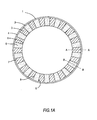
- reactor 1 has a cylindrical wall 2 and structured packing 3, depicted as a shaded area, resides within wall 1.
- the outside diameter 4 of packing 3 corresponds to the inside diameter of wall 1.
- Packing 3 has an inside diameter 5 and is divided into longitudinal columns 6 (depicted by shaded and dotted areas), and longitudinal columns 7 (depicted by shaded and cross-hatched areas). Columns 6 and 7 alternate with each other and are separated from each other by radial walls 8.
- Reactor 1 has intermittent gaps (not shown) disposed between radial walls 8 and reactor wall 2 along the axial length of the reactor. Fluid flowing along the length of reactor 1 is directed in a centrifugal direction through columns 6 and in a centripetal direction while flowing through columns 7.
- column 6 extends from its outside diameter 4 to its inside diameter 5.
- Column 6 is bounded at its outside diameter 4 by reactor wall 2.
- the axial length of column 6 contains vanes 9. Vanes 9 form channels 10 which direct fluid centrifugally as the fluid passes from the top to the bottom of reactor 1.
- centripetal column 7 extends from its outside diameter 4 to its inside diameter 5.
- Column 7 is bounded at its outside diameter 4 by reactor wall 2.
- the axial length of column 7 contains vanes 11. Vanes 11 form channels 12 which direct fluid centripetally as the fluid passes from the top to the bottom of reactor 1.
- sheet 20 is formed into a structured packing of the invention by cutting and bending columns 21 consisting of repeated shapes 30 forming centripetal vanes, and columns 22 consisting of repeated shapes 40 forming centrifugal vanes.
- Sheet 20 comprises a ductile, rigid material and is preferably metal foil.
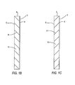
- Shape 30 is formed from sheet 20 into a vane and its two lateral webs which connect the vane to the sheet from which it is formed. Solid lines depict where the sheet is cut. Dotted lines depict approximately 90° bends in the sheet. Dashed lines depict approximately 180° bends in the sheet.
- Sheet 20 is cut along lines 31, 32 and 33, wherein horizontal line 33 corresponds to horizontal line 32 for the adjacent shape (not shown) that is similar to and below shape 30 that is shown.
- the sheet is folded approximately 90° away from the reader along lines 34 and folded approximately 180° toward the reader along lines 35.
- the thus-formed vane 9 consists of the essentially flat surface bounded by lines 32, 33 and 34. Vane 9 is attached to the rest of the sheet by webs 37 along the two sides of the vane. Webs 37 are bounded by lines 31, 34 and 35.
- vane 9 is preferably wider at its top rather than at its bottom as shown.
- Vane 9 is a vane creating centripetal channels for fluid flowing from the top to the bottom of reactor 1.
- vane 9 preferably has the same width at its top and bottom.
- Sheet 20 is cut along lines 41, 42 and 43, wherein horizontal line 43 corresponds to horizontal line 42 for the adjacent shape (not shown) that is similar to and below the shape 40 shown.
- Sheet 20 is folded approximately 90° toward the reader along lines 44 and folded approximately 180° away from the reader along line 45.
- the thus-formed vane 11 consists of the essentially flat surface bounded by lines 42, 43 and 44. Vane 11 is attached to the rest of the sheet by webs 47 along the two sides of the vane. Webs 47 are bounded by lines 41, 44 and 45.
- vane 11 is preferably narrower at its top than at its bottom as shown, and vane 11 creates centrifugal channels for fluid flowing from the top to the bottom of reactor 1.
- vane 47 preferably has the same width at its top and bottom.
- bottom shape 30 in columns 21 is disposed only partially above the lower edge 23 of sheet 20. Cut edges 31 and 32 for bottom shape 30 of column 21 may result in voids or the absence of packing for such bottom shapes.
- top shape 40 in columns 22 is disposed only partially below upper edge 24 of sheet 20. Upper shapes 40 are accordingly truncated by top edge 24.
- the sheet formed as described above is cut into lateral lengths and bent into a ring or annular shape or otherwise inserted near one or two reactor walls.
- the ends of rings may be joined by welding, adhesive or by interlocking the ends.
- FIG. 4 is a cutaway perspective view of the structured packing of the invention for a cylindrical or annular reactor in which all items in FIG. 4 corresponding to the previously-described figures has the same numbering as set forth in the previously-described figures.
- the reactor walls are not shown in FIG. 4 .
- Alternating separating walls 8 of the packing are respectively illustrated with different shading darkness from each other. Note that the vanes and webs are not shaded.
- Packing 3 arrives at an outside diameter at location 4 and at an inside diameter at location 5.
- Centrifugal vanes 9 attached to the separating walls by webs 37 occupy centrifugal columns of the packing.
- Centripetal vanes 11 attached to the separating walls by webs 37 occupy centripetal columns of the packing.
- the centrifugal and centripetal columns alternate with each other around the casing and extend along the entire length of reactor 1, preferably from the reactor inlet to the reactor outlet.
- multiple structured packing of the invention may be disposed in series within a single reactor between heat sources and heat sinks.
- two or more of the structured packing units could be placed concentrically and adjacent to each other in an annular or circular reactor.
- Two or more of the structured packing units could be placed adjacent and parallel to each other between two plate-shaped reactor walls or between two reactor walls of different geometry.
Landscapes
- Chemical & Material Sciences (AREA)
- Organic Chemistry (AREA)
- Chemical Kinetics & Catalysis (AREA)
- Physics & Mathematics (AREA)
- Thermal Sciences (AREA)
- Engineering & Computer Science (AREA)
- Materials Engineering (AREA)
- Physical Or Chemical Processes And Apparatus (AREA)
- Catalysts (AREA)
Priority Applications (1)
| Application Number | Priority Date | Filing Date | Title |
|---|---|---|---|
| PL10738911T PL2393589T3 (pl) | 2009-02-09 | 2010-01-19 | Wypełnienie strukturalne dla reaktora |
Applications Claiming Priority (3)
| Application Number | Priority Date | Filing Date | Title |
|---|---|---|---|
| US20717009P | 2009-02-09 | 2009-02-09 | |
| US12/688,948 US8235361B2 (en) | 2009-02-09 | 2010-01-18 | Structured packing for a reactor |
| PCT/US2010/021401 WO2010090817A2 (en) | 2009-02-09 | 2010-01-19 | Structured packing for a reactor |
Publications (3)
| Publication Number | Publication Date |
|---|---|
| EP2393589A2 EP2393589A2 (en) | 2011-12-14 |
| EP2393589A4 EP2393589A4 (en) | 2014-01-15 |
| EP2393589B1 true EP2393589B1 (en) | 2015-04-22 |
Family
ID=42540573
Family Applications (1)
| Application Number | Title | Priority Date | Filing Date |
|---|---|---|---|
| EP20100738911 Active EP2393589B1 (en) | 2009-02-09 | 2010-01-19 | Structured packing for a reactor |
Country Status (14)
| Country | Link |
|---|---|
| US (2) | US8235361B2 (pl) |
| EP (1) | EP2393589B1 (pl) |
| JP (1) | JP5456066B2 (pl) |
| KR (1) | KR101679232B1 (pl) |
| CN (1) | CN102271802A (pl) |
| CA (1) | CA2746466C (pl) |
| DK (1) | DK2393589T3 (pl) |
| ES (1) | ES2542235T3 (pl) |
| HU (1) | HUE025034T2 (pl) |
| MX (1) | MX2011007362A (pl) |
| PL (1) | PL2393589T3 (pl) |
| PT (1) | PT2393589E (pl) |
| RU (1) | RU2466788C1 (pl) |
| WO (1) | WO2010090817A2 (pl) |
Families Citing this family (13)
| Publication number | Priority date | Publication date | Assignee | Title |
|---|---|---|---|---|
| US8361432B2 (en) * | 2010-12-08 | 2013-01-29 | Fluor Enterprises, Inc. | Reactor, a retained catalyst structure, and a method for improving decomposition of polysulfides and removal of hydrogen sulfide in liquid sulfur |
| US8932536B2 (en) | 2011-05-10 | 2015-01-13 | Zoneflow Reactor Technologies, LLC | Reactor packing |
| JP6124990B2 (ja) * | 2013-02-28 | 2017-05-10 | 三菱電機株式会社 | 放熱構造及び光送受信器 |
| US20150071835A1 (en) * | 2013-09-09 | 2015-03-12 | Zoneflow Reactor Technologies, LLC | Non-adiabatic catalytic reactor |
| CN103752253B (zh) * | 2014-01-26 | 2017-01-04 | 中建安装工程有限公司 | 一种具有径向分布能力的催化精馏填料 |
| GB201403787D0 (en) | 2014-03-04 | 2014-04-16 | Johnson Matthey Plc | Steam reforming |
| GB201403788D0 (en) | 2014-03-04 | 2014-04-16 | Johnson Matthey Plc | Catalyst arrangement |
| CN107159085A (zh) * | 2017-05-27 | 2017-09-15 | 天津九源化工工程有限公司 | 一种用于传质塔的自分布规整填料及加工使用方法 |
| US11891302B2 (en) | 2020-03-17 | 2024-02-06 | Bayotech, Inc. | Hydrogen generation systems |
| US10894244B1 (en) | 2020-03-17 | 2021-01-19 | Bayotech, Inc. | Hydrogen generation systems |
| US11608266B2 (en) | 2020-03-17 | 2023-03-21 | Bayotech, Inc. | Hydrogen generation systems |
| GB202012614D0 (en) | 2020-08-13 | 2020-09-30 | Johnson Matthey Plc | Steam reforming |
| CN118925649B (zh) * | 2024-08-16 | 2025-09-09 | 中北大学 | 用于液-液沉淀反应的超重力旋转床用规整填料 |
Family Cites Families (17)
| Publication number | Priority date | Publication date | Assignee | Title |
|---|---|---|---|---|
| JPS5346474A (en) * | 1976-10-08 | 1978-04-26 | Matsushita Electric Ind Co Ltd | Catalytic cleaning apparatus for exhaust gas |
| EP0025308B1 (en) * | 1979-09-06 | 1984-07-11 | Imperial Chemical Industries Plc | A process and apparatus for catalytically reacting steam with a hydrocarbon in endothermic conditions |
| SU940817A1 (ru) * | 1980-11-04 | 1982-07-07 | Одесский ордена Трудового Красного Знамени политехнический институт | Насадка дл процессов тепломассообмена |
| SU971445A1 (ru) * | 1981-04-20 | 1982-11-07 | Московский Ордена Октябрьской Революции И Ордена Трудового Красного Знамени Институт Нефтехимической И Газовой Промышленности Им.И.М.Губкина | Насадка дл массообменных аппаратов |
| CH656320A5 (de) * | 1981-07-30 | 1986-06-30 | Sulzer Ag | Einbauelement fuer eine vorrichtung fuer stoff- und/oder direkten waermeaustausch oder mischen. |
| CH653566A5 (de) * | 1981-07-30 | 1986-01-15 | Sulzer Ag | Kolonne fuer stoff- und direkten waermeaustausch. |
| JPS6075303A (ja) * | 1983-06-21 | 1985-04-27 | グリツツ・インコ−ポレイテツド | 塔充填体 |
| JPS60179101A (ja) * | 1984-02-28 | 1985-09-13 | Ngk Insulators Ltd | 流体接触用多孔体 |
| DK156701C (da) * | 1987-08-27 | 1990-01-29 | Haldor Topsoe As | Fremgangsmaade til gennemfoerelse af heterogene katalytiske kemiske reaktioner |
| US4882130A (en) * | 1988-06-07 | 1989-11-21 | Ngk Insulators, Ltd. | Porous structure of fluid contact |
| RU2052284C1 (ru) * | 1993-08-06 | 1996-01-20 | Акционерное общество "Миннибаевский ГПЗ" | Насадка для абсорбционного аппарата |
| RU6347U1 (ru) * | 1996-02-20 | 1998-04-16 | Инженерно-внедренческий центр "Инжехим" | Насадка для ректификационных и абсорбционных колонн |
| BR0014779B1 (pt) * | 1999-10-15 | 2011-05-17 | equipamento para remoção de pelo menos um óxido de nitrogênio a partir de um fluido. | |
| US20040052703A1 (en) * | 2001-08-21 | 2004-03-18 | Catalytic Distillation Technologies | Contact structures |
| DE20117873U1 (de) * | 2001-11-06 | 2002-02-14 | Emitec Gesellschaft für Emissionstechnologie mbH, 53797 Lohmar | Offener Filterkörper mit verbesserten Strömungseigenschaften |
| DE10159818A1 (de) | 2001-12-06 | 2003-07-10 | Basf Ag | Geordnete Packung für einen Reaktor |
| RU2357793C2 (ru) | 2004-11-23 | 2009-06-10 | Джонатан Дж. ФЕЙНСТЕЙН | Реактор с теплообменом ударной струей |
-
2010
- 2010-01-18 US US12/688,948 patent/US8235361B2/en active Active
- 2010-01-19 CN CN2010800040155A patent/CN102271802A/zh active Pending
- 2010-01-19 RU RU2011127698/05A patent/RU2466788C1/ru not_active IP Right Cessation
- 2010-01-19 MX MX2011007362A patent/MX2011007362A/es active IP Right Grant
- 2010-01-19 EP EP20100738911 patent/EP2393589B1/en active Active
- 2010-01-19 PT PT107389116T patent/PT2393589E/pt unknown
- 2010-01-19 KR KR1020117017288A patent/KR101679232B1/ko active Active
- 2010-01-19 PL PL10738911T patent/PL2393589T3/pl unknown
- 2010-01-19 CA CA2746466A patent/CA2746466C/en active Active
- 2010-01-19 DK DK10738911.6T patent/DK2393589T3/en active
- 2010-01-19 WO PCT/US2010/021401 patent/WO2010090817A2/en not_active Ceased
- 2010-01-19 ES ES10738911.6T patent/ES2542235T3/es active Active
- 2010-01-19 HU HUE10738911A patent/HUE025034T2/en unknown
- 2010-01-19 JP JP2011549172A patent/JP5456066B2/ja active Active
-
2012
- 2012-08-03 US US13/566,108 patent/US20120294779A1/en not_active Abandoned
Also Published As
| Publication number | Publication date |
|---|---|
| RU2466788C1 (ru) | 2012-11-20 |
| US8235361B2 (en) | 2012-08-07 |
| US20120294779A1 (en) | 2012-11-22 |
| JP5456066B2 (ja) | 2014-03-26 |
| PT2393589E (pt) | 2015-08-28 |
| KR101679232B1 (ko) | 2016-12-06 |
| DK2393589T3 (en) | 2015-07-20 |
| EP2393589A4 (en) | 2014-01-15 |
| HUE025034T2 (en) | 2016-01-28 |
| WO2010090817A3 (en) | 2010-10-28 |
| EP2393589A2 (en) | 2011-12-14 |
| KR20110137284A (ko) | 2011-12-22 |
| US20100202942A1 (en) | 2010-08-12 |
| CA2746466C (en) | 2013-12-24 |
| ES2542235T3 (es) | 2015-08-03 |
| MX2011007362A (es) | 2011-12-14 |
| WO2010090817A2 (en) | 2010-08-12 |
| PL2393589T3 (pl) | 2015-09-30 |
| CA2746466A1 (en) | 2010-08-12 |
| JP2012517338A (ja) | 2012-08-02 |
| CN102271802A (zh) | 2011-12-07 |
Similar Documents
| Publication | Publication Date | Title |
|---|---|---|
| EP2393589B1 (en) | Structured packing for a reactor | |
| CN103402617B (zh) | 改进的可堆叠结构反应器 | |
| JP4745444B2 (ja) | ランダム充填要素及びこれを含むカラム | |
| CN100509132C (zh) | 催化床反应器用板式热交换器 | |
| AU760912B2 (en) | Filler body with a cross channel structure | |
| US7749467B2 (en) | Optimizer hydraulic enhancement using milled plate | |
| JP2010175245A (ja) | 多目的マイクロチャネルマイクロコンポーネント | |
| EP2607831A1 (en) | A heat exchanger | |
| EP1992406B1 (en) | Louver front faced inlet ducts | |
| WO2009109379A1 (en) | Catalytic reactor | |
| KR100966844B1 (ko) | 제트 충돌 열전달 반응기 | |
| GB2103953A (en) | Catalyst devices | |
| JP2021105507A (ja) | フローリアクター | |
| WO2015048013A1 (en) | Heat exchanger | |
| EP3471872B1 (en) | Scallop support distributor for radial flow reactor | |
| US12179167B2 (en) | Structured packing for gas phase reactor | |
| CA2950383C (en) | Systems and methods for constructing engineered packing for heat exchange |
Legal Events
| Date | Code | Title | Description |
|---|---|---|---|
| PUAI | Public reference made under article 153(3) epc to a published international application that has entered the european phase |
Free format text: ORIGINAL CODE: 0009012 |
|
| 17P | Request for examination filed |
Effective date: 20110609 |
|
| AK | Designated contracting states |
Kind code of ref document: A2 Designated state(s): AT BE BG CH CY CZ DE DK EE ES FI FR GB GR HR HU IE IS IT LI LT LU LV MC MK MT NL NO PL PT RO SE SI SK SM TR |
|
| DAX | Request for extension of the european patent (deleted) | ||
| A4 | Supplementary search report drawn up and despatched |
Effective date: 20131217 |
|
| RIC1 | Information provided on ipc code assigned before grant |
Ipc: B01J 19/32 20060101AFI20131211BHEP Ipc: B01J 8/02 20060101ALI20131211BHEP |
|
| GRAJ | Information related to disapproval of communication of intention to grant by the applicant or resumption of examination proceedings by the epo deleted |
Free format text: ORIGINAL CODE: EPIDOSDIGR1 |
|
| GRAP | Despatch of communication of intention to grant a patent |
Free format text: ORIGINAL CODE: EPIDOSNIGR1 |
|
| GRAP | Despatch of communication of intention to grant a patent |
Free format text: ORIGINAL CODE: EPIDOSNIGR1 |
|
| INTG | Intention to grant announced |
Effective date: 20150123 |
|
| RAP1 | Party data changed (applicant data changed or rights of an application transferred) |
Owner name: TRIBUTE CREATIONS, LLC |
|
| GRAS | Grant fee paid |
Free format text: ORIGINAL CODE: EPIDOSNIGR3 |
|
| GRAA | (expected) grant |
Free format text: ORIGINAL CODE: 0009210 |
|
| AK | Designated contracting states |
Kind code of ref document: B1 Designated state(s): AT BE BG CH CY CZ DE DK EE ES FI FR GB GR HR HU IE IS IT LI LT LU LV MC MK MT NL NO PL PT RO SE SI SK SM TR |
|
| REG | Reference to a national code |
Ref country code: GB Ref legal event code: FG4D |
|
| RIN1 | Information on inventor provided before grant (corrected) |
Inventor name: FEINSTEIN, JONATHAN JAY |
|
| REG | Reference to a national code |
Ref country code: CH Ref legal event code: EP |
|
| REG | Reference to a national code |
Ref country code: AT Ref legal event code: REF Ref document number: 722881 Country of ref document: AT Kind code of ref document: T Effective date: 20150515 |
|
| REG | Reference to a national code |
Ref country code: IE Ref legal event code: FG4D |
|
| REG | Reference to a national code |
Ref country code: DE Ref legal event code: R096 Ref document number: 602010024134 Country of ref document: DE Effective date: 20150603 |
|
| RAP2 | Party data changed (patent owner data changed or rights of a patent transferred) |
Owner name: ZONEFLOW REACTOR TECHNOLOGIES, LLC |
|
| REG | Reference to a national code |
Ref country code: DE Ref legal event code: R082 Ref document number: 602010024134 Country of ref document: DE Representative=s name: LEMCKE, BROMMER & PARTNER, PATENTANWAELTE PART, DE Ref country code: DE Ref legal event code: R081 Ref document number: 602010024134 Country of ref document: DE Owner name: ZONEFLOW REACTOR TECHNOLOGIES, LLC, WINDSOR, US Free format text: FORMER OWNER: TRIBUTE CREATIONS, LLC, WINDSOR LOCKS, CONN., US |
|
| REG | Reference to a national code |
Ref country code: NL Ref legal event code: T3 |
|
| RAP2 | Party data changed (patent owner data changed or rights of a patent transferred) |
Owner name: ZONEFLOW REACTOR TECHNOLOGIES, LLC |
|
| REG | Reference to a national code |
Ref country code: DK Ref legal event code: T3 Effective date: 20150714 |
|
| REG | Reference to a national code |
Ref country code: SE Ref legal event code: TRGR |
|
| REG | Reference to a national code |
Ref country code: NO Ref legal event code: T2 Effective date: 20150422 Ref country code: ES Ref legal event code: FG2A Ref document number: 2542235 Country of ref document: ES Kind code of ref document: T3 Effective date: 20150803 |
|
| REG | Reference to a national code |
Ref country code: NL Ref legal event code: TD Effective date: 20150812 |
|
| REG | Reference to a national code |
Ref country code: PT Ref legal event code: SC4A Free format text: AVAILABILITY OF NATIONAL TRANSLATION Effective date: 20150709 |
|
| REG | Reference to a national code |
Ref country code: LT Ref legal event code: MG4D |
|
| REG | Reference to a national code |
Ref country code: PL Ref legal event code: T3 |
|
| REG | Reference to a national code |
Ref country code: AT Ref legal event code: HC Ref document number: 722881 Country of ref document: AT Kind code of ref document: T Owner name: ZONEFLOW REACTOR TECHNOLOGIES, LLC, US Effective date: 20150902 |
|
| PG25 | Lapsed in a contracting state [announced via postgrant information from national office to epo] |
Ref country code: HR Free format text: LAPSE BECAUSE OF FAILURE TO SUBMIT A TRANSLATION OF THE DESCRIPTION OR TO PAY THE FEE WITHIN THE PRESCRIBED TIME-LIMIT Effective date: 20150422 Ref country code: LT Free format text: LAPSE BECAUSE OF FAILURE TO SUBMIT A TRANSLATION OF THE DESCRIPTION OR TO PAY THE FEE WITHIN THE PRESCRIBED TIME-LIMIT Effective date: 20150422 |
|
| REG | Reference to a national code |
Ref country code: GR Ref legal event code: EP Ref document number: 20150401384 Country of ref document: GR Effective date: 20150901 |
|
| PG25 | Lapsed in a contracting state [announced via postgrant information from national office to epo] |
Ref country code: IS Free format text: LAPSE BECAUSE OF FAILURE TO SUBMIT A TRANSLATION OF THE DESCRIPTION OR TO PAY THE FEE WITHIN THE PRESCRIBED TIME-LIMIT Effective date: 20150822 Ref country code: LV Free format text: LAPSE BECAUSE OF FAILURE TO SUBMIT A TRANSLATION OF THE DESCRIPTION OR TO PAY THE FEE WITHIN THE PRESCRIBED TIME-LIMIT Effective date: 20150422 |
|
| REG | Reference to a national code |
Ref country code: FR Ref legal event code: PLFP Year of fee payment: 7 |
|
| REG | Reference to a national code |
Ref country code: DE Ref legal event code: R097 Ref document number: 602010024134 Country of ref document: DE |
|
| REG | Reference to a national code |
Ref country code: HU Ref legal event code: AG4A Ref document number: E025034 Country of ref document: HU |
|
| PG25 | Lapsed in a contracting state [announced via postgrant information from national office to epo] |
Ref country code: EE Free format text: LAPSE BECAUSE OF FAILURE TO SUBMIT A TRANSLATION OF THE DESCRIPTION OR TO PAY THE FEE WITHIN THE PRESCRIBED TIME-LIMIT Effective date: 20150422 |
|
| REG | Reference to a national code |
Ref country code: SK Ref legal event code: T3 Ref document number: E 19442 Country of ref document: SK |
|
| PLBE | No opposition filed within time limit |
Free format text: ORIGINAL CODE: 0009261 |
|
| STAA | Information on the status of an ep patent application or granted ep patent |
Free format text: STATUS: NO OPPOSITION FILED WITHIN TIME LIMIT |
|
| PG25 | Lapsed in a contracting state [announced via postgrant information from national office to epo] |
Ref country code: RO Free format text: LAPSE BECAUSE OF NON-PAYMENT OF DUE FEES Effective date: 20150422 |
|
| 26N | No opposition filed |
Effective date: 20160125 |
|
| PGFP | Annual fee paid to national office [announced via postgrant information from national office to epo] |
Ref country code: DK Payment date: 20160122 Year of fee payment: 7 Ref country code: TR Payment date: 20160114 Year of fee payment: 7 Ref country code: CZ Payment date: 20160113 Year of fee payment: 7 Ref country code: NO Payment date: 20160121 Year of fee payment: 7 Ref country code: BG Payment date: 20160120 Year of fee payment: 7 Ref country code: SK Payment date: 20160113 Year of fee payment: 7 |
|
| PG25 | Lapsed in a contracting state [announced via postgrant information from national office to epo] |
Ref country code: SI Free format text: LAPSE BECAUSE OF FAILURE TO SUBMIT A TRANSLATION OF THE DESCRIPTION OR TO PAY THE FEE WITHIN THE PRESCRIBED TIME-LIMIT Effective date: 20150422 |
|
| PGFP | Annual fee paid to national office [announced via postgrant information from national office to epo] |
Ref country code: GR Payment date: 20160121 Year of fee payment: 7 Ref country code: BE Payment date: 20160121 Year of fee payment: 7 Ref country code: PT Payment date: 20160118 Year of fee payment: 7 Ref country code: PL Payment date: 20160114 Year of fee payment: 7 Ref country code: SE Payment date: 20160121 Year of fee payment: 7 Ref country code: FI Payment date: 20160120 Year of fee payment: 7 Ref country code: AT Payment date: 20160120 Year of fee payment: 7 Ref country code: HU Payment date: 20160114 Year of fee payment: 7 |
|
| PG25 | Lapsed in a contracting state [announced via postgrant information from national office to epo] |
Ref country code: LU Free format text: LAPSE BECAUSE OF FAILURE TO SUBMIT A TRANSLATION OF THE DESCRIPTION OR TO PAY THE FEE WITHIN THE PRESCRIBED TIME-LIMIT Effective date: 20160119 |
|
| REG | Reference to a national code |
Ref country code: CH Ref legal event code: PL |
|
| PG25 | Lapsed in a contracting state [announced via postgrant information from national office to epo] |
Ref country code: MC Free format text: LAPSE BECAUSE OF FAILURE TO SUBMIT A TRANSLATION OF THE DESCRIPTION OR TO PAY THE FEE WITHIN THE PRESCRIBED TIME-LIMIT Effective date: 20150422 |
|
| PG25 | Lapsed in a contracting state [announced via postgrant information from national office to epo] |
Ref country code: CH Free format text: LAPSE BECAUSE OF NON-PAYMENT OF DUE FEES Effective date: 20160131 Ref country code: LI Free format text: LAPSE BECAUSE OF NON-PAYMENT OF DUE FEES Effective date: 20160131 |
|
| REG | Reference to a national code |
Ref country code: IE Ref legal event code: MM4A |
|
| REG | Reference to a national code |
Ref country code: FR Ref legal event code: PLFP Year of fee payment: 8 |
|
| PG25 | Lapsed in a contracting state [announced via postgrant information from national office to epo] |
Ref country code: IE Free format text: LAPSE BECAUSE OF NON-PAYMENT OF DUE FEES Effective date: 20160119 |
|
| REG | Reference to a national code |
Ref country code: AT Ref legal event code: UEP Ref document number: 722881 Country of ref document: AT Kind code of ref document: T Effective date: 20150422 |
|
| PG25 | Lapsed in a contracting state [announced via postgrant information from national office to epo] |
Ref country code: BE Free format text: LAPSE BECAUSE OF NON-PAYMENT OF DUE FEES Effective date: 20170131 |
|
| REG | Reference to a national code |
Ref country code: DK Ref legal event code: EBP Effective date: 20170131 |
|
| REG | Reference to a national code |
Ref country code: NO Ref legal event code: MMEP |
|
| PG25 | Lapsed in a contracting state [announced via postgrant information from national office to epo] |
Ref country code: MT Free format text: LAPSE BECAUSE OF FAILURE TO SUBMIT A TRANSLATION OF THE DESCRIPTION OR TO PAY THE FEE WITHIN THE PRESCRIBED TIME-LIMIT Effective date: 20150422 |
|
| REG | Reference to a national code |
Ref country code: AT Ref legal event code: MM01 Ref document number: 722881 Country of ref document: AT Kind code of ref document: T Effective date: 20170119 |
|
| REG | Reference to a national code |
Ref country code: SK Ref legal event code: MM4A Ref document number: E 19442 Country of ref document: SK Effective date: 20170119 |
|
| PG25 | Lapsed in a contracting state [announced via postgrant information from national office to epo] |
Ref country code: NO Free format text: LAPSE BECAUSE OF NON-PAYMENT OF DUE FEES Effective date: 20170131 Ref country code: GR Free format text: LAPSE BECAUSE OF NON-PAYMENT OF DUE FEES Effective date: 20170811 Ref country code: CZ Free format text: LAPSE BECAUSE OF NON-PAYMENT OF DUE FEES Effective date: 20170119 Ref country code: AT Free format text: LAPSE BECAUSE OF NON-PAYMENT OF DUE FEES Effective date: 20170119 Ref country code: SK Free format text: LAPSE BECAUSE OF NON-PAYMENT OF DUE FEES Effective date: 20170119 Ref country code: FI Free format text: LAPSE BECAUSE OF NON-PAYMENT OF DUE FEES Effective date: 20170119 |
|
| PG25 | Lapsed in a contracting state [announced via postgrant information from national office to epo] |
Ref country code: SE Free format text: LAPSE BECAUSE OF NON-PAYMENT OF DUE FEES Effective date: 20170120 Ref country code: PT Free format text: LAPSE BECAUSE OF NON-PAYMENT OF DUE FEES Effective date: 20170719 Ref country code: HU Free format text: LAPSE BECAUSE OF NON-PAYMENT OF DUE FEES Effective date: 20170120 |
|
| REG | Reference to a national code |
Ref country code: FR Ref legal event code: PLFP Year of fee payment: 9 |
|
| PG25 | Lapsed in a contracting state [announced via postgrant information from national office to epo] |
Ref country code: DK Free format text: LAPSE BECAUSE OF NON-PAYMENT OF DUE FEES Effective date: 20170131 |
|
| REG | Reference to a national code |
Ref country code: BE Ref legal event code: FP Effective date: 20150619 Ref country code: BE Ref legal event code: HC Owner name: ZONEFLOW REACTOR TECHNOLOGIES, LLC; US Free format text: DETAILS ASSIGNMENT: CHANGE OF OWNER(S), CHANGEMENT NOM PROPRIETAIRE, NOM + CODE POSTAL; FORMER OWNER NAME: TRIBUTE CREATIONS, LLC Effective date: 20150619 Ref country code: BE Ref legal event code: MM Effective date: 20170131 |
|
| PG25 | Lapsed in a contracting state [announced via postgrant information from national office to epo] |
Ref country code: CY Free format text: LAPSE BECAUSE OF FAILURE TO SUBMIT A TRANSLATION OF THE DESCRIPTION OR TO PAY THE FEE WITHIN THE PRESCRIBED TIME-LIMIT Effective date: 20150422 Ref country code: SM Free format text: LAPSE BECAUSE OF FAILURE TO SUBMIT A TRANSLATION OF THE DESCRIPTION OR TO PAY THE FEE WITHIN THE PRESCRIBED TIME-LIMIT Effective date: 20150422 |
|
| PG25 | Lapsed in a contracting state [announced via postgrant information from national office to epo] |
Ref country code: MT Free format text: LAPSE BECAUSE OF FAILURE TO SUBMIT A TRANSLATION OF THE DESCRIPTION OR TO PAY THE FEE WITHIN THE PRESCRIBED TIME-LIMIT Effective date: 20160131 Ref country code: MK Free format text: LAPSE BECAUSE OF FAILURE TO SUBMIT A TRANSLATION OF THE DESCRIPTION OR TO PAY THE FEE WITHIN THE PRESCRIBED TIME-LIMIT Effective date: 20150422 |
|
| PG25 | Lapsed in a contracting state [announced via postgrant information from national office to epo] |
Ref country code: PL Free format text: LAPSE BECAUSE OF NON-PAYMENT OF DUE FEES Effective date: 20170119 |
|
| PG25 | Lapsed in a contracting state [announced via postgrant information from national office to epo] |
Ref country code: BG Free format text: LAPSE BECAUSE OF NON-PAYMENT OF DUE FEES Effective date: 20170808 |
|
| PG25 | Lapsed in a contracting state [announced via postgrant information from national office to epo] |
Ref country code: TR Free format text: LAPSE BECAUSE OF NON-PAYMENT OF DUE FEES Effective date: 20170119 |
|
| P01 | Opt-out of the competence of the unified patent court (upc) registered |
Effective date: 20230524 |
|
| PGFP | Annual fee paid to national office [announced via postgrant information from national office to epo] |
Ref country code: NL Payment date: 20250122 Year of fee payment: 16 |
|
| PGFP | Annual fee paid to national office [announced via postgrant information from national office to epo] |
Ref country code: DE Payment date: 20241220 Year of fee payment: 16 |
|
| PGFP | Annual fee paid to national office [announced via postgrant information from national office to epo] |
Ref country code: ES Payment date: 20250214 Year of fee payment: 16 |
|
| PGFP | Annual fee paid to national office [announced via postgrant information from national office to epo] |
Ref country code: FR Payment date: 20250123 Year of fee payment: 16 |
|
| PGFP | Annual fee paid to national office [announced via postgrant information from national office to epo] |
Ref country code: IT Payment date: 20250131 Year of fee payment: 16 Ref country code: GB Payment date: 20250123 Year of fee payment: 16 |