EP2607831A1 - A heat exchanger - Google Patents
A heat exchanger Download PDFInfo
- Publication number
- EP2607831A1 EP2607831A1 EP12192753.7A EP12192753A EP2607831A1 EP 2607831 A1 EP2607831 A1 EP 2607831A1 EP 12192753 A EP12192753 A EP 12192753A EP 2607831 A1 EP2607831 A1 EP 2607831A1
- Authority
- EP
- European Patent Office
- Prior art keywords
- heat exchanger
- ridges
- plate
- corrugations
- main
- Prior art date
- Legal status (The legal status is an assumption and is not a legal conclusion. Google has not performed a legal analysis and makes no representation as to the accuracy of the status listed.)
- Withdrawn
Links
Images


Classifications
-
- F—MECHANICAL ENGINEERING; LIGHTING; HEATING; WEAPONS; BLASTING
- F28—HEAT EXCHANGE IN GENERAL
- F28F—DETAILS OF HEAT-EXCHANGE AND HEAT-TRANSFER APPARATUS, OF GENERAL APPLICATION
- F28F3/00—Plate-like or laminated elements; Assemblies of plate-like or laminated elements
- F28F3/005—Arrangements for preventing direct contact between different heat-exchange media
-
- F—MECHANICAL ENGINEERING; LIGHTING; HEATING; WEAPONS; BLASTING
- F28—HEAT EXCHANGE IN GENERAL
- F28F—DETAILS OF HEAT-EXCHANGE AND HEAT-TRANSFER APPARATUS, OF GENERAL APPLICATION
- F28F3/00—Plate-like or laminated elements; Assemblies of plate-like or laminated elements
- F28F3/02—Elements or assemblies thereof with means for increasing heat-transfer area, e.g. with fins, with recesses, with corrugations
- F28F3/04—Elements or assemblies thereof with means for increasing heat-transfer area, e.g. with fins, with recesses, with corrugations the means being integral with the element
- F28F3/042—Elements or assemblies thereof with means for increasing heat-transfer area, e.g. with fins, with recesses, with corrugations the means being integral with the element in the form of local deformations of the element
- F28F3/046—Elements or assemblies thereof with means for increasing heat-transfer area, e.g. with fins, with recesses, with corrugations the means being integral with the element in the form of local deformations of the element the deformations being linear, e.g. corrugations
-
- F—MECHANICAL ENGINEERING; LIGHTING; HEATING; WEAPONS; BLASTING
- F28—HEAT EXCHANGE IN GENERAL
- F28D—HEAT-EXCHANGE APPARATUS, NOT PROVIDED FOR IN ANOTHER SUBCLASS, IN WHICH THE HEAT-EXCHANGE MEDIA DO NOT COME INTO DIRECT CONTACT
- F28D9/00—Heat-exchange apparatus having stationary plate-like or laminated conduit assemblies for both heat-exchange media, the media being in contact with different sides of a conduit wall
- F28D9/0031—Heat-exchange apparatus having stationary plate-like or laminated conduit assemblies for both heat-exchange media, the media being in contact with different sides of a conduit wall the conduits for one heat-exchange medium being formed by paired plates touching each other
- F28D9/0037—Heat-exchange apparatus having stationary plate-like or laminated conduit assemblies for both heat-exchange media, the media being in contact with different sides of a conduit wall the conduits for one heat-exchange medium being formed by paired plates touching each other the conduits for the other heat-exchange medium also being formed by paired plates touching each other
-
- F—MECHANICAL ENGINEERING; LIGHTING; HEATING; WEAPONS; BLASTING
- F28—HEAT EXCHANGE IN GENERAL
- F28F—DETAILS OF HEAT-EXCHANGE AND HEAT-TRANSFER APPARATUS, OF GENERAL APPLICATION
- F28F2250/00—Arrangements for modifying the flow of the heat exchange media, e.g. flow guiding means; Particular flow patterns
- F28F2250/10—Particular pattern of flow of the heat exchange media
- F28F2250/106—Particular pattern of flow of the heat exchange media with cross flow
Definitions
- This invention relates to heat exchangers.
- the invention relates to cross-corrugated heat exchangers.
- heat exchangers to transfer the thermal energy from a hot fluid to a cold fluid is well known and finds application in many different industries.
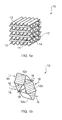
- One type of heat exchanger having good thermal and pneumatic performance is a cross-corrugated plate heat exchanger 10 as shown in Figure 1 .
- the cross corrugated plate heat exchanger 10 shown in Figure 1 includes a number of corrugated plates 12 which are stacked on top of one another such that the channels formed 14 by the corrugations lie at an angle to one another (90 degrees in this case).
- the plates are joined together by any suitable application led manufacturing technique such as brazing or welding.
- the material will also be application led but will typically be aluminium or other metal with a high thermal conductivity.
- the ends of the plates 12 are connected to manifolds such that hot and cold air or other fluids can be supplied in use and complex flow patterns induced between the plates 12.
- the complex flow patterns aid the heat transfer between the hot and cold air flows but at a penalty of increasing the pressure loss across the plates or a reduction in velocity and mass flow for a given pressure differential.
- Figure 1b shows a portion of the heat exchanger of Figure 1a in more detail.
- a lower plate 12a, mid plate 12b and upper plate 12c having corrugations which are orthogonal to the adjacent plate.
- Cold 16 and hot 18 air flows are passed through the channels formed by the corrugations as denoted by the dashed and solid lines respectively.
- These airflows 16, 18 result in a heat transfer from the hot flow 18 to the cold flow 16.
- the heat exchanger 10 is shown in Figure 1b as having crossed hot 18 and cold 16 flows in each layer.
- the matrix can be configured to have parallel-, cross- or contra-flows as desired.
- EP0403353 describes a heat exchanger formed from superimposed corrugated plates separating the fluid channels.
- the plates have alternate long and short facets which are oriented in opposite direction on adjacent plates. This is described as ensuring an optimum fluid flow along the plates and a reduction in friction.
- US4420039 describes a heat exchanger having a corrugated core structure with corrugated plates.
- the walls of the corrugations are provided with pairs of projections and recesses along their length which are successively separated by smooth wall portions. This is described as having the effect of successive throttling of the heat-transfer agent flow.
- US5806584 describes a heat exchanger composed of corrugated plates, the facets of which are provided with bosses and hollows in order to reduce pressure drops.
- EP1933105 describes a heat exchanger plate for the use in a plate heat exchanger having a first contact side and a second contact side, each comprising a pattern which provides respective uneven surfaces respective contact points for contacting a corresponding heat exchanger plate within a heat exchanger.
- the patterns are made up from a series of dents, indents, recesses, protrusions and/or additional corrugations between or outside the contact points.
- Cross-corrugated plate heat exchangers have high potential for meeting the requirements of the gas turbine engines and the present invention seeks to provide an improved heat exchanger which is suitable for aero applications amongst others.
- the present invention provides a heat exchanger, comprising: a plurality of stacked corrugated plates, each plate having a plurality of parallel main corrugations each having longitudinal peak ridges and trough ridges, wherein either or both of the peak ridges and trough ridges have an undulating profile so as to define a plurality of summits in a common plane.
- Either or both of the main corrugations and undulations may be periodic.
- the main corrugations and undulations will be substantially sinusoidal.
- the pitch of the undulations may be equal to the pitch of the main corrugations in an adjacent plate.
- the longitudinal axes of the main corrugations of adjacent plates may be angled relative to each other.
- the angle may be 90 degrees.
- the angle may be substantially 0 degrees or any angle between 0 and 180 degrees.
- the depth between adjacent ridges may be greater than the depth of the undulations.
- One or more of the summits may provide a seat portion for abutting a corresponding summit of an adjacent plate.
- the undulations of adjacent peak ridges and trough ridges in a plate may be in phase relative to the longitudinal axis of the main corrugations.
- each plate may have undulating ridges.
- At least one of the corrugated plates may include straight ridges.
- the main corrugations may be asymmetric.
- the main corrugations may have a saw toothed profile.
- the main corrugations may be tortuous along the longitudinal axis of the main corrugation.
- Corrugated plate heat exchanger matrices typically have high thermal transfer coefficients and good pneumatic performance.
- conventional corrugated plate matrices have non-uniform heat transfer coefficients across the surface of each corrugated plate, with, for example, a lower heat transfer coefficient in a trough of the corrugations.
- This non-uniformity in heat transfer results in a non-uniform temperature distribution in the heat exchanger plates and a reduction in performance as a consequence.
- a typical figure for this reduction in performance can be as high as 7%, which is unnecessarily high.
- the non-uniformity of heat transfer can lead to local thermal stresses in the heat exchanger matrix which are generally undesirable.
- a further consideration of heat exchangers for aero-engines is the minimum flow cross-section area dimension through the matrix. Typically, it can be necessary for 1mm diameter particles to be able to pass through an aero engine heat exchanger so that a given performance can be expected and blockages avoided. Nevertheless, it would be advantageous for larger particles to be able to pass through to help improve performance and reduce blockages further.
- one aim of the invention is to help increase the minimum flow dimension within the flow channels of the heat exchanger to allow for a greater particle size to pass through, without increasing the overall size of the heat exchanger matrix.
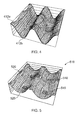
- FIG 2 shows a portion of a corrugated plate 210 according to the present invention.
- the plate 210 would be stacked with a plurality of similar corrugated plates to provide a heat exchanger matrix similar to that shown in Figure 1 .
- the corrugated plate 210 includes a plurality of parallel longitudinal main corrugations defined by peak ridges 212a and trough ridges 212b extending substantially the length of the plate 210 (of which only a portion is shown for the sake of clarity).
- the semi-enclosed space defined by each main corrugation can be thought of as a channel 218 through which an air flow passes in use.
- Each of the peak ridges 212a and trough ridges 212b have an undulating profile 216 so as to define a plurality of summits 220 on the upper 222 and lower 224 surfaces of the plate 210 as shown in Figure 2 .
- the summits 220 are provided in a common plane and have a pitch 226 which matches the pitch 228 of the ridges of an adjacent corrugated plate.
- each summit 220 provides a seat portion which is abutted and attached to a corresponding summit 220 of an adjacent plate, as can be seen in Figure 3a , where two plates 210a and 210b are stacked in a crossed arrangement (in this case at 90 degrees to one another).
- the profile of the undulations 216 and peaks and troughs of the main corrugation in the described embodiment are periodic, specifically sinusoidal, and extend across the majority of the plate.
- the undulations and main corrugation includes a pitch 226, 228 and amplitude 230, 232 which is uniform across the plate 210.
- the maximum possible amplitude of the undulations 216 is the amplitude of the corrugations.
- main corrugation and undulations of the embodiment are sinusoidal, it will be appreciated that other shapes of corrugations may be used. For example, rounded triangular or saw tooth profiles. Further, they may be out of phase.
- the plates 210 may be made from any suitable material as dictated by a particular application. Typically, the plates will be made from aluminium, stainless steel, titanium or nickel alloy for an aero application and would be provided with inlet and outlet manifolds and housings or casings in similar materials.
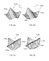
- Figure 3a shows an end view of an upper plate 210a and lower plate 210b having sinusoidal corrugations and undulations, respectively, which have corresponding pitches such that the summits 220 of the adjacent plates 210a, 210b are joined together to provide a unitary structure.
- the dip 234 of the undulation in the lower plate 210b is aligned with the dip 236 of the upper plate 210a undulation. This keeps the maximum height of the airflow path defined by the two plates more or less the same as would be the case if there were no undulations (as shown in Figure 3b ).
- the undulating upper ridge 212a increases in height to a summit 238 which vertically opposes the summit (not shown) of the lower plate 210b.
- the airflow path between the plates is a meandering, sinuous path which naturally churns up the airflow, as indicated by arrows 240 in Figure 2 .
- the churning results in a more energetic flow and greater heat transfer between the air flows and plates.
- the minimum flow area is increased with respect to prior art cross-corrugated arrangements 242 as shown in Figure 3b , which means that the spherical particle size which can pass along the airflow paths is larger. This can help reduce the likelihood of blocking.
- Typical values of pitch and amplitude for the main corrugations and undulations will be just a few millimetres.
- the geometry of the corrugations and undulations both have 3.3 mm pitch and the corrugations have 1.5 mm amplitude and the undulations have 0.5 mm amplitude, with a 90 degrees angle between the ridges of the corrugations on adjacent plates.
- the amplitudes may be in the range between 1mm and 5mm, and the pitch may be between 0.5 to 5 times the amplitude.
- One preferable range is a pitch which is between 2 and 4.5 times the amplitude.
- multiple plates are placed in a stacked arrangement and the corresponding summits of adjacent plates attached to each other so as to form a heat exchanger matrix in a similar manner to that shown in Figure 1 but with the undulating corrugated plates.
- the matrix may be connected to hot and cold airflows via a manifold which is configured to provide cross-, parallel- or contra-flowing streams of air.
- any suitable method of attachment may be used, for example, brazing or welding.
- the joining of adjacent plates is aided by providing each of the summits 520 of a plate 510 with a seat portion in the form of a flat area 546 which is configured to abut another corresponding seat portion of an adjacent plate.
- the seat portions provide an increased area of surface contact which helps increase the strength of the mechanical connection between adjacent plates. It will be appreciated that the seat portions may advantageously include surface features or roughness which aids the attachment of the corresponding seat portion.
- the individual plates may be stamped or electroformed and then brazed together.
- the summits may be prepared with a preferential application of braze on each of the seat portions as is known in the art.
- Figures 6a and 6b respectively show comparative plots 610a, 610b of the velocity magnitude normal to the surface (i.e. Vy) for a prior art corrugated plate 612a and a plate 612b according to the present invention. It can be seen from this plot that the effect of the undulations is to create increased velocity flows 648 near to the surface of the plate 612b which increases the thermal transfer between the airflows and the plates.
- FIGS 7a and 7b show Nusselt number distributions 710a, 710b on the bottom plate of a heat exchanger unit cell for a prior art plate 712a and a plate according to the present invention 712b.
- the largest Nusselt number occurs at the joining point of the peak ridge for both cases.
- the variation of Nusselt number from peak to trough is given in Figures 7a and 7b which show Nusselt number distributions 710a, 710b on the bottom plate of a heat exchanger unit cell for a prior art plate 712a and a plate according to the present invention 712b.
- the largest Nusselt number occurs at the joining point of the peak ridge for both cases.
- the present invention it is observed that the variation of Nusselt number from peak to trough
- volume goodness factor referred to is that defined as the Stanton number divided by the one third root of the fanning friction factor and is inversely proportional to matrix volume.
- area goodness factor is the Colburn j factor divided by the fanning friction factor and is inversely proportional to the frontal area of a heat exchanger matrix.
- Adjacent plates in the matrix may be angled relative to each other by a given angle of intersection.
- angle of intersection it is meant the angle between the longitudinal axes of the corrugations as shown in the graphical representation in Figure 8 in which the dotted lines represent the peak 810a and trough 812a ridges of the main corrugations of a first plate, and the peak 810b and trough 812b ridges of the main corrugations of a second plate, which are separated by an angle of intersection 814.
- angle of intersection it will be appreciated that the direction of airflow for the arrangement shown in Figure 8 relative to the angle of intersection is from left to right.
- the stacked heat exchanger plates described in embodiments above are arranged with intersection angles of 90 degrees.
- FIG 8 if the main corrugation peaks and troughs of an upper plate and the main corrugation peaks and troughs of a lower plate are skewed or rotated relative to each other by some angle, it is possible to get cross-flow arrangement of various intersection angles.
- H is the height of corrugation
- P the pitch of main corrugation
- P h the pitch of the undulation
- a h is a dimensionless undulation amplitude (zero to unity)
- ⁇ is the complementary angle of the intersection angle from 90 degrees.
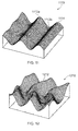
- Figure 9 shows plan and isometric views of unit cells of two stacked cross-corrugated heat exchanger plates 910a-d,912a-d, for various skew angles in which the plates have intersection angles of 90 degrees - Figure 9a , 60 degrees - Figure 9b , 45 degrees - Figure 9c and 30 degrees - Figure 9d .
- P/H 2.2
- Ph/H 2.2
- a h 0.2. If the hot side of heat exchanger plate in an orthogonal cross-flow matrix has a given angle of intersection, the angle of intersection for the cold side is the supplementary angle, and unless both angles are 90 degrees, the heat transfer and pressure loss characteristics of each side become different.
- the angle of intersection it is possible to separately control the heat exchanger performances of the hot and cold sides in order to optimise a matrix design as is known in the art.
- the frontal area can be reduced if the flow resistance to the lower density and larger volume cold-side flow is reduced by reducing the angle of intersection to 80 degrees, while accepting the increased angle of intersection of 100 degrees for the higher density, but lower Mach number, hot-side flow.
- FIG. 10 shows isometric views of unit cells of two stacked cross-corrugated heat exchanger plates 1010a-d, 1012a-d for various intersection angles, namely 90 degrees - Figure 10a , 45 degrees - Figure 10b , 30 degrees - Figure 10c and 15 degrees - Figure 10d .
- the corrugated plate 1110 includes main corrugations having peak and trough ridges 1112a, 1112b in which only the alternate ridges have undulations.
- the remaining, non-undulating ridges 1114 are substantially straight.
- a possible function for defining such a profile is given in equation 2 below in which the function f h corresponds to equation 1 above and f s is defined in equation 3 below. The remaining parameters are defined above for equation 1.
- Figure 12 shows a heat exchanger plate 1210 in which the main corrugations as defined by the ridges 1212 are tortuous in that they are sinusoidal waves in the longitudinal direction.
- a profile can be defined by the function shown in equation 4 below, where f h corresponds to the function given in equation 1 above, a w is the amplitude of the sinusoidal wave and P w is the pitch of the sinusoidal wave.
- f 02 x ⁇ y f h ⁇ x , y - a w ⁇ cos 2 ⁇ ⁇ ⁇ x P w
- the inclusion of a sinusoidal (or otherwise curved or meandering) main corrugation increases the turbulence within the channels formed by the corrugations which can act to increase the thermal transfer between airflows.
- the pitch of the wave is half that of the pitch of the main corrugation, and the amplitude of the wave is approximately twice the amplitude of the main corrugations.
- other configurations and functions will provide the desired increased thermal response which will be application specific.
- Figure 13 shows yet another embodiment in which the curvature of the main corrugation is wave-like in that it includes an asymmetrical profile.
- the asymmetrical profile includes an upstream slope 1312 and a downstream slope 1314 in which the upstream slope 1312 has a sharper angle of incidence relative to the plane of the plate 1310 when compared to the downstream slope 1314.
- air travelling downstream 1316 is disrupted and accelerated by the more vertical face of the upstream slope 1312 and before gradually decelerating on the less steep downstream portion of the main corrugation profile.
- the wave-like profile can generally be thought of as a skewed sinusoid which is be defined by the function given in equation 5. It will be appreciated that the chosen profile and function may be varied whilst retaining the advantageous acceleration and deceleration behaviour. For, example, the profile may be more saw toothed with sharper ridge peaks, or shallower.
- the profile forms a fluidic diode in which the lateral flow across the main corrugations is greater in a first direction than from a second direction. It will be appreciated that in normal use the flow is directed in the first, higher resistance direction.
- the geometric configuration of the heat exchanger plates may be altered to provide a desired thermal response.
- the various features relating to the main corrugations and undulations are envisaged as having application in more than one embodiment.
- the wave-like profile of shown in Figure 12 may be combined with the alternating ridge profiles shown in Figure 11 .
- summits shown are described as providing contact points for adjoining adjacent plates together, this is not a limitation of the invention, and some of the summits may not abut summits of an adjacent plate.
- the pitch of the undulations may be different to the pitch of the main corrugations. It is envisaged that in some embodiments, the pitch of the undulations may be between 0.2 to 5 of the pitch of the main corrugations.
- the distribution of the corrugations across the surface of a heat exchanger plate may be varied to account for variations in the air flow and temperature distribution within the heat exchanger matrix.
- the undulations may be more densely spaced towards an inlet of the matrix than towards the outlet, or vice versa.
Abstract
Description
- This invention relates to heat exchangers. In particular, the invention relates to cross-corrugated heat exchangers.
- The use of heat exchangers to transfer the thermal energy from a hot fluid to a cold fluid is well known and finds application in many different industries. One type of heat exchanger having good thermal and pneumatic performance is a cross-corrugated
plate heat exchanger 10 as shown inFigure 1 . - The cross corrugated
plate heat exchanger 10 shown inFigure 1 includes a number ofcorrugated plates 12 which are stacked on top of one another such that the channels formed 14 by the corrugations lie at an angle to one another (90 degrees in this case). The plates are joined together by any suitable application led manufacturing technique such as brazing or welding. The material will also be application led but will typically be aluminium or other metal with a high thermal conductivity. - Although not shown for the sake of clarity, the ends of the
plates 12 are connected to manifolds such that hot and cold air or other fluids can be supplied in use and complex flow patterns induced between theplates 12. The complex flow patterns aid the heat transfer between the hot and cold air flows but at a penalty of increasing the pressure loss across the plates or a reduction in velocity and mass flow for a given pressure differential. -
Figure 1b shows a portion of the heat exchanger ofFigure 1a in more detail. Thus there can be seen alower plate 12a,mid plate 12b andupper plate 12c having corrugations which are orthogonal to the adjacent plate.Cold 16 and hot 18 air flows are passed through the channels formed by the corrugations as denoted by the dashed and solid lines respectively. Theseairflows hot flow 18 to thecold flow 16. Theheat exchanger 10 is shown inFigure 1b as having crossed hot 18 and cold 16 flows in each layer. However, the matrix can be configured to have parallel-, cross- or contra-flows as desired. - Growing demand for environmentally viable energy systems has increased the need for efficient and compact heat exchangers. For example, the use of advanced cycles such as intercooled and recuperated gas turbine cycles for the aero industry requires compact low weight heat exchangers. Cross-corrugated heat exchangers have good thermal and pneumatic properties and there have been recent efforts in the art to modify the shape of the corrugations so as to improve thermal and pneumatic performance in the heat exchangers.
- For example,
EP0403353 describes a heat exchanger formed from superimposed corrugated plates separating the fluid channels. The plates have alternate long and short facets which are oriented in opposite direction on adjacent plates. This is described as ensuring an optimum fluid flow along the plates and a reduction in friction. -
US4420039 describes a heat exchanger having a corrugated core structure with corrugated plates. The walls of the corrugations are provided with pairs of projections and recesses along their length which are successively separated by smooth wall portions. This is described as having the effect of successive throttling of the heat-transfer agent flow. -
US5806584 describes a heat exchanger composed of corrugated plates, the facets of which are provided with bosses and hollows in order to reduce pressure drops. -
EP1933105 describes a heat exchanger plate for the use in a plate heat exchanger having a first contact side and a second contact side, each comprising a pattern which provides respective uneven surfaces respective contact points for contacting a corresponding heat exchanger plate within a heat exchanger. The patterns are made up from a series of dents, indents, recesses, protrusions and/or additional corrugations between or outside the contact points. - Cross-corrugated plate heat exchangers have high potential for meeting the requirements of the gas turbine engines and the present invention seeks to provide an improved heat exchanger which is suitable for aero applications amongst others.
- In a first aspect, the present invention provides a heat exchanger, comprising: a plurality of stacked corrugated plates, each plate having a plurality of parallel main corrugations each having longitudinal peak ridges and trough ridges, wherein either or both of the peak ridges and trough ridges have an undulating profile so as to define a plurality of summits in a common plane.
- Either or both of the main corrugations and undulations may be periodic. Preferably, the main corrugations and undulations will be substantially sinusoidal.
- The pitch of the undulations may be equal to the pitch of the main corrugations in an adjacent plate.
- The longitudinal axes of the main corrugations of adjacent plates may be angled relative to each other. The angle may be 90 degrees. Alternatively, the angle may be substantially 0 degrees or any angle between 0 and 180 degrees.
- The depth between adjacent ridges may be greater than the depth of the undulations.
- One or more of the summits may provide a seat portion for abutting a corresponding summit of an adjacent plate.
- The undulations of adjacent peak ridges and trough ridges in a plate may be in phase relative to the longitudinal axis of the main corrugations.
- Substantially the entirety of each plate may have undulating ridges.
- At least one of the corrugated plates may include straight ridges.
- The main corrugations may be asymmetric.
- The main corrugations may have a saw toothed profile.
- The main corrugations may be tortuous along the longitudinal axis of the main corrugation.
- Embodiments of the present invention are described below with the aid of the following drawings in which:
-
Figures 1a and 1b show a known cross-corrugated heat exchanger matrix. -
Figure 2 shows a heat exchanger plate of the invention. -
Figures 3a and 3b show a partial cross-section of two heat exchanger plates in a stacked orthogonal arrangement according to the invention and prior art respectively. -
Figure 4 shows an alternative embodiment of the invention having out phase undulations. -
Figure 5 shows an alternative embodiment of the invention in which the summits include seat portions. -
Figures 6a and 6b show velocity magnitudes normal to the surface of a heat exchanger plate of the prior art and invention respectively. -
Figures 7a and 7b show Nusselt number distributions for a heat exchanger plate of the prior art and invention respectively. -
Figure 8 shows a schematic representation of two heat exchanger plates stacked one on top of the other and with an angle of intersection between the axes of their major corrugations. -
Figures 9a, b, c and d show various orientations of stacked heat exchanger plates according to the invention. -
Figures 10a, b, c and d show various alternative orientations of stacked heat exchanger plates according to the invention. -
Figures 11 to 13 show various alternative embodiments of heat exchanger plates according to the present invention. - Corrugated plate heat exchanger matrices typically have high thermal transfer coefficients and good pneumatic performance. However, conventional corrugated plate matrices have non-uniform heat transfer coefficients across the surface of each corrugated plate, with, for example, a lower heat transfer coefficient in a trough of the corrugations. This non-uniformity in heat transfer results in a non-uniform temperature distribution in the heat exchanger plates and a reduction in performance as a consequence. A typical figure for this reduction in performance can be as high as 7%, which is unnecessarily high. Further, the non-uniformity of heat transfer can lead to local thermal stresses in the heat exchanger matrix which are generally undesirable.
- A further consideration of heat exchangers for aero-engines is the minimum flow cross-section area dimension through the matrix. Typically, it can be necessary for 1mm diameter particles to be able to pass through an aero engine heat exchanger so that a given performance can be expected and blockages avoided. Nevertheless, it would be advantageous for larger particles to be able to pass through to help improve performance and reduce blockages further.
- One way to achieve this would be to construct larger flow passages inside the heat exchanger matrix but this would result in an increase in the size of the heat exchanger for an equivalent performance. Hence, one aim of the invention is to help increase the minimum flow dimension within the flow channels of the heat exchanger to allow for a greater particle size to pass through, without increasing the overall size of the heat exchanger matrix.
-
Figure 2 shows a portion of acorrugated plate 210 according to the present invention. In use, theplate 210 would be stacked with a plurality of similar corrugated plates to provide a heat exchanger matrix similar to that shown inFigure 1 . Thecorrugated plate 210 includes a plurality of parallel longitudinal main corrugations defined bypeak ridges 212a andtrough ridges 212b extending substantially the length of the plate 210 (of which only a portion is shown for the sake of clarity). The semi-enclosed space defined by each main corrugation can be thought of as achannel 218 through which an air flow passes in use. - Each of the
peak ridges 212a andtrough ridges 212b have an undulatingprofile 216 so as to define a plurality ofsummits 220 on the upper 222 and lower 224 surfaces of theplate 210 as shown inFigure 2 . Thesummits 220 are provided in a common plane and have apitch 226 which matches thepitch 228 of the ridges of an adjacent corrugated plate. Hence, eachsummit 220 provides a seat portion which is abutted and attached to acorresponding summit 220 of an adjacent plate, as can be seen inFigure 3a , where twoplates - The profile of the
undulations 216 and peaks and troughs of the main corrugation in the described embodiment are periodic, specifically sinusoidal, and extend across the majority of the plate. Hence, the undulations and main corrugation includes apitch amplitude plate 210. The maximum possible amplitude of theundulations 216 is the amplitude of the corrugations. - Although the main corrugation and undulations of the embodiment are sinusoidal, it will be appreciated that other shapes of corrugations may be used. For example, rounded triangular or saw tooth profiles. Further, they may be out of phase.
- The
plates 210 may be made from any suitable material as dictated by a particular application. Typically, the plates will be made from aluminium, stainless steel, titanium or nickel alloy for an aero application and would be provided with inlet and outlet manifolds and housings or casings in similar materials. -
Figure 3a shows an end view of anupper plate 210a andlower plate 210b having sinusoidal corrugations and undulations, respectively, which have corresponding pitches such that thesummits 220 of theadjacent plates - As can be seen in
Figure 3a , thedip 234 of the undulation in thelower plate 210b is aligned with thedip 236 of theupper plate 210a undulation. This keeps the maximum height of the airflow path defined by the two plates more or less the same as would be the case if there were no undulations (as shown inFigure 3b ). As the channel defined by the main corrugation of theupper plate 210a progresses into the page, the undulatingupper ridge 212a increases in height to asummit 238 which vertically opposes the summit (not shown) of thelower plate 210b. Thus, the airflow path between the plates is a meandering, sinuous path which naturally churns up the airflow, as indicated byarrows 240 inFigure 2 . This leads to an increase in the heat transfer coefficient along the troughs of the main corrugations and a more uniform temperature in theplate - Further, the minimum flow area is increased with respect to prior art
cross-corrugated arrangements 242 as shown inFigure 3b , which means that the spherical particle size which can pass along the airflow paths is larger. This can help reduce the likelihood of blocking. - Typical values of pitch and amplitude for the main corrugations and undulations will be just a few millimetres. In one example, the geometry of the corrugations and undulations both have 3.3 mm pitch and the corrugations have 1.5 mm amplitude and the undulations have 0.5 mm amplitude, with a 90 degrees angle between the ridges of the corrugations on adjacent plates. However, it will be appreciated that other ratios of amplitude and pitch may be advantageous. For example, the amplitudes may be in the range between 1mm and 5mm, and the pitch may be between 0.5 to 5 times the amplitude. One preferable range is a pitch which is between 2 and 4.5 times the amplitude.
- An alternative embodiment is shown in
Figure 4 in which the undulating profiles superimposed on the heat exchanger plate's peak andtrough ridges - In use, multiple plates are placed in a stacked arrangement and the corresponding summits of adjacent plates attached to each other so as to form a heat exchanger matrix in a similar manner to that shown in
Figure 1 but with the undulating corrugated plates. The matrix may be connected to hot and cold airflows via a manifold which is configured to provide cross-, parallel- or contra-flowing streams of air. - Any suitable method of attachment may be used, for example, brazing or welding. In the embodiment shown in
Figure 5 , the joining of adjacent plates is aided by providing each of thesummits 520 of aplate 510 with a seat portion in the form of aflat area 546 which is configured to abut another corresponding seat portion of an adjacent plate. The seat portions provide an increased area of surface contact which helps increase the strength of the mechanical connection between adjacent plates. It will be appreciated that the seat portions may advantageously include surface features or roughness which aids the attachment of the corresponding seat portion. In one embodiment, the individual plates may be stamped or electroformed and then brazed together. In this case, the summits may be prepared with a preferential application of braze on each of the seat portions as is known in the art. - To demonstrate the technical effect of the undulating main corrugations,
Figures 6a and 6b respectively showcomparative plots plate 612a and aplate 612b according to the present invention. It can be seen from this plot that the effect of the undulations is to create increased velocity flows 648 near to the surface of theplate 612b which increases the thermal transfer between the airflows and the plates. - Another indicator of improved performance is given in
Figures 7a and 7b which showNusselt number distributions prior art plate 712a and a plate according to thepresent invention 712b. The largest Nusselt number occurs at the joining point of the peak ridge for both cases. For the present invention, however, it is observed that the variation of Nusselt number from peak to trough - (as indicated by the corresponding encircled
areas - It will be understood that the volume goodness factor referred to is that defined as the Stanton number divided by the one third root of the fanning friction factor and is inversely proportional to matrix volume. The area goodness factor is the Colburn j factor divided by the fanning friction factor and is inversely proportional to the frontal area of a heat exchanger matrix. As will be appreciated, any change in matrix geometry which increases both parameters simultaneously is beneficial to the overall design and performance of a heat exchanger.
- Adjacent plates in the matrix may be angled relative to each other by a given angle of intersection. By angle of intersection it is meant the angle between the longitudinal axes of the corrugations as shown in the graphical representation in
Figure 8 in which the dotted lines represent thepeak 810a andtrough 812a ridges of the main corrugations of a first plate, and the peak 810b andtrough 812b ridges of the main corrugations of a second plate, which are separated by an angle ofintersection 814. It will be appreciated that the direction of airflow for the arrangement shown inFigure 8 relative to the angle of intersection is from left to right. - The stacked heat exchanger plates described in embodiments above are arranged with intersection angles of 90 degrees. With reference to
Figure 8 , if the main corrugation peaks and troughs of an upper plate and the main corrugation peaks and troughs of a lower plate are skewed or rotated relative to each other by some angle, it is possible to get cross-flow arrangement of various intersection angles. - For example, if sinusoidal periodic profiles are assumed for the main corrugations and undulations, the surface of skewed plate can be expressed as follows:

where H is the height of corrugation, P the pitch of main corrugation, Ph is the pitch of the undulation ah is a dimensionless undulation amplitude (zero to unity) and θ is the complementary angle of the intersection angle from 90 degrees. Hence, if θ is zero then the angle between the plates becomes 90 degrees. - It will be appreciated any approximation by a similar function or a general Bezier curve or line and circular arc segment may be substituted for the above function to define the surface of the plates.
-
Figure 9 shows plan and isometric views of unit cells of two stacked cross-corrugatedheat exchanger plates 910a-d,912a-d, for various skew angles in which the plates have intersection angles of 90 degrees -Figure 9a , 60 degrees -Figure 9b , 45 degrees -Figure 9c and 30 degrees -Figure 9d . For each case it is assumed that P/H=2.2, Ph/H=2.2 and ah=0.2. If the hot side of heat exchanger plate in an orthogonal cross-flow matrix has a given angle of intersection, the angle of intersection for the cold side is the supplementary angle, and unless both angles are 90 degrees, the heat transfer and pressure loss characteristics of each side become different. Therefore, by varying the angle of intersection, it is possible to separately control the heat exchanger performances of the hot and cold sides in order to optimise a matrix design as is known in the art. For example, in a cross-flow cross-corrugated air-to-air intercooler the frontal area can be reduced if the flow resistance to the lower density and larger volume cold-side flow is reduced by reducing the angle of intersection to 80 degrees, while accepting the increased angle of intersection of 100 degrees for the higher density, but lower Mach number, hot-side flow. - Parallel and contra-flow arrangements are also possible and it can be advantageous to have reduced intersection angles between adjacent plates in this case also. In these cases both hot and cold sides see the same angles of intersection so a further reduction to between 30 and 60 degrees is beneficial. Several examples are shown in
Fig. 10 which shows isometric views of unit cells of two stacked cross-corrugatedheat exchanger plates 1010a-d, 1012a-d for various intersection angles, namely 90 degrees -Figure 10a , 45 degrees -Figure 10b , 30 degrees -Figure 10c and 15 degrees -Figure 10d . - Other alternative embodiments of the invention are shown in
Figures 11 to 13 . - In the embodiment shown in
Figure 11 , thecorrugated plate 1110 includes main corrugations having peak andtrough ridges non-undulating ridges 1114 are substantially straight. A possible function for defining such a profile is given inequation 2 below in which the function fh corresponds to equation 1 above and fs is defined in equation 3 below. The remaining parameters are defined above for equation 1.

- This is advantageous as the extent to which the airflow crossing the
plates 1110 is disrupted which can act to increase the heat exchange between theplates 1110. More specifically, the applicants have discovered that increased thermal performance can be achieved with a configuration which continually excites and relaxes the airflows, with particular benefit being taken from the relaxation flow. In this embodiment, this is achieved with the introduction of thestraight ridges 1114. It will be appreciated that the distribution of undulating and straight ridges may be determined to achieve a desired thermal performance. Specifically, there may be one undulating ridge to two straight ridges in a given plate. -
Figure 12 shows aheat exchanger plate 1210 in which the main corrugations as defined by theridges 1212 are tortuous in that they are sinusoidal waves in the longitudinal direction. Such a profile can be defined by the function shown in equation 4 below, where fh corresponds to the function given in equation 1 above, aw is the amplitude of the sinusoidal wave and Pw is the pitch of the sinusoidal wave.
- Again, with this embodiment, the inclusion of a sinusoidal (or otherwise curved or meandering) main corrugation increases the turbulence within the channels formed by the corrugations which can act to increase the thermal transfer between airflows. In the embodiment shown, the pitch of the wave is half that of the pitch of the main corrugation, and the amplitude of the wave is approximately twice the amplitude of the main corrugations. However, it will be appreciated that other configurations and functions will provide the desired increased thermal response which will be application specific.
-
Figure 13 shows yet another embodiment in which the curvature of the main corrugation is wave-like in that it includes an asymmetrical profile. The asymmetrical profile includes anupstream slope 1312 and adownstream slope 1314 in which theupstream slope 1312 has a sharper angle of incidence relative to the plane of theplate 1310 when compared to thedownstream slope 1314. Hence, air travelling downstream 1316 is disrupted and accelerated by the more vertical face of theupstream slope 1312 and before gradually decelerating on the less steep downstream portion of the main corrugation profile. - In the embodiment of
Figure 13 , the wave-like profile can generally be thought of as a skewed sinusoid which is be defined by the function given in equation 5. It will be appreciated that the chosen profile and function may be varied whilst retaining the advantageous acceleration and deceleration behaviour. For, example, the profile may be more saw toothed with sharper ridge peaks, or shallower.
in which:
H, P and Ph are defined above for equation 1. - Another way to describe the configuration would be to say that the profile forms a fluidic diode in which the lateral flow across the main corrugations is greater in a first direction than from a second direction. It will be appreciated that in normal use the flow is directed in the first, higher resistance direction.
- The embodiments described above are not to be taken as a limitation of the broader inventive concept defined by the claims.
- For example, it will be appreciated that the geometric configuration of the heat exchanger plates may be altered to provide a desired thermal response. Further, the various features relating to the main corrugations and undulations are envisaged as having application in more than one embodiment. For example, the wave-like profile of shown in
Figure 12 may be combined with the alternating ridge profiles shown inFigure 11 . - Additionally, it is envisaged that although the summits shown are described as providing contact points for adjoining adjacent plates together, this is not a limitation of the invention, and some of the summits may not abut summits of an adjacent plate.
- Further still, the pitch of the undulations may be different to the pitch of the main corrugations. It is envisaged that in some embodiments, the pitch of the undulations may be between 0.2 to 5 of the pitch of the main corrugations.
- It is also envisaged that the distribution of the corrugations across the surface of a heat exchanger plate may be varied to account for variations in the air flow and temperature distribution within the heat exchanger matrix. For example, the undulations may be more densely spaced towards an inlet of the matrix than towards the outlet, or vice versa.
Claims (15)
- A heat exchanger, comprising:a plurality of stacked corrugated plates, each plate having a plurality of parallel main corrugations each having longitudinal peak ridges and trough ridges, wherein either or both of the peak ridges and trough ridges have an undulating profile so as to define a plurality of summits in a common plane.
- A heat exchanger as claimed in claim 1 wherein either or both of the main corrugations and undulations are periodic.
- A heat exchanger as claimed in claim 2 wherein either or both of the main corrugations and undulations are substantially sinusoidal, Bezier curves or line and arcuate segments in profile.
- A heat exchanger as claimed in any preceding claim wherein the pitch of the undulations is equal to the pitch of the main corrugations in an adjacent plate.
- A heat exchanger as claimed in any preceding claim wherein the longitudinal axes of the main corrugations of adjacent plates are angled relative to each other.
- A heat exchanger as claimed in claim 5 wherein the angle is 90 degrees.
- A heat exchanger as claimed in claim 5 wherein the angle is between 0 and 180 degrees.
- A heat exchanger as claimed in any preceding claim wherein the depth between adjacent ridges is greater than the depth of the undulations.
- A heat exchanger as claimed in any preceding claim wherein one or more of the summits provides a seat portion for abutting a corresponding summit of an adjacent plate.
- A heat exchanger as claimed in any preceding claim wherein the undulations of adjacent peak ridges and trough ridges in a plate are in phase relative to the longitudinal axis of the main corrugations.
- A heat exchanger as claimed in any preceding claim wherein substantially the entirety of each plate has undulating ridges.
- A heat exchanger as claimed in any preceding claim in which at least one of the corrugated plates includes straight ridges.
- A heat exchanger as claimed in any of claims 1 or 3 to 12 in which the main corrugations are asymmetric.
- A heat exchanger as claimed in claim 13 in which the main corrugations have a saw toothed profile.
- A heat exchanger as claimed in any preceding claim wherein the main corrugations are tortuous along the longitudinal axis of the main corrugation.
Applications Claiming Priority (1)
| Application Number | Priority Date | Filing Date | Title |
|---|---|---|---|
| GBGB1121754.4A GB201121754D0 (en) | 2011-12-19 | 2011-12-19 | A heat exchanger |
Publications (1)
| Publication Number | Publication Date |
|---|---|
| EP2607831A1 true EP2607831A1 (en) | 2013-06-26 |
Family
ID=45572595
Family Applications (1)
| Application Number | Title | Priority Date | Filing Date |
|---|---|---|---|
| EP12192753.7A Withdrawn EP2607831A1 (en) | 2011-12-19 | 2012-11-15 | A heat exchanger |
Country Status (3)
| Country | Link |
|---|---|
| US (1) | US20130153184A1 (en) |
| EP (1) | EP2607831A1 (en) |
| GB (1) | GB201121754D0 (en) |
Cited By (5)
| Publication number | Priority date | Publication date | Assignee | Title |
|---|---|---|---|---|
| FR3016956A1 (en) * | 2014-01-29 | 2015-07-31 | Snecma | HEAT EXCHANGER OF A TURBOMACHINE |
| EP3413002A4 (en) * | 2016-02-04 | 2019-10-02 | Danfoss Micro Channel Heat Exchanger (Jiaxing) Co., Ltd. | Heat-exchanging plate, and plate heat exchanger using same |
| EP3413003A4 (en) * | 2016-02-04 | 2019-11-06 | Danfoss Micro Channel Heat Exchanger (Jiaxing) Co. Ltd. | Heat-exchanging plate, and plate heat exchanger using same |
| EP3660434A1 (en) * | 2018-11-27 | 2020-06-03 | Hamilton Sundstrand Corporation | Weaved cross-flow heat exchanger and method of forming a heat exchanger |
| US10890381B2 (en) | 2019-01-15 | 2021-01-12 | Hamilton Sundstrand Corporation | Cross-flow heat exchanger |
Families Citing this family (7)
| Publication number | Priority date | Publication date | Assignee | Title |
|---|---|---|---|---|
| JP5487423B2 (en) * | 2009-07-14 | 2014-05-07 | 株式会社神戸製鋼所 | Heat exchanger |
| US8622115B2 (en) * | 2009-08-19 | 2014-01-07 | Alstom Technology Ltd | Heat transfer element for a rotary regenerative heat exchanger |
| US9545037B2 (en) * | 2014-01-24 | 2017-01-10 | Baker Hughes Incorporated | Systems and methods for cooling electric drives |
| WO2017059952A1 (en) * | 2015-10-06 | 2017-04-13 | Linde Aktiengesellschaft | Edge strips with surface structure for plate heat exchanger |
| US10925219B2 (en) * | 2017-10-11 | 2021-02-23 | GS Thermal Solutions Inc. | Climate control system and method for indoor horticulture |
| US11306979B2 (en) * | 2018-12-05 | 2022-04-19 | Hamilton Sundstrand Corporation | Heat exchanger riblet and turbulator features for improved manufacturability and performance |
| CN115325864A (en) * | 2021-05-10 | 2022-11-11 | 丹佛斯有限公司 | Plate with asymmetric corrugation for plate heat exchanger |
Citations (4)
| Publication number | Priority date | Publication date | Assignee | Title |
|---|---|---|---|---|
| FR2069950A1 (en) * | 1969-12-12 | 1971-09-10 | Centre Scient Tech Batiment | |
| US3852166A (en) * | 1973-07-20 | 1974-12-03 | Johnson & Co Inc A | Process for separating hydrocarbon materials |
| US4919200A (en) * | 1989-05-01 | 1990-04-24 | Stanislas Glomski | Heat exchanger wall assembly |
| DE102007015171A1 (en) * | 2007-03-27 | 2008-10-02 | Rwth Aachen | Membrane device and method of making a membrane device |
Family Cites Families (10)
| Publication number | Priority date | Publication date | Assignee | Title |
|---|---|---|---|---|
| US847854A (en) * | 1904-07-29 | 1907-03-19 | Clarence J Voorhorst | Division-plate for egg-cases. |
| US2940736A (en) * | 1949-05-25 | 1960-06-14 | Svenska Rotor Maskiner Ab | Element set for heat exchangers |
| GB1236014A (en) * | 1967-04-14 | 1971-06-16 | Nat Res Dev | Heat exchangers |
| US3372743A (en) * | 1967-01-25 | 1968-03-12 | Pall Corp | Heat exchanger |
| DE2219130C2 (en) * | 1972-04-19 | 1974-06-20 | Ulrich Dr.-Ing. 5100 Aachen Regehr | CONTACT BODY FOR HEAT AND / OR SUBSTANCE EXCHANGE |
| US3775234A (en) * | 1972-09-15 | 1973-11-27 | Improved Machinery Inc | Grid structure with waved strips having apexes with enlarged sections formed therein |
| US4374542A (en) * | 1977-10-17 | 1983-02-22 | Bradley Joel C | Undulating prismoid modules |
| DE8522627U1 (en) * | 1985-08-06 | 1985-09-19 | Röhm GmbH, 6100 Darmstadt | Plate heat exchanger |
| GB2311949A (en) * | 1996-03-26 | 1997-10-15 | Hadley Ind Plc | Rigid thin sheet material |
| JP2006214646A (en) * | 2005-02-03 | 2006-08-17 | Xenesys Inc | Heat exchanging plate |
-
2011
- 2011-12-19 GB GBGB1121754.4A patent/GB201121754D0/en not_active Ceased
-
2012
- 2012-11-15 US US13/677,773 patent/US20130153184A1/en not_active Abandoned
- 2012-11-15 EP EP12192753.7A patent/EP2607831A1/en not_active Withdrawn
Patent Citations (4)
| Publication number | Priority date | Publication date | Assignee | Title |
|---|---|---|---|---|
| FR2069950A1 (en) * | 1969-12-12 | 1971-09-10 | Centre Scient Tech Batiment | |
| US3852166A (en) * | 1973-07-20 | 1974-12-03 | Johnson & Co Inc A | Process for separating hydrocarbon materials |
| US4919200A (en) * | 1989-05-01 | 1990-04-24 | Stanislas Glomski | Heat exchanger wall assembly |
| DE102007015171A1 (en) * | 2007-03-27 | 2008-10-02 | Rwth Aachen | Membrane device and method of making a membrane device |
Cited By (9)
| Publication number | Priority date | Publication date | Assignee | Title |
|---|---|---|---|---|
| FR3016956A1 (en) * | 2014-01-29 | 2015-07-31 | Snecma | HEAT EXCHANGER OF A TURBOMACHINE |
| US10066875B2 (en) | 2014-01-29 | 2018-09-04 | Snecma | Heat exchanger of a turbomachine |
| EP3413002A4 (en) * | 2016-02-04 | 2019-10-02 | Danfoss Micro Channel Heat Exchanger (Jiaxing) Co., Ltd. | Heat-exchanging plate, and plate heat exchanger using same |
| EP3413003A4 (en) * | 2016-02-04 | 2019-11-06 | Danfoss Micro Channel Heat Exchanger (Jiaxing) Co. Ltd. | Heat-exchanging plate, and plate heat exchanger using same |
| US10876801B2 (en) | 2016-02-04 | 2020-12-29 | Danfoss Micro Channel Heat Exchanger (Jiaxing) Co., Ltd. | Heat-exchanging plate, and plate heat exchanger using same |
| US11118848B2 (en) | 2016-02-04 | 2021-09-14 | Danfoss Micro Channel Heat Exchanger (Jiaxing) Co., Ltd. | Heat-exchanging plate, and plate heat exchanger using same |
| EP3660434A1 (en) * | 2018-11-27 | 2020-06-03 | Hamilton Sundstrand Corporation | Weaved cross-flow heat exchanger and method of forming a heat exchanger |
| US10890381B2 (en) | 2019-01-15 | 2021-01-12 | Hamilton Sundstrand Corporation | Cross-flow heat exchanger |
| US11448466B2 (en) | 2019-01-15 | 2022-09-20 | Hamilton Sundstrand Corporation | Cross-flow heat exchanger |
Also Published As
| Publication number | Publication date |
|---|---|
| GB201121754D0 (en) | 2012-02-01 |
| US20130153184A1 (en) | 2013-06-20 |
Similar Documents
| Publication | Publication Date | Title |
|---|---|---|
| EP2607831A1 (en) | A heat exchanger | |
| Li et al. | Compact heat exchangers: A review and future applications for a new generation of high temperature solar receivers | |
| US8453719B2 (en) | Heat transfer surfaces with flanged apertures | |
| US6378605B1 (en) | Heat exchanger with transpired, highly porous fins | |
| EP2108911B1 (en) | Heat exchanger | |
| KR100938802B1 (en) | Heat exchanger having micro-channels | |
| JP6614140B2 (en) | Fluid channel with performance enhancing features and devices incorporating the same | |
| US10866030B2 (en) | Heat exchanger | |
| EP2241851A2 (en) | Fin, heat exchanger and heat exchanger assembly | |
| US4869316A (en) | Heat exchanger | |
| JP2020503492A (en) | Heat exchangers for heat exchange of fluids of different temperatures | |
| US6179276B1 (en) | Heat and mass transfer element assembly | |
| JP5539352B2 (en) | Channel system | |
| JPH11270985A (en) | Plate-type heat exchanger | |
| US20210041188A1 (en) | Turning vanes and heat exchangers and methods of making the same | |
| CN113834354B (en) | Three-dimensional uniform mixed flow heat exchanger core and heat exchanger | |
| CN111854486A (en) | Micro-channel heat exchanger | |
| EP4015956B1 (en) | Multi-scale heat exchanger core | |
| US20090260789A1 (en) | Heat exchanger with expanded metal turbulizer | |
| CN103090713A (en) | Heat exchanger | |
| US9733026B2 (en) | Heat exchanger with fluid guiding members | |
| EP2064509B1 (en) | Heat transfer surfaces with flanged apertures | |
| EP1007893A1 (en) | Heat exchanger turbulizers with interrupted convolutions | |
| CN212673919U (en) | Micro-channel heat exchanger | |
| JP2004317060A (en) | Heat transfer pipe with fin member internally mounted |
Legal Events
| Date | Code | Title | Description |
|---|---|---|---|
| AK | Designated contracting states |
Kind code of ref document: A1 Designated state(s): AL AT BE BG CH CY CZ DE DK EE ES FI FR GB GR HR HU IE IS IT LI LT LU LV MC MK MT NL NO PL PT RO RS SE SI SK SM TR |
|
| AX | Request for extension of the european patent |
Extension state: BA ME |
|
| PUAI | Public reference made under article 153(3) epc to a published international application that has entered the european phase |
Free format text: ORIGINAL CODE: 0009012 |
|
| 17P | Request for examination filed |
Effective date: 20131218 |
|
| RBV | Designated contracting states (corrected) |
Designated state(s): AL AT BE BG CH CY CZ DE DK EE ES FI FR GB GR HR HU IE IS IT LI LT LU LV MC MK MT NL NO PL PT RO RS SE SI SK SM TR |
|
| 17Q | First examination report despatched |
Effective date: 20140331 |
|
| STAA | Information on the status of an ep patent application or granted ep patent |
Free format text: STATUS: THE APPLICATION HAS BEEN WITHDRAWN |
|
| 18W | Application withdrawn |
Effective date: 20150428 |