EP2393583B1 - Mischvorrichtung zum verteilenden und dispersiven mischen, sowie deren verwendung - Google Patents
Mischvorrichtung zum verteilenden und dispersiven mischen, sowie deren verwendung Download PDFInfo
- Publication number
- EP2393583B1 EP2393583B1 EP10701708.9A EP10701708A EP2393583B1 EP 2393583 B1 EP2393583 B1 EP 2393583B1 EP 10701708 A EP10701708 A EP 10701708A EP 2393583 B1 EP2393583 B1 EP 2393583B1
- Authority
- EP
- European Patent Office
- Prior art keywords
- mixer
- regions
- confronting surfaces
- distributive
- cavities
- Prior art date
- Legal status (The legal status is an assumption and is not a legal conclusion. Google has not performed a legal analysis and makes no representation as to the accuracy of the status listed.)
- Active
Links
Images
Classifications
-
- B—PERFORMING OPERATIONS; TRANSPORTING
- B01—PHYSICAL OR CHEMICAL PROCESSES OR APPARATUS IN GENERAL
- B01F—MIXING, e.g. DISSOLVING, EMULSIFYING OR DISPERSING
- B01F27/00—Mixers with rotary stirring devices in fixed receptacles; Kneaders
- B01F27/27—Mixers with stator-rotor systems, e.g. with intermeshing teeth or cylinders or having orifices
- B01F27/271—Mixers with stator-rotor systems, e.g. with intermeshing teeth or cylinders or having orifices with means for moving the materials to be mixed radially between the surfaces of the rotor and the stator
- B01F27/2712—Mixers with stator-rotor systems, e.g. with intermeshing teeth or cylinders or having orifices with means for moving the materials to be mixed radially between the surfaces of the rotor and the stator provided with ribs, ridges or grooves on one surface
-
- B—PERFORMING OPERATIONS; TRANSPORTING
- B01—PHYSICAL OR CHEMICAL PROCESSES OR APPARATUS IN GENERAL
- B01F—MIXING, e.g. DISSOLVING, EMULSIFYING OR DISPERSING
- B01F27/00—Mixers with rotary stirring devices in fixed receptacles; Kneaders
- B01F27/27—Mixers with stator-rotor systems, e.g. with intermeshing teeth or cylinders or having orifices
- B01F27/272—Mixers with stator-rotor systems, e.g. with intermeshing teeth or cylinders or having orifices with means for moving the materials to be mixed axially between the surfaces of the rotor and the stator, e.g. the stator rotor system formed by conical or cylindrical surfaces
- B01F27/2722—Mixers with stator-rotor systems, e.g. with intermeshing teeth or cylinders or having orifices with means for moving the materials to be mixed axially between the surfaces of the rotor and the stator, e.g. the stator rotor system formed by conical or cylindrical surfaces provided with ribs, ridges or grooves on one surface
-
- B—PERFORMING OPERATIONS; TRANSPORTING
- B01—PHYSICAL OR CHEMICAL PROCESSES OR APPARATUS IN GENERAL
- B01F—MIXING, e.g. DISSOLVING, EMULSIFYING OR DISPERSING
- B01F23/00—Mixing according to the phases to be mixed, e.g. dispersing or emulsifying
- B01F23/40—Mixing liquids with liquids; Emulsifying
Definitions
- the present invention relates to mixing apparatus for fluids and in particular, to flexible mixing devices which can provide a range of mixing conditions.
- mixing can be described as either distributive or dispersive.
- distributive mixing seeks to change the relative spatial positions of the domains of each phase
- dispersive mixing seeks to overcome cohesive forces to alter the size and size distribution of the domains of each phase.
- Most mixers employ a combination of distributive or dispersive mixing although, depending on the intended application, the balance will alter. For example, a machine for mixing peanuts and raisins will ideally be wholly distributive so as not to damage the things being mixed, whereas a blender/homogeniser will be dispersive.
- rotor/stator mixer Many different types of rotor/stator mixer are known.
- Flow-through stirring reactors such as those disclosed in US 2003/0139543 comprise a vessel with internally mounted mixing elements and are generally distributive in function. The direction of bulk flow within such a mixer is from the inlet port to the outlet port.
- Other types of rotor-stator mixer (such as that disclosed in WO 2007/105323 are designed with the intention of forming fine emulsions and are dispersive in character.
- DE 1557171 discloses a mixer with a plurality of alternately rotating and static, concentric cage-like elements through which the direction of bulk flow is radial.
- EP 0048590 , EP 0799303 and GB 2118058 describe a known mixer type hereinafter referred to as a "Cavity Transfer Mixer” (CTM).
- the CTM comprises elements which define confronting surfaces, each having a series of cavities formed therein, in which the surfaces move relatively to each other and in which a liquid material is passed between the surfaces and flows along a pathway successively passing through the cavities in each surface.
- the confronting surfaces are the inner surface of a sleeve and the outer surface of a co-axially disposed inner drum.
- the cavities are arranged so that they overlap, forming sinuous flow paths which change as the drum and the sleeve rotate relative to each other.
- the type of mixer shown in GB 2118058 has stator and rotor elements with opposed cavities which, as the mixer operates, move past each other across the direction of bulk flow through the mixer.
- CTM-type mixers primarily distributive mixing is obtained. Shear is applied by the relative movement of the surfaces in a generally perpendicular direction to the bulk flow of material along the mixer.
- the cross-sectional area for flow (due to the cavities) varies by a factor of less than 3 through the apparatus. Absent the cavities, the "metal to metal" separation between the inner surface of the sleeve and the surface of the drum is essentially constant.
- GB 129757 discloses a mixer in which the confronting surfaces are formed between two conical members, located one within the other.
- the inner conical member is a rotor and has two semicircular, circumferential and horizontally disposed grooves which, together with similar grooves on the confronting surface of the outer conical member define annular mixing chambers between regions of high extensional flow.
- a further feature of the mixer disclosed in GB 129757 is that the spacing between the confronting surfaces tapers in the direction of bulk flow, such that the normal spacing between the surfaces (i.e. the spacing ignoring the grooves) is reduced in the direction of bulk flow.
- GB 129757 and EP 0434124 are not CTM's as the relatively wide spaces within the mixers form annuli and there it little or no alteration of the flow path geometry as the rotor and stator move.
- EP 0799303 describes a mixer, hereinafter referred to as a "Controlled Deformation Dynamic Mixer” (CDDM).
- CDDM Controlled Deformation Dynamic Mixer
- this type of mixer has stator and rotor elements with confronting surfaces having opposed cavities which, as the mixer operates, move past each other across the direction of bulk flow through the mixer.
- the CDDM is distinguished from the CTM in that material is also subjected to extensional deformation.
- the extensional flow and efficient dispersive mixing is secured by having confronting surfaces with cavities arranged such that the cross sectional area for bulk flow of the liquid through the mixer successively increases and decreases by a factor of at least 5 through the apparatus.
- the cavities of the CDDM are generally aligned or slightly offset in an axial direction such that material flowing axially along the confronting surfaces is forced through narrow gaps as well as flowing along and between the cavities.
- the CDDM combines the distributive mixing performance of the CTM with dispersive mixing performance.
- the CDDM is better suited to problems such as reducing the droplet size of an emulsion, where dispersive mixing is essential.
- the normal spacing of the confronting surfaces (absent the cavities) in the CDDM is constant along the length of the mixer.
- GB 129757 does not disclose a CDDM mixer because although regions of dispersive extensional flow alternate with distributive mixing zones, the distributive mixing zones are annular and do not have the CTM-like mixing action across the bulk flow through the mixer.
- GB 2308076 shows several embodiments of a mixer comprising a co-called "sliding vane" pump. These include both drum/sleeve types where the bulk flow is along the axis of the mixer and mixers in which the flow is radial Many other types of mixer can be configured either as the drum/sleeve type or the "flat" type.
- DD207104 and GB 2108407 show a mixer comprising two movable confronting surfaces with projecting pins which cause mixing in material flowing in a radial direction between the plates.
- US 6345907 relates to a dynamic mixing apparatus for the production of liquid compositions.
- US 4421413 discloses an apparatus which can continuously produce stable emulsified liquid.
- Both the CTM and the CDDM can be embodied in a "flat" form where the drum and the sleeve are replaced with a pair of disks mounted for relative rotation and the cavities are provided in the confronting surfaces of the disks.
- the bulk flow is generally radial.
- a distributive and dispersive mixing apparatus comprising two confronting surfaces having cavities therein which on relative motion of the surfaces function as a cavity transfer mixer or controlled deformation dynamic mixer or both, CHARACTERISED IN THAT the normal separation of the confronting surfaces, which is the separation of said surfaces in the absence of said cavities, varies in the direction of bulk flow, so as to define a plurality of regions of successive closer and wider spacing of the confronting surfaces, wherein at least one of the regions of wider spacing of the confronting surfaces comprises the cavities.
- CTM-like or CDDM-like series of circumferentially disposed series of cavities in at least one of the regions of wider spacing of the confronting surfaces is an essential feature of the invention. There may be one such series of cavities between each of the regions of closer spacing (apart from at the ends of the mixer) or there may be more than one such series in some or all of the regions of wider spacing.
- a CDDM-type mixer configuration is preferred for the relative positioning of the cavities in the confronting surfaces.
- the regions of wider spacing between the confronting surfaces are provided with at least one circumferentially disposed series of cavities, and the regions of narrow spacing are annular and not by passed by flow in and through cavities.
- the regions where the confronting surfaces are most closely spaced are those where the shear rate within the mixer tends to be the highest.
- high shear contributes to power consumption and heating. This is especially true where the confronting surfaces of the mixer are spaced by a gap of less than around 50 microns.
- confining the regions of high shear to relatively short regions means that the power consumption and the heating effect can be reduced, especially in the regions the confronting surfaces are spaced apart relatively widely.
- a further benefit of this variation in the normal separation of the confronting surfaces in the direction of bulk flow, is that by having relatively small regions of high shear, especially with a low residence time is that the pressure drop along the mixer can be reduced without a compromise in mixing performance.
- At least one cage-like member is disposed between the confronting surfaces.
- the surfaces of the cage like member conform in profile to the confronting surfaces against which they are disposed and the cage like member is stepped such that a mixer of the same type as that described above is formed between the at least one surface of the cage like member and at least one of the confronting surfaces.
- Flow of material through the apertures in the cage like member promotes further distributive mixing in the more widely spaced regions of the confronting surfaces.
- a cage-like member promotes regions where the flow is highly extensional allowing the mixer to operate at lower pressures than would otherwise be the case.
- the or at least one cage-like member has a relative rotational movement but is not freely rotating relative to at least one of the confronting surfaces and/or at least one other cage-like member, and the bulk fluid flow within the mixing apparatus is in the plane of the surface of the or at least one cage-like member.
- a further beneficial modification of the apparatus is to ensure that regions of axially disposed confronting surfaces alternate with regions of radially disposed confronting surfaces thereby preventing any leakage or plug-like flow through the mixer.
- Axially and radially preferably being defined as being with 20 and preferably within 10 degrees of the relevant direction.
- a further aspect of the present invention subsists in the use of the mixing apparatus of the present invention for the treatment of a liquid, emulsion, gel or other flowable composition.
- Typical embodiments of the invention take the form of a stator/rotor drum/sleeve mixer.
- both the CTM and the CDDM can be embodied in a "flat" form where the drum and the sleeve are replaced with a pair of disks mounted for relative rotation and the cavities are provided in the confronting surfaces of the disks.
- the apparatus of the present invention is similar to the CTM and CDDM in that it comprises two confronting surfaces and differs in that the bulk flow path for liquid along these confronting surfaces through the mixer varies significantly in width as measured between the surfaces and ignoring cavities.
- the confronting surfaces are cylindrical.
- the apparatus will generally comprise a cylindrical drum and co-axial sleeve.
- the confronting surfaces will be defined by the outer surface of the drum and the inner surface of the sleeve.
- the confronting surfaces are circular and generally disc-shaped. Between these two extremes of configuration are those in which the confronting surfaces are conical or frustoconical and (when present) the, or each, cage-like member is generally conical or frusto-conical.
- Non-cylindrical embodiments allow for further variation in the shear in different parts of the flow through the mixer.
- the conical configuration of the mixer has an advantage over the cylindrical configuration in that it is easier to machine the cavities in the inside surface of the outermost confronting surface.
- a typical mixer according to the present invention will either have CTM- or CDDM-like juxtaposition of cavities
- a mixer according to the invention it is possible for a mixer according to the invention to be provided with one on more regions in which the juxtaposition is such that the arrangement is CTM-like and one or more regions in which the arrangement is CDDM-like.
- the process-stream in the mixer encounters, sequentially, a plurality of regions which are CTM-like or CDDM-like (the more widely spaced regions of the confronting surfaces) followed by regions in which the confronting surfaces are much more closely spaced and which bear some functional similarity to a spinning-disk homogenizer.
- the regions of distributive mixing there are 3-20 of the regions of distributive mixing (those with the more widely spaced confronting surfaces) and a comparable number of the regions of dispersive mixing (those with the more closely spaced confronting surfaces). More preferably, there are 6-12 such pairs of regions. Although these pairs of regions can comprise parts of the apparatus which are manufactured separately and then secured together it is preferable that both the confronting surfaces and cavities therein are of monolithic construction, i.e. machined out of single pieces of metal.
- the confronting surfaces may be provided with means to heat or cool it. Where cavities are provided in the confronting surfaces these (and also the apertures in the cage-like member) may have a different geometry in different parts of the mixer to as to further vary the shear conditions.
- the operating parameters of the mixing apparatus according to the present invention will vary according to the application envisaged. For example where the process stream is of low viscosity emulsion the apparatus will typically have a rotor speed of more than 1000rpm and a residence time which could be as low as of tens of microseconds.
- the closest confronting surfaces will typically be 50 microns or less apart, preferably with a separation in the range 10-50 microns. For more viscous materials the rotation speed will be lower and the residence time longer.
- Figure 1 shows a portion of a mixer comprising an inner drum (1) and an outer sleeve (2). Cavities (3) are provided in the drum and the sleeve so that as the drum rotates about its axis (shown dashed), the drum and the sleeve co-operate to form a controlled deformation dynamic mixer (CDDM). Ports (4) are provided for input and output of the process flow. Means for rotating the drum relative to the sleeve and end seals are not shown. Flow of materials within the mixer is from the bottom towards the top.
- CDDM controlled deformation dynamic mixer
- Figure 2 provides a more detailed view of the region "A" in figure 1 . It can be seen that in regions “X I “ and “X II " the surface of the drum (1) is relieved and the radial spacings of the confronting surfaces of the drum (1) and the sleeve (2) are relatively large as compared with the corresponding radial spacings in regions "Y I “ and “Y II ". In regions X I and X II the cavities (3) promote CTM-like distributive mixing while in regions Y I and Y II the narrow spacing in the flow path induces extensional flow and CDDM-like dispersive mixing. In this particular embodiment of the mixer the radial spacings in regions X I and X II are constant, and the radial spacings in regions Y I and Y II are also constant.
- gaps at Y I and Y II are annular as there is at least some overlap of the wider portion of the drum (1) and the lands between the circumferentially disposed groups of cavities in the sleeve (2). This feature is common to a preferred series of embodiments in which the general configuration is more similar to the CDDM.
- the radial spacings in regions X I and X II are significantly greater than those in the regions Y I and Y II (which can be as close as less than 50 microns and are not drawn to scale in the figures). Hence the torque required to rotate the mixer is significantly reduced, so reducing the energy input and product temperature increase. Further, this reduces the element of dispersive mixing in the regions of CTM-like behaviour, X I and X II . By so doing there is greater control of elements of the process history, principal amongst which are thermal homogeneity, temperature rise and shear/ extension, each of which can impact on the performance of certain products and intermediates.
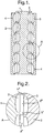
- Figure 3 shows a portion of a mixer comprising an inner drum (1) and an outer sleeve (2). Cavities (3) are provided in the drum and the sleeve so that as the drum rotates about its axis (shown dashed), the drum and the sleeve co-operate to form a cavity transfer mixer. Ports (4) are provided for input and output of the process flow. Means for rotating the drum relative to the sleeve and end seals are not shown. Flow of materials within the mixer is from the bottom towards the top.
- Figure 4 provides a more detailed view of the region "A" in figure 3 . It can be seen that in regions “X I “, “X II “ and “X III " the surface of the drum (1) is relieved and the radial spacings of the confronting surfaces of the drum (1) and the sleeve (2) are relatively large as compared with the corresponding radial spacings in regions "Y I “ and “Y II ". In regions X I , X II and X III the cavities (3) promote CTM-like distributive mixing while in regions Y I and Y II the narrow spacing in the flow path induces an element of extensional flow and CDDM-like dispersive mixing. In this particular embodiment of the mixer the radial spacings in regions X I , X II and X III increase in the direction of flow, while the radial spacings in regions Y I and Y II are constant.
- This example illustrates a class of embodiment which is less preferred than that shown in figures 1 and 2 .
- the region of narrow spacing between the widest part of the drum and the inner surface of the sleeve is now in part crossed by the cavities in the inner wall of the sleeve, which allow some or all of the bulk flow to avoid the regions of high shear Y I and Y II .
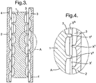
- Figure 5 shows a portion of a mixer comprising a rotating disc (1) and a static disc (2). Cavities (3) are provided in the rotating disc and static disc so that as the former rotates about its axis (shown dashed), the rotating disc and static disc co-operate to form a controlled deformation dynamic mixer. Ports (4) are provided for input and output of the process flow. Means for rotating the rotating disc relative to the static disc and end seals are not shown. Flow of materials within the mixer is from the centre towards the periphery.
- Figure 6 provides a more detailed view of the region "A" in figure 5 . It can be seen that in regions “X I “, “X II “ and “X III " the surfaces of the rotating disc (1) are relieved and the axial spacings of the confronting surfaces of the rotating disc (1) and the static disc (2) are relatively large as compared with the corresponding axial spacings in regions "Y I “ and “Y II ". In regions X I , X II and X III the cavities (3) promote CTM-like distributive mixing while in regions Y I and Y II the narrow spacing in the flow path induces extensional flow and CDDM-like dispersive mixing. In this particular embodiment of the mixer the axial spacings in regions X I , X II and X III increase in the direction of flow, while the radial spacings in regions Y I and Y II are constant.
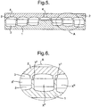
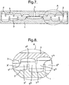
- Figure 7 shows a portion of a mixer comprising a rotating disc (1) and a static disc (2). Cavities (3) are provided in the rotating disc and static disc so that as the former rotates about its axis (shown dashed), the rotating disc and static disc co-operate to form a cavity transfer mixer. Ports (4) are provided for input and output of the process flow. Means for rotating the rotating disc relative to the static disc and end seals are not shown. Flow of materials within the mixer is from the centre towards the periphery.
- Figure 8 provides a more detailed view of the region "A” in figure 7 . It can be seen that in regions “X I “, “X II “, “X III “ and “X IV " the surfaces of the rotating disc (1) and static disc (2) are relieved and the axial spacings of the confronting surfaces of the rotating disc (1) and the static disc (2) are large and significantly increase in the direction of flow. Neither the rotating disc in regions “Y II “ and “Y IV “ nor the static disc in regions “Y I “ and “Y III “ are relieved, thus limiting the tendency for radial leakage flow induced by such large axial spacings. As with example 2, this is a less preferred embodiment of the invention as it is of the class of embodiments in which the narrower part of the spacing between the confronting surfaces is crossed by the mixing cavities.
Landscapes
- Chemical & Material Sciences (AREA)
- Chemical Kinetics & Catalysis (AREA)
- Mixers Of The Rotary Stirring Type (AREA)
- Accessories For Mixers (AREA)
Claims (7)
- Distributive und dispersive Mischvorrichtung, die zwei gegenüberliegende Oberflächen (1, 2) umfasst, die darin Hohlräume (3) aufweisen, die bei einer Relativbewegung der Oberflächen (1, 2) als ein "Cavity Transfer Mixer" und/oder als ein "Controlled Deformation Dynamic Mixer" fungieren,
dadurch gekennzeichnet, dass
der normale Abstand der gegenüberliegenden Oberflächen (1, 2), der der Abstand der Oberflächen in Abwesenheit der Hohlräume (3) ist, in Richtung der Masseströmung in der Weise variiert, dass mehrere Gebiete mit aufeinander folgend engerem (YI, YII, YIII, YIV) und weiterem Abstand (XI, XII, XIII, XIV, XV) der gegenüberliegenden Oberflächen (1, 2) definiert sind,
wobei zumindest eines der Gebiete mit weiterem Abstand (XI, XII, XIII, XIV, XV) der gegenüberliegenden Oberflächen (1, 2) die Hohlräume (3) umfasst. - Distributive und dispersive Mischvorrichtung nach Anspruch 1, wobei die gegenüberliegenden Oberflächen (1, 2) allgemein zylinderförmige Flächen umfassen.
- Distributive und dispersive Mischvorrichtung nach Anspruch 1, wobei die gegenüberliegenden Oberflächen (1, 2) allgemein kegelförmige Flächen umfassen.
- Distributive und dispersive Mischvorrichtung nach Anspruch 1, wobei die gegenüberliegenden Oberflächen (1, 2) allgemein scheibenförmige Oberflächen umfassen.
- Distributive und dispersive Mischvorrichtung nach einem der Ansprüche 1-4, die ferner zumindest ein käfigförmiges Element umfasst, das zwischen den gegenüberliegenden Oberflächen (1, 2) angeordnet ist, wobei die Oberflächen des käfigförmigen Elements im Profil an die gegenüberliegenden Oberflächen (1, 2), gegenüber denen sie jeweils angeordnet sind, angepasst sind.
- Distributive und dispersive Mischvorrichtung nach einem der Ansprüche 1-5, die ferner Gebiete axial angeordneter gegenüberliegender Oberflächen (1, 2) umfasst, die mit Gebieten radial angeordneter gegenüberliegender Oberflächen (1, 2) abwechseln und dadurch irgendeine Leckströmung durch den Mischer verhindern.
- Verwendung der distributiven und dispersiven Mischvorrichtung nach einem der Ansprüche 1-6 für die Behandlung einer Flüssigkeit, einer Emulsion oder eines Gels.
Applications Claiming Priority (2)
| Application Number | Priority Date | Filing Date | Title |
|---|---|---|---|
| GBGB0901954.8A GB0901954D0 (en) | 2009-02-09 | 2009-02-09 | Improvments relating to mixing apparatus |
| PCT/EP2010/051295 WO2010091983A1 (en) | 2009-02-09 | 2010-02-03 | Mixing apparatus of the cddm- and/or ctm-type, and its use |
Publications (2)
| Publication Number | Publication Date |
|---|---|
| EP2393583A1 EP2393583A1 (de) | 2011-12-14 |
| EP2393583B1 true EP2393583B1 (de) | 2017-06-07 |
Family
ID=40469680
Family Applications (1)
| Application Number | Title | Priority Date | Filing Date |
|---|---|---|---|
| EP10701708.9A Active EP2393583B1 (de) | 2009-02-09 | 2010-02-03 | Mischvorrichtung zum verteilenden und dispersiven mischen, sowie deren verwendung |
Country Status (5)
| Country | Link |
|---|---|
| US (1) | US9539551B2 (de) |
| EP (1) | EP2393583B1 (de) |
| BR (1) | BRPI1007976B1 (de) |
| GB (1) | GB0901954D0 (de) |
| WO (1) | WO2010091983A1 (de) |
Families Citing this family (8)
| Publication number | Priority date | Publication date | Assignee | Title |
|---|---|---|---|---|
| US20130258801A1 (en) * | 2010-11-15 | 2013-10-03 | Hindustan Unilever Limited | Mixing apparatus and method for mixing fluids |
| JP5940556B2 (ja) * | 2010-12-28 | 2016-06-29 | ユニリーバー・ナームローゼ・ベンノートシヤープ | エマルジョンの製造方法 |
| WO2013056964A1 (en) | 2011-10-17 | 2013-04-25 | Unilever N.V. | Method for production of edible water-in-oil emulsion |
| GB201121541D0 (en) * | 2011-12-14 | 2012-01-25 | Maelstrom Advanced Process Technologies Ltd | Improved dynamic mixer |
| US20150125416A1 (en) | 2011-12-20 | 2015-05-07 | Conopco, Inc., d/h/a UNILEVER | Method for production of structured liquid and structured liquid |
| KR101714157B1 (ko) * | 2015-06-08 | 2017-03-08 | 현대자동차주식회사 | 금형장치 |
| EP3474675B1 (de) | 2016-06-22 | 2024-07-17 | Unilever IP Holdings B.V. | Herstellung eines konzentrats zur produktion einer vormischung für eiskonfekt |
| JP7049793B2 (ja) * | 2017-09-29 | 2022-04-07 | 株式会社明治 | 微粒化装置 |
Citations (3)
| Publication number | Priority date | Publication date | Assignee | Title |
|---|---|---|---|---|
| US2744287A (en) * | 1952-09-24 | 1956-05-08 | Us Rubber Co | Mill |
| US3867104A (en) * | 1973-04-12 | 1975-02-18 | Monsanto Co | Polymerizer reactor |
| US20040052156A1 (en) * | 2000-11-10 | 2004-03-18 | Brown Christopher John | Dynamic mixer |
Family Cites Families (32)
| Publication number | Priority date | Publication date | Assignee | Title |
|---|---|---|---|---|
| US333788A (en) * | 1886-01-05 | of guatemala | ||
| GB129757A (en) | 1918-06-11 | 1919-07-11 | Christian Ove Joha Christensen | Improved Method of and Means for Producing Emulsion. |
| US2969960A (en) * | 1957-06-05 | 1961-01-31 | Mobay Chemical Corp | Mixing apparatus |
| NL113031C (de) * | 1958-05-29 | 1900-01-01 | ||
| GB930339A (en) * | 1961-05-01 | 1963-07-03 | Metal Box Co Ltd | Improvements in or relating to the extrusion of molten thermoplastic material |
| US3194540A (en) * | 1961-07-28 | 1965-07-13 | Liberty Nat Bank And Trust Com | Homogenizing apparatus |
| US3333828A (en) * | 1965-03-19 | 1967-08-01 | Norton Co | Homogenizer |
| DE1557171B2 (de) | 1966-10-28 | 1970-07-30 | Fr August Neidig Soehne Maschi | Vorrichtung zum Homogenisieren und Mischen fluessiger,breiiger und teigiger Medien |
| US3580545A (en) * | 1969-05-23 | 1971-05-25 | Stauffer Chemical Co | Apparatus for agglomerating dusts and the like |
| USRE29053E (en) * | 1972-05-09 | 1976-11-30 | Mixer-refiner | |
| US4129389A (en) * | 1978-01-30 | 1978-12-12 | Crepaco, Inc. | Agitator construction |
| US4419014A (en) * | 1980-09-23 | 1983-12-06 | Rubber And Plastics Research Association Of Great Britain | Extruder mixer |
| US4421413A (en) * | 1981-09-28 | 1983-12-20 | Sekiguchi Co., Ltd. | Apparatus for continuously emulsifying the liquids |
| DE3235669A1 (de) | 1981-10-20 | 1983-05-05 | VEB Leuna-Werke "Walter Ulbricht", DDR 4220 Leuna | Reaktor zur kontinuierlichen herstellung von epoxidharzen |
| DD207104A3 (de) | 1981-10-20 | 1984-02-15 | Leuna Werke Veb | Nachreaktor zur kontinuierlichen herstellung von epoxidharzen |
| US4582433A (en) * | 1984-12-20 | 1986-04-15 | Usm Corporation | Rotary processors and methods for liquid-liquid extraction |
| US4680132A (en) * | 1982-03-26 | 1987-07-14 | Lever Brothers Company | Processing detergent bars with a cavity transfer mixer to reduce grittiness |
| FI830997L (fi) * | 1982-03-29 | 1983-09-30 | Unilever Nv | Foerfarande foer framstaellning av en tvaolstaong |
| BR8301601A (pt) | 1982-03-29 | 1983-12-06 | Unilever Nv | Processo de aerar material detergente contendo sabao |
| US4840810A (en) * | 1985-03-27 | 1989-06-20 | Lever Brothers Company | Process for the preparation of an edible fat-containing product |
| US4844928A (en) * | 1985-03-27 | 1989-07-04 | Lever Brothers Company | Process for the preparation of an edible fat-containing product |
| GB8928388D0 (en) | 1989-12-15 | 1990-02-21 | Shell Int Research | Multistage reactor |
| GB2267653B (en) * | 1992-06-09 | 1995-08-09 | Frenkel Ag C D | Mixing machinery of the transfermix type |
| US5599507A (en) * | 1994-11-09 | 1997-02-04 | Shaw; Gordon | Reactor apparatus for preparing a polymeric material |
| ZA9510847B (en) * | 1994-12-23 | 1997-06-20 | Unilever Plc | Process for the production of liquid compositions |
| EP0719582B1 (de) * | 1994-12-30 | 1999-03-03 | Karl Fischer Industrieanlagen Gmbh | Reaktorvorrichtung für fliessfähige und höherviskose Medien |
| EP0833114A4 (de) * | 1995-04-18 | 1998-05-20 | Advanced Molecular Technologie | Verfahren und vorrichtung zur heizung einer flüssigkeit |
| GB2308076B (en) * | 1997-04-11 | 1998-04-22 | Tecexec Limited | A mixing apparatus |
| CA2217374A1 (en) * | 1997-09-29 | 1999-03-29 | Andre Luciani | Extensional flow mixer |
| DE10001477B4 (de) | 2000-01-15 | 2005-04-28 | Zimmer Ag | Diskontinuierliches Polykondensationsverfahren und Rührscheibenreaktor hierfür |
| FI114299B (fi) * | 2001-06-25 | 2004-09-30 | Conenor Oy | Menetelmä eri materiaalien käsittelemiseksi ja materiaalinkäsittelylaite |
| KR20070093254A (ko) | 2006-03-13 | 2007-09-18 | (주)퓨쳐솔루션 | 유중 수적형 에멀젼 연료의 제조장치 |
-
2009
- 2009-02-09 GB GBGB0901954.8A patent/GB0901954D0/en not_active Ceased
-
2010
- 2010-02-03 WO PCT/EP2010/051295 patent/WO2010091983A1/en not_active Ceased
- 2010-02-03 EP EP10701708.9A patent/EP2393583B1/de active Active
- 2010-02-03 US US13/146,651 patent/US9539551B2/en active Active
- 2010-02-03 BR BRPI1007976-9A patent/BRPI1007976B1/pt active IP Right Grant
Patent Citations (3)
| Publication number | Priority date | Publication date | Assignee | Title |
|---|---|---|---|---|
| US2744287A (en) * | 1952-09-24 | 1956-05-08 | Us Rubber Co | Mill |
| US3867104A (en) * | 1973-04-12 | 1975-02-18 | Monsanto Co | Polymerizer reactor |
| US20040052156A1 (en) * | 2000-11-10 | 2004-03-18 | Brown Christopher John | Dynamic mixer |
Also Published As
| Publication number | Publication date |
|---|---|
| BRPI1007976A2 (pt) | 2016-03-01 |
| BRPI1007976B1 (pt) | 2020-08-04 |
| WO2010091983A1 (en) | 2010-08-19 |
| US20120113743A1 (en) | 2012-05-10 |
| GB0901954D0 (en) | 2009-03-11 |
| US9539551B2 (en) | 2017-01-10 |
| EP2393583A1 (de) | 2011-12-14 |
Similar Documents
| Publication | Publication Date | Title |
|---|---|---|
| EP2393583B1 (de) | Mischvorrichtung zum verteilenden und dispersiven mischen, sowie deren verwendung | |
| US20120127826A1 (en) | Mixing apparatus of the cddm- or ctm-type, and its use | |
| US7237943B2 (en) | Dynamic fluid mixer | |
| EP2393581B1 (de) | Mischvorrichtung des typs cddm zum verteilenden und dispersiven mischen, sowie deren verwendung | |
| JP4369999B2 (ja) | 混合装置 | |
| EP2790822B1 (de) | Verbesserter dynamischer mischer | |
| EP3367809B1 (de) | Vorrichtung und verfahren zur belüftung eines lebensmittels | |
| EP2775853B1 (de) | Vorrichtung und verfahren zur belüftung eines lebensmittels | |
| US20100220545A1 (en) | Mixer and method of mixing | |
| EP2640498B1 (de) | Vorrichtung und verfahren zum mischen mindestens zweier fluide | |
| EP2755749B1 (de) | Mischvorrichtung sowie verfahren zur herstellung einer essbaren dispersion in solch einer vorrichtung | |
| CN102725065B (zh) | 研磨机和研磨方法 | |
| NL2017029A (en) | Spinning disc reactor | |
| WO2000059617A1 (en) | Mixing apparatus | |
| US20240165629A1 (en) | Colloid mill | |
| RU2626201C1 (ru) | Мешалка | |
| CN114570233B (zh) | 一种带有空化效应的高剪切机 | |
| RU2229330C1 (ru) | Роторный кавитационный диспергатор | |
| CN117205784A (zh) | 分散装置和电极材料生产系统 | |
| UA124851C2 (uk) | Роторний апарат для отримання високодисперсних рідинних середовищ | |
| UA25017U (en) | Working unit of rotary-pulsating apparatus |
Legal Events
| Date | Code | Title | Description |
|---|---|---|---|
| PUAI | Public reference made under article 153(3) epc to a published international application that has entered the european phase |
Free format text: ORIGINAL CODE: 0009012 |
|
| 17P | Request for examination filed |
Effective date: 20110627 |
|
| AK | Designated contracting states |
Kind code of ref document: A1 Designated state(s): AT BE BG CH CY CZ DE DK EE ES FI FR GB GR HR HU IE IS IT LI LT LU LV MC MK MT NL NO PL PT RO SE SI SK SM TR |
|
| DAX | Request for extension of the european patent (deleted) | ||
| 17Q | First examination report despatched |
Effective date: 20130124 |
|
| STAA | Information on the status of an ep patent application or granted ep patent |
Free format text: STATUS: EXAMINATION IS IN PROGRESS |
|
| GRAP | Despatch of communication of intention to grant a patent |
Free format text: ORIGINAL CODE: EPIDOSNIGR1 |
|
| STAA | Information on the status of an ep patent application or granted ep patent |
Free format text: STATUS: GRANT OF PATENT IS INTENDED |
|
| INTG | Intention to grant announced |
Effective date: 20170203 |
|
| RIC1 | Information provided on ipc code assigned before grant |
Ipc: B01F 7/00 20060101AFI20170124BHEP Ipc: B01F 3/08 20060101ALN20170124BHEP |
|
| GRAS | Grant fee paid |
Free format text: ORIGINAL CODE: EPIDOSNIGR3 |
|
| GRAA | (expected) grant |
Free format text: ORIGINAL CODE: 0009210 |
|
| STAA | Information on the status of an ep patent application or granted ep patent |
Free format text: STATUS: THE PATENT HAS BEEN GRANTED |
|
| AK | Designated contracting states |
Kind code of ref document: B1 Designated state(s): AT BE BG CH CY CZ DE DK EE ES FI FR GB GR HR HU IE IS IT LI LT LU LV MC MK MT NL NO PL PT RO SE SI SK SM TR |
|
| REG | Reference to a national code |
Ref country code: GB Ref legal event code: FG4D |
|
| GRAA | (expected) grant |
Free format text: ORIGINAL CODE: 0009210 |
|
| REG | Reference to a national code |
Ref country code: CH Ref legal event code: EP Ref country code: AT Ref legal event code: REF Ref document number: 898794 Country of ref document: AT Kind code of ref document: T Effective date: 20170615 |
|
| REG | Reference to a national code |
Ref country code: IE Ref legal event code: FG4D |
|
| REG | Reference to a national code |
Ref country code: DE Ref legal event code: R096 Ref document number: 602010042806 Country of ref document: DE |
|
| REG | Reference to a national code |
Ref country code: NL Ref legal event code: MP Effective date: 20170607 |
|
| REG | Reference to a national code |
Ref country code: LT Ref legal event code: MG4D |
|
| PG25 | Lapsed in a contracting state [announced via postgrant information from national office to epo] |
Ref country code: GR Free format text: LAPSE BECAUSE OF FAILURE TO SUBMIT A TRANSLATION OF THE DESCRIPTION OR TO PAY THE FEE WITHIN THE PRESCRIBED TIME-LIMIT Effective date: 20170908 Ref country code: LT Free format text: LAPSE BECAUSE OF FAILURE TO SUBMIT A TRANSLATION OF THE DESCRIPTION OR TO PAY THE FEE WITHIN THE PRESCRIBED TIME-LIMIT Effective date: 20170607 Ref country code: FI Free format text: LAPSE BECAUSE OF FAILURE TO SUBMIT A TRANSLATION OF THE DESCRIPTION OR TO PAY THE FEE WITHIN THE PRESCRIBED TIME-LIMIT Effective date: 20170607 Ref country code: NO Free format text: LAPSE BECAUSE OF FAILURE TO SUBMIT A TRANSLATION OF THE DESCRIPTION OR TO PAY THE FEE WITHIN THE PRESCRIBED TIME-LIMIT Effective date: 20170907 Ref country code: HR Free format text: LAPSE BECAUSE OF FAILURE TO SUBMIT A TRANSLATION OF THE DESCRIPTION OR TO PAY THE FEE WITHIN THE PRESCRIBED TIME-LIMIT Effective date: 20170607 Ref country code: ES Free format text: LAPSE BECAUSE OF FAILURE TO SUBMIT A TRANSLATION OF THE DESCRIPTION OR TO PAY THE FEE WITHIN THE PRESCRIBED TIME-LIMIT Effective date: 20170607 |
|
| REG | Reference to a national code |
Ref country code: AT Ref legal event code: MK05 Ref document number: 898794 Country of ref document: AT Kind code of ref document: T Effective date: 20170607 |
|
| PG25 | Lapsed in a contracting state [announced via postgrant information from national office to epo] |
Ref country code: SE Free format text: LAPSE BECAUSE OF FAILURE TO SUBMIT A TRANSLATION OF THE DESCRIPTION OR TO PAY THE FEE WITHIN THE PRESCRIBED TIME-LIMIT Effective date: 20170607 Ref country code: NL Free format text: LAPSE BECAUSE OF FAILURE TO SUBMIT A TRANSLATION OF THE DESCRIPTION OR TO PAY THE FEE WITHIN THE PRESCRIBED TIME-LIMIT Effective date: 20170607 Ref country code: LV Free format text: LAPSE BECAUSE OF FAILURE TO SUBMIT A TRANSLATION OF THE DESCRIPTION OR TO PAY THE FEE WITHIN THE PRESCRIBED TIME-LIMIT Effective date: 20170607 Ref country code: BG Free format text: LAPSE BECAUSE OF FAILURE TO SUBMIT A TRANSLATION OF THE DESCRIPTION OR TO PAY THE FEE WITHIN THE PRESCRIBED TIME-LIMIT Effective date: 20170907 |
|
| PG25 | Lapsed in a contracting state [announced via postgrant information from national office to epo] |
Ref country code: CZ Free format text: LAPSE BECAUSE OF FAILURE TO SUBMIT A TRANSLATION OF THE DESCRIPTION OR TO PAY THE FEE WITHIN THE PRESCRIBED TIME-LIMIT Effective date: 20170607 Ref country code: EE Free format text: LAPSE BECAUSE OF FAILURE TO SUBMIT A TRANSLATION OF THE DESCRIPTION OR TO PAY THE FEE WITHIN THE PRESCRIBED TIME-LIMIT Effective date: 20170607 Ref country code: AT Free format text: LAPSE BECAUSE OF FAILURE TO SUBMIT A TRANSLATION OF THE DESCRIPTION OR TO PAY THE FEE WITHIN THE PRESCRIBED TIME-LIMIT Effective date: 20170607 Ref country code: RO Free format text: LAPSE BECAUSE OF FAILURE TO SUBMIT A TRANSLATION OF THE DESCRIPTION OR TO PAY THE FEE WITHIN THE PRESCRIBED TIME-LIMIT Effective date: 20170607 Ref country code: SK Free format text: LAPSE BECAUSE OF FAILURE TO SUBMIT A TRANSLATION OF THE DESCRIPTION OR TO PAY THE FEE WITHIN THE PRESCRIBED TIME-LIMIT Effective date: 20170607 |
|
| REG | Reference to a national code |
Ref country code: FR Ref legal event code: PLFP Year of fee payment: 9 |
|
| PG25 | Lapsed in a contracting state [announced via postgrant information from national office to epo] |
Ref country code: SM Free format text: LAPSE BECAUSE OF FAILURE TO SUBMIT A TRANSLATION OF THE DESCRIPTION OR TO PAY THE FEE WITHIN THE PRESCRIBED TIME-LIMIT Effective date: 20170607 Ref country code: PL Free format text: LAPSE BECAUSE OF FAILURE TO SUBMIT A TRANSLATION OF THE DESCRIPTION OR TO PAY THE FEE WITHIN THE PRESCRIBED TIME-LIMIT Effective date: 20170607 Ref country code: IS Free format text: LAPSE BECAUSE OF FAILURE TO SUBMIT A TRANSLATION OF THE DESCRIPTION OR TO PAY THE FEE WITHIN THE PRESCRIBED TIME-LIMIT Effective date: 20171007 |
|
| REG | Reference to a national code |
Ref country code: DE Ref legal event code: R097 Ref document number: 602010042806 Country of ref document: DE |
|
| PLBE | No opposition filed within time limit |
Free format text: ORIGINAL CODE: 0009261 |
|
| STAA | Information on the status of an ep patent application or granted ep patent |
Free format text: STATUS: NO OPPOSITION FILED WITHIN TIME LIMIT |
|
| PG25 | Lapsed in a contracting state [announced via postgrant information from national office to epo] |
Ref country code: DK Free format text: LAPSE BECAUSE OF FAILURE TO SUBMIT A TRANSLATION OF THE DESCRIPTION OR TO PAY THE FEE WITHIN THE PRESCRIBED TIME-LIMIT Effective date: 20170607 |
|
| 26N | No opposition filed |
Effective date: 20180308 |
|
| PG25 | Lapsed in a contracting state [announced via postgrant information from national office to epo] |
Ref country code: SI Free format text: LAPSE BECAUSE OF FAILURE TO SUBMIT A TRANSLATION OF THE DESCRIPTION OR TO PAY THE FEE WITHIN THE PRESCRIBED TIME-LIMIT Effective date: 20170607 |
|
| REG | Reference to a national code |
Ref country code: CH Ref legal event code: PL |
|
| PG25 | Lapsed in a contracting state [announced via postgrant information from national office to epo] |
Ref country code: MC Free format text: LAPSE BECAUSE OF FAILURE TO SUBMIT A TRANSLATION OF THE DESCRIPTION OR TO PAY THE FEE WITHIN THE PRESCRIBED TIME-LIMIT Effective date: 20170607 |
|
| REG | Reference to a national code |
Ref country code: IE Ref legal event code: MM4A |
|
| REG | Reference to a national code |
Ref country code: BE Ref legal event code: MM Effective date: 20180228 |
|
| PG25 | Lapsed in a contracting state [announced via postgrant information from national office to epo] |
Ref country code: LI Free format text: LAPSE BECAUSE OF NON-PAYMENT OF DUE FEES Effective date: 20180228 Ref country code: CH Free format text: LAPSE BECAUSE OF NON-PAYMENT OF DUE FEES Effective date: 20180228 Ref country code: LU Free format text: LAPSE BECAUSE OF NON-PAYMENT OF DUE FEES Effective date: 20180203 |
|
| PG25 | Lapsed in a contracting state [announced via postgrant information from national office to epo] |
Ref country code: IE Free format text: LAPSE BECAUSE OF NON-PAYMENT OF DUE FEES Effective date: 20180203 |
|
| PG25 | Lapsed in a contracting state [announced via postgrant information from national office to epo] |
Ref country code: BE Free format text: LAPSE BECAUSE OF NON-PAYMENT OF DUE FEES Effective date: 20180228 |
|
| PG25 | Lapsed in a contracting state [announced via postgrant information from national office to epo] |
Ref country code: MT Free format text: LAPSE BECAUSE OF NON-PAYMENT OF DUE FEES Effective date: 20180203 |
|
| PG25 | Lapsed in a contracting state [announced via postgrant information from national office to epo] |
Ref country code: PT Free format text: LAPSE BECAUSE OF FAILURE TO SUBMIT A TRANSLATION OF THE DESCRIPTION OR TO PAY THE FEE WITHIN THE PRESCRIBED TIME-LIMIT Effective date: 20170607 Ref country code: HU Free format text: LAPSE BECAUSE OF FAILURE TO SUBMIT A TRANSLATION OF THE DESCRIPTION OR TO PAY THE FEE WITHIN THE PRESCRIBED TIME-LIMIT; INVALID AB INITIO Effective date: 20100203 |
|
| PG25 | Lapsed in a contracting state [announced via postgrant information from national office to epo] |
Ref country code: CY Free format text: LAPSE BECAUSE OF FAILURE TO SUBMIT A TRANSLATION OF THE DESCRIPTION OR TO PAY THE FEE WITHIN THE PRESCRIBED TIME-LIMIT Effective date: 20170607 Ref country code: MK Free format text: LAPSE BECAUSE OF NON-PAYMENT OF DUE FEES Effective date: 20170607 |
|
| REG | Reference to a national code |
Ref country code: DE Ref legal event code: R081 Ref document number: 602010042806 Country of ref document: DE Owner name: UNILEVER IP HOLDINGS B.V., NL Free format text: FORMER OWNER: UNILEVER N.V., ROTTERDAM, NL Ref country code: DE Ref legal event code: R081 Ref document number: 602010042806 Country of ref document: DE Owner name: MAGNUM IP HOLDINGS B.V., NL Free format text: FORMER OWNER: UNILEVER N.V., ROTTERDAM, NL |
|
| REG | Reference to a national code |
Ref country code: DE Ref legal event code: R079 Ref document number: 602010042806 Country of ref document: DE Free format text: PREVIOUS MAIN CLASS: B01F0007000000 Ipc: B01F0027000000 |
|
| REG | Reference to a national code |
Ref country code: GB Ref legal event code: 732E Free format text: REGISTERED BETWEEN 20211125 AND 20211201 |
|
| P01 | Opt-out of the competence of the unified patent court (upc) registered |
Effective date: 20230426 |
|
| PGFP | Annual fee paid to national office [announced via postgrant information from national office to epo] |
Ref country code: DE Payment date: 20250218 Year of fee payment: 16 |
|
| PGFP | Annual fee paid to national office [announced via postgrant information from national office to epo] |
Ref country code: FR Payment date: 20250221 Year of fee payment: 16 |
|
| PGFP | Annual fee paid to national office [announced via postgrant information from national office to epo] |
Ref country code: IT Payment date: 20250221 Year of fee payment: 16 Ref country code: GB Payment date: 20250219 Year of fee payment: 16 |
|
| PGFP | Annual fee paid to national office [announced via postgrant information from national office to epo] |
Ref country code: TR Payment date: 20250130 Year of fee payment: 16 |
|
| REG | Reference to a national code |
Ref country code: GB Ref legal event code: 732E Free format text: REGISTERED BETWEEN 20250828 AND 20250903 |
|
| REG | Reference to a national code |
Ref country code: DE Ref legal event code: R081 Ref document number: 602010042806 Country of ref document: DE Owner name: MAGNUM IP HOLDINGS B.V., NL Free format text: FORMER OWNER: UNILEVER IP HOLDINGS B.V., ROTTERDAM, NL |