EP2393280A2 - Bilderzeugungsvorichtung mit Autofokusfunktion mit mehreren Bandpassfiltern und Autofokusverfahren dafür - Google Patents
Bilderzeugungsvorichtung mit Autofokusfunktion mit mehreren Bandpassfiltern und Autofokusverfahren dafür Download PDFInfo
- Publication number
- EP2393280A2 EP2393280A2 EP11172934A EP11172934A EP2393280A2 EP 2393280 A2 EP2393280 A2 EP 2393280A2 EP 11172934 A EP11172934 A EP 11172934A EP 11172934 A EP11172934 A EP 11172934A EP 2393280 A2 EP2393280 A2 EP 2393280A2
- Authority
- EP
- European Patent Office
- Prior art keywords
- focus
- focus signal
- lens
- defocus
- focus lens
- Prior art date
- Legal status (The legal status is an assumption and is not a legal conclusion. Google has not performed a legal analysis and makes no representation as to the accuracy of the status listed.)
- Withdrawn
Links
Images






Classifications
-
- H—ELECTRICITY
- H04—ELECTRIC COMMUNICATION TECHNIQUE
- H04N—PICTORIAL COMMUNICATION, e.g. TELEVISION
- H04N23/00—Cameras or camera modules comprising electronic image sensors; Control thereof
- H04N23/60—Control of cameras or camera modules
- H04N23/67—Focus control based on electronic image sensor signals
-
- H—ELECTRICITY
- H04—ELECTRIC COMMUNICATION TECHNIQUE
- H04N—PICTORIAL COMMUNICATION, e.g. TELEVISION
- H04N23/00—Cameras or camera modules comprising electronic image sensors; Control thereof
- H04N23/60—Control of cameras or camera modules
- H04N23/67—Focus control based on electronic image sensor signals
- H04N23/673—Focus control based on electronic image sensor signals based on contrast or high frequency components of image signals, e.g. hill climbing method
-
- G—PHYSICS
- G02—OPTICS
- G02B—OPTICAL ELEMENTS, SYSTEMS OR APPARATUS
- G02B7/00—Mountings, adjusting means, or light-tight connections, for optical elements
- G02B7/28—Systems for automatic generation of focusing signals
- G02B7/36—Systems for automatic generation of focusing signals using image sharpness techniques, e.g. image processing techniques for generating autofocus signals
Definitions
- the present invention relates auto focusing such as for an imaging apparatus.
- AF automatic focusing
- Modern cameras support an automatic focusing (AF) function, which enables automatic focus adjustment.
- AF systems use a contrast method or phase difference detection method.
- the phase different detection method can focus in a short time.
- a dedicated detection apparatus is required with a separate optic system that guides light for focus detection.
- the phase difference detection method is generally used in a digital single-lens reflex (DSLR) camera.
- DSLR digital single-lens reflex
- the contrast method does not require a separate space, it is mainly used in a small-sized compact camera. However, since the contrast method cannot directly measure an amount of defocus, the measurement should be repeated several times.
- An object of the invention is to provide an imaging apparatus and focusing method that calculates a plurality of focus signal values for a plurality of bands of a captured image signal, calculates an amount of defocus of a focus lens, based on focus signal values calculated for two positions, and controls a position of the focus lens depending on the calculated amount of defocus.
- an imaging apparatus includes a lens unit including an optical system having a focus lens; a driving unit that drives the lens unit; an image pickup unit that detects light having passed through the lens unit to generate an image signal; an auto focusing unit that calculates and outputs a plurality of focus signal values for a plurality of frequency bands of the image signal generated in the image pickup unit; and a control unit that calculates an amount of defocus of the focus lens, based on first focus signal values, which are the plurality of focus signal values at a first position of the focus lens, and second focus signal values, which are the plurality of focus signal values at a second position of the focus lens, and controls the driving unit so that a position of the focus lens is moved depending on the calculated amount of defocus.
- An auto focusing method includes detecting light having passed through a lens unit to generate an image signal; calculating a plurality of focus signal values for a plurality of frequency bands of the generated image signal; calculating an amount of defocus of the focus lens, based on first focus signal values, which are the plurality of focus signal values at a first position of the focus lens, and second focus signal values, which are the plurality of focus signal values at a second position of the focus lens; and driving the focus lens so that a position of the focus lens is moved depending on the calculated amount of defocus.
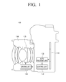
- FIG. 1 is a block diagram showing a configuration of a camera according to an exemplary embodiment of the invention
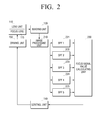
- FIG. 2 is a block diagram showing a detailed configuration of a camera according to an exemplary embodiment of the invention
- FIG. 3 is a flow chart showing an auto focusing method according to an exemplary embodiment of the invention.
- FIGS. 4A and 4B are graphs showing focus signal values depending on focus lens positions and frequencies according to an exemplary embodiment of the invention.
- FIGS. 5A to 5D are graphs showing focus signal values and focus signal ratios depending on focus lens positions and frequencies according to an exemplary embodiment of the invention
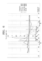
- FIG. 6 is a graph showing focus signal ratios depending on focus lens positions in four frequency bands according to an exemplary embodiment of the invention.
- FIG. 7 shows an example of focus signals that are output from five band pass filters according to an exemplary embodiment of the invention
- FIG. 8 illustrates a process of detecting an on-focus position through defocus amount calculations of two times according to an exemplary embodiment of the invention
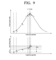
- FIG. 9 illustrates a process of detecting an on-focus position through a defocus amount calculation of one time and performing a three-point interpolation with a driving interval of 3F ⁇ according to an exemplary embodiment of the invention
- FIG. 10 illustrates a process of detecting an on-focus position through a defocus amount calculation of one time and performing a three-point interpolation with a driving interval of 6F ⁇ according to an exemplary embodiment of the invention
- FIG. 11 illustrates a process of directly moving to a position adjacent to an on-focus position through a defocus amount calculation of one time and performing a three-point interpolation according to an exemplary embodiment of the invention
- FIG. 12 illustrates an auto focusing process when an initial position is a position beyond an on-focus position according to an exemplary embodiment of the invention.
- FIG. 1 is a block diagram showing a configuration of a camera 100 having an auto focusing device according to an exemplary embodiment of the invention.
- the camera may include a lens unit 110, an image pickup unit 120, an auto focusing unit 130, a control unit 140 and a driving unit 150.
- the lens unit 110 may gather light from a subject and form an image on the image pickup unit 120.
- the lens unit 110 may consist of an optic system including a plurality of lenses, which lenses are formed into optical groups according to their functions.
- the lens unit 110 may include a focus lens 115 that performs a focusing function.
- the position for the focus lens 115 may be moved to focus the lens unit 110.
- the driving unit 150 may move the focus lens 115 to an on-focus position.
- the image pickup unit 120 may detect light having passed through the lens unit 110 to generate an image signal about a subject image.
- a film is put on the image pickup unit 120.
- image sensors are arranged on the image pickup unit 120.
- a digital camera will be described as an example.
- Image sensors for exposing a subject image may be disposed on the image pickup unit 120.
- Image sensors typically used in digital cameras broadly speaking may include, for example, charge-coupled devices (CCD) and complementary metal-oxide-semiconductors (CMOS), which differ in their technical mechanism but operate on substantially the same basic principle.
- CCD charge-coupled devices
- CMOS complementary metal-oxide-semiconductors
- the image pickup unit 120 transmits the generated image signal to the auto focusing unit 130.
- the auto focusing unit 130 may calculate and output a plurality of focus signal values for a plurality of bands of the image signal generated in the image pickup unit 120, with respect to a specific position of the focus lens 115.
- the auto focusing unit 130 will be specifically described below with reference to FIG. 2 .
- FIG. 2 is a block diagram showing a detailed configuration of the camera 100 according to an exemplary embodiment of the invention.
- the auto focusing unit 130 may include an image processing unit 210, a plurality of band pass filters 221 to 225 and a focus signal value calculating unit 230.
- the image processing unit 210 may extract a partial area of the image signal generated in the image pickup unit 120.
- the partial area of the generated image signal indicates a part that is used for focus detection.
- the camera may be adapted to focus a partial area of the captured image, in general, a partial area of a central part of a screen.
- the invention is not limited thereto.
- the camera may be adapted to detect a focus for various parts of a captured image signal.
- the camera 100 may focus the partial area extracted by the image processing unit 210, thereby reducing calculations for auto focusing and increasing focusing speed.
- the band pass filters 221 to 225 may pass different bands of the processed image signal, respectively. Specifically, the band pass filters 221 to 225 may have a same band width and intermediate frequencies thereof may be sequentially increased from the lowest frequency at a predetermined interval. For example, it is assumed that the band pass filters include BPF1 221 to BPF5 225 and the respective filters have a band width of 5 1p/mm and intermediate frequencies thereof are 5 lp/mm, 10 lp/mm, 15 1p/mm, 20 lp/mm and 25 lp/mm, respectively.
- a pass band of the BPF1 221 is 2.5 to 7.5 lp/mm
- a pass band of the BPF2 222 is 7.5 to 12.5 lp/mm
- a pass band of the BPF3 223 is 12.5 to 17.5 1p/mm
- a pass band of the BPF4 224 is 17.5 to 22.5 lp/mm
- a pass band of the BPF5 225 is 22.5 to 27.5 lp/mm.
- a focus signal of a low frequency band has a wide peak width, it may be useful for calculation of a driving direction of the focus lens 115. Since a focus signal of a high frequency band has a narrow peak width at an on-focus position, it may be useful for precise focus detection. Accordingly, when an auto focusing function is performed using a plurality of band pass filters, both low and high frequency bands of the focus signal can be used, so that it is possible to perform a more precise auto focusing.
- the number, the intermediate frequencies and band widths of the band pass filters are not limited to the above and can be variously changed.
- the focus signal value calculating unit 230 may be input with image signals of the respective bands having passed through the band pass filters 221 to 225. For example, in FIG. 2 , the focus signal value calculating unit 230 receives the image signals of five bands from the five band pass filters.
- the focus signal value calculating unit 230 may calculate focus signal values for the image signals of respective bands.
- the focus signal value calculating unit 230 may calculate one focus signal value for an image signal of a band having passed through one of the band pass filters. Therefore, the number of focus signal values generated by the focus signal value calculating unit 230 may be the same as the number of the band pass filters.
- the focus signal value calculating unit 230 generates five focus signal values, i.e., a focus signal value a for an image signal having passed through BPF1 221, a focus signal value b for an image signal having passed through BPF2 222, a focus signal value c for an image signal having passed through BPF3 223, a focus signal value d for an image signal having passed through BPF4 224 and a focus signal value e for an image signal having passed through BPF5 225.
- the focus signal values may be used to detect a focus and one value is calculated for an image signal of one band.
- the focus signal value may be a contrast value. This is to perform auto focusing by the contrast method.
- the auto focusing unit 130 having the configuration as described above may calculate focus signal values for a plurality of bands with respect to a specific position of the focus lens 115. Then, the auto focusing unit 130 may transmit the calculated focus signal values to the control unit 140.
- the control unit 140 may receive the focus signal values calculated in the auto focusing unit 130.
- the control unit 140 may calculate amounts of defocus of the focus lens 115, based on first focus signal values, which are focus signal values at a first position of the focus lens 115, and second focus signal values, which are focus signal values at a second position of the focus lens 115, and may control the driving unit 150 so that a position of the focus lens 115 is moved depending on the calculated amounts of defocus.
- the amount of defocus is a value indicating a degree of deviation of the focus lens 115 from an on-focus position (i.e., in focus position).
- control unit 140 may receive the first focus signal values from the auto focusing unit 130 while the focus lens 115 is at a first position. Then, the control unit 140 may control the driving unit 150 so that the focus lens 115 is moved to a second position. Then, the control unit 140 may receive the second focus signal values from the auto focusing unit 130 while the focus lens 115 is at the second position.
- the first position is a previous position of the focus lens 115 and the second position is a current position of the focus lens 115.
- the control unit 140 may calculate a focus signal ratio (second focus signal value/first focus signal value) that is a ratio of the second focus signal value to the first focus signal value for each of the bands.
- a focus signal ratio (second focus signal value/first focus signal value) that is a ratio of the second focus signal value to the first focus signal value for each of the bands.
- one focus signal ratio per each band may be calculated.
- the control unit 140 calculates the focus signal ratio values for each band with respect to two positions of the focus lens 115.
- the focus signal value calculating unit 230 may generate a focus signal value a1 for an image signal having passed through BPF1 221, a focus signal value b1 for an image signal having passed through BPF2 222, a focus signal value c1 for an image signal having passed through BPF3 223, a focus signal value d1 for an image signal having passed through BPF4 224 and a focus signal value e1 for an image signal having passed through BPF5 225, and while the focus lens 115 is at the second position, the focus signal value calculating unit 230 may generate a focus signal value a2 for an image signal having passed through BPF1 221, a focus signal value b2 for an image signal having passed through BPF2 222, a focus signal value c2 for an image signal having passed through BPF3 223, a focus signal value d2 for an image signal having passed through BPF4 224 and a focus signal value e2 for an image signal having passed
- the control unit 140 may determine whether the focus signal ratios are larger than or equal to 1 or smaller than 1. In this case, accuracy is high when it is determined whether the focus signal ratio of a low frequency band is larger than or equal to 1 or smaller than 1. This is because a focus signal of a low frequency band has a gentle peak and less noise. Accordingly, the control unit 140 may determine whether a focus signal ratio for the lowest frequency band of a plurality of bands is larger than or equal to 1 or smaller than 1.
- the focus signal ratios are larger than or equal to 1, it indicates that movement of the focus lens 115 from the first position to the second position is in a direction approaching the on-focus position.
- the focus signal ratios are smaller than 1, it indicates that a movement of the focus lens 115 from the first position to the second position is in a direction away from the on-focus position.
- the control unit 140 may cause the focus lens 115 to be driven in a direction from the first position to the second position.
- the control unit 140 may cause the focus lens 115 to be driven in a direction opposite to the moving direction from the first position to the second position.
- control unit 140 may determine the driving direction of the focus lens depending on whether the focus signal ratios for the plurality of bands are larger than or equal to 1 or smaller than 1.
- control unit 140 may calculate an amount of defocus corresponding to a band having the largest focus signal ratio. To the contrary, when the focus signal ratios for the plurality of bands are smaller than 1, the control unit 140 may calculate an amount of defocus corresponding to a band having the smallest focus signal ratio.
- FIG. 6 is a graph showing focus signal ratios depending on positions of the focus lens 115 in four frequency bands.
- an x axis of the graph indicates amounts of defocus
- a y axis indicates focus signal ratios
- the four lines indicate ratios for four frequency bands.
- a position at which an amount of defocus is zero indicates an on-focus position.
- the focus signal ratios are larger than 1 in a left side (an area in which an amount of defocus is minus) of the on-focus position (at which an amount of defocus is zero) and the focus signal ratios are smaller than 1 in a right side (an area in which an amount of defocus is plus).
- the focus signal ratios are larger than 1, the moving direction from the first position to the second position (the current moving direction) of the focus lens 115 is a direction approaching the on-focus position.
- the focus signal ratios are smaller than 1, the current moving direction of the focus lens 115 is a direction away from the on-focus position.
- the focus signal ratios have peak values near to the on-focus position, and for the lower the frequency bands, the peaks are away from the on-focus position.
- FIG. 6 it can be seen in an area A that the focus signal ratio of the image signal having the highest frequency band (25 to 30 lp/mm) is larger than the focus signal ratios of the other frequency bands. Also, it can be seen in an area B that the focus signal ratio of the image signal having the second-highest frequency band (12.5 to 17.5 1p/mm) is largest. In addition, it can be seen in an area C that the focus signal ratio of the image signal having the third-highest frequency band (7.5 to 12.5 lp/mm) is largest. Further, it can be seen in an area having minus amounts of defocus deviating from the area C that the focus signal ratio of the image signal having the lowest frequency band (2.5 to 7.5 1p/mm) is largest.
- FIG. 6 it can be seen in an area a that the focus signal ratio of the image signal having the highest frequency band (25 to 30 lp/mm) is smaller than the focus signal ratios of the other frequency bands. Also, it can be seen in an area b that the focus signal ratio of the image signal having the second-highest frequency band (12.5 to 17.5 1p/mm) is smallest. In addition, it can be seen in an area c that the focus signal ratio of the image signal having the third-highest frequency band (7.5 to 12.5 lp/mm) is smallest. Further, it can be seen in an area having plus amounts of defocus deviating from the area c that the focus signal ratio of the image signal having the lowest frequency band (2.5 to 7.5 lp/mm) is smallest.
- control unit 140 may calculate the amount of defocus of the current focus lens 115, based on the focus signal ratios for respective bands of the previous and current positions of the focus lens 115.
- the control unit 140 selects a band having the largest focus signal ratio from the plurality of bands.
- the control unit 140 can know that the amount of defocus of the current focus lens 115 belongs to the range A. Therefore, the control unit 140 may set, as the amount of defocus of the current focus lens 115, -0.2 that is an intermediate value of the range A. In addition, since the focus signal ratio calculated by the control unit 140 is larger than or equal to 1, the control unit 140 may set the moving direction of the focus lens 115 to be same as the current moving direction.
- the control unit 140 can know that the amount of defocus of the current focus lens 115 belongs to the range B. Therefore, the control unit 140 may set, as the amount of defocus of the current focus lens 115, -0.6 that is an intermediate value of the range B. In addition, since the focus signal ratio calculated by the control unit 140 is larger than or equal to 1, the control unit 140 may set the moving direction of the focus lens 115 to be same as the current moving direction.
- the control unit 140 can know that the amount of defocus of the current focus lens 115 belongs to the range C. Therefore, the control unit 140 may set, as the amount of defocus of the current focus lens 115, -1 that is an intermediate value of the range C. In addition, since the focus signal ratio calculated by the control unit 140 is larger than or equal to 1, the control unit 140 may set the moving direction of the focus lens 115 to be same as the current moving direction.
- the control unit 140 can know that the amount of defocus of the current focus lens 115 deviates from the range C. Therefore, the control unit 140 may set, as the amount of defocus of the current focus lens 115, -1.2 that is the smallest value of the range C. In addition, since the focus signal ratio calculated by the control unit 140 is larger than or equal to 1, the control unit 140 may set the moving direction of the focus lens 115 to be same as the current moving direction.
- the control unit 140 may select a band having the smallest focus signal ratio from the plurality of bands.
- the control unit 140 can know that the amount of defocus of the current focus lens 115 belongs to the range a. Therefore, the control unit 140 may set, as the amount of defocus of the current focus lens 115, 0.4 that is an intermediate value of the range a. In addition, since the focus signal ratio calculated by the control unit 140 is smaller than 1, the control unit 140 may set the moving direction of the focus lens 115 to be opposite to the current moving direction.
- the control unit 140 can know that the amount of defocus of the current focus lens 115 belongs to the range b. Therefore, the control unit 140 may set, as the amount of defocus of the current focus lens 115, 0.8 that is an intermediate value of the range b. In addition, since the focus signal ratio calculated by the control unit 140 is smaller than 1, the control unit 140 may set the moving direction of the focus lens 115 to be opposite to the current moving direction.
- the control unit 140 can know that the amount of defocus of the current focus lens 115 belongs to the range c. Therefore, the control unit 140 may set, as the amount of defocus of the current focus lens 115, 1.4 that is an intermediate value of the range c. In addition, since the focus signal ratio calculated by the control unit 140 is smaller than 1, the control unit 140 may set the moving direction of the focus lens 115 to be opposite to the current moving direction.
- the control unit 140 can know that the amount of defocus of the current focus lens 115 deviates from the range c. Therefore, the control unit 140 may set, as the amount of defocus of the current focus lens 115, 1.7 that is the largest value of the range c. In addition, since the focus signal ratio calculated by the control unit 140 is smaller than 1, the control unit 140 may set the moving direction of the focus lens 115 to be opposite to the current moving direction.
- the control unit 140 can calculate the amount of defocus by using the focus signal ratios.
- the intermediate values of the ranges A, B and C and the ranges a, b and c are set as the amounts of defocus.
- the control unit 140 may set, as the amount of defocus, any value of the ranges A, B and C and the ranges a, b and c.
- control unit 140 may calculate the amount of defocus of the focus lens 115 and then control the driving unit 150 so that the focus lens 115 is moved depending on the amount of defocus.
- control unit 140 may control the driving unit 150 so that the larger the calculated amount of defocus, the higher the moving speed of the focus lens 115.
- control unit 140 may control the driving unit so that the focus lens 115 is moved to a position near to the on-focus position based on the calculation, or is moved to a position near to the on-focus position after calculating the amount of defocus a second time during the travel.
- the control unit 140 may calculate a correct on-focus position by three-point interpolation. Specifically, the control unit 140 may calculate focus signal values for three positions near to the on-focus position and determines, as an on-focus position, a position at which a tangent line of one position intersects with a connection line of two points. This process will be specifically described with reference to FIG. 8 , below.
- the driving unit 150 may drive the focus lens 115 under control of the control unit 140.
- the camera 100 may calculate the amounts of defocus by using the focus signals for the plurality of bands and moves the position of the focus lens 115 depending on the amounts of defocus, thereby performing the auto focusing function.
- the camera 100 may enable the focus lens 115 to be moved fast, so that it is possible to obtain a focus in a short time.
- FIG. 3 is a flow chart showing an auto focusing method according to an embodiment of the invention.
- the camera 100 detects incident light of a subject through the lens unit 110 and generates an image signal about a subject image (S310). Then, the camera 100 extracts a partial area of the generated image signal (S320).
- the partial area of the captured image signal indicates a part that is used for focus detection.
- the camera is adapted to focus a partial area of a captured image, for example, a partial area of a central part of a screen.
- the invention is not limited thereto.
- the camera may be adapted to detect a focus for various parts of a captured image signal.
- the camera 100 may focus the partial area extracted by the image processing unit 210, thereby reducing calculations for performing an auto focusing function and increasing focusing speed.
- the camera 100 separates the image signal into a plurality of different bands by using the plurality of band pass filters (S330).
- the camera 100 receives image signals of the bands having passed through the band pass filters, respectively, and calculates focus signal values for the image signals of the respective bands (S340). In other words, the camera 100 calculates one focus signal value for an image signal of a band having passed through one of the band pass filters. Accordingly, the number of the focus signal values calculated by the camera 100 is the same as the number of the band pass filters.
- the focus signal value is a contrast value in accordance with the contrast auto focusing method.
- the camera 100 calculates amounts of defocus of the focus lens 115, based on first focus signal values, which are focus signal values at a first position of the focus lens 115, and second focus signal values, which are focus signal values at a second position of the focus lens 115, and moves a position of the focus lens 115 depending on the calculated amounts of defocus.
- the amount of defocus is a value indicating a degree of deviation of the focus lens 115 from an on-focus position (i.e., in focus position).
- the camera 100 calculates ratios of the first focus signal values, which are a plurality of focus signal values at the first position of the focus lens 115, and the second focus signal values, which are a plurality of focus signal values at the second position of the focus lens 115 (S350).
- the camera 100 calculates first focus signal values while the focus lens 115 is at the first position. Then, the camera 100 moves the focus lens 115 to the second position. The camera 100 calculates second focus signal values while the focus lens 115 is at the second position. At this time, the first position is a previous position of the focus lens 115 and the second position is a current position of the focus lens 115.
- the camera 100 calculates a focus signal ratio (second focus signal value/first focus signal value) that is a ratio of the second focus signal value to the first focus signal value for each of the bands.
- a focus signal ratio (second focus signal value/first focus signal value) that is a ratio of the second focus signal value to the first focus signal value for each of the bands.
- one focus signal ratio per each band is calculated.
- the number of bands is five, so that the camera 100 calculates five focus signal ratios.
- the camera 100 calculates the focus signal ration values for the respective bands with respect to two positions of the focus lens 115.
- the focus signal value calculating unit 230 while the focus lens 115 is at the first position, the focus signal value calculating unit 230 generates a focus signal value a1 for an image signal having passed through BPF1 221, a focus signal value b1 for an image signal having passed through BPF2 222, a focus signal value c1 for an image signal having passed through BPF3 223, a focus signal value d1 for an image signal having passed through BPF4 224 and a focus signal value e1 for an image signal having passed through BPF5 225, and then while the focus lens 115 is at the second position, the focus signal value calculating unit 230 generates a focus signal value a2 for an image signal having passed through BPF1 221, a focus signal value b2 for an image signal having passed through BPF2 222, a focus signal value c2 for an image signal having passed through BPF3 223, a focus signal value d2 for an image signal having passed through BPF4 224 and a focus signal value e2 for an image signal
- the camera 100 determines whether the focus signal ratios are larger than or equal to 1 or smaller than 1 (S360). In this case, accuracy is high when it is determined whether the focus signal ratio of a low frequency band is larger than or equal to 1 or smaller than 1. This is because a focus signal of a low frequency band has a gentle peak and less noise.
- the camera 100 calculates an amount of defocus corresponding to a band having the largest focus signal ratio of the focus signal ratios (S370).
- the camera 100 drives so that the focus lens 115 moves in the current moving direction (moving direction from the first position to the second position) at a moving speed corresponding to the amount of defocus (S375).
- the camera 100 calculates an amount of defocus corresponding to a band having the smallest focus signal ratio of the focus signal ratios (S380).
- the focus lens 115 moves in a direction opposite to the current moving direction (moving direction from the first position to the second position) at a moving speed corresponding to the amount of defocus (S385).
- the camera 100 determines the driving direction of the focus lens depending on whether the focus signal ratios for the plurality of bands are larger than or equal to 1 or smaller than 1.
- the camera 100 determines whether the focus lens 115 is near to the on-focus position (S390). Specifically, when the focus signal ratio is larger than 1 at the previous position and then smaller than 1 at the current position or when the focus signal ratio is smaller than 1 at the previous position and then larger than 1 at the current position, the camera 100 may determine that the focus lens is near to the on-focus position. In addition, when the focus signal value is increased and then decreased or when the focus signal value is decreased and then increased, the camera 100 may determine that the focus lens is near to the on-focus position.
- the camera 100 When the focus lens is not near to the on-focus position (No in S390), the camera 100 again performs the process from S310. On the other hand, when the focus lens is near to the on-focus position (Yes in S390), the camera 100 detects the on-focus position by using the three-point interpolation and moves the focus lens 115 to the detected on-focus position.
- the camera 100 may calculate the amount of defocus by using the focus signals for the plurality of bands and move the focus lens 115 depending on the amounts of focus, thereby performing the auto focusing function.
- the camera 100 may move the focus lens 115 fast, so that it is possible to obtain focus in a short time.
- FIGS. 4A and 4B are graphs showing focus signal values depending on focus lens positions and frequencies according to an exemplary embodiment.
- FIG. 4A is a graph showing focus signal values for various frequencies.
- an x axis indicates frequency values of an image signal and a y axis indicates focus signal values (i.e., contrast values).
- the lines on the graph indicate amounts of defocus of the focus lens 115. When an amount of defocus is zero, it corresponds to an on-focus position. When the amount of defocus is larger or smaller than zero, it indicates that a position is more distant from the on-focus position.
- FIG. 4B is a graph showing focus signal values for amounts of defocus.
- an x axis indicates amounts of defocus of the focus lens 115 and a y axis indicates focus signal values (i.e., contrast values).
- the lines on the graph indicate frequencies of an image signal.
- FIGS. 5A to 5D are graphs showing focus signal values and focus signal ratios depending on focus lens positions and frequency bands according to an exemplary embodiment of the invention.
- FIGS. 5A and 5B are similar to FIGS. 4A and 4B , FIGS. 4A and 4B are graphs relating to frequency values and FIGS. 5A and 5B are graphs relating to frequency bands. Accordingly, it can be seen that the focus signal has the characteristics of frequency bands, which are similar to the characteristics of the frequency values.
- FIG. 5C is a graph showing results obtained by normalizing the graphs of FIGS. 5A and 5B .
- FIG. 5D is a graph showing focus signal ratios for amounts of defocus.
- an x axis indicates amounts of defocus
- a y axis indicates focus signal ratios
- each line indicates a frequency band.
- a position at which the amount of defocus is zero indicates the on-focus position.
- the focus signal ratios are larger than 1 in the left (area in which the amounts of defocus are minus) of the on-focus position (at which the amount of defocus is zero) and the focus signal ratios are smaller than 1 in the right (area in which the amounts of defocus are plus). That is, when the amount of defocus is negative, the focus signal value is increased up to a peak as the amount of defocus is increased, and when the amount of defocus is positive, the focus signal value is decreased down to a peak as the amount of defocus is increased.
- the focus signal ratio is larger than 1, the current moving direction of the focus lens 115 is a direction approaching the on-focus position.
- the focus signal ratio is smaller than 1, the current moving direction of the focus lens 115 is a direction getting away from the on-focus position.
- the focus signal ratio has a peak focus signal ratio near to the on-focus position, and for the lower the frequency bands, the peak moves away from the on-focus position.
- the camera 100 can calculate the amounts of defocus, based on the focus signal ratios of the current position of the focus lens 115.
- FIG. 6 is a graph showing focus signal ratios depending on focus lens positions for four frequency bands according to one embodiment of the invention. As shown in FIG. 6 , it can be seen that when four frequency bands are selected, it is possible to perceive the characteristics of the focus signal ratios more easily. Since FIG. 6 has been already described, its detailed description is omitted.
- FIG. 7 shows an example of focus signals that are output from five band pass filters (BPFs) according to one embodiment of the invention.
- the band pass filters enable the signals having different frequency bands to pass therethrough. It can be seen that the focus signals exhibit different characteristics depending on the frequency bands and the frequency band in which the focus signal ratio is largest or smallest is different depending on the amounts of defocus (i.e., focus positions).
- the camera 100 calculates the amounts of defocus and moves the position of the focus lens 115 depending on the amounts of defocus, thereby performing the auto focusing function.
- FIG. 8 illustrates a process of detecting an on-focus position through two defocus amount calculations according to one embodiment of the invention.
- the upper view shows a graph relating to focus signal values depending on focus lens positions (i.e., amounts of defocus).
- the lower view of FIG. 8 shows a graph relating to lens driving time depending on focus lens positions.
- the camera 100 calculates a focus signal value every time interval c.
- an initial position of the focus lens 115 is labeled No. 1. While the focus lens 115 is at position No. 1, the camera 100 may calculate a first focus signal value and then move the focus lens 115 to position No. 2. While the focus lens 115 is at position No. 2, the camera 100 may calculate a second focus signal value. At this time, the upper graph of FIG. 8 is depicted for only one frequency band to simplify explanation. Actually, the camera 100 of this embodiment may calculate focus signal values for a plurality of frequency bands, as described above.
- the camera 100 may calculate a focus signal ratio (second focus signal value/first focus signal value) that is a ratio of the second focus signal value to the first focus signal value while the focus lens 115 is at position No. 2. Then, the camera may calculate an amount of defocus at position No. 2 of the focus lens 115 by using the calculated focus signal ratio.
- a focus signal ratio second focus signal value/first focus signal value
- the camera may increase the moving speed depending on the calculated amount of defocus to move the focus lens 115 to position No. 3 toward the on-focus position.
- the camera 100 may calculate focus signal ratios and amounts of defocus. Then, the camera 100 may move the focus lens 115 to position No. 5, taking into consideration the amounts of defocus.
- the camera 100 may detect that the position is near to the on-focus position and may perform a three-point interpolation. Specifically, the camera 100 may calculate the focus signal values at position Nos. 5, 6 and 7, respectively, and then calculate a point at which a line connecting focus signal values at positions Nos. 5 and 6 intersects with a tangent line of the focus signal value at position No. 7, as shown in the upper graph of FIG. 8 .
- the camera 100 may determine, as an on-focus position, position No. 8 at which the two lines intersect with each other, and finally move the focus lens 115 to position No. 8.
- the camera 100 may perform the auto focusing.
- the time necessary for focusing is approximately a time interval of 5c.
- the speed at which the focus lens 115 is moved from position No. 2 to position No. 3 is higher than the speed at which the focus lens is moved from position No. 1 to position No. 2.
- the camera 100 may control the moving speed of the focus lens 115 depending on the amounts of defocus, it is possible to obtain a focus in a shorter time than a case wherein the focus lens 115 is moved at constant speed.
- FIG. 9 illustrates a process of detecting an on-focus position through a defocus amount calculation of one time and performing a three-point interpolation with a driving time interval of 3F ⁇ according to one embodiment of the invention.
- the time interval c corresponds to the driving interval of 6F ⁇
- the driving interval of 3F ⁇ corresponds to a time interval of c/2.
- the upper view of FIG. 9 is a graph relating to focus signal values depending on focus lens positions (i.e., amounts of defocus).
- the lower view of FIG. 9 is a graph relating to lens driving time depending on focus lens positions. As shown in FIG. 9 , it can be seen that the camera 100 calculates a focus signal value every time interval c.
- an initial position of the focus lens 115 is position No. 1. While the focus lens 115 is at position No. 1, the camera 100 may calculate a first focus signal value and then move the focus lens 115 to position No. 2. While the focus lens 115 is at position No. 2, the camera 100 may calculate a second focus signal value. At this time, the upper graph of FIG. 9 is depicted for only one frequency band to simplify explanation. Actually, the camera 100 of this embodiment may calculate focus signal values for a plurality of frequency bands, as described above.
- the camera 100 may calculate a focus signal ratio (second focus signal value/first focus signal value) that is a ratio of the second focus signal value to the first focus signal value under state in which the focus lens 115 is at position No. 2. Then, the camera may calculate an amount of defocus at position No. 2 of the focus lens 115 by using the calculated focus signal ratio.
- a focus signal ratio second focus signal value/first focus signal value
- the camera may increase the moving speed depending on the calculated amount of defocus to move the focus lens 115 to position No. 3 toward the on-focus position. Then, the camera 100 may move the focus lens to position No. 4 via position No. 3.
- the camera 100 may detect that the position is near to the on-focus position and perform a three-point interpolation. Specifically, the camera 100 may calculate the focus signal values at position Nos. 4, 5 and 6, respectively, and then calculate a point at which a line connecting focus signal values at position Nos. 4 and 5 intersects with a tangent line of the focus signal value at position No. 6, as shown in the upper graph of FIG. 9 . At this time, it can be seen that the time interval for performing the three-point interpolation is c/2 (i.e., 3F ⁇ ).
- the camera 100 may determine, as an on-focus position, position No. 7 at which the two lines intersect with each other, and finally move the focus lens 115 to position No. 7.
- the camera 100 performs auto focusing.
- the time necessary for focusing is approximately a time interval of 4c.
- the speed at which the focus lens 115 is moved from position No. 2 to position No. 3 is higher than the speed at which the focus lens is moved from position No. 1 to position No. 2.
- the camera 100 may control the moving speed of the focus lens 115 depending on the amounts of defocus, it is possible to detect a focus in a shorter time than a case wherein the focus lens 115 is moved at constant speed.
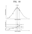
- FIG. 10 illustrates a process of detecting an on-focus position through a defocus amount calculation of one time and performing a three-point interpolation with a driving interval of 6F ⁇ according to one embodiment of the invention.
- the time interval c corresponds to the driving interval of 6F ⁇ .
- the upper view of FIG. 10 is a graph relating to focus signal values depending on focus lens positions (i.e., amounts of defocus).
- the lower view of FIG. 10 is a graph relating to lens driving time depending on focus lens positions. As shown in FIG. 10 , it can be seen that the camera 100 may calculate a focus signal value every time interval c.
- an initial position of the focus lens 115 is position No. 1. While the focus lens 115 is at position No. 1, the camera 100 may calculate a first focus signal value and then move the focus lens 115 to position No. 2. While the focus lens 115 is at position No. 2, the camera 100 may calculate a second focus signal value. At this time, the upper graph of FIG. 10 is depicted for only one frequency band to simplify explanation. Actually, the camera 100 of this embodiment may calculate focus signal values for a plurality of frequency bands, as described above.
- the camera 100 may calculate a focus signal ratio (second focus signal value/first focus signal value) that is a ratio of the second focus signal value to the first focus signal value under state in which the focus lens 115 is at position No. 2. Then, the camera may calculate an amount of defocus at position No. 2 of the focus lens 115 by using the calculated focus signal ratio.
- a focus signal ratio second focus signal value/first focus signal value
- the camera may increase the moving speed depending on the calculated amount of defocus to move the focus lens 115 to position No. 3 toward the on-focus position. Then, the camera 100 may move the focus lens to position No. 4 via position No. 3.
- the camera 100 may detect that the position is near to the on-focus position and perform a three-point interpolation. Specifically, the camera 100 may calculate the focus signal values at position Nos. 4, 5 and 6, respectively, and then calculate a point at which a tangent line of the focus signal value of position No. 4 intersects with a line connecting focus signal values at position Nos. 5 and 6, as shown in the upper graph of FIG. 10 . At this time, it can be seen that the time interval for performing the three-point interpolation is c (i.e., 6F ⁇ ).
- the camera 100 may determine, as an on-focus position, position No. 7 at which the two lines intersect with each other, and finally move the focus lens 115 to position No. 7.
- the camera 100 performs auto focusing.
- the time necessary for focusing is approximately a time interval of 6c.
- the speed at which the focus lens 115 is moved from position No. 2 to position No. 3 is higher than the speed at which the focus lens is moved from position No. 1 to position No. 2.
- the camera 100 may control the moving speed of the focus lens 115 depending on the amount of defocus, it is possible to detect a focus in a shorter time than a case wherein the focus lens 115 is moved at constant speed.
- FIG. 11 illustrates a process of directly moving to a position adjacent to an on-focus position through a defocus amount calculation of one time and performing a three-point interpolation according to one embodiment of the invention.
- FIG. 11 it can be seen in FIG. 11 that the position of the focus lens 115 is directly moved from position No. 2 to position No. 3 that is near to the on-focus position. Also, it can be seen that the camera 100 performs a three-point interpolation by using position Nos. 3, 4 and 5.
- the camera 100 may calculate the amounts of defocus by using the focus signal ratios of two positions and move the focus lens 115 to a position adjacent to the on-focus position with the calculated amounts of defocus.
- the camera 100 may calculate the amounts of defocus by using the focus signal ratios of two positions and move the focus lens 115 to a position adjacent to the on-focus position with the calculated amounts of defocus.
- FIG. 12 illustrates an auto focusing process when an initial position is beyond an on-focus position according to one embodiment of the invention.
- the upper view of FIG. 12 is a graph relating to focus signal values depending on focus lens positions (i.e., amounts of defocus).
- the lower view of FIG. 12 is a graph relating to lens driving time depending on focus lens positions. As shown in FIG. 12 , it can be seen that the camera 100 may calculate a focus signal value every time interval c.
- an initial position of the focus lens 115 is position No. 1. While the focus lens 115 is at position No. 1, the camera 100 may calculate a first focus signal value and then move the focus lens 115 to position No. 2. While the focus lens 115 is at position No. 2, the camera 100 may calculate a second focus signal value. At this time, the upper graph of FIG. 12 is depicted for only one frequency band to simplify explanation. Actually, the camera 100 of this embodiment may calculate focus signal values for a plurality of frequency bands, as described above.
- the camera 100 may calculate a focus signal ratio (second focus signal value/first focus signal value) that is a ratio of the second focus signal value to the first focus signal value under state in which the focus lens 115 is at position No. 2.
- the focus signal value is smaller than 1. This is because the focus signal value of position No. 2 is smaller than that of position No. 1.
- the current moving direction namely, a moving direction from position No. 1 to position No. 2 is a direction away from the on-focus position.
- the camera 100 may move the focus lens 115 to position No. 3 that is in a direction opposite to the current moving direction of the focus lens.
- the camera calculates an amount of defocus at position No. 2 of the focus lens 115 by using the calculated focus signal ratio. At this time, an amount of defocus having a plus value is calculated. Then, the camera 100 may increase the moving speed, taking into consideration the amount of defocus, and move the focus lens 115 to position No. 5 via position Nos. 3 and 4.
- the camera 100 may detect that the position is near to the on-focus position and perform a three-point interpolation. Specifically, the camera 100 may calculate the focus signal values at position Nos. 5, 6 and 7, respectively, and then calculate a point at which a line connecting focus signal values of position Nos. 5 and 6 intersects with a tangent line of the focus signal value of position No. 7, as shown in the upper graph of FIG. 12 . At this time, it can be seen that the time interval necessary for performing the three-point interpolation is c/2.
- the camera 100 may determine, as an on-focus position, position No. 8 at which the two lines intersect with each other, and finally move the focus lens 115 to position No. 8.
- the camera 100 performs auto focusing.
- the camera 100 may change the moving direction of the focus lens 115.
- the time necessary for focusing through the above process is approximately a time interval of 5c.
- the speed at which the focus lens 115 is moved from position No. 2 to position No. 3 is higher than the speed at which the focus lens is moved from position No. 1 to position No. 2.
- the camera 100 may control the moving speed of the focus lens 115 depending on the amount of defocus, it is possible to obtain a focus in a shorter time than a case wherein the focus lens 115 is moved at constant speed.
- the imaging apparatus may include a camcorder, a digital camera and the like.
Landscapes
- Engineering & Computer Science (AREA)
- Physics & Mathematics (AREA)
- Multimedia (AREA)
- Signal Processing (AREA)
- Computer Vision & Pattern Recognition (AREA)
- General Physics & Mathematics (AREA)
- Optics & Photonics (AREA)
- Automatic Focus Adjustment (AREA)
- Studio Devices (AREA)
Applications Claiming Priority (2)
| Application Number | Priority Date | Filing Date | Title |
|---|---|---|---|
| KR1020100025737A KR101085925B1 (ko) | 2010-03-23 | 2010-03-23 | 복수개의 밴드패스필터를 이용하여 자동초점 조절 기능을 수행하는 촬영장치 및 이에 적용되는 자동초점 조절방법 |
| EP11158292 | 2011-03-15 |
Related Parent Applications (2)
| Application Number | Title | Priority Date | Filing Date |
|---|---|---|---|
| EP11158292.0 Division | 2011-03-15 | ||
| EP11158292 Division | 2010-03-23 | 2011-03-15 |
Publications (2)
| Publication Number | Publication Date |
|---|---|
| EP2393280A2 true EP2393280A2 (de) | 2011-12-07 |
| EP2393280A3 EP2393280A3 (de) | 2015-03-25 |
Family
ID=44486129
Family Applications (1)
| Application Number | Title | Priority Date | Filing Date |
|---|---|---|---|
| EP11172934.9A Withdrawn EP2393280A3 (de) | 2010-03-23 | 2011-03-15 | Bilderzeugungsvorichtung mit Autofokusfunktion mit mehreren Bandpassfiltern und Autofokusverfahren dafür |
Country Status (4)
| Country | Link |
|---|---|
| US (1) | US8422878B2 (de) |
| EP (1) | EP2393280A3 (de) |
| KR (1) | KR101085925B1 (de) |
| CN (1) | CN102200674A (de) |
Families Citing this family (11)
| Publication number | Priority date | Publication date | Assignee | Title |
|---|---|---|---|---|
| JP6224995B2 (ja) * | 2013-11-12 | 2017-11-01 | キヤノン株式会社 | 焦点調節装置、撮像装置、焦点調節方法、及びプログラム |
| JP6463053B2 (ja) * | 2014-09-12 | 2019-01-30 | キヤノン株式会社 | 自動合焦装置、および自動合焦方法 |
| CN105430270B (zh) | 2015-12-10 | 2018-11-13 | 浙江宇视科技有限公司 | 一种自动聚焦的方法和装置 |
| US10326925B2 (en) * | 2016-08-10 | 2019-06-18 | Canon Kabushiki Kaisha | Control apparatus for performing focus detection, image capturing apparatus, control method, and non-transitory computer-readable storage medium |
| CN107888819B (zh) * | 2016-09-29 | 2020-07-07 | 华为技术有限公司 | 一种自动聚焦方法及装置 |
| KR102668212B1 (ko) | 2018-09-28 | 2024-05-23 | 삼성전자 주식회사 | 자동 초점 방법 및 이를 수행하는 전자 장치 |
| KR102667875B1 (ko) | 2018-10-29 | 2024-05-22 | 한화비전 주식회사 | 오토 포커스를 수행하는 이미지 촬영 장치 |
| KR102878128B1 (ko) | 2019-03-18 | 2025-10-30 | 삼성전자주식회사 | 자동 초점 조절 기능을 제공하기 위한 전자 장치 및 그 동작 방법 |
| WO2022032611A1 (en) * | 2020-08-14 | 2022-02-17 | Qualcomm Incorporated | Automatic focus control accounting for lens movement during image capture |
| CN114827461A (zh) * | 2022-04-15 | 2022-07-29 | 维沃移动通信(杭州)有限公司 | 拍摄对焦方法、装置和电子设备 |
| JP2025173346A (ja) * | 2024-05-14 | 2025-11-27 | キヤノン株式会社 | 画像処理装置、画像処理方法、及びプログラム |
Citations (1)
| Publication number | Priority date | Publication date | Assignee | Title |
|---|---|---|---|---|
| KR20100025737A (ko) | 2008-08-28 | 2010-03-10 | 주식회사 센트랄 | 프로펠러 샤프트의 센터 베어링용 스토퍼 및 그 제조방법 |
Family Cites Families (13)
| Publication number | Priority date | Publication date | Assignee | Title |
|---|---|---|---|---|
| JP2772079B2 (ja) * | 1989-01-09 | 1998-07-02 | オリンパス光学工業株式会社 | 自動合焦装置 |
| US5083150A (en) * | 1989-03-03 | 1992-01-21 | Olympus Optical Co., Ltd. | Automatic focusing apparatus |
| US5212516A (en) * | 1989-03-28 | 1993-05-18 | Canon Kabushiki Kaisha | Automatic focus adjusting device |
| JPH03182710A (ja) * | 1989-12-12 | 1991-08-08 | Olympus Optical Co Ltd | 焦点検出装置 |
| EP0605240B1 (de) * | 1992-12-28 | 2002-05-02 | Canon Kabushiki Kaisha | Integrierte Einzel-Chip-Schaltung zur Fokussierregelung |
| US5757429A (en) * | 1993-06-17 | 1998-05-26 | Sanyo Electric Co., Ltd. | Automatic focusing apparatus which adjusts the speed of focusing based on a change in the rate of the focus evaluating value |
| KR19990049877A (ko) * | 1997-12-15 | 1999-07-05 | 윤종용 | 카메라시스템의 자동 초점조정장치 및 그에 따른 초점조정방법 |
| CN1249515C (zh) * | 2001-08-10 | 2006-04-05 | 佳能株式会社 | 摄像装置和焦点调节方法 |
| JP2004077959A (ja) * | 2002-08-21 | 2004-03-11 | Nikon Corp | 焦点調節方法およびカメラ |
| JP4646583B2 (ja) * | 2004-09-17 | 2011-03-09 | キヤノン株式会社 | 撮像装置及びその制御方法 |
| JP2007192859A (ja) * | 2006-01-17 | 2007-08-02 | Sony Corp | 合焦制御装置、及び撮像装置 |
| JP5106143B2 (ja) * | 2008-01-21 | 2012-12-26 | キヤノン株式会社 | 自動焦点調整装置及びその自動焦点調整方法 |
| US8049811B2 (en) * | 2009-01-28 | 2011-11-01 | Board Of Regents, The University Of Texas System | Automatic focusing apparatus and method for digital images using automatic filter switching |
-
2010
- 2010-03-23 KR KR1020100025737A patent/KR101085925B1/ko not_active Expired - Fee Related
-
2011
- 2011-03-09 US US13/043,877 patent/US8422878B2/en not_active Expired - Fee Related
- 2011-03-15 EP EP11172934.9A patent/EP2393280A3/de not_active Withdrawn
- 2011-03-23 CN CN2011100701370A patent/CN102200674A/zh active Pending
Patent Citations (1)
| Publication number | Priority date | Publication date | Assignee | Title |
|---|---|---|---|---|
| KR20100025737A (ko) | 2008-08-28 | 2010-03-10 | 주식회사 센트랄 | 프로펠러 샤프트의 센터 베어링용 스토퍼 및 그 제조방법 |
Also Published As
| Publication number | Publication date |
|---|---|
| EP2393280A3 (de) | 2015-03-25 |
| KR101085925B1 (ko) | 2011-11-23 |
| US20110236007A1 (en) | 2011-09-29 |
| KR20110106600A (ko) | 2011-09-29 |
| US8422878B2 (en) | 2013-04-16 |
| CN102200674A (zh) | 2011-09-28 |
Similar Documents
| Publication | Publication Date | Title |
|---|---|---|
| US8422878B2 (en) | Imaging apparatus performing auto focusing function with plurality of band pass filters and auto focusing method applied to the same | |
| US8730373B2 (en) | Image forming apparatus | |
| EP2383597B1 (de) | Linsenvorrichtung | |
| EP1885119B1 (de) | Bildaufnahmevorrichtung und Fokussteuerungsverfahren | |
| US8922703B2 (en) | Focus detection apparatus | |
| JP2008203294A (ja) | 撮像装置 | |
| US20200228719A1 (en) | Focus control apparatus, imaging apparatus, focus control method, and storage medium | |
| JP5845023B2 (ja) | 焦点検出装置及びそれを有するレンズ装置及び撮像装置 | |
| US10326925B2 (en) | Control apparatus for performing focus detection, image capturing apparatus, control method, and non-transitory computer-readable storage medium | |
| JP6987524B2 (ja) | 制御装置、撮像装置、制御方法、プログラム、および、記憶媒体 | |
| JP2014134697A (ja) | 撮像装置 | |
| JP2013221993A (ja) | オートフォーカス制御装置、オートフォーカス制御方法、および撮像装置 | |
| JP2012141436A (ja) | 焦点検出装置およびその制御方法 | |
| JP4574559B2 (ja) | 撮像装置、合焦位置検出装置、及び合焦位置検出方法 | |
| CN108540714B (zh) | 图像捕获装置和系统、图像捕获装置控制方法及存储介质 | |
| JP5300949B2 (ja) | 撮像装置及びフォーカス制御方法 | |
| JP5930979B2 (ja) | 撮像装置 | |
| JP5991743B2 (ja) | 撮像装置および撮像装置の制御方法並びにプログラム | |
| JP7207874B2 (ja) | 制御装置、撮像装置、制御方法、プログラム、および、記憶媒体 | |
| KR20140108015A (ko) | 카메라 모듈 | |
| JP2015022265A (ja) | 焦点検出装置、その制御方法、および制御プログラム、並びに撮像装置 | |
| JP2008026786A (ja) | 撮像装置及びフォーカス制御方法 | |
| JPH01118109A (ja) | 撮影系 |
Legal Events
| Date | Code | Title | Description |
|---|---|---|---|
| AK | Designated contracting states |
Kind code of ref document: A2 Designated state(s): AL AT BE BG CH CY CZ DE DK EE ES FI FR GB GR HR HU IE IS IT LI LT LU LV MC MK MT NL NO PL PT RO RS SE SI SK SM TR |
|
| AX | Request for extension of the european patent |
Extension state: BA ME |
|
| PUAI | Public reference made under article 153(3) epc to a published international application that has entered the european phase |
Free format text: ORIGINAL CODE: 0009012 |
|
| RAP1 | Party data changed (applicant data changed or rights of an application transferred) |
Owner name: SAMSUNG ELECTRONICS CO., LTD. |
|
| PUAL | Search report despatched |
Free format text: ORIGINAL CODE: 0009013 |
|
| AK | Designated contracting states |
Kind code of ref document: A3 Designated state(s): AL AT BE BG CH CY CZ DE DK EE ES FI FR GB GR HR HU IE IS IT LI LT LU LV MC MK MT NL NO PL PT RO RS SE SI SK SM TR |
|
| AX | Request for extension of the european patent |
Extension state: BA ME |
|
| RIC1 | Information provided on ipc code assigned before grant |
Ipc: H04N 5/232 20060101AFI20150218BHEP Ipc: G02B 7/36 20060101ALN20150218BHEP |
|
| STAA | Information on the status of an ep patent application or granted ep patent |
Free format text: STATUS: THE APPLICATION IS DEEMED TO BE WITHDRAWN |
|
| 18D | Application deemed to be withdrawn |
Effective date: 20150926 |