EP2392793A1 - Bolzen und Anordnung zur Befestigung eines Abgaskrümmers an einem Zylinderkopf einer Brennkraftmaschine - Google Patents
Bolzen und Anordnung zur Befestigung eines Abgaskrümmers an einem Zylinderkopf einer Brennkraftmaschine Download PDFInfo
- Publication number
- EP2392793A1 EP2392793A1 EP11160331A EP11160331A EP2392793A1 EP 2392793 A1 EP2392793 A1 EP 2392793A1 EP 11160331 A EP11160331 A EP 11160331A EP 11160331 A EP11160331 A EP 11160331A EP 2392793 A1 EP2392793 A1 EP 2392793A1
- Authority
- EP
- European Patent Office
- Prior art keywords
- bolt
- exhaust manifold
- cylinder head
- nut
- combustion engine
- Prior art date
- Legal status (The legal status is an assumption and is not a legal conclusion. Google has not performed a legal analysis and makes no representation as to the accuracy of the status listed.)
- Granted
Links
Images
Classifications
-
- F—MECHANICAL ENGINEERING; LIGHTING; HEATING; WEAPONS; BLASTING
- F01—MACHINES OR ENGINES IN GENERAL; ENGINE PLANTS IN GENERAL; STEAM ENGINES
- F01N—GAS-FLOW SILENCERS OR EXHAUST APPARATUS FOR MACHINES OR ENGINES IN GENERAL; GAS-FLOW SILENCERS OR EXHAUST APPARATUS FOR INTERNAL-COMBUSTION ENGINES
- F01N13/00—Exhaust or silencing apparatus characterised by constructional features
- F01N13/18—Construction facilitating manufacture, assembly, or disassembly
- F01N13/1805—Fixing exhaust manifolds, exhaust pipes or pipe sections to each other, to engine or to vehicle body
- F01N13/1811—Fixing exhaust manifolds, exhaust pipes or pipe sections to each other, to engine or to vehicle body with means permitting relative movement, e.g. compensation of thermal expansion or vibration
-
- F—MECHANICAL ENGINEERING; LIGHTING; HEATING; WEAPONS; BLASTING
- F01—MACHINES OR ENGINES IN GENERAL; ENGINE PLANTS IN GENERAL; STEAM ENGINES
- F01N—GAS-FLOW SILENCERS OR EXHAUST APPARATUS FOR MACHINES OR ENGINES IN GENERAL; GAS-FLOW SILENCERS OR EXHAUST APPARATUS FOR INTERNAL-COMBUSTION ENGINES
- F01N13/00—Exhaust or silencing apparatus characterised by constructional features
- F01N13/18—Construction facilitating manufacture, assembly, or disassembly
- F01N13/1805—Fixing exhaust manifolds, exhaust pipes or pipe sections to each other, to engine or to vehicle body
-
- F—MECHANICAL ENGINEERING; LIGHTING; HEATING; WEAPONS; BLASTING
- F01—MACHINES OR ENGINES IN GENERAL; ENGINE PLANTS IN GENERAL; STEAM ENGINES
- F01N—GAS-FLOW SILENCERS OR EXHAUST APPARATUS FOR MACHINES OR ENGINES IN GENERAL; GAS-FLOW SILENCERS OR EXHAUST APPARATUS FOR INTERNAL-COMBUSTION ENGINES
- F01N2450/00—Methods or apparatus for fitting, inserting or repairing different elements
- F01N2450/24—Methods or apparatus for fitting, inserting or repairing different elements by bolts, screws, rivets or the like
Definitions
- the invention relates to a bolt for fastening an exhaust manifold to a cylinder head of an internal combustion engine.
- the invention also relates to an arrangement for fastening an exhaust manifold to a cylinder head of an internal combustion engine.
- the attachment of the exhaust manifold on the cylinder head of an internal combustion engine is usually carried out by means bolted to the cylinder head pin bolt, on which the exhaust manifold is placed.
- the exhaust manifold is tightened with flange nuts.
- the nut support on the exhaust manifold can be machined by a face milling (mainly in 6-cylinder in-line engines due to the long thermal expansion caused by the long-build exhaust manifold) or unprocessed (casting surface) are performed.
- the latter solution is applied to smaller exhaust manifolds to save the cost of additional mechanical processing.
- the quality of the nut bearing surface here is subject to a high and fluctuating roughness of the casting surface as well as a Ausformschräge, which is unavoidable due to the preferred division level in the casting process.
- the oblique nut support due the Ausformschräge a large proportion of the emergence of the mother torque. Due to the oblique nut bearing surface takes place after tightening the flange nut an elastic bending of the pin bolt. This results in a higher preload force on one side of the nut support than on the other side. As a result, the frictional forces acting on the nut support surface due to the thermal length expansion of the exhaust manifold also behave differently.
- a modified attachment of an exhaust manifold is shown on a cylinder head by means of a screwed bolt in the cylinder head, which projects through an opening of the manifold flange.
- a spacer sleeve is arranged between the flange and a nut screwed onto the bolt.
- the diameter of the flange opening and the sleeve are larger than the outer diameter of the bolt.
- the sleeve is made of a material whose thermal expansion coefficient is smaller than that of the bolt material.
- the materials for the bolt and for the sleeve are chosen so that the clamping force during operation of the internal combustion engine allows sliding of the flange, which mechanical strains on the exhaust manifold should be avoided.
- the object of the invention is to avoid the above-described possible problems after attachment of an exhaust manifold to a cylinder head of an internal combustion engine or at least reduce and specify the simplest and most cost-effective means that ensure a permanently secure attachment.
- the bolt according to the invention serves for fastening an exhaust manifold to a cylinder head of an internal combustion engine and has an external thread for screwing on a nut, in particular a flange nut.
- the bolt has a central axial portion which has less bending stiffness than adjacent portions of the pin bolt.
- the invention addresses the problems mentioned above, which can lead to a mother turn on a casting-related conditional Ausformschräge the mother support surface by a measure that ensures a more uniform distribution of surface pressure over the circumference of the nut support surface.
- a plastic deformation of the bolt is deliberately sought in order to achieve an adaptation of the position of the nut to the circumstances of the given predetermined mother support surface of the exhaust manifold.
- the inventively provided plastic deformation of the bolt permanently ensures a uniform system of the mother.
- the invention leads to functional, cost and weight advantages.
- the reliability is increased by a possible lack of pressure of the seal between the cylinder head and the exhaust manifold leakage is prevented by the improved inhibition of rotation of the exhaust manifold.
- the invention makes the use of costly, mechanical processing of the cast nut bearing surfaces on the exhaust manifold or subsequently the use superfluous of sliding bars.
- the central axial portion of the bolt has at least one waist.
- the sidecut which alone provides for the lower bending stiffness of this pin portion or at least significantly contributes to this, can already be provided during the production of the bolt or only be formed by subsequent machining of the bolt.
- the waist can be present for example in the form of a material reduction, taper, notch or the like.
- the lower flexural rigidity by forming the middle axial portion of a material having a hardness lower than that of the material of the adjacent portions.
- the invention also relates to an arrangement for fastening an exhaust manifold to a cylinder head of an internal combustion engine with such a bolt.
- the bolt is screwed into the cylinder head and protrudes through an opening formed in the exhaust manifold.
- the exhaust manifold is tightened by a nut screwed onto the bolt.
- the arrangement according to the invention is particularly suitable for exhaust manifolds, in which the surface portion on which the nut rests, relative to a front side of the exhaust manifold or against a cylinder head surface has a slight inclination.
- a geometrically and for the distribution of forces particularly advantageous embodiment results in the event that the central axial portion of the bolt with lower bending stiffness in a region near the end face or near the cylinder head surface is located, preferably within the opening.
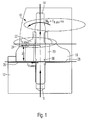
- FIG. 1 is a section of an arrangement for mounting an exhaust manifold 10 to see a cylinder head 12 of an internal combustion engine.
- a pin bolt 14 is screwed into a bore 16 of the cylinder head 12 and projects through an opening 20 formed in a flange 18 of the exhaust manifold 10 (but the opening 20 may also be provided on another flat portion of the exhaust manifold 10).
- the pin bolt 14 has a central axial portion which has one or more sidepieces 30. This portion of the pin bolt 14 has a lower flexural rigidity compared to the adjacent portions. He is in the assembled state of the exhaust manifold 10 in an area near the end face 26 of the flange 18 and near the opposite Cylinder head surface 28, preferably just above it (inside the flange opening 20).
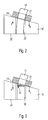
- FIGS. 2 and 3 show in comparison a flange mounting with a conventional pin bolt 14 '( FIG. 2 ) and a flange attachment with a tapered pin bolt 14 (FIG. FIG. 3 , the sidecut itself is not shown separately in the schematic representation).
- FIG. 2 As can be seen, caused by the Ausformschräge the Abgaskrümmerflansches 18 'elastic deformation of the conventional pin bolt 14' to a non-uniform pressure of the nut 22 'on the nut support surface 24'. The uneven surface pressure is symbolized by the different lengths of arrows A 'and B', which represent the local contact force.
- the sidecut of the in FIG. 3 shown pin bolt 14 a plastic deformation of the pin bolt 14, symbolized by the marked area 32, to a limited extent.
- the nut 22 can therefore create a flat surface on the slightly inclined nut support surface 24.
- the waisted pin pin 14 bends permanently and thus ensures a permanently uniform system of the nut 22.
Landscapes
- Engineering & Computer Science (AREA)
- Chemical & Material Sciences (AREA)
- Combustion & Propulsion (AREA)
- Mechanical Engineering (AREA)
- General Engineering & Computer Science (AREA)
- Exhaust Silencers (AREA)
- Cylinder Crankcases Of Internal Combustion Engines (AREA)
Abstract
Description
- Die Erfindung betrifft einen Bolzen zur Befestigung eines Abgaskrümmers an einem Zylinderkopf einer Brennkraftmaschine. Die Erfindung betrifft auch eine Anordnung zur Befestigung eines Abgaskrümmers an einem Zylinderkopf einer Brennkraftmaschine.
- Die Befestigung des Abgaskrümmers am Zylinderkopf einer Brennkraftmaschine erfolgt üblicherweise mittels im Zylinderkopf verschraubter Stiftbolzen, auf welche der Abgaskrümmer aufgesetzt wird. Zur Erreichung der nötigen Dichtungspressung wird der Abgaskrümmer mit Flanschmuttern festgezogen. Die Mutterauflage am Abgaskrümmer kann durch eine Planfräsung bearbeitet werden (vorwiegend bei 6-Zylinder-Reihenmotoren aufgrund der langen thermischen Ausdehnung bedingt durch den lang bauenden Abgaskrümmer) oder auch unbearbeitet (Gussoberfläche) ausgeführt werden. Letztere Lösung wird an kleineren Abgaskrümmern angewandt, um die Kosten für die zusätzliche mechanische Bearbeitung einzusparen. Die Qualität der Mutterauflagefläche ist hier allerdings einer hohen und schwankenden Rauigkeit der Gussoberfläche ebenso wie einer Ausformschräge unterworfen, welche aufgrund der bevorzugten Teilungsebene im Gießprozess unumgänglich ist.
- Aufgrund der thermischen Ausdehnung des Abgaskrümmers im Betrieb der Brennkraftmaschine erfolgt eine Relativbewegung zwischen Zylinderkopf und Abgaskrümmer ebenso wie zwischen Abgaskrümmer und Flanschmutter. Diese Bewegung zwischen Abgaskrümmer und Flanschmutter kann aufgrund der qualitativ schlechteren Auflagequalität bei unbearbeiteten Mutterauflageflächen im zyklischen Motorbetrieb zu einem Aufdrehmoment der Muttern und damit im schlimmsten Fall zu einem Aufdrehen der Muttern führen.
- Neben dem Einfluss unterschiedlicher Reibungskoeffizienten im Bereich der Mutterauflagefläche der Gussoberfläche hat die schräge Mutterauflage aufgrund der Ausformschräge einen großen Anteil an der Entstehung des Mutteraufdrehmoments. Aufgrund der schrägen Mutterauflagefläche erfolgt nach Anzug der Flanschmutter eine elastische Biegung des Stiftbolzens. Dadurch entsteht auf einer Seite der Mutterauflage eine höhere Vorspannkraft als auf der anderen Seite. Dadurch bedingt verhalten sich auch die durch die thermische Längenausdehung des Abgaskrümmers an der Mutterauflagefläche wirkenden Reibungskräfte entsprechend unterschiedlich.
- Zusammengefasst führen folgende Phänomene zu einem erhöhten Mutteraufdrehmoment:
- hohes Unterkopfreibmoment an der Gussoberfläche;
- Relativbewegung an der Mutterauflagefläche zwischen Mutter und Abgaskrümmer;
- schräge Mutterauflage wegen Gussausformschräge am Krümmer;
- unterschiedliche Reibungskoeffizienten an der Mutterauflagefläche (Gussoberfläche).
- Eine Klemmmomenterhöhung bei selbstsichernden Muttern bzw. die Erhöhung der Gewindereibung ist aufgrund der zunehmenden Fressneigung nicht zielführend. Daneben würde dadurch das Aufdrehmoment nur auf den Stiftbolzen verlagert, welcher sich erfahrungsgemäß dann aus dem Aluminiumzylinderkopf herausdreht.
- In der
EP 1 450 018 A1 ist eine modifizierte Befestigung eines Abgaskrümmers an einem Zylinderkopf mittels eines im Zylinderkopf verschraubten Bolzens gezeigt, der durch eine Öffnung des Krümmerflansches ragt. Zwischen dem Flansch und einer auf den Bolzen aufgeschraubten Mutter ist eine Distanzhülse angeordnet. Die Durchmesser der Flanschöffnung und der Hülse sind größer als der Außendurchmesser des Bolzens. Die Hülse besteht aus einem Material, dessen Wärmeausdehnungskoeffizient kleiner als der des Bolzenmaterials ist. Die Materialien für den Bolzen und für die Hülse sind so gewählt, dass die Klemmkraft bei Betrieb der Verbrennungskraftmaschine ein Gleiten des Flansches zulässt, wodurch mechanische Verspannungen am Abgaskrümmer vermieden werden sollen. - Aufgabe der Erfindung ist es, die oben geschilderten möglichen Probleme nach einer Befestigung eines Abgaskrümmers an einem Zylinderkopf einer Brennkraftmaschine zu vermeiden oder wenigstens zu verringern und möglichst einfache und kostengünstige Mittel anzugeben, die eine dauerhaft sichere Befestigung gewährleisten.
- Gelöst wird diese Aufgabe durch einen Befestigungsbolzen mit den Merkmalen des Anspruchs 1 sowie durch eine Anordnung mit den Merkmalen des Anspruchs 4. Vorteilhafte und zweckmäßige Ausgestaltungen des erfindungsgemäßen Befestigungsbolzens bzw. der erfindungsgemäßen Anordnung sind in den zugehörigen Unteransprüchen angegeben.
- Der erfindungsgemäße Bolzen dient zur Befestigung eines Abgaskrümmers an einem Zylinderkopf einer Brennkraftmaschine und hat ein Außengewinde zum Aufschrauben einer Mutter, insbesondere einer Flanschmutter. Der Bolzen weist einen mittleren axialen Abschnitt auf, der im Vergleich zu angrenzenden Abschnitten des Stiftbolzens eine geringere Biegesteifigkeit besitzt.
- Die Erfindung begegnet den eingangs erwähnten Problemen, die insbesondere bei einer gießtechnisch bedingten Ausformschräge der Mutterauflagefläche zu einem Mutteraufdrehen führen können, durch eine Maßnahme, die für eine gleichmäßigere Verteilung der Flächenpressung über dem Umfang der Mutterauflagefläche sorgt. Gemäß der Erfindung wird bewusst eine plastische Verformung des Bolzens angestrebt, um eine Anpassung der Lage der Mutter an die den Umständen entsprechend vorgegebene Mutterauflagefläche des Abgaskrümmers zu erreichen. Die erfindungsgemäß vorgesehene plastische Verformung des Bolzens stellt dauerhaft eine gleichmäßige Anlage der Mutter sicher.
- Die Erfindung führt zu Funktions-, Kosten- und Gewichtsvorteilen. So wird die Betriebssicherheit gesteigert, indem eine durch mangelnde Pressung der Dichtung zwischen Zylinderkopf und Abgaskrümmer mögliche Leckage durch die verbesserte Hemmung eines Aufdrehens der Abgaskrümmerverschraubung verhindert wird. Es entstehen somit kein Abgasgestank, der in den Innenraum gelangen kann, kein kinetischer Abgasenergieverlust und keine Rußverschmutzung des Motorraums bei reduzierter Servicenotwendigkeit. Die Erfindung macht den Einsatz einer kostenaufwendigen, mechanischen Bearbeitung der gegossenen Mutterauflageflächen am Abgaskrümmer bzw. in weiterer Folge den Einsatz von Schiebeleisten überflüssig. Durch Verwendung der erfindungsgemäßen Bolzen kann eventuell auch bei länger bauenden 6-Zylinder-Reihenmotoren auf eine Bearbeitung der Mutterauflageflächen und den Einsatz der Schiebeleisten verzichtet werden. Der Einsatz der erfindungsgemäßen Bolzen verursacht zudem weniger zusätzliches Gewicht als der Einsatz von Schiebleisten.
- Gemäß der bevorzugten Ausführungsform der Erfindung besitzt der mittlere axiale Abschnitt des Bolzens wenigstens eine Taillierung. Die Taillierung, die alleine für die geringere Biegesteifigkeit dieses Bolzenabschnitts sorgt oder zumindest maßgeblich hierzu beiträgt, kann schon bei der Herstellung des Bolzens vorgesehen oder erst durch nachträgliche Bearbeitung des Bolzens gebildet werden. Die Taillierung kann beispielsweise in Form einer Materialreduktion, Verjüngung, Einkerbung oder dergleichen vorliegen.
- Theoretisch ist es auch möglich die geringere Biegesteifigkeit dadurch zu schaffen, dass der mittlere axiale Abschnitt aus einem Material mit einer Härte gebildet ist, die geringer ist als die des Materials der angrenzenden Abschnitte.
- Gegenstand der Erfindung ist auch eine Anordnung zur Befestigung eines Abgaskrümmers an einem Zylinderkopf einer Brennkraftmaschine mit einem solchen Bolzen. Der Bolzen ist in den Zylinderkopf eingeschraubt und ragt durch eine im Abgaskrümmer gebildete Öffnung. Der Abgaskrümmer ist durch eine auf den Bolzen aufgeschraubte Mutter angezogen.
- Die erfindungsgemäße Anordnung eignet sich besonders für Abgaskrümmer, bei denen der Oberflächenabschnitt, auf dem die Mutter aufliegt, gegenüber einer Stirnseite des Abgaskrümmers oder gegenüber einer Zylinderkopfoberfläche eine geringfügige Neigung aufweist.
- Eine geometrisch und für die Kräfteverteilung besonders vorteilhafte Ausgestaltung ergibt sich für den Fall, dass sich der mittlere axiale Abschnitt des Bolzens mit geringerer Biegesteifigkeit in einem Bereich nahe der Stirnseite oder nahe der Zylinderkopfoberfläche befindet, vorzugsweise innerhalb der Öffnung.
- Im Gegensatz zu einer unerwünschten elastischen Verformung des Bolzens bei der Montage und/oder bedingt durch unterschiedliche Längenausdehnungen des Abgaskrümmers und des Zylinderkopfs während des Betriebs der Brennkraftmaschine wird bei der erfindungsgemäßen Anordnung bewusst eine bleibend Verformung des mittleren axialen Abschnitts des Bolzens nach einem Erstanzug der Mutter angestrebt, um dadurch mechanische Verspannungen gezielt zu vermeiden.
- Weitere Merkmale und Vorteile der Erfindung ergeben sich aus der nachfolgenden Beschreibung und aus den beigefügten Zeichnungen, auf die Bezug genommen wird. In den Zeichnungen zeigen:
-
Figur 1 einen Ausschnitt einer Anordnung zur Befestigung eines Abgaskrümmers an einem Zylinderkopf; -
Figur 2 eine schematische Ansicht einer Flanschbefestigung mit einem herkömmlichen Bolzen; und -
Figur 3 eine schematische Ansicht einer Flanschbefestigung mit einem erfindungsgemäßen Bolzen. - In
Figur 1 ist ein Ausschnitt einer Anordnung zur Befestigung eines Abgaskrümmers 10 an einem Zylinderkopf 12 einer Brennkraftmaschine zu sehen. Ein Stiftbolzen 14 ist in eine Bohrung 16 des Zylinderkopfs 12 geschraubt und ragt durch eine in einem Flansch 18 des Abgaskrümmers 10 gebildete Öffnung 20 (die Öffnung 20 kann aber auch an einem anderen flachen Abschnitt des Abgaskrümmers 10 vorgesehen sein). - Mittels einer auf ein Außengewinde des Stiftbolzens 14 aufgeschraubten Mutter 22, insbesondere einer Flanschmutter, wird der Abgaskrümmer 10 festgezogen. Der Oberflächenabschnitt 24 des Flansches 18, auf der die Mutter 22 aufliegt (Mutterauflagefläche), weist gegenüber der ebenen Stirnseite 26 des Flanschs 18 bzw. gegenüber der ebenen Zylinderkopfoberfläche 28 eine geringfügige Neigung auf, die durch die gießtechnische Herstellung des Abgaskrümmers 10 bedingt ist (sog. Ausformschräge).
- Der Stiftbolzen 14 weist einen mittleren axialen Abschnitt auf, der eine oder mehrere Taillierungen 30 besitzt. Dieser Abschnitt des Stiftbolzens 14 hat im Vergleich zu den angrenzenden Abschnitten eine geringere Biegesteifigkeit. Er befindet sich im montierten Zustand des Abgaskrümmers 10 in einem Bereich nahe der Stirnseite 26 des Flanschs 18 bzw. nahe der gegenüberliegenden Zylinderkopfoberfläche 28, vorzugsweise knapp darüber (innerhalb der Flanschöffnung 20).
- Die
Figuren 2 und 3 zeigen im Vergleich eine Flanschbefestigung mit einem herkömmlichen Stiftbolzen 14' (Figur 2 ) und eine Flanschbefestigung mit einem taillierten Stiftbolzen 14 (Figur 3 , die Taillierung selbst ist in der schematischen Darstellung nicht gesondert dargestellt). Wie inFigur 2 zu sehen ist, führt die durch die Ausformschräge des Abgaskrümmerflansches 18' bedingte elastische Verformung des herkömmlichen Stiftbolzens 14' zu einer ungleichmäßigen Pressung der Mutter 22' an der Mutterauflagefläche 24'. Die ungleichmäßige Flächenpressung ist symbolisiert durch die unterschiedlich langen Pfeile A' und B', die die lokale Anpresskraft repräsentieren. - Dagegen lässt die Taillierung des in
Figur 3 gezeigten Stiftbolzens 14 eine plastische Deformation des Stiftbolzens 14, symbolisiert durch den markierten Bereich 32, in einem begrenzten Ausmaß zu. Beim Erstanzug der Mutter 22 während der Abgaskrümmermontage kann sich die Mutter 22 deshalb flächig an der leicht schrägen Mutterauflagefläche 24 anlegen. Der taillierte Stiftbolzen 14 verbiegt sich bleibend und stellt so eine dauerhaft gleichmäßige Anlage der Mutter 22 sicher. - Aufgrund der gleichmäßigen Flächenpressung (vgl. Pfeile A und B) ergeben sich wiederum gleichmäßige Reibkräfte um den Umfang der Mutterauflagefläche 24, sodass in der Folge kein Mutteraufdrehmoment erzeugt wird. Selbst im Falle einer rein elastischen Verformung erlaubt die geringere Biegesteifigkeit des taillierten Abschnitts des Stiftbolzens 14 durch die erleichterte Biegung bereits eine Vergleichmäßigung der Pressungsverteilung und damit ein geringeres Mutteraufdrehmoment bei Verschiebung des Abgaskrümmers unter der Mutter 22.
- Die Anordnung zur Befestigung des Abgaskrümmers 10 am Zylinderkopf 12 wurde am Beispiel einer einzelnen Befestigungsstelle beschrieben, sie umfasst natürlich mehrere derartige Befestigungsstellen mit taillierten Stiftbolzen 14.
-
- 10
- Abgaskrümmer
- 12
- Zylinderkopf
- 14, 14'
- Stiftbolzen
- 16
- Bohrung
- 18, 18'
- Flansch
- 20, 20'
- Öffnung
- 22, 22'
- Mutter
- 24, 24'
- Mutterauflagefläche
- 26, 26'
- Stirnseite des Flanschs
- 28
- Zylinderkopfoberfläche
- 30
- Taillierung
- 32
- plastisch deformierter Bereich
Claims (7)
- Bolzen (14) zur Befestigung eines Abgaskrümmers (10) an einem Zylinderkopf (12) einer Brennkraftmaschine, mit einem Außengewinde zum Aufschrauben einer Mutter (22), insbesondere einer Flanschmutter,
gekennzeichnet durch einen mittleren axialen Abschnitt, der im Vergleich zu angrenzenden Abschnitten des Stiftbolzens (14) eine geringere Biegesteifigkeit besitzt. - Bolzen nach Anspruch 1, dadurch gekennzeichnet, dass der mittlere axiale Abschnitt wenigstens eine Taillierung (30) besitzt.
- Bolzen nach Anspruch 1 oder 2, dadurch gekennzeichnet, dass der mittlere axiale Abschnitt aus einem Material mit einer Härte gebildet ist, die geringer ist als die des Materials der angrenzenden Abschnitte.
- Anordnung zur Befestigung eines Abgaskrümmers (10) an einem Zylinderkopf (12) einer Brennkraftmaschine, gekennzeichnet durch einen Bolzen (14) nach einem der vorhergehenden Ansprüche, wobei der Bolzen (14) in den Zylinderkopf (12) eingeschraubt ist und durch eine im Abgaskrümmer (10) gebildete Öffnung (20) ragt, und wobei der Abgaskrümmer (10) durch eine auf den Bolzen (14) aufgeschraubte Mutter (22) angezogen ist.
- Anordnung nach Anspruch 4, dadurch gekennzeichnet, dass der Oberflächenabschnitt (24) des Abgaskrümmers (10), auf dem die Mutter (22) aufliegt, gegenüber einer Stirnseite (26) des Abgaskrümmers (10) oder gegenüber einer Zylinderkopfoberfläche (28) eine geringfügige Neigung aufweist.
- Anordnung nach Anspruch 5, dadurch gekennzeichnet, dass sich der mittlere axiale Abschnitt des Bolzens (14) mit geringerer Biegesteifigkeit in einem Bereich nahe der Stirnseite (26) oder nahe der Zylinderkopfoberfläche (28) befindet, vorzugsweise innerhalb der Öffnung (20).
- Anordnung nach einem der Ansprüche 4 bis 6, dadurch gekennzeichnet, dass der mittlere axiale Abschnitt des Bolzens (14) nach einem Erstanzug der Mutter (22) bleibend verformt ist.
Applications Claiming Priority (1)
| Application Number | Priority Date | Filing Date | Title |
|---|---|---|---|
| DE102010022540A DE102010022540A1 (de) | 2010-06-02 | 2010-06-02 | Bolzen und Anordnung zur Befestigung eines Abgaskrümmers an einem Zylinderkopf einer Brennkraftmaschine |
Publications (2)
| Publication Number | Publication Date |
|---|---|
| EP2392793A1 true EP2392793A1 (de) | 2011-12-07 |
| EP2392793B1 EP2392793B1 (de) | 2013-05-01 |
Family
ID=44515113
Family Applications (1)
| Application Number | Title | Priority Date | Filing Date |
|---|---|---|---|
| EP20110160331 Not-in-force EP2392793B1 (de) | 2010-06-02 | 2011-03-30 | Anordnung zur Befestigung eines Abgaskrümmers an einem Zylinderkopf einer Brennkraftmaschine |
Country Status (2)
| Country | Link |
|---|---|
| EP (1) | EP2392793B1 (de) |
| DE (1) | DE102010022540A1 (de) |
Citations (3)
| Publication number | Priority date | Publication date | Assignee | Title |
|---|---|---|---|---|
| EP1450018A1 (de) | 2003-02-18 | 2004-08-25 | J. Eberspächer GmbH & Co. KG | Befestigungssystem und Verfahren zum Festlegen eines Auspuffkrümmers an einer Verbrennungskraftmaschine, und Verbrennungskraftmaschinenanordnung |
| FR2916182A3 (fr) * | 2007-05-15 | 2008-11-21 | Renault Sas | Agencement pour le maintien en position de montage d'un turbocompresseur suspendu. |
| FR2925588A1 (fr) * | 2007-12-21 | 2009-06-26 | Renault Sas | Dispositif de fixation d'un collecteur d'echappement |
Family Cites Families (2)
| Publication number | Priority date | Publication date | Assignee | Title |
|---|---|---|---|---|
| DE3119192A1 (de) * | 1981-05-14 | 1982-12-09 | Klöckner-Humboldt-Deutz AG, 5000 Köln | Zentrierbolzen fuer flanschverbindungen |
| JPH07310540A (ja) * | 1994-05-13 | 1995-11-28 | Mitsubishi Motors Corp | 内燃機関の排気装置 |
-
2010
- 2010-06-02 DE DE102010022540A patent/DE102010022540A1/de not_active Withdrawn
-
2011
- 2011-03-30 EP EP20110160331 patent/EP2392793B1/de not_active Not-in-force
Patent Citations (3)
| Publication number | Priority date | Publication date | Assignee | Title |
|---|---|---|---|---|
| EP1450018A1 (de) | 2003-02-18 | 2004-08-25 | J. Eberspächer GmbH & Co. KG | Befestigungssystem und Verfahren zum Festlegen eines Auspuffkrümmers an einer Verbrennungskraftmaschine, und Verbrennungskraftmaschinenanordnung |
| FR2916182A3 (fr) * | 2007-05-15 | 2008-11-21 | Renault Sas | Agencement pour le maintien en position de montage d'un turbocompresseur suspendu. |
| FR2925588A1 (fr) * | 2007-12-21 | 2009-06-26 | Renault Sas | Dispositif de fixation d'un collecteur d'echappement |
Also Published As
| Publication number | Publication date |
|---|---|
| DE102010022540A1 (de) | 2011-12-08 |
| EP2392793B1 (de) | 2013-05-01 |
Similar Documents
| Publication | Publication Date | Title |
|---|---|---|
| EP1223337B1 (de) | Geraeuschreduzierende Anordnung von Unterlegscheiben unter einer Einspritzduese | |
| DE102009015827B4 (de) | Lageranordnung zur drehbaren Lagerung eines Maschinenteils | |
| DE102009053102A1 (de) | Axiallageranordnung für eine Welle eines Turboladers | |
| EP2604816A1 (de) | Welle-/Lageranordnung | |
| DE102011087683A1 (de) | Korrosionsbeständige Schraube, Verwendung einer derartigen Schraube in einer korrosiven Umgebung und Verfahren zur Herstellung einer solchen Schraube | |
| EP2392793B1 (de) | Anordnung zur Befestigung eines Abgaskrümmers an einem Zylinderkopf einer Brennkraftmaschine | |
| DE102015209642A1 (de) | Schraubverbindung und Läufer für einen Abgasturbolader | |
| WO2010063272A1 (de) | Montagevorrichtung mit einem zuganker und korrespondierendes verfahren für ein rotorsystem einer axial-strömungsmaschine | |
| DE102015209641A1 (de) | Schraubverbindung und Läufer für einen Abgasturbolader | |
| EP2053235B1 (de) | Brennkraftmaschine mit Kraftstoffinjektoren | |
| EP2407684B1 (de) | Aggregatelager | |
| WO2019166191A1 (de) | Lenksystem-wellenlagerungsbaugruppe, lenksystem sowie verfahren zur herstellung eines lenksystems | |
| EP2798231B1 (de) | Abstandselement und Verfahren zur Vor- und Endmontage | |
| DE102010018345A1 (de) | Baugruppe zur Befestigung eines Abgaskrümmers an einem Zylinderkopf sowie Motoreinheit | |
| DE102011117942A1 (de) | Gehäuse für eine Verbrennungskraftmaschine | |
| DE102006050132B3 (de) | Statisch überbestimmte Lagerung eines Antriebsaggregats eines Kraftfahrzeugs | |
| DE102012011322A1 (de) | Befestigungsanordnung eines Lagerelements an einem Kurbelgehäuse sowie Verfahren zum Befestigen eines Lagerelements an einem Kurbelgehäuse | |
| DE102009038079A1 (de) | Kraftstoffzufuhrvorrichtung sowie Verfahren zum Herstellen einer Kraftstoffzufuhrvorrichtung | |
| DE102022003616A1 (de) | Vorrichtung zum Transportschutz eines Entkopplungselements für einen Abgasleitungsstrang | |
| DE400490C (de) | Verbindung zweier Lagervorrichtungen, von welchen fuer gewoehnlich die eine entweder allein oder doch hauptsaechlich als solche wirksam ist | |
| DE102013009756A1 (de) | Befestigungsanordnung von Lagerelementen an einem Kurbelgehäuse für eine Hubkolben-Verbrennungskraftmaschine | |
| EP4530493A1 (de) | Befestigungssystem zur vibrationsgedämpften befestigung zweier bauteile sowie daraus aufgebaute baugruppe | |
| EP2333358B1 (de) | Befestigungsvorrichtung | |
| DE102013012156A1 (de) | Spanneinrichtung zum Verspannen einer Mehrzahl von Bauteilen | |
| DE102021001648A1 (de) | Befestigungselnrichtung für einen lnjektor einer Verbrennungskraftmaschine, insbesondere eines Kraftfahrzeugs |
Legal Events
| Date | Code | Title | Description |
|---|---|---|---|
| AK | Designated contracting states |
Kind code of ref document: A1 Designated state(s): AL AT BE BG CH CY CZ DE DK EE ES FI FR GB GR HR HU IE IS IT LI LT LU LV MC MK MT NL NO PL PT RO RS SE SI SK SM TR |
|
| AX | Request for extension of the european patent |
Extension state: BA ME |
|
| PUAI | Public reference made under article 153(3) epc to a published international application that has entered the european phase |
Free format text: ORIGINAL CODE: 0009012 |
|
| 17P | Request for examination filed |
Effective date: 20120418 |
|
| 17Q | First examination report despatched |
Effective date: 20120625 |
|
| GRAP | Despatch of communication of intention to grant a patent |
Free format text: ORIGINAL CODE: EPIDOSNIGR1 |
|
| GRAS | Grant fee paid |
Free format text: ORIGINAL CODE: EPIDOSNIGR3 |
|
| GRAA | (expected) grant |
Free format text: ORIGINAL CODE: 0009210 |
|
| AK | Designated contracting states |
Kind code of ref document: B1 Designated state(s): AL AT BE BG CH CY CZ DE DK EE ES FI FR GB GR HR HU IE IS IT LI LT LU LV MC MK MT NL NO PL PT RO RS SE SI SK SM TR |
|
| REG | Reference to a national code |
Ref country code: GB Ref legal event code: FG4D Free format text: NOT ENGLISH |
|
| REG | Reference to a national code |
Ref country code: CH Ref legal event code: EP Ref country code: AT Ref legal event code: REF Ref document number: 610094 Country of ref document: AT Kind code of ref document: T Effective date: 20130515 |
|
| REG | Reference to a national code |
Ref country code: IE Ref legal event code: FG4D Free format text: LANGUAGE OF EP DOCUMENT: GERMAN |
|
| REG | Reference to a national code |
Ref country code: DE Ref legal event code: R096 Ref document number: 502011000684 Country of ref document: DE Effective date: 20130704 |
|
| REG | Reference to a national code |
Ref country code: NL Ref legal event code: VDEP Effective date: 20130501 |
|
| REG | Reference to a national code |
Ref country code: LT Ref legal event code: MG4D |
|
| PG25 | Lapsed in a contracting state [announced via postgrant information from national office to epo] |
Ref country code: PT Free format text: LAPSE BECAUSE OF FAILURE TO SUBMIT A TRANSLATION OF THE DESCRIPTION OR TO PAY THE FEE WITHIN THE PRESCRIBED TIME-LIMIT Effective date: 20130902 Ref country code: SI Free format text: LAPSE BECAUSE OF FAILURE TO SUBMIT A TRANSLATION OF THE DESCRIPTION OR TO PAY THE FEE WITHIN THE PRESCRIBED TIME-LIMIT Effective date: 20130501 Ref country code: FI Free format text: LAPSE BECAUSE OF FAILURE TO SUBMIT A TRANSLATION OF THE DESCRIPTION OR TO PAY THE FEE WITHIN THE PRESCRIBED TIME-LIMIT Effective date: 20130501 Ref country code: ES Free format text: LAPSE BECAUSE OF FAILURE TO SUBMIT A TRANSLATION OF THE DESCRIPTION OR TO PAY THE FEE WITHIN THE PRESCRIBED TIME-LIMIT Effective date: 20130812 Ref country code: SE Free format text: LAPSE BECAUSE OF FAILURE TO SUBMIT A TRANSLATION OF THE DESCRIPTION OR TO PAY THE FEE WITHIN THE PRESCRIBED TIME-LIMIT Effective date: 20130501 Ref country code: GR Free format text: LAPSE BECAUSE OF FAILURE TO SUBMIT A TRANSLATION OF THE DESCRIPTION OR TO PAY THE FEE WITHIN THE PRESCRIBED TIME-LIMIT Effective date: 20130802 Ref country code: IS Free format text: LAPSE BECAUSE OF FAILURE TO SUBMIT A TRANSLATION OF THE DESCRIPTION OR TO PAY THE FEE WITHIN THE PRESCRIBED TIME-LIMIT Effective date: 20130901 Ref country code: NO Free format text: LAPSE BECAUSE OF FAILURE TO SUBMIT A TRANSLATION OF THE DESCRIPTION OR TO PAY THE FEE WITHIN THE PRESCRIBED TIME-LIMIT Effective date: 20130801 Ref country code: LT Free format text: LAPSE BECAUSE OF FAILURE TO SUBMIT A TRANSLATION OF THE DESCRIPTION OR TO PAY THE FEE WITHIN THE PRESCRIBED TIME-LIMIT Effective date: 20130501 |
|
| PG25 | Lapsed in a contracting state [announced via postgrant information from national office to epo] |
Ref country code: CY Free format text: LAPSE BECAUSE OF FAILURE TO SUBMIT A TRANSLATION OF THE DESCRIPTION OR TO PAY THE FEE WITHIN THE PRESCRIBED TIME-LIMIT Effective date: 20130501 Ref country code: PL Free format text: LAPSE BECAUSE OF FAILURE TO SUBMIT A TRANSLATION OF THE DESCRIPTION OR TO PAY THE FEE WITHIN THE PRESCRIBED TIME-LIMIT Effective date: 20130501 Ref country code: BG Free format text: LAPSE BECAUSE OF FAILURE TO SUBMIT A TRANSLATION OF THE DESCRIPTION OR TO PAY THE FEE WITHIN THE PRESCRIBED TIME-LIMIT Effective date: 20130801 Ref country code: RS Free format text: LAPSE BECAUSE OF FAILURE TO SUBMIT A TRANSLATION OF THE DESCRIPTION OR TO PAY THE FEE WITHIN THE PRESCRIBED TIME-LIMIT Effective date: 20130501 Ref country code: HR Free format text: LAPSE BECAUSE OF FAILURE TO SUBMIT A TRANSLATION OF THE DESCRIPTION OR TO PAY THE FEE WITHIN THE PRESCRIBED TIME-LIMIT Effective date: 20130501 |
|
| PG25 | Lapsed in a contracting state [announced via postgrant information from national office to epo] |
Ref country code: LV Free format text: LAPSE BECAUSE OF FAILURE TO SUBMIT A TRANSLATION OF THE DESCRIPTION OR TO PAY THE FEE WITHIN THE PRESCRIBED TIME-LIMIT Effective date: 20130501 |
|
| PG25 | Lapsed in a contracting state [announced via postgrant information from national office to epo] |
Ref country code: CZ Free format text: LAPSE BECAUSE OF FAILURE TO SUBMIT A TRANSLATION OF THE DESCRIPTION OR TO PAY THE FEE WITHIN THE PRESCRIBED TIME-LIMIT Effective date: 20130501 Ref country code: DK Free format text: LAPSE BECAUSE OF FAILURE TO SUBMIT A TRANSLATION OF THE DESCRIPTION OR TO PAY THE FEE WITHIN THE PRESCRIBED TIME-LIMIT Effective date: 20130501 Ref country code: SK Free format text: LAPSE BECAUSE OF FAILURE TO SUBMIT A TRANSLATION OF THE DESCRIPTION OR TO PAY THE FEE WITHIN THE PRESCRIBED TIME-LIMIT Effective date: 20130501 Ref country code: EE Free format text: LAPSE BECAUSE OF FAILURE TO SUBMIT A TRANSLATION OF THE DESCRIPTION OR TO PAY THE FEE WITHIN THE PRESCRIBED TIME-LIMIT Effective date: 20130501 |
|
| PG25 | Lapsed in a contracting state [announced via postgrant information from national office to epo] |
Ref country code: NL Free format text: LAPSE BECAUSE OF FAILURE TO SUBMIT A TRANSLATION OF THE DESCRIPTION OR TO PAY THE FEE WITHIN THE PRESCRIBED TIME-LIMIT Effective date: 20130501 Ref country code: RO Free format text: LAPSE BECAUSE OF FAILURE TO SUBMIT A TRANSLATION OF THE DESCRIPTION OR TO PAY THE FEE WITHIN THE PRESCRIBED TIME-LIMIT Effective date: 20130501 |
|
| PLBE | No opposition filed within time limit |
Free format text: ORIGINAL CODE: 0009261 |
|
| STAA | Information on the status of an ep patent application or granted ep patent |
Free format text: STATUS: NO OPPOSITION FILED WITHIN TIME LIMIT |
|
| 26N | No opposition filed |
Effective date: 20140204 |
|
| REG | Reference to a national code |
Ref country code: DE Ref legal event code: R097 Ref document number: 502011000684 Country of ref document: DE Effective date: 20140204 |
|
| PG25 | Lapsed in a contracting state [announced via postgrant information from national office to epo] |
Ref country code: LU Free format text: LAPSE BECAUSE OF FAILURE TO SUBMIT A TRANSLATION OF THE DESCRIPTION OR TO PAY THE FEE WITHIN THE PRESCRIBED TIME-LIMIT Effective date: 20140330 |
|
| REG | Reference to a national code |
Ref country code: CH Ref legal event code: PL |
|
| REG | Reference to a national code |
Ref country code: IE Ref legal event code: MM4A |
|
| PG25 | Lapsed in a contracting state [announced via postgrant information from national office to epo] |
Ref country code: IE Free format text: LAPSE BECAUSE OF NON-PAYMENT OF DUE FEES Effective date: 20140330 Ref country code: CH Free format text: LAPSE BECAUSE OF NON-PAYMENT OF DUE FEES Effective date: 20140331 Ref country code: LI Free format text: LAPSE BECAUSE OF NON-PAYMENT OF DUE FEES Effective date: 20140331 |
|
| PG25 | Lapsed in a contracting state [announced via postgrant information from national office to epo] |
Ref country code: MT Free format text: LAPSE BECAUSE OF FAILURE TO SUBMIT A TRANSLATION OF THE DESCRIPTION OR TO PAY THE FEE WITHIN THE PRESCRIBED TIME-LIMIT Effective date: 20130501 |
|
| REG | Reference to a national code |
Ref country code: FR Ref legal event code: PLFP Year of fee payment: 6 |
|
| PG25 | Lapsed in a contracting state [announced via postgrant information from national office to epo] |
Ref country code: SM Free format text: LAPSE BECAUSE OF FAILURE TO SUBMIT A TRANSLATION OF THE DESCRIPTION OR TO PAY THE FEE WITHIN THE PRESCRIBED TIME-LIMIT Effective date: 20130501 |
|
| PG25 | Lapsed in a contracting state [announced via postgrant information from national office to epo] |
Ref country code: MC Free format text: LAPSE BECAUSE OF FAILURE TO SUBMIT A TRANSLATION OF THE DESCRIPTION OR TO PAY THE FEE WITHIN THE PRESCRIBED TIME-LIMIT Effective date: 20130501 |
|
| PG25 | Lapsed in a contracting state [announced via postgrant information from national office to epo] |
Ref country code: TR Free format text: LAPSE BECAUSE OF FAILURE TO SUBMIT A TRANSLATION OF THE DESCRIPTION OR TO PAY THE FEE WITHIN THE PRESCRIBED TIME-LIMIT Effective date: 20130501 Ref country code: HU Free format text: LAPSE BECAUSE OF FAILURE TO SUBMIT A TRANSLATION OF THE DESCRIPTION OR TO PAY THE FEE WITHIN THE PRESCRIBED TIME-LIMIT; INVALID AB INITIO Effective date: 20110330 |
|
| REG | Reference to a national code |
Ref country code: FR Ref legal event code: PLFP Year of fee payment: 7 |
|
| REG | Reference to a national code |
Ref country code: AT Ref legal event code: MM01 Ref document number: 610094 Country of ref document: AT Kind code of ref document: T Effective date: 20160330 |
|
| PG25 | Lapsed in a contracting state [announced via postgrant information from national office to epo] |
Ref country code: BE Free format text: LAPSE BECAUSE OF NON-PAYMENT OF DUE FEES Effective date: 20140331 |
|
| PG25 | Lapsed in a contracting state [announced via postgrant information from national office to epo] |
Ref country code: AT Free format text: LAPSE BECAUSE OF NON-PAYMENT OF DUE FEES Effective date: 20160330 |
|
| REG | Reference to a national code |
Ref country code: FR Ref legal event code: PLFP Year of fee payment: 8 |
|
| PG25 | Lapsed in a contracting state [announced via postgrant information from national office to epo] |
Ref country code: MK Free format text: LAPSE BECAUSE OF FAILURE TO SUBMIT A TRANSLATION OF THE DESCRIPTION OR TO PAY THE FEE WITHIN THE PRESCRIBED TIME-LIMIT Effective date: 20130501 |
|
| PG25 | Lapsed in a contracting state [announced via postgrant information from national office to epo] |
Ref country code: AL Free format text: LAPSE BECAUSE OF FAILURE TO SUBMIT A TRANSLATION OF THE DESCRIPTION OR TO PAY THE FEE WITHIN THE PRESCRIBED TIME-LIMIT Effective date: 20130501 |
|
| PGFP | Annual fee paid to national office [announced via postgrant information from national office to epo] |
Ref country code: GB Payment date: 20220324 Year of fee payment: 12 Ref country code: DE Payment date: 20220316 Year of fee payment: 12 |
|
| PGFP | Annual fee paid to national office [announced via postgrant information from national office to epo] |
Ref country code: FR Payment date: 20220322 Year of fee payment: 12 |
|
| PGFP | Annual fee paid to national office [announced via postgrant information from national office to epo] |
Ref country code: IT Payment date: 20220331 Year of fee payment: 12 |
|
| P01 | Opt-out of the competence of the unified patent court (upc) registered |
Effective date: 20230502 |
|
| REG | Reference to a national code |
Ref country code: DE Ref legal event code: R119 Ref document number: 502011000684 Country of ref document: DE |
|
| GBPC | Gb: european patent ceased through non-payment of renewal fee |
Effective date: 20230330 |
|
| PG25 | Lapsed in a contracting state [announced via postgrant information from national office to epo] |
Ref country code: GB Free format text: LAPSE BECAUSE OF NON-PAYMENT OF DUE FEES Effective date: 20230330 |
|
| PG25 | Lapsed in a contracting state [announced via postgrant information from national office to epo] |
Ref country code: GB Free format text: LAPSE BECAUSE OF NON-PAYMENT OF DUE FEES Effective date: 20230330 Ref country code: FR Free format text: LAPSE BECAUSE OF NON-PAYMENT OF DUE FEES Effective date: 20230331 Ref country code: DE Free format text: LAPSE BECAUSE OF NON-PAYMENT OF DUE FEES Effective date: 20231003 |
|
| PG25 | Lapsed in a contracting state [announced via postgrant information from national office to epo] |
Ref country code: IT Free format text: LAPSE BECAUSE OF NON-PAYMENT OF DUE FEES Effective date: 20230330 |