EP2392789A1 - Elektrohydraulische Ventilsteuerung - Google Patents
Elektrohydraulische Ventilsteuerung Download PDFInfo
- Publication number
- EP2392789A1 EP2392789A1 EP11163107A EP11163107A EP2392789A1 EP 2392789 A1 EP2392789 A1 EP 2392789A1 EP 11163107 A EP11163107 A EP 11163107A EP 11163107 A EP11163107 A EP 11163107A EP 2392789 A1 EP2392789 A1 EP 2392789A1
- Authority
- EP
- European Patent Office
- Prior art keywords
- valve
- hydraulic
- hydraulic valve
- pressure
- connection
- Prior art date
- Legal status (The legal status is an assumption and is not a legal conclusion. Google has not performed a legal analysis and makes no representation as to the accuracy of the status listed.)
- Granted
Links
Images
Classifications
-
- F—MECHANICAL ENGINEERING; LIGHTING; HEATING; WEAPONS; BLASTING
- F01—MACHINES OR ENGINES IN GENERAL; ENGINE PLANTS IN GENERAL; STEAM ENGINES
- F01L—CYCLICALLY OPERATING VALVES FOR MACHINES OR ENGINES
- F01L9/00—Valve-gear or valve arrangements actuated non-mechanically
- F01L9/10—Valve-gear or valve arrangements actuated non-mechanically by fluid means, e.g. hydraulic
- F01L9/11—Valve-gear or valve arrangements actuated non-mechanically by fluid means, e.g. hydraulic in which the action of a cam is being transmitted to a valve by a liquid column
- F01L9/12—Valve-gear or valve arrangements actuated non-mechanically by fluid means, e.g. hydraulic in which the action of a cam is being transmitted to a valve by a liquid column with a liquid chamber between a piston actuated by a cam and a piston acting on a valve stem
- F01L9/14—Valve-gear or valve arrangements actuated non-mechanically by fluid means, e.g. hydraulic in which the action of a cam is being transmitted to a valve by a liquid column with a liquid chamber between a piston actuated by a cam and a piston acting on a valve stem the volume of the chamber being variable, e.g. for varying the lift or the timing of a valve
Definitions
- the variability of the timing and the maximum stroke of the gas exchange valve is achieved in that a partial volume of acting as a so-called hydraulic linkage pressure chamber is continuously adjustable with open first hydraulic valve in the pressure relief chamber and accordingly the camshaft predetermined cam lift completely, partially or even not transferred to the gas exchange valve.
- the present invention is based on the object to provide a valve control of the type mentioned in an alternative embodiment.
- the second hydraulic valve should be arranged in the control line, that in case of incorrectly open first hydraulic valve, the connection from the pressure chamber to the hydraulic medium supply made and the connection is interrupted by the hydraulic fluid supply to the pressure relief space.
- connection from the hydraulic fluid supply remains with the first hydraulic valve is independent of the switching position of the second hydraulic valve.
- the tracking of leakage balancing hydraulic fluid from the hydraulic fluid supply in the pressure chamber is therefore not affected by the switching position of the second hydraulic valve. Consequently, the bypass line required in the cited prior art, which bypasses the two hydraulic valves connected in series there downstream of the hydraulic fluid supply and produces a direct connection controlled by a check valve from the hydraulic fluid supply to the pressure chamber, can be dispensed with.
- the second hydraulic valve is also electrically energized, unlike the first hydraulic valve, however, be designed to be normally closed, in order to ensure the necessary emergency running properties of the internal combustion engine in the event of a power failure at both hydraulic valves.
- the second hydraulic valve can also be provided in hydraulic or pneumatic pressure-actuated design and the two variants without pressure open or unpressurized closed.
- the pneumatic valve design can be particularly advantageous in marine engines, which are equipped for starting the engine with a compressed air supply.
- a manually operable second hydraulic valve can also be used.
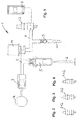
- FIG. 1 shows the essential components of an electro-hydraulic valve control 1 according to the invention for the variable actuation of a gas exchange valve 2 of an internal combustion engine based on a hydraulic circuit diagram. Shown are a master piston 3, which is driven by a cam 4 of a camshaft, and a slave piston 5, which drives the spring-loaded in the closing direction gas exchange valve 2.
- the master piston 3 and the slave piston 5 define a hydraulic pressure chamber 6, which is connected via a control line 7 with a hydraulic pressure relief chamber 8 in the form of a spring-loaded pressure accumulator.
- the control line 7 is connected by means of a check valve 9 with a hydraulic fluid supply 10 of the internal combustion engine and in the present case with the lubricant supply.
- the check valve 9 is a ball check valve which opens toward the control line 7.
- the variability of the valve actuation based on the correspondingly variable hydraulic fluid volume of the pressure chamber 6 extends maximum within the limits Opening stroke of the gas exchange valve 2 on the one hand, when the first hydraulic valve 11 during the entire stroke phase of the master piston 3 is in the closed position, and complete shutdown of the gas exchange valve 2 on the other hand, when the first hydraulic valve 11 is at least to the maximum elevation of the master piston 3 in the open position.
- the valve control 1 comprises a second hydraulic valve 12, during the normal, ie error-free operation of the valve control 1 is open.
- the run-flat operation of the internal combustion engine based on the shift position of the second hydraulic valve 12 is initiated by the second hydraulic valve 12 closing after detection of the incorrectly open first hydraulic valve 11, so that the hydraulic medium pressure forming in the pressure chamber 6 can no longer relieve pressure in the pressure accumulator 8.
- the stroke predetermined by the master piston 3 is then completely transferred to the gas exchange valve 2 in accordance with the maximum opening stroke mentioned at the beginning.
- the arrangement of the second hydraulic valve 12 in the control line 7 is such that the closed during the emergency operation second hydraulic valve 12 interrupts the connections from the first hydraulic valve 11 and from the hydraulic fluid supply 10 to the pressure accumulator 8.
- the connection of the hydraulic fluid supply 10 with the pressure chamber 6 is maintained to compensate for operational hydraulic leaks from the pressure chamber 6.
- the second hydraulic valve 12 is according to its symbolic representation of an electrically energized 2/2-way valve in the normally closed version. During normal operation of the valve control 1, the second hydraulic valve 12 is energized to be permanently open be and allow the infinitely adjustable Abregel hydraulic fluid from the pressure chamber 6 in the pressure accumulator 8.
- FIGS. 2 to 4 Alternative embodiments of the second hydraulic valve are in the FIGS. 2 to 4 represented symbolically.
- FIG. 2 shows a pressure-operated 2/2-way valve 212 in pressureless open design.
- FIG. 3 shows a pressure-operated 2/2-way valve 312 in pressureless closed execution.
- FIG. 4 shows a manually operated 2/2-way valve 412.
- the switching speed of the second hydraulic valve 12 can be made significantly lower requirements than the first hydraulic valve 11. This is due to the fact that the second hydraulic valve 12 only has to switch from the open position to the closed position once at the start of the emergency operation. Accordingly, the second hydraulic valve 12 can be designed substantially more cost-effectively than the significantly faster switching first hydraulic valve 11.
Landscapes
- Engineering & Computer Science (AREA)
- Mechanical Engineering (AREA)
- General Engineering & Computer Science (AREA)
- Valve Device For Special Equipments (AREA)
Abstract
Description
- Die Erfindung betrifft eine elektrohydraulische Ventilsteuerung zur variablen Betätigung eines Gaswechselventils einer Brennkraftmaschine, umfassend
- einen von einem Nocken angetriebenen Geberkolben,
- einen das Gaswechselventil antreibenden Nehmerkolben,
- einen von dem Geberkolben und dem Nehmerkolben begrenzten Druckraum mit veränderlichem Volumen,
- einen Druckentlastungsraum, der mit dem Druckraum über eine Steuerleitung verbindbar ist, die mittels eines zur Steuerleitung hin öffnenden Sperrventils mit der Hydraulikmittelversorgung der Brennkraftmaschine verbunden ist,
- ein elektrisch bestrombares erstes Hydraulikventil, das in der Steuerleitung angeordnet ist und das die Verbindung vom Druckraum mit dem Druckentlastungsraum im unbestromten Zustand herstellt und im bestromten Zustand unterbricht,
- und ein zweites Hydraulikventil, das in der Steuerleitung angeordnet ist und bei fehlerhaft offenem ersten Hydraulikventil die Verbindung vom Druckraum mit dem Druckentlastungsraum unterbricht.
- Bei derartigen Ventilsteuerungen wird die Variabilität der Steuerzeiten und des Maximalhubs des Gaswechselventils dadurch erzielt, dass ein Teilvolumen des als so genanntes hydraulisches Gestänge wirkenden Druckraums bei geöffnetem ersten Hydraulikventil stufenlos in den Druckentlastungsraum abregelbar ist und dementsprechend der von der Nockenwelle vorgegebene Nockenhub vollständig, teilweise oder gar nicht auf das Gaswechselventil übertragen wird.
- Eine wesentliche Verantwortung für die Funktionssicherheit der Ventilsteuerung übernimmt folglich das erste Hydraulikventil, dessen Schaltfunktion unter allen Betriebsbedingungen der Brennkraftmaschine präzise und reproduzierbar gewährleistet sein muss. Das stromlos geöffnete erste Hydraulikventil birgt jedoch das nie vollständig auszuschließende Risiko einer Fehlfunktion, bei der es nicht mehr schließt. Die Folge ist eine unkontrollierte Stilllegung des oder der zugehörigen Gaswechselventile.
- Im Hinblick auf ausreichende Notlaufeigenschaften der Brennkraftmaschine (Limp-Home-Mode) ist es in der gattungsgemäßen
DE 10 2008 049 181 A1 vorgeschlagen, das Hydrauliksystem der Ventilsteuerung um ein zweites Hydraulikventil zu ergänzen, das im Normalbetrieb der Ventilsteuerung geöffnet ist und im Falle der Fehlfunktion schließt, um die Verbindung vom Druckraum mit dem Druckentlastungsraum zu unterbrechen. Durch diese Maßnahme wird auch bei permanent offen stehendem ersten Hydraulikventil - beispielsweise aufgrund einer elektrischen Stromunterbrechung oder eines mechanischen Defekts am ersten Hydraulikventil - ein für die Hubübertragung auf das Gaswechselventil ausreichender Druckaufbau im Druckraum ermöglicht, indem das zweite Hydraulikventil während des Notlaufbetriebs geschlossen ist und eine Druckentlastung des Druckraums verhindert. - Der vorliegenden Erfindung liegt die Aufgabe zu Grunde, eine Ventilsteuerung der eingangs genannten Art in einer alternativen Ausgestaltung anzugeben.
- Die Lösung dieser Aufgabe ergibt sich aus den kennzeichnenden Merkmalen des Anspruchs 1, während vorteilhafte Weiterbildungen und Ausgestaltungen der Erfindung den Unteransprüchen entnehmbar sind. Demnach soll das zweite Hydraulikventil so in der Steuerleitung angeordnet sein, dass bei fehlerhaft offenem ersten Hydraulikventil die Verbindung vom Druckraum mit der Hydraulikmittelversorgung hergestellt und die Verbindung von der Hydraulikmittelversorgung mit dem Druckentlastungsraum unterbrochen ist.
- Mit anderen Worten bleibt die Verbindung von der Hydraulikmittelversorgung mit dem ersten Hydraulikventil unabhängig von der Schaltstellung des zweiten Hydraulikventils bestehen. Das Nachführen von Leckage ausgleichendem Hydraulikmittel aus der Hydraulikmittelversorgung in den Druckraum wird dementsprechend nicht durch die Schaltstellung des zweiten Hydraulikventils beeinträchtigt. Folglich kann die im eingangs zitierten Stand der Technik erforderliche Bypassleitung, die die beiden dort stromabwärts der Hydraulikmittelversorgung in Reihe geschalteten Hydraulikventile umgeht und eine mittels eines Rückschlagventils gesteuerte, direkte Verbindung von der Hydraulikmittelversorgung mit dem Druckraum herstellt, entfallen.
- In Weiterbildung der Erfindung soll das zweite Hydraulikventil ebenfalls elektrisch bestrombar, anders als das erste Hydraulikventil jedoch stromlos geschlossen ausgebildet sein, um auch im Falle eines Stromausfalls an beiden Hydraulikventilen die erforderlichen Notlaufeigenschaften der Brennkraftmaschine zu gewährleisten.
- Als Alternative kann das zweite Hydraulikventil auch in hydraulisch oder pneumatisch druckbetätigbarer Ausführung und den beiden Varianten drucklos offen oder drucklos geschlossen vorgesehen sein. Die pneumatische Ventilausführung kann insbesondere bei Schiffsmotoren vorteilhaft sein, die für den Motorstart mit einer Druckluftversorgung ausgestattet sind. In diesem Anwendungsfall kann zudem auch ein manuell betätigbares zweites Hydraulikventil zum Einsatz kommen.
- Weitere Merkmale der Erfindung ergeben sich aus der nachfolgenden Beschreibung und aus den Zeichnungen, in denen Ausführungsbeispiele der Erfindung schematisch dargestellt sind. Es zeigen:
- Figur 1
- einen hydraulischen Schaltplan einer erfindungsgemäßen elektrohydraulischen Ventilsteuerung;
- Figur 2
- ein zweites Hydraulikventil in druckbetätigbarer und drucklos offener Ausführung,
- Figur 3
- ein zweites Hydraulikventil in druckbetätigbarer und drucklos geschlossener Ausführung und
- Figur 4
- ein zweites Hydraulikventil in manuell betätigbarer Ausführung.
-
Figur 1 zeigt die wesentlichen Komponenten einer erfindungsgemäßen elektrohydraulischen Ventilsteuerung 1 zur variablen Betätigung eines Gaswechselventils 2 einer Brennkraftmaschine anhand eines hydraulischen Schaltplans. Dargestellt sind ein Geberkolben 3, der von einem Nocken 4 einer Nockenwelle angetrieben ist, und ein Nehmerkolben 5, der das in Schließrichtung federkraftbeaufschlagte Gaswechselventil 2 antreibt. Der Geberkolben 3 und der Nehmerkolben 5 begrenzen einen hydraulischen Druckraum 6, der über eine Steuerleitung 7 mit einem hydraulischen Druckentlastungsraum 8 in Form eines federbelasteten Druckspeichers verbunden ist. Die Steuerleitung 7 ist mittels eines Sperrventils 9 mit einer Hydraulikmittelversorgung 10 der Brennkraftmaschine und vorliegend mit deren Schmiermittelversorgung verbunden. Bei dem Sperrventil 9 handelt es sich um ein zur Steuerleitung 7 hin öffnendes Kugelrückschlagventil. - Ein in der Steuerleitung 7 angeordnetes erstes Hydraulikventil 11, das als schnell schaltendes, elektrisch ansteuerbares 2/2-Wegeventil in stromlos geöffneter Bauweise ausgeführt ist, sorgt in Abhängigkeit von dessen Bestromungszustand dafür, dass die Verbindung vom Druckraum 6 mit dem Druckspeicher 8 hergestellt oder unterbrochen ist. Folglich wird ein Hydraulikmittelfluss durch die Steuerleitung 7 hindurch freigegeben oder gesperrt, wobei während der Betätigung des Geberkolbens 3 ein stufenlos einstellbares Teilvolumen aus dem Druckraum 6 in den Druckspeicher 8 ausgeschoben wird. Die auf dem dementsprechend veränderlichen Hydraulikmittelvolumen des Druckraums 6 basierende Variabilität der Ventilbetätigung erstreckt sich innerhalb der Grenzen maximalen Öffnungshubs des Gaswechselventils 2 einerseits, wenn sich das erste Hydraulikventil 11 während der gesamten Hubphase des Geberkolbens 3 in Schließstellung befindet, und vollständiger Abschaltung des Gaswechselventils 2 andererseits, wenn sich das erste Hydraulikventil 11 zumindest bis zur Maximalerhebung des Geberkolbens 3 in Offenstellung befindet.
- Für den Fall, dass das erste Hydraulikventil 11 während des Betriebs der Brennkraftmaschine fehlerhaft offen stehen bleibt - wie oben erwähnt, kommt als Ursache hierfür insbesondere eine unterbrochene Stromversorgung des ersten Hydraulikventils 11 in Betracht - und dies zur vollständigen Stilllegung des Gaswechselventils 2 bei entsprechend inakzeptablem Betriebsverhalten der Brennkraftmaschine führen würde, umfasst die Ventilsteuerung 1 ein zweites Hydraulikventil 12, das während des normalen, d.h. fehlerfreien Betriebs der Ventilsteuerung 1 geöffnet ist. Der auf der Schaltstellung des zweiten Hydraulikventils 12 basierende Notlaufbetrieb der Brennkraftmaschine wird dadurch eingeleitet, dass das zweite Hydraulikventil 12 nach Detektion des fehlerhaft offen stehenden ersten Hydraulikventils 11 schließt, so dass sich der im Druckraum 6 ausbildende Hydraulikmitteldruck nicht mehr in den Druckspeicher 8 entlasten kann. Im idealen Falle eines vollständig inkompressiblen und leckagedichten Druckraums 6 wird dann der vom Geberkolben 3 vorgegebene Hub entsprechend dem eingangs genannten maximalen Öffnungshub vollständig auf das Gaswechselventil 2 übertragen.
- Die Anordnung des zweiten Hydraulikventils 12 in der Steuerleitung 7 ist derart, dass das während des Notlaufbetriebs geschlossene zweite Hydraulikventil 12 die Verbindungen vom ersten Hydraulikventil 11 und von der Hydraulikmittelversorgung 10 mit dem Druckspeicher 8 unterbricht. Hingegen bleibt die Verbindung von der Hydraulikmittelversorgung 10 mit dem Druckraum 6 erhalten, um betriebsbedingte Hydraulikmittelleckagen aus dem Druckraum 6 auszugleichen. Bei dem zweiten Hydraulikventil 12 handelt es sich gemäß seiner symbolhaften Darstellung um ein elektrisch bestrombares 2/2-Wegeventil in stromlos geschlossener Ausführung. Während des Normalbetriebs der Ventilsteuerung 1 wird das zweite Hydraulikventil 12 bestromt, um permanent geöffnet zu sein und das stufenlos einstellbare Abregeln von Hydraulikmittel aus dem Druckraum 6 in den Druckspeicher 8 zu ermöglichen.
- Alternative Ausgestaltungen des zweiten Hydraulikventils sind in den
Figuren 2 bis 4 symbolhaft dargestellt. -
Figur 2 zeigt ein druckbetätigtes 2/2-Wegeventil 212 in drucklos offener Ausführung. -
Figur 3 zeigt ein druckbetätigtes 2/2-Wegeventil 312 in drucklos geschlossener Ausführung. -
Figur 4 zeigt ein manuell betätigtes 2/2-Wegeventil 412. - An die Umschaltgeschwindigkeit des zweiten Hydraulikventils 12 können deutlich geringere Anforderungen als an das erste Hydraulikventil 11 gestellt werden. Dies liegt darin begründet, dass das zweite Hydraulikventil 12 lediglich einmal zu Beginn des Notlaufbetriebs von der Offenstellung in die Schließstellung umschalten muss. Dementsprechend kann das zweite Hydraulikventil 12 wesentlich kostengünstiger als das deutlich schneller schaltende erste Hydraulikventil 11 ausgeführt sein.
-
- 1
- Ventilsteuerung
- 2
- Gaswechselventil
- 3
- Geberkolben
- 4
- Nocken
- 5
- Nehmerkolben
- 6
- Druckraum
- 7
- Steuerleitung
- 8
- Druckentlastungsraum / Druckspeicher
- 9
- Sperrventil
- 10
- Hydraulikmittelversorgung
- 11
- erstes Hydraulikventil
- 12
- zweites Hydraulikventil
Claims (5)
- Elektrohydraulische Ventilsteuerung (1) zur variablen Betätigung eines Gaswechselventils (2) einer Brennkraftmaschine, umfassend■ einen von einem Nocken (4) angetriebenen Geberkolben (3),■ einen das Gaswechselventil (2) antreibenden Nehmerkolben (5),■ einen von dem Geberkolben (3) und dem Nehmerkolben (5) begrenzten Druckraum (6) mit veränderlichem Volumen,■ einen Druckentlastungsraum (8), der mit dem Druckraum (6) über eine Steuerleitung (7) verbindbar ist, die mittels eines zur Steuerleitung (7) hin öffnenden Sperrventils (9) mit der Hydraulikmittelversorgung (10) der Brennkraftmaschine verbunden ist,■ ein elektrisch bestrombares erstes Hydraulikventil (11), das in der Steuerleitung (7) angeordnet ist und das die Verbindung vom Druckraum (6) mit dem Druckentlastungsraum (8) im unbestromten Zustand herstellt und im bestromten Zustand unterbricht,■ und ein zweites Hydraulikventil (12, 212, 312, 412), das in der Steuerleitung (7) angeordnet ist und bei fehlerhaft offenem ersten Hydraulikventil (11) die Verbindung vom Druckraum (6) mit dem Druckentlastungsraum (8) unterbricht,
dadurch gekennzeichnet, dass das zweite Hydraulikventil (12, 212, 312, 412) so in der Steuerleitung (7) angeordnet ist, dass bei fehlerhaft offenem ersten Hydraulikventil (11) die Verbindung vom Druckraum (6) mit der Hydraulikmittelversorgung (10) hergestellt und die Verbindung von der Hydraulikmittelversorgung (10) mit dem Druckentlastungsraum (8) unterbrochen ist. - Elektrohydraulische Ventilsteuerung (1) nach Anspruch 1, dadurch gekennzeichnet, dass das zweite Hydraulikventil (12) elektrisch bestrombar und stromlos geschlossen ausgebildet ist.
- Elektrohydraulische Ventilsteuerung (1) nach Anspruch 1, dadurch gekennzeichnet, dass das zweite Hydraulikventil (212) druckbetätigbar und drucklos offen ausgebildet ist.
- Elektrohydraulische Ventilsteuerung (1) nach Anspruch 1, dadurch gekennzeichnet, dass das zweite Hydraulikventil (312) druckbetätigbar und drucklos geschlossen ausgebildet ist.
- Elektrohydraulische Ventilsteuerung (1) nach Anspruch 1, dadurch gekennzeichnet, dass das zweite Hydraulikventil (412) manuell betätigbar ausgebildet ist.
Applications Claiming Priority (1)
| Application Number | Priority Date | Filing Date | Title |
|---|---|---|---|
| DE102010022346A DE102010022346A1 (de) | 2010-06-01 | 2010-06-01 | Elektrohydraulische Ventilsteuerung |
Publications (2)
| Publication Number | Publication Date |
|---|---|
| EP2392789A1 true EP2392789A1 (de) | 2011-12-07 |
| EP2392789B1 EP2392789B1 (de) | 2016-06-08 |
Family
ID=44358313
Family Applications (1)
| Application Number | Title | Priority Date | Filing Date |
|---|---|---|---|
| EP11163107.3A Not-in-force EP2392789B1 (de) | 2010-06-01 | 2011-04-20 | Elektrohydraulische Ventilsteuerung |
Country Status (3)
| Country | Link |
|---|---|
| US (1) | US8726860B2 (de) |
| EP (1) | EP2392789B1 (de) |
| DE (1) | DE102010022346A1 (de) |
Cited By (1)
| Publication number | Priority date | Publication date | Assignee | Title |
|---|---|---|---|---|
| WO2015051794A1 (de) * | 2013-10-11 | 2015-04-16 | Schaeffler Technologies AG & Co. KG | Hydraulische ventilsteuerung einer brennkraftmaschine |
Families Citing this family (4)
| Publication number | Priority date | Publication date | Assignee | Title |
|---|---|---|---|---|
| DE102008049181A1 (de) * | 2008-09-26 | 2010-04-01 | Schaeffler Kg | Elektrohydraulische Ventilsteuerung |
| US9863293B2 (en) * | 2012-08-01 | 2018-01-09 | GM Global Technology Operations LLC | Variable valve actuation system including an accumulator and a method for controlling the variable valve actuation system |
| DE102012221354A1 (de) | 2012-11-22 | 2013-01-24 | Schaeffler Technologies AG & Co. KG | Hydraulikeinheit für einen Zylinderkopf einer Brennkraftmaschine mit hydraulisch variablem Gaswechselventiltrieb |
| DE102015216866A1 (de) | 2015-09-03 | 2017-03-09 | Schaeffler Technologies AG & Co. KG | Elektrohydraulische Ventilsteuerung mit variablem Ventilhub und Wärmekraftmaschine |
Citations (6)
| Publication number | Priority date | Publication date | Assignee | Title |
|---|---|---|---|---|
| DE4206696A1 (de) * | 1992-03-04 | 1993-09-09 | Bosch Gmbh Robert | Hydraulische ventilsteuervorrichtung fuer motorventile |
| JPH0719014A (ja) * | 1993-07-02 | 1995-01-20 | Mazda Motor Corp | 内燃機関の動弁装置 |
| WO1999023378A1 (en) * | 1997-11-04 | 1999-05-14 | Diesel Engine Retarders, Inc. | Lost motion valve actuation system |
| US20030221663A1 (en) * | 2002-04-08 | 2003-12-04 | Vanderpoel Richard E. | Compact lost motion system for variable valve actuation |
| US20080041329A1 (en) * | 2006-06-30 | 2008-02-21 | Eaton Corporation | Added Motion Hydraulic Circuit With Proportional Valve |
| DE102008049181A1 (de) | 2008-09-26 | 2010-04-01 | Schaeffler Kg | Elektrohydraulische Ventilsteuerung |
Family Cites Families (1)
| Publication number | Priority date | Publication date | Assignee | Title |
|---|---|---|---|---|
| ITTO980060A1 (it) * | 1998-01-23 | 1999-07-23 | Fiat Ricerche | Perfezionamenti ai motori a combustione intenra con valvole ad azionam ento variabile. |
-
2010
- 2010-06-01 DE DE102010022346A patent/DE102010022346A1/de not_active Withdrawn
-
2011
- 2011-04-20 EP EP11163107.3A patent/EP2392789B1/de not_active Not-in-force
- 2011-06-01 US US13/150,358 patent/US8726860B2/en not_active Expired - Fee Related
Patent Citations (6)
| Publication number | Priority date | Publication date | Assignee | Title |
|---|---|---|---|---|
| DE4206696A1 (de) * | 1992-03-04 | 1993-09-09 | Bosch Gmbh Robert | Hydraulische ventilsteuervorrichtung fuer motorventile |
| JPH0719014A (ja) * | 1993-07-02 | 1995-01-20 | Mazda Motor Corp | 内燃機関の動弁装置 |
| WO1999023378A1 (en) * | 1997-11-04 | 1999-05-14 | Diesel Engine Retarders, Inc. | Lost motion valve actuation system |
| US20030221663A1 (en) * | 2002-04-08 | 2003-12-04 | Vanderpoel Richard E. | Compact lost motion system for variable valve actuation |
| US20080041329A1 (en) * | 2006-06-30 | 2008-02-21 | Eaton Corporation | Added Motion Hydraulic Circuit With Proportional Valve |
| DE102008049181A1 (de) | 2008-09-26 | 2010-04-01 | Schaeffler Kg | Elektrohydraulische Ventilsteuerung |
Cited By (1)
| Publication number | Priority date | Publication date | Assignee | Title |
|---|---|---|---|---|
| WO2015051794A1 (de) * | 2013-10-11 | 2015-04-16 | Schaeffler Technologies AG & Co. KG | Hydraulische ventilsteuerung einer brennkraftmaschine |
Also Published As
| Publication number | Publication date |
|---|---|
| EP2392789B1 (de) | 2016-06-08 |
| US20110290204A1 (en) | 2011-12-01 |
| DE102010022346A1 (de) | 2011-12-01 |
| US8726860B2 (en) | 2014-05-20 |
Similar Documents
| Publication | Publication Date | Title |
|---|---|---|
| EP2329116B1 (de) | Elektrohydraulische ventilsteuerung | |
| DE102008051145C5 (de) | Nockenwellenversteller mit Riemenantrieb | |
| EP2047133B1 (de) | Kupplungssystem | |
| DE102016003732A1 (de) | Variabler Ventilaktuator | |
| EP2392789B1 (de) | Elektrohydraulische Ventilsteuerung | |
| DE102010053811A1 (de) | Störungssicheres Betätigungssystem | |
| EP3160780B1 (de) | Druckluftversorgungsanlage, pneumatisches system und verfahren zum betreiben einer druckluftversorgungsanlage | |
| DE102012200202A1 (de) | Hydraulische Schaltvorrichtung für ein Automatikgetriebe | |
| DE102012016838B4 (de) | Hydraulische Steuerschaltung für eine hydraulisch betätigte Gießeinheit | |
| DE102010060725A1 (de) | Variabler Ventilaktuator | |
| DE102013220555A1 (de) | Hydraulische Ventilsteuerung einer Brennkraftmaschine | |
| DE102009007883B4 (de) | Fehlermodusdetektion bei mehrstufigem Ventilhub | |
| DE102012214408B4 (de) | Verstelleinrichtung für eine hydrostatische Maschine und hydrostatische Maschine | |
| DE102015226432A1 (de) | Bremsventilanordnung und Verfahren für eine Bremsventilanordnung | |
| DE102015207622A1 (de) | Elektrohydraulischer Ventiltrieb für eine Brennkraftmaschine | |
| DE112019003926T5 (de) | Hybrid-phasenversteller mit hydraulischer verriegelung in einer zwischenposition | |
| DE102016215311A1 (de) | Hydraulischer Antrieb | |
| DE102015215126A1 (de) | Kraftfahrzeug mit effizientem rekuperativen Bremsbetrieb | |
| DE102015205858A1 (de) | Kupplungsbetätigungssystem | |
| EP3863900B1 (de) | Druckluftaufbereitungssystem und verfahren zum betreiben eines druckluftaufbereitungssystems | |
| DE102016213976B4 (de) | Elektrohydraulischer Ventiltrieb eines Verbrennungsmotors | |
| DE102012018451A1 (de) | Wegeventil mit einer Mehrzahl kugelförmiger Dichtelemente | |
| DE102017211608A1 (de) | Verfahren zum Betreiben einer Schalteinrichtung eines Getriebes | |
| WO2015010696A2 (de) | Hydrauliksystem | |
| EP3440323B1 (de) | Ventiltrieb zur variablen ansteuerung eines einlassventils und eines auslassventils und brennkraftmaschine mit einem solchen ventiltrieb |
Legal Events
| Date | Code | Title | Description |
|---|---|---|---|
| 17P | Request for examination filed |
Effective date: 20110420 |
|
| AK | Designated contracting states |
Kind code of ref document: A1 Designated state(s): AL AT BE BG CH CY CZ DE DK EE ES FI FR GB GR HR HU IE IS IT LI LT LU LV MC MK MT NL NO PL PT RO RS SE SI SK SM TR |
|
| AX | Request for extension of the european patent |
Extension state: BA ME |
|
| PUAI | Public reference made under article 153(3) epc to a published international application that has entered the european phase |
Free format text: ORIGINAL CODE: 0009012 |
|
| RAP1 | Party data changed (applicant data changed or rights of an application transferred) |
Owner name: SCHAEFFLER TECHNOLOGIES AG & CO. KG |
|
| RAP1 | Party data changed (applicant data changed or rights of an application transferred) |
Owner name: SCHAEFFLER TECHNOLOGIES GMBH & CO. KG |
|
| RAP1 | Party data changed (applicant data changed or rights of an application transferred) |
Owner name: SCHAEFFLER TECHNOLOGIES AG & CO. KG |
|
| GRAP | Despatch of communication of intention to grant a patent |
Free format text: ORIGINAL CODE: EPIDOSNIGR1 |
|
| INTG | Intention to grant announced |
Effective date: 20160128 |
|
| GRAS | Grant fee paid |
Free format text: ORIGINAL CODE: EPIDOSNIGR3 |
|
| GRAA | (expected) grant |
Free format text: ORIGINAL CODE: 0009210 |
|
| AK | Designated contracting states |
Kind code of ref document: B1 Designated state(s): AL AT BE BG CH CY CZ DE DK EE ES FI FR GB GR HR HU IE IS IT LI LT LU LV MC MK MT NL NO PL PT RO RS SE SI SK SM TR |
|
| REG | Reference to a national code |
Ref country code: GB Ref legal event code: FG4D Free format text: NOT ENGLISH |
|
| REG | Reference to a national code |
Ref country code: CH Ref legal event code: EP |
|
| REG | Reference to a national code |
Ref country code: IE Ref legal event code: FG4D Free format text: LANGUAGE OF EP DOCUMENT: GERMAN |
|
| REG | Reference to a national code |
Ref country code: AT Ref legal event code: REF Ref document number: 805404 Country of ref document: AT Kind code of ref document: T Effective date: 20160715 |
|
| REG | Reference to a national code |
Ref country code: DE Ref legal event code: R096 Ref document number: 502011009903 Country of ref document: DE |
|
| REG | Reference to a national code |
Ref country code: LT Ref legal event code: MG4D |
|
| REG | Reference to a national code |
Ref country code: NL Ref legal event code: MP Effective date: 20160608 |
|
| PG25 | Lapsed in a contracting state [announced via postgrant information from national office to epo] |
Ref country code: NO Free format text: LAPSE BECAUSE OF FAILURE TO SUBMIT A TRANSLATION OF THE DESCRIPTION OR TO PAY THE FEE WITHIN THE PRESCRIBED TIME-LIMIT Effective date: 20160908 Ref country code: FI Free format text: LAPSE BECAUSE OF FAILURE TO SUBMIT A TRANSLATION OF THE DESCRIPTION OR TO PAY THE FEE WITHIN THE PRESCRIBED TIME-LIMIT Effective date: 20160608 Ref country code: LT Free format text: LAPSE BECAUSE OF FAILURE TO SUBMIT A TRANSLATION OF THE DESCRIPTION OR TO PAY THE FEE WITHIN THE PRESCRIBED TIME-LIMIT Effective date: 20160608 |
|
| PG25 | Lapsed in a contracting state [announced via postgrant information from national office to epo] |
Ref country code: GR Free format text: LAPSE BECAUSE OF FAILURE TO SUBMIT A TRANSLATION OF THE DESCRIPTION OR TO PAY THE FEE WITHIN THE PRESCRIBED TIME-LIMIT Effective date: 20160909 Ref country code: RS Free format text: LAPSE BECAUSE OF FAILURE TO SUBMIT A TRANSLATION OF THE DESCRIPTION OR TO PAY THE FEE WITHIN THE PRESCRIBED TIME-LIMIT Effective date: 20160608 Ref country code: LV Free format text: LAPSE BECAUSE OF FAILURE TO SUBMIT A TRANSLATION OF THE DESCRIPTION OR TO PAY THE FEE WITHIN THE PRESCRIBED TIME-LIMIT Effective date: 20160608 Ref country code: SE Free format text: LAPSE BECAUSE OF FAILURE TO SUBMIT A TRANSLATION OF THE DESCRIPTION OR TO PAY THE FEE WITHIN THE PRESCRIBED TIME-LIMIT Effective date: 20160608 Ref country code: ES Free format text: LAPSE BECAUSE OF FAILURE TO SUBMIT A TRANSLATION OF THE DESCRIPTION OR TO PAY THE FEE WITHIN THE PRESCRIBED TIME-LIMIT Effective date: 20160608 Ref country code: NL Free format text: LAPSE BECAUSE OF FAILURE TO SUBMIT A TRANSLATION OF THE DESCRIPTION OR TO PAY THE FEE WITHIN THE PRESCRIBED TIME-LIMIT Effective date: 20160608 |
|
| PG25 | Lapsed in a contracting state [announced via postgrant information from national office to epo] |
Ref country code: CZ Free format text: LAPSE BECAUSE OF FAILURE TO SUBMIT A TRANSLATION OF THE DESCRIPTION OR TO PAY THE FEE WITHIN THE PRESCRIBED TIME-LIMIT Effective date: 20160608 Ref country code: EE Free format text: LAPSE BECAUSE OF FAILURE TO SUBMIT A TRANSLATION OF THE DESCRIPTION OR TO PAY THE FEE WITHIN THE PRESCRIBED TIME-LIMIT Effective date: 20160608 Ref country code: SK Free format text: LAPSE BECAUSE OF FAILURE TO SUBMIT A TRANSLATION OF THE DESCRIPTION OR TO PAY THE FEE WITHIN THE PRESCRIBED TIME-LIMIT Effective date: 20160608 Ref country code: RO Free format text: LAPSE BECAUSE OF FAILURE TO SUBMIT A TRANSLATION OF THE DESCRIPTION OR TO PAY THE FEE WITHIN THE PRESCRIBED TIME-LIMIT Effective date: 20160608 Ref country code: IS Free format text: LAPSE BECAUSE OF FAILURE TO SUBMIT A TRANSLATION OF THE DESCRIPTION OR TO PAY THE FEE WITHIN THE PRESCRIBED TIME-LIMIT Effective date: 20161008 Ref country code: IT Free format text: LAPSE BECAUSE OF FAILURE TO SUBMIT A TRANSLATION OF THE DESCRIPTION OR TO PAY THE FEE WITHIN THE PRESCRIBED TIME-LIMIT Effective date: 20160608 |
|
| PG25 | Lapsed in a contracting state [announced via postgrant information from national office to epo] |
Ref country code: SM Free format text: LAPSE BECAUSE OF FAILURE TO SUBMIT A TRANSLATION OF THE DESCRIPTION OR TO PAY THE FEE WITHIN THE PRESCRIBED TIME-LIMIT Effective date: 20160608 Ref country code: PT Free format text: LAPSE BECAUSE OF FAILURE TO SUBMIT A TRANSLATION OF THE DESCRIPTION OR TO PAY THE FEE WITHIN THE PRESCRIBED TIME-LIMIT Effective date: 20161010 Ref country code: PL Free format text: LAPSE BECAUSE OF FAILURE TO SUBMIT A TRANSLATION OF THE DESCRIPTION OR TO PAY THE FEE WITHIN THE PRESCRIBED TIME-LIMIT Effective date: 20160608 |
|
| REG | Reference to a national code |
Ref country code: DE Ref legal event code: R097 Ref document number: 502011009903 Country of ref document: DE |
|
| PLBE | No opposition filed within time limit |
Free format text: ORIGINAL CODE: 0009261 |
|
| STAA | Information on the status of an ep patent application or granted ep patent |
Free format text: STATUS: NO OPPOSITION FILED WITHIN TIME LIMIT |
|
| 26N | No opposition filed |
Effective date: 20170309 |
|
| PG25 | Lapsed in a contracting state [announced via postgrant information from national office to epo] |
Ref country code: DK Free format text: LAPSE BECAUSE OF FAILURE TO SUBMIT A TRANSLATION OF THE DESCRIPTION OR TO PAY THE FEE WITHIN THE PRESCRIBED TIME-LIMIT Effective date: 20160608 Ref country code: SI Free format text: LAPSE BECAUSE OF FAILURE TO SUBMIT A TRANSLATION OF THE DESCRIPTION OR TO PAY THE FEE WITHIN THE PRESCRIBED TIME-LIMIT Effective date: 20160608 |
|
| REG | Reference to a national code |
Ref country code: CH Ref legal event code: PL |
|
| GBPC | Gb: european patent ceased through non-payment of renewal fee |
Effective date: 20170420 |
|
| REG | Reference to a national code |
Ref country code: IE Ref legal event code: MM4A |
|
| REG | Reference to a national code |
Ref country code: FR Ref legal event code: ST Effective date: 20171229 |
|
| PG25 | Lapsed in a contracting state [announced via postgrant information from national office to epo] |
Ref country code: FR Free format text: LAPSE BECAUSE OF NON-PAYMENT OF DUE FEES Effective date: 20170502 Ref country code: MC Free format text: LAPSE BECAUSE OF FAILURE TO SUBMIT A TRANSLATION OF THE DESCRIPTION OR TO PAY THE FEE WITHIN THE PRESCRIBED TIME-LIMIT Effective date: 20160608 |
|
| PG25 | Lapsed in a contracting state [announced via postgrant information from national office to epo] |
Ref country code: LU Free format text: LAPSE BECAUSE OF NON-PAYMENT OF DUE FEES Effective date: 20170420 Ref country code: LI Free format text: LAPSE BECAUSE OF NON-PAYMENT OF DUE FEES Effective date: 20170430 Ref country code: CH Free format text: LAPSE BECAUSE OF NON-PAYMENT OF DUE FEES Effective date: 20170430 Ref country code: GB Free format text: LAPSE BECAUSE OF NON-PAYMENT OF DUE FEES Effective date: 20170420 |
|
| REG | Reference to a national code |
Ref country code: BE Ref legal event code: MM Effective date: 20170430 |
|
| PG25 | Lapsed in a contracting state [announced via postgrant information from national office to epo] |
Ref country code: IE Free format text: LAPSE BECAUSE OF NON-PAYMENT OF DUE FEES Effective date: 20170420 |
|
| PG25 | Lapsed in a contracting state [announced via postgrant information from national office to epo] |
Ref country code: BE Free format text: LAPSE BECAUSE OF NON-PAYMENT OF DUE FEES Effective date: 20170430 |
|
| REG | Reference to a national code |
Ref country code: AT Ref legal event code: MM01 Ref document number: 805404 Country of ref document: AT Kind code of ref document: T Effective date: 20170420 |
|
| PG25 | Lapsed in a contracting state [announced via postgrant information from national office to epo] |
Ref country code: AT Free format text: LAPSE BECAUSE OF NON-PAYMENT OF DUE FEES Effective date: 20170420 |
|
| PG25 | Lapsed in a contracting state [announced via postgrant information from national office to epo] |
Ref country code: MT Free format text: LAPSE BECAUSE OF FAILURE TO SUBMIT A TRANSLATION OF THE DESCRIPTION OR TO PAY THE FEE WITHIN THE PRESCRIBED TIME-LIMIT Effective date: 20160608 |
|
| PG25 | Lapsed in a contracting state [announced via postgrant information from national office to epo] |
Ref country code: AL Free format text: LAPSE BECAUSE OF FAILURE TO SUBMIT A TRANSLATION OF THE DESCRIPTION OR TO PAY THE FEE WITHIN THE PRESCRIBED TIME-LIMIT Effective date: 20160608 |
|
| PG25 | Lapsed in a contracting state [announced via postgrant information from national office to epo] |
Ref country code: HU Free format text: LAPSE BECAUSE OF FAILURE TO SUBMIT A TRANSLATION OF THE DESCRIPTION OR TO PAY THE FEE WITHIN THE PRESCRIBED TIME-LIMIT; INVALID AB INITIO Effective date: 20110420 |
|
| PGFP | Annual fee paid to national office [announced via postgrant information from national office to epo] |
Ref country code: DE Payment date: 20190621 Year of fee payment: 9 |
|
| PG25 | Lapsed in a contracting state [announced via postgrant information from national office to epo] |
Ref country code: BG Free format text: LAPSE BECAUSE OF FAILURE TO SUBMIT A TRANSLATION OF THE DESCRIPTION OR TO PAY THE FEE WITHIN THE PRESCRIBED TIME-LIMIT Effective date: 20160608 |
|
| PG25 | Lapsed in a contracting state [announced via postgrant information from national office to epo] |
Ref country code: CY Free format text: LAPSE BECAUSE OF NON-PAYMENT OF DUE FEES Effective date: 20160608 |
|
| PG25 | Lapsed in a contracting state [announced via postgrant information from national office to epo] |
Ref country code: MK Free format text: LAPSE BECAUSE OF FAILURE TO SUBMIT A TRANSLATION OF THE DESCRIPTION OR TO PAY THE FEE WITHIN THE PRESCRIBED TIME-LIMIT Effective date: 20160608 |
|
| PG25 | Lapsed in a contracting state [announced via postgrant information from national office to epo] |
Ref country code: TR Free format text: LAPSE BECAUSE OF FAILURE TO SUBMIT A TRANSLATION OF THE DESCRIPTION OR TO PAY THE FEE WITHIN THE PRESCRIBED TIME-LIMIT Effective date: 20160608 |
|
| PG25 | Lapsed in a contracting state [announced via postgrant information from national office to epo] |
Ref country code: HR Free format text: LAPSE BECAUSE OF FAILURE TO SUBMIT A TRANSLATION OF THE DESCRIPTION OR TO PAY THE FEE WITHIN THE PRESCRIBED TIME-LIMIT Effective date: 20160608 |
|
| REG | Reference to a national code |
Ref country code: DE Ref legal event code: R119 Ref document number: 502011009903 Country of ref document: DE |
|
| REG | Reference to a national code |
Ref country code: DE Ref legal event code: R079 Ref document number: 502011009903 Country of ref document: DE Free format text: PREVIOUS MAIN CLASS: F01L0009020000 Ipc: F01L0009100000 |
|
| PG25 | Lapsed in a contracting state [announced via postgrant information from national office to epo] |
Ref country code: DE Free format text: LAPSE BECAUSE OF NON-PAYMENT OF DUE FEES Effective date: 20201103 |
|
| P01 | Opt-out of the competence of the unified patent court (upc) registered |
Effective date: 20230522 |