EP2392269A1 - Chirurgische Vorrichtung mit intelligenter Bit-Erfassung zum Einstellen eines gewünschten Anwendungsmodus - Google Patents
Chirurgische Vorrichtung mit intelligenter Bit-Erfassung zum Einstellen eines gewünschten Anwendungsmodus Download PDFInfo
- Publication number
- EP2392269A1 EP2392269A1 EP11168733A EP11168733A EP2392269A1 EP 2392269 A1 EP2392269 A1 EP 2392269A1 EP 11168733 A EP11168733 A EP 11168733A EP 11168733 A EP11168733 A EP 11168733A EP 2392269 A1 EP2392269 A1 EP 2392269A1
- Authority
- EP
- European Patent Office
- Prior art keywords
- driver
- bit
- drill
- surgical drill
- surgical
- Prior art date
- Legal status (The legal status is an assumption and is not a legal conclusion. Google has not performed a legal analysis and makes no representation as to the accuracy of the status listed.)
- Granted
Links
Images


Classifications
-
- A—HUMAN NECESSITIES
- A61—MEDICAL OR VETERINARY SCIENCE; HYGIENE
- A61B—DIAGNOSIS; SURGERY; IDENTIFICATION
- A61B17/00—Surgical instruments, devices or methods
- A61B17/16—Instruments for performing osteoclasis; Drills or chisels for bones; Trepans
- A61B17/1613—Component parts
- A61B17/1626—Control means; Display units
-
- A—HUMAN NECESSITIES
- A61—MEDICAL OR VETERINARY SCIENCE; HYGIENE
- A61B—DIAGNOSIS; SURGERY; IDENTIFICATION
- A61B17/00—Surgical instruments, devices or methods
- A61B17/16—Instruments for performing osteoclasis; Drills or chisels for bones; Trepans
-
- A—HUMAN NECESSITIES
- A61—MEDICAL OR VETERINARY SCIENCE; HYGIENE
- A61B—DIAGNOSIS; SURGERY; IDENTIFICATION
- A61B17/00—Surgical instruments, devices or methods
- A61B17/16—Instruments for performing osteoclasis; Drills or chisels for bones; Trepans
- A61B17/1613—Component parts
- A61B17/1615—Drill bits, i.e. rotating tools extending from a handpiece to contact the worked material
- A61B17/1617—Drill bits, i.e. rotating tools extending from a handpiece to contact the worked material with mobile or detachable parts
-
- A—HUMAN NECESSITIES
- A61—MEDICAL OR VETERINARY SCIENCE; HYGIENE
- A61B—DIAGNOSIS; SURGERY; IDENTIFICATION
- A61B17/00—Surgical instruments, devices or methods
- A61B17/16—Instruments for performing osteoclasis; Drills or chisels for bones; Trepans
- A61B17/1613—Component parts
- A61B17/162—Chucks or tool parts which are to be held in a chuck
-
- A—HUMAN NECESSITIES
- A61—MEDICAL OR VETERINARY SCIENCE; HYGIENE
- A61B—DIAGNOSIS; SURGERY; IDENTIFICATION
- A61B17/00—Surgical instruments, devices or methods
- A61B17/56—Surgical instruments or methods for treatment of bones or joints; Devices specially adapted therefor
- A61B17/58—Surgical instruments or methods for treatment of bones or joints; Devices specially adapted therefor for osteosynthesis, e.g. bone plates, screws or setting implements
- A61B17/68—Internal fixation devices, including fasteners and spinal fixators, even if a part thereof projects from the skin
- A61B17/84—Fasteners therefor or fasteners being internal fixation devices
- A61B17/86—Pins or screws or threaded wires; nuts therefor
- A61B17/8625—Shanks, i.e. parts contacting bone tissue
-
- A—HUMAN NECESSITIES
- A61—MEDICAL OR VETERINARY SCIENCE; HYGIENE
- A61B—DIAGNOSIS; SURGERY; IDENTIFICATION
- A61B17/00—Surgical instruments, devices or methods
- A61B17/56—Surgical instruments or methods for treatment of bones or joints; Devices specially adapted therefor
- A61B17/58—Surgical instruments or methods for treatment of bones or joints; Devices specially adapted therefor for osteosynthesis, e.g. bone plates, screws or setting implements
- A61B17/88—Osteosynthesis instruments; Methods or means for implanting or extracting internal or external fixation devices
- A61B17/8875—Screwdrivers, spanners or wrenches
-
- A—HUMAN NECESSITIES
- A61—MEDICAL OR VETERINARY SCIENCE; HYGIENE
- A61B—DIAGNOSIS; SURGERY; IDENTIFICATION
- A61B90/00—Instruments, implements or accessories specially adapted for surgery or diagnosis and not covered by any of the groups A61B1/00 - A61B50/00, e.g. for luxation treatment or for protecting wound edges
- A61B90/03—Automatic limiting or abutting means, e.g. for safety
-
- A—HUMAN NECESSITIES
- A61—MEDICAL OR VETERINARY SCIENCE; HYGIENE
- A61B—DIAGNOSIS; SURGERY; IDENTIFICATION
- A61B90/00—Instruments, implements or accessories specially adapted for surgery or diagnosis and not covered by any of the groups A61B1/00 - A61B50/00, e.g. for luxation treatment or for protecting wound edges
- A61B90/90—Identification means for patients or instruments, e.g. tags
- A61B90/98—Identification means for patients or instruments, e.g. tags using electromagnetic means, e.g. transponders
-
- B—PERFORMING OPERATIONS; TRANSPORTING
- B25—HAND TOOLS; PORTABLE POWER-DRIVEN TOOLS; MANIPULATORS
- B25B—TOOLS OR BENCH DEVICES NOT OTHERWISE PROVIDED FOR, FOR FASTENING, CONNECTING, DISENGAGING OR HOLDING
- B25B21/00—Portable power-driven screw or nut setting or loosening tools; Attachments for drilling apparatus serving the same purpose
- B25B21/002—Portable power-driven screw or nut setting or loosening tools; Attachments for drilling apparatus serving the same purpose for special purposes
-
- B—PERFORMING OPERATIONS; TRANSPORTING
- B25—HAND TOOLS; PORTABLE POWER-DRIVEN TOOLS; MANIPULATORS
- B25B—TOOLS OR BENCH DEVICES NOT OTHERWISE PROVIDED FOR, FOR FASTENING, CONNECTING, DISENGAGING OR HOLDING
- B25B23/00—Details of, or accessories for, spanners, wrenches, screwdrivers
- B25B23/0007—Connections or joints between tool parts
- B25B23/0035—Connection means between socket or screwdriver bit and tool
-
- B—PERFORMING OPERATIONS; TRANSPORTING
- B25—HAND TOOLS; PORTABLE POWER-DRIVEN TOOLS; MANIPULATORS
- B25B—TOOLS OR BENCH DEVICES NOT OTHERWISE PROVIDED FOR, FOR FASTENING, CONNECTING, DISENGAGING OR HOLDING
- B25B23/00—Details of, or accessories for, spanners, wrenches, screwdrivers
- B25B23/14—Arrangement of torque limiters or torque indicators in wrenches or screwdrivers
- B25B23/147—Arrangement of torque limiters or torque indicators in wrenches or screwdrivers specially adapted for electrically operated wrenches or screwdrivers
-
- A—HUMAN NECESSITIES
- A61—MEDICAL OR VETERINARY SCIENCE; HYGIENE
- A61B—DIAGNOSIS; SURGERY; IDENTIFICATION
- A61B90/00—Instruments, implements or accessories specially adapted for surgery or diagnosis and not covered by any of the groups A61B1/00 - A61B50/00, e.g. for luxation treatment or for protecting wound edges
- A61B90/03—Automatic limiting or abutting means, e.g. for safety
- A61B2090/031—Automatic limiting or abutting means, e.g. for safety torque limiting
-
- A—HUMAN NECESSITIES
- A61—MEDICAL OR VETERINARY SCIENCE; HYGIENE
- A61B—DIAGNOSIS; SURGERY; IDENTIFICATION
- A61B90/00—Instruments, implements or accessories specially adapted for surgery or diagnosis and not covered by any of the groups A61B1/00 - A61B50/00, e.g. for luxation treatment or for protecting wound edges
- A61B90/06—Measuring instruments not otherwise provided for
- A61B2090/064—Measuring instruments not otherwise provided for for measuring force, pressure or mechanical tension
- A61B2090/066—Measuring instruments not otherwise provided for for measuring force, pressure or mechanical tension for measuring torque
Definitions
- the present invention relates to methods of securing a threaded fastener into a patient's body and to a surgical drill/driver utilized for inserting and torquing a surgical screw into a patient's body.
- Surgical screws are utilized for various purposes in surgical operations. Surgical screws are utilized for repairing fractures in bones or for attaching a prosthesis to a bone. Surgical screws are also utilized for plates connected with a patient's body either permanently or temporarily after an operation. When using a surgical drill/driver in an operating environment, it is desirable that the drill/driver torque the screw within the patient's body in the safest, most efficient manner possible.
- a plate is utilized to stabilize two sections of bone after completion of the operation.
- Prior to the present invention typically a hole was drilled into the patient's bone with a surgical drill/driver. A self-tapping surgical screw was then torqued into the hole by hand by the surgeon.
- a self drilling surgical screw was utilized. The surgeon, buy virtue of their experience and tactile touch, was careful not to over torque the surgical screw. Over torquing the surgical screw could thereby cause a strip out of the threads that were created within the patient's bone mass.
- Hand torquing a surgical screw can provide a less than optimal result due to the inherent wobble in the rotational axis of a screw driver when the screw driver is turned manually. Even in the hands of the most skilled surgeon, some wobble typically occurs.
- strip out of the threads formed in the bone by over torquing the surgical screw is primarily dependent upon the skill of the surgeon.
- Prior manual bone screw insertion techniques typically require three to five seconds. To reduce the time required, there has been trend to go toward aforementioned mechanical drill/drivers. However, increasing the speed on a mechanical drill/driver increases the chances of an inadvertent strip out of the formed threads in the patient's bone matter. It is desirable to provide a drill/driver and a method of utilizing the same wherein strip out of the threads formed in the patient's bone can be prevented while allowing the drill/driver to operate to connect a surgical screw with a patient within time segments as short as 45 ms (actual screw insertion time varies dependent upon the size of the screw).
- a drill/driver that has a form of bit recognition to allow the surgical drill/driver to override a manual command signal to the drill/driver when the manually commanded signal of the drill/driver is outside a desired operational parameter for the drill bit or driver bit that is connected with the surgical drill/driver.
- a surgical drill/driver wherein various operating modes of the drill/driver are automatically set by a controller that recognizes a bit applied to the drill/driver.
- a method of utilizing the above noted drill/driver that allows the drill/driver to apply surgical screws at very high speeds while automatically preventing excessive torque levels that can strip out the surgical screw from the patient's bone matter.
- a multiple use surgical drill/driver and bit system comprising a surgical drill/driver including a connector for connecting a plurality of bits; a plurality of bits, each bit having a unique identifier; a sensor connected on said surgical drill/driver for identifying said bit connected with said surgical drill/driver; a memory defining an operational parameter for said identified bit specific to said identified bit; a manual controller responsive to a manual command signal to operate said surgical drill/driver; and an override controller overriding said manual command signal to said surgical drill/driver when said manual command signal is outside a desired operational parameter for said identified bit.
- the operational parameter may be rotational speed and derivatives thereof.
- the operational parameter may be output torque level and derivatives thereof.
- the operational parameter may be an output torque level acceleration, and said override controller may determine a thread insertion stage of operation as being prior to the first spike in output torque level acceleration, a surgical screw head to plate contact stage of operation subsequent to said first spike in output torque acceleration and prior to a second spike in output torque acceleration, and a compression stage of operation subsequent to said second spike in output torque acceleration.
- the surgical drill/driver override controller may cut off operation of said surgical drill/driver to prevent strip out after said second spike in torque acceleration.
- the operational parameter may be torque level and said override controller may determine a first peak in output torque level, a first valley in output torque level subsequent to said first peak in output torque level, and a negative first derivative in output torque level subsequent to said first valley in output torque level wherein said override controller shuts off said surgical drill/driver to prevent strip out of a surgical screw from a patient's bone matter.
- the torque level may be determined by motor current.
- the surgical drill/driver override controller may have a time limiter to prevent overheating of said surgical drill/driver.
- the time limiter may be overridden by said surgical drill/driver override controller if said surgical drill/driver is experiencing a minimum torque level as an indicator of insertion of said bit within a bone of a patient.
- the identifier may be a length of a portion of said bit.
- the bit connected with said connector may comprise a working end; opposing radially extending wings; and an identifier end portion.
- the surgical drill/driver and bit system may include a plunger loaded against said connected bit to aid in determination in said bit length.
- the surgical drill/driver and bit system may further include a collet type connector.
- the drill/driver may have a rotating tubular shaft and said plunger may be positioned within said tubular shaft, said tubular shaft having opposing hooked stops for locking receipt of wings of said bit.
- the collett may have stops contacting said bit wings to lock said bits from rotation with respect to said tubular shaft.
- the collet may have a window and said window may determine an angular orientation of receipt of said wings of said bit.
- the bit may have a working end, opposing radially extending wings, and an identifier end portion for insertion within said shaft for contact with said plunger to set an axial position of said plunger.
- a surgical drill/driver including a body mounting a motorized shaft with a connected driver bit for driving a surgical screw and a controller cognizant of a torque level output of said drill/driver, wherein said controller determines a thread insertion stage of operation as being prior to a first spike in output torque acceleration, a surgical screw head to object contact stage of operation subsequent to said first spike in output torque level acceleration and prior to a second spike in output torque acceleration and a compression stage of operation subsequent to said second spike in output torque acceleration wherein said controller shuts off surgical drill/driver to prevent strip out after said second spike in output torque level acceleration.
- a surgical drill/driver including a body mounting a motorized shaft with a connected driver bit for driving a surgical screw and a controller cognizant of a torque level output of said drill/driver, wherein said controller determines a first peak in output torque level, a first valley in output torque level subsequent to said first peak in output torque level, and a negative first derivative in output torque level subsequent to said first valley in output torque level wherein said controller shuts off said surgical drill/driver to prevent strip out of a surgical screw from a patient's bone matter.
- a method of securing a threaded fastener to a patient's body comprising torquing said fastener with a surgical drill/driver, monitoring the output torque level utilized by said surgical drill/driver, determining a peak of acceleration of an output torque level of said surgical drill/driver; and controlling a torque output of said surgical drill/driver in response to said torque level output acceleration peak.
- the method may further comprise controlling said surgical drill/driver in response to said output torque acceleration peak irrespective of a manual command signal to said surgical drill/driver.
- the method may further comprise cutting off said surgical drill/driver in response to said peak of acceleration of the output torque level of said surgical drill/driver.
- the method may further comprise turning off said surgical drill/driver upon a second peak of acceleration of the output torque level of said surgical drill/driver.
- the method may further comprise detecting a head of said threaded fastener making contact with said object in response to a peak in output torque level acceleration.
- the method may further comprise attaching an object to said patient's body with said threaded fastener.
- the method may further comprise turning off said surgical drill/driver upon a second peak of acceleration of the output torque level of said surgical drill/driver.
- the method may further comprise detecting a compression stage of operation of said surgical drill/driver by a second peak of output torque accelerator.
- a method of securing a threaded fastener to a patient's body comprising torquing said fastener with a surgical drill/driver; monitoring the output torque level utilized by said surgical drill/driver; determining a first peak in torque level; determining a valley in torque level after said first peak; determining that a first derivative of torque level with respect to time has gone negative after said first valley to shut off said drill/driver.
- the monitoring of said torque level may be determined by monitoring a current level of a motor powering said drill/driver.
- the above methods may be used with a self-tapping surgical screw.
- the above methods may be used with a self drilling surgical screw.
- the surgical drill/driver and bit system may be constructed such that to release said connected bit said collett is pulled forward.
- the bit connected with said connector may comprise a working end; opposing radially extending wings; and an identifier end portion.
- a surgical bit system having a plurality of generally cylindrical bits, each bit having a unique identifier, each bit comprising a distal working end portion; a proximal identifier end portion; and at least one radially extending wing intermediate the working end portion and the identifier end portion; the length of the identifier end portion extending from the at least one wing to the proximal most end of the identifier end portion uniquely identifying the bit within the plurality of bits.
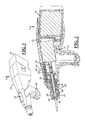
- Figure 1 is a perspective view of a surgical drill/driver according to the present invention
- Figure 2 is a perspective sectional view of the drill/driver shown in Figure 1 ;
- Figure 3 is a perspective view of various drill and driver bits utilized with the drill/driver shown in Figures 1 and 2 ;
- Figure 4 is an enlarged perspective view of an alternative arrangement collett for the drill/driver according to the present invention.
- Figure 5 is a rear perspective view of a front portion of a collett shown in Figure 4 ;
- Figure 6 is another rear perspective view of the front portion of a collett shown in Figure 4 ;
- Figure 7 is a front view of the front portion of the collett shown in Figure 4 ;
- Figure 8 is a side elevation view of the front portion of the collett shown in Figure 4 ;
- Figure 9 is a perspective view of a rear portion of the collett shown in Figure 4 ;
- Figure 10 is a side elevation view of the rear portion of the collett shown in Figure 4 ;
- Figure 11 is an enlarged perspective view of a front portion of a tubular shaft utilized with the collett of Figure 4 ;
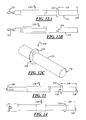
- Figure 12A is a side elevation view of a drill bit utilized with the collett shown in Figure 4 ;
- Figure 12B is a top elevation view of a drill bit utilized with the collett shown in Figure 4 ;
- Figure 12C is an enlarged perspective view of a portion of the drill bit shown in Figure 12A ;
- Figure 13 is a side elevation view of a fastener driver utilized with the collett of Figure 4 for metallic surgical screws;
- Figure 14 is a driver for lactosorbic bits utilizing the collett of Figure 4 ;
- Figure 15 is a front view of the collett shown in Figure 4 illustrating a bit being installed within the collett;
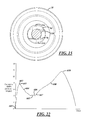
- Figure 16 is a graphic representation of a method utilizing the drill/driver according to the present invention illustrating the relationship between torque level and time;
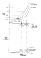
- Figure 17 is a graphic representation of the method of illustrating the relationship of torque level acceleration and time of the method represented in Figure 16 ;
- Figure 18 is a view similar to that of Figure 16 illustrating the aforementioned method of utilizing a larger surgical screw than that utilized in the generation of the relationship illustrated in Figure 3 ;
- Figure 19 is a graphic representation similar to that of Figure 17 illustrating the relationship between torque level acceleration and time of the method represented in Figure 18 ;
- Figure 20 is a view similar to that of Figure 16 which additionally shows the relationship between torque level and time for multiple densities of bone;
- Figure 21 is a graphical representation similar to that of Figure 17 illustrating the relationship between torque level acceleration and time of the methods represented in Figure 20 ;
- Figure 22 is a graphical representation of another preferred embodiment method utilizing the drill/driver according to the present invention.
- the surgical drill/driver 7 has a drill body 10.
- the drill body 10 is typically fabricated from a metal or polymeric material.
- the drill body 10 in its rearward end is connected with a battery pack 14 to allow the surgical drill/driver 7 to function without a power cord.
- the drill body 10 mounts a brushless motor 11.
- the motor 11 typically has a nominal 20 watt output with a stall torque of 195 m Nm and has a variable (no load) speed to 35,500 rpm.
- a large portion of the control electronics are located on a circuit board 23 located under the motor 11.
- the drill body 10 has a handle 22.
- An overhead manual control trigger 24 is responsive to an input of the surgeon. The trigger 24 provides a manual command signal to the motor 11.
- the motor 11 drives an outer shaft 25.
- the outer shaft drives an inner shaft 26.
- At an extreme end of the inner shaft 26 is a collet connecter 28.
- a forward push on the collet 28 positions an enlarged portion 30 of a collet multiple inner diameter 32 to be adjacent to a retainer bearing ball 34 allowing the retainer ball to be pushed outwardly of its retainer aperture 36 in the inner shaft 26.
- Selectively connected with the collet 28 is a plurality of bits 42 and 44.
- the bit 42 is for a screw driver blade.
- the bit 44 is for a drill.
- the bit 44 is for a specific set of a titanium screw. Not shown are other bits that would be for other size screws or bio-absorbable screws.
- the bit 42 functions for several sizes of titanium screws of various lengths and diameters.
- Each bit has a shank portion with a unique length that is measured from a flange 47 to the shank extreme end.
- the shank portion 43 for the bit 42 can have a length "A" of approximately 0.445 inches.
- the portion of the shank from the flange to an annular groove 45 that mates with the retaining bearing ball 34 is typically constant for all of the bits.
- Shank 54 provided for the drill bit 44 can have a length of approximately 0.563 inches. As explained later, the shank lengths are used to identify to a controller of the drill/driver 7 what bit is connected with the collet 28.
- a plunger 62 Slidably mounted within the inner shaft 26 is a plunger 62.
- the plunger 62 is spring loaded to make abutting contact with the shank of a bit connected with the collet 28.
- a set of reflector targets 66 are connected with the plunger 62.
- a positional sensor (or sensors) located on a bottom of a printed circuit board 65 underneath the trigger 24 determines an axial location of the plunger 62 by determining the position of targets 66.
- each bit has a portion with a unique length as an identifying characteristic.
- the identifying characteristic of the various bits can be electrical resistance, shank geometry or shape magnetic field strength of the shank, or radio frequency identification optical characteristics or often identifying characteristics. Desirable ranges of various operational parameter(s) specific to the identified bit are stored in a memory.
- the memory can communicate with a controller (typically located on a circuit board 23)
- predetermined desired operational parameters such as speed, torque levels, insertion rates and/or derivatives thereof, are alerted from the memory to the controller to control the operation of the drill/driver 7.
- a rotational speed sensor informs the controller of rotational speed data. Additionally other sensors may provide the controller with other operational parameter realized data.
- the controller provides an override function. If the surgeon attempts to operate the drill or driver outside of the predetermined operation parameters for a given bit, the controller provides an override function to override the manual command signal provided by the surgeon. For example, when the drill/driver 7 is in the drill mode, the drill/driver 7 can be provided with a timed automatic shut off (to prevent overheating of the motor 11).
- the turn off of the drill/driver 7 to prevent overheating is also programmed to be disabled whenever the controller determines that there is a torque level greater than 0 inch-ounces that informs the controller that the drill bit 44 is currently within bone material and therefore shutting off of the drill/driver 7 should not be allowed to prevent a drill bit 44 being stuck within a patients' bone matter.
- Collett 70 has a front piece 72 and a rear closing end piece 74.
- the front piece 72 has a generally oblong window 76.
- An interior of the front piece 72 has a generally circular bore 78 with two chordal flats 80. Extending generally radially from a portion of the chordal flats 80 are two triangular stops 82. Rearward of the circular bore 78 is a spring chamber 84.
- the collett front piece has a rearward end 86.
- the collett rearward member 74 has an annular portion 75 which is fitted within the spring chamber 84 of the forward piece 72.
- a generally tubular shaft 88 Powered by the motor 11 is a generally tubular shaft 88.
- the tubular shaft 88 has a central bore 90.
- Slidably axially mounted within the tubular bore 90 is a plunger 92.
- Connected on the front end of the tubular shaft 88 are two opposed hook stops 94.
- Each hook stop 94 has a nest 96 and an overlapping cantilever portion 98.
- the tubular shaft 88 has two chordal flats 100 which are mated with the chordal flats 80 of the collett front piece to angularly retain the collett 70 with the shaft 88.
- the shaft 88 additionally has a C-ring groove 102 for installation of a C-ring (not shown) that retains a spring (not shown) that pushes against the C-ring.
- the spring additionally pushes against a generally annular flat 77 of the collett rearward portion 74 to bias the collett 70 rearward towards a remainder of the drill/driver.
- a drill bit 110 is shown with a distal working end 112 providing a drilling portion.
- the drill bit additionally has opposite radially projecting wings 114 having flats 116.
- the bit 110 has an identifier end portion 115 of a unique length 118 from a front of the intermediate wing 114 to its proximal end 120. End 120, upon installation with the drill/driver, abuts the plunger 92 as the identifier end 115 is installed within the bore 90 of the shaft 88.
- the length 118 is identified by afore described drill/driver sensor system informing the controller that a bit 110 is connected.
- a metallic surgical screw driver bit 126 is provided having a torsional screw driver head 105.
- Bit 126 also has wings 114 with associated flats 116 and has a unique length 130 from the wings 114 to its end 128.
- lactosorbic driver bit 140 Another bit which can be utilized with the drill/driver 7 of the present invention is a lactosorbic driver bit 140.
- the lactosorbic driver bit 140 is utilized for driving a lactosorb surgical screw and again has wings 114 with a unique length 142 from the forward end of the wing 114 to bit end 144.
- the drill/driver 7 can have a time limiter that will turn off the drill/driver in exceptional cases wherein the lactosorbic screw does not shear as designed to keep the drill/driver 7 from burning up or otherwise malfunctioning.
- a more detailed review of the use of lactosorbic screws can be found by a review of Garcia et al., U.S. Patent Publication No. 2008/0215060 A1 .
- the collett 70 is pulled forward against the force of the biasing spring (not shown).
- the end of a bit for example, bit 110 with identifier end portion 115, is inserted within the collett window 76 with an angular orientation of the wings 114 such that the wings are generally aligned with the window 76.
- the bit end 120 contacts the plunger 92 and pushes the plunger back until the wings 114 contact a generally annular flat 150 of the shaft.
- the bit 110 is torqued bringing the wings 114 into their generally locked position within nest 96 of the stops 94 and are captured underneath the portion 98 of the stop.
- the spring pushes the collett 70 rearward causing the triangular stops 82 to be positioned in contact with the wings 114 on an opposite side of the wings 114 from the nest 96 of the shaft, therefore locking the wings 114 of the bit 110 in both angular directions.
- the bit 110 is now ready for use. To change the bit 110, a surgeon need only to pull forward on the collett 70 and rotate the bit 110 bringing the bit's wings 114 out from their locked position underneath the stops 94 of the shaft and aligning the wings 114 with the window 76 of the collett for release.
- Figure 16 is a graphic representation of torque level versus time.
- Figure 17 is a graphic representation of the torque level acceleration versus time of the surgical drill/driver utilized in Figure 16.
- Figure 18 displays the torque level verses time characteristics of the same type of surgical screw utilizing the same driver that is utilized in Figure 16 . However in Figure 18 the screw has an enlarged diameter and or enlarged length as compared with the screw utilized in Figure 16.
- Figure 19 is a graphic representation of the torque level acceleration versus time of the surgical drill driver utilized in Figure 18 .
- the middle line of Figure 20 is a graphic representation of torque level versus time for the same screw and same bit utilized in developing the graphic representation of Figure 16 . Additionally in Figure 20 , graphic representations are given for torque level versus time when a patient has a higher or lower bone density than normal.
- Figure 21 is a graphic representation of torque level acceleration versus time of the surgical drill/driver utilized in Figure 20 .
- the surgical drill/driver has approximately three stages of operation.
- the first stage of operation is initial thread insertion labeled 200 in Fig. 16 .
- the second stage of operation is of that when a head of the surgical screw first contacts a plate.
- the second stage of operation is labeled 202.
- the third stage of operation of the surgical drill/driver labeled 204 is that of compression of the bone of the patient wherein the plate is being pressed against the patients' bone.
- Prior to the present invention when manually torquing surgical screws to a patient by virtue of the tactile touch, the surgeon would realize when there was an increase of torque and hold up before there was strip out of the bone material. As mentioned previously, this manual method could possibly take five seconds or more of operation by the surgeon.
- the graphic representation in Figure 16 is that typically of a titanium surgical screw of 1.5mm diameter and 4mm or 5mm in length.
- An example of such a screw is a 91-6104 and 91-6105 screw manufactured by Biomet.
- section 200 represents initial thread insertion. At the end of initial thread insertion (time t 1 ), torque level is at TL1.
- FIG. 17 there is a graph of torque level acceleration versus time in seconds.
- intersection 210 and time “t 1 " there is an initial peak 213 of torque level acceleration that is sensed and signaled to the controller of the drill/driver 7.
- the acceleration of torque level goes down although the actual torque level is increasing until the screw head and plate (bottom out) against the patient's body at intersection 214 ( Figure 16 ) causing a second peaking in torque level acceleration referred to as item 215 in Figure 17 .
- Peak 215 occurs at torque level TL2 at time t 2 .
- the controller shuts off the surgical drill/driver 7 to prevent bone strip out. This causes the torque output to go to zero at time t3 along a path shown by line 220 rather than proceeding along portion 222 that would cause strip out at position 206.
- Position 206 is typically above 12-16 inch-ounces.
- the graphical representation of torque level and torque level acceleration are provided for the same drill/driver 7 utilizing the same driver bit with the exception of a larger diameter screw and/or longer length screw.
- both of these contribute to the time t 1 * (for the initial insertion stage 300) being greater than the time t 1 .
- the first spike in acceleration noted as 313 occurs at t 1 *.
- the surgical screw head makes contact with the plate.
- FIGs. 20 and 21 the torque level versus time and torque level acceleration verses time graphic charts are given for using the surgical drill/driver 7 with the same driver bit as utilized in Figures 16 and 17 as provided.
- the same size surgical screw is being utilized.
- the middle line is identical to that of Figure 16 and represents the surgical screw being applied to a patient with a bone having medium density.
- the upper line is for the surgical screw being applied to a patient with a bone mass with a higher density.
- the lower line is for the surgical screw being applied to a patient with a damaged, thinner or lower bone density and/or bone mass.
- the time t 1 ** required for thread insertion 400 is greater than that of t 1 .
- the absolute torque level TL1** is greater than that of TL1 and additionally the torque level TL2** of the drill/driver 7 shut off is higher than the torque level TL2 in the medium density bone mass.
- the time t 1 *** required for thread insertion 500 is less than that of t 1.
- the absolute torque level TL1*** is less than that of TL1 and additionally the torque level TL2*** of drill/driver shut off is lower than the torque level TL2 at shut off in the stronger medium density bone mass.
- the battery When utilizing the drill/driver 7 of the present invention, the battery is first placed inside of the drill/driver. An LED (light emitting diode) button turns on to indicate to the surgeon that power is flowing to the drill/driver 7.
- the collet 28 (or 70) is pulled forward to load a desired bit or drill into the same. If the drill/driver 7 is utilized for driving a screw, a screw is loaded to the driver from a tray (not shown). A plate (not shown) is placed against the patient's bone and the tip of the screw is contacted against the patient's bone through a hole in the plate.
- the drill/driver 7 is configured so that a pressure force must be applied against the screw by the drill/driver 7of approximately two pounds or the trigger 24 is inoperative to start the drill/driver 7. The two pounds of force are required so that the screw propels forward during the insertion state. It should be noted that in the drilling mode, a pressure force upon the patient's body by drill/driver 7 is not required.
- the control system typically located on a circuit board within the drill/driver
- the drill/ driver 7 is removed and the next screw is loaded to the drill/driver and the task is repeated.
- Figure 22 is a graphic representation of a method of utilization of the drill/driver 7 of the current invention that illustrates the relationship between torque level and time.
- the drill driver 7 As mentioned previously, is preloaded against the patient's bone matter to allow for the trigger 24 to be responsive to the surgeon's activation.
- current current level
- This torsional force peaks at position 602 as the screw starts an initial turning.
- torque begins to diminish the controller recognizes that there has been a first peak of torque level.
- the first derivative of torque level turns negative as the fastener approaches a strip out condition in the patient's bone matter wherein after the controller cuts off current to the motor 11 to prevent strip out from occurring. It is apparent to those skilled in the art that a graph similar to that as shown in Figure 22 will be slightly above the graph of Figure 22 or below the graph of Figure 22 depending upon different conditions of bone density as previously described in relationship with the graph of Figure 20 .
Landscapes
- Health & Medical Sciences (AREA)
- Surgery (AREA)
- Life Sciences & Earth Sciences (AREA)
- Engineering & Computer Science (AREA)
- Orthopedic Medicine & Surgery (AREA)
- Medical Informatics (AREA)
- Public Health (AREA)
- Nuclear Medicine, Radiotherapy & Molecular Imaging (AREA)
- Biomedical Technology (AREA)
- Heart & Thoracic Surgery (AREA)
- Veterinary Medicine (AREA)
- Molecular Biology (AREA)
- Animal Behavior & Ethology (AREA)
- General Health & Medical Sciences (AREA)
- Oral & Maxillofacial Surgery (AREA)
- Mechanical Engineering (AREA)
- Dentistry (AREA)
- Pathology (AREA)
- Neurology (AREA)
- Physics & Mathematics (AREA)
- Electromagnetism (AREA)
- Surgical Instruments (AREA)
Priority Applications (1)
| Application Number | Priority Date | Filing Date | Title |
|---|---|---|---|
| EP18163605.1A EP3473194B1 (de) | 2010-06-03 | 2011-06-03 | Chirurgische vorrichtung mit intelligenter bit-erfassung zum einstellen eines gewünschten anwendungsmodus |
Applications Claiming Priority (1)
| Application Number | Priority Date | Filing Date | Title |
|---|---|---|---|
| US39680310P | 2010-06-03 | 2010-06-03 |
Related Child Applications (1)
| Application Number | Title | Priority Date | Filing Date |
|---|---|---|---|
| EP18163605.1A Division EP3473194B1 (de) | 2010-06-03 | 2011-06-03 | Chirurgische vorrichtung mit intelligenter bit-erfassung zum einstellen eines gewünschten anwendungsmodus |
Publications (2)
| Publication Number | Publication Date |
|---|---|
| EP2392269A1 true EP2392269A1 (de) | 2011-12-07 |
| EP2392269B1 EP2392269B1 (de) | 2018-03-28 |
Family
ID=44515157
Family Applications (2)
| Application Number | Title | Priority Date | Filing Date |
|---|---|---|---|
| EP18163605.1A Active EP3473194B1 (de) | 2010-06-03 | 2011-06-03 | Chirurgische vorrichtung mit intelligenter bit-erfassung zum einstellen eines gewünschten anwendungsmodus |
| EP11168733.1A Active EP2392269B1 (de) | 2010-06-03 | 2011-06-03 | Chirurgische Vorrichtung mit intelligenter Bit-Erfassung zum Einstellen eines gewünschten Anwendungsmodus |
Family Applications Before (1)
| Application Number | Title | Priority Date | Filing Date |
|---|---|---|---|
| EP18163605.1A Active EP3473194B1 (de) | 2010-06-03 | 2011-06-03 | Chirurgische vorrichtung mit intelligenter bit-erfassung zum einstellen eines gewünschten anwendungsmodus |
Country Status (3)
| Country | Link |
|---|---|
| US (5) | US8529567B2 (de) |
| EP (2) | EP3473194B1 (de) |
| CN (1) | CN202505475U (de) |
Cited By (7)
| Publication number | Priority date | Publication date | Assignee | Title |
|---|---|---|---|---|
| CN104487007A (zh) * | 2012-05-23 | 2015-04-01 | 史赛克公司 | 包括工具单元以及对工具单元激励和控制的单独电池和控制模块的电动手术工具组件 |
| FR3020300A1 (fr) * | 2014-04-25 | 2015-10-30 | Renault Georges Ets | Dispositif de vissage a moyens de reconnaissance d'accessoire de vissage en position coaxiale |
| WO2018064647A1 (en) * | 2016-09-30 | 2018-04-05 | Kerr Corporation | Optical tool recognition system for dental devices |
| EP3413812A4 (de) * | 2016-02-12 | 2019-10-16 | Smart Medical Devices, Inc. | Antriebsvorrichtungen zur bestimmung der materialstärke in echtzeit |
| AU2019201877B2 (en) * | 2012-11-26 | 2020-11-19 | Gauthier Biomedical, Inc. | Electronic torque wrench |
| US11787025B2 (en) | 2010-05-18 | 2023-10-17 | Gauthier Biomedical, Inc. | Electronic torque wrench |
| US12318095B2 (en) | 2008-06-26 | 2025-06-03 | Quartus Engineering, Inc. | Depth controllable and measurable medical driver devices and methods of use |
Families Citing this family (44)
| Publication number | Priority date | Publication date | Assignee | Title |
|---|---|---|---|---|
| US10383629B2 (en) * | 2009-08-10 | 2019-08-20 | Covidien Lp | System and method for preventing reprocessing of a powered surgical instrument |
| WO2011123703A1 (en) * | 2010-03-31 | 2011-10-06 | Smart Medical Devices, Inc. | Depth controllable and measurable medical driver devices |
| US8529567B2 (en) | 2010-06-03 | 2013-09-10 | Biomet Microfixation, Llc | Surgical device with smart bit recognition collet assembly to set a desired application mode |
| EP3090838B1 (de) | 2011-05-19 | 2020-06-17 | Black & Decker Inc. | Elektrowerkzeug mit kraftsensorelektrokupplung |
| US9320527B2 (en) * | 2013-01-18 | 2016-04-26 | Biomet Manufacturing, Llc | Quick-connect anti-rotation peg/drill bit component |
| US9615816B2 (en) | 2013-03-15 | 2017-04-11 | Vidacare LLC | Drivers and drive systems |
| JP6755794B2 (ja) | 2013-07-19 | 2020-09-16 | プロ−デツクス・インコーポレイテツド | トルク制限ドライバ |
| US9370372B2 (en) * | 2013-09-04 | 2016-06-21 | Mcginley Engineered Solutions, Llc | Drill bit penetration measurement systems and methods |
| US9724795B2 (en) * | 2013-11-07 | 2017-08-08 | Apex Brands, Inc. | Tooling system with visual identification of attached component |
| AU2014346458B2 (en) | 2013-11-08 | 2018-11-29 | Mcginley Engineered Solutions, Llc | Surgical saw with sensing technology for determining cut through of bone and depth of the saw blade during surgery |
| USD759244S1 (en) * | 2013-11-15 | 2016-06-14 | Mcginley Engineered Solutions, Llc | Drill |
| USD759245S1 (en) * | 2013-11-15 | 2016-06-14 | Mcginley Engineered Solutions, Llc | Drill assembly |
| WO2015168359A1 (en) * | 2014-04-30 | 2015-11-05 | Gyrus Acmi, Inc., D.B.A. Olympus Surgical | Rotary tool with improved coupling assembly |
| AU2015312037A1 (en) * | 2014-09-05 | 2017-03-02 | Mcginley Engineered Solutions, Llc | Instrument leading edge measurement system and method |
| US10265082B2 (en) | 2015-08-31 | 2019-04-23 | Medtronic Ps Medical, Inc. | Surgical burs |
| US10390869B2 (en) | 2015-10-27 | 2019-08-27 | Mcginley Engineered Solutions, Llc | Techniques and instruments for placement of orthopedic implants relative to bone features |
| US10321921B2 (en) * | 2015-10-27 | 2019-06-18 | Mcginley Engineered Solutions, Llc | Unicortical path detection for a surgical depth measurement system |
| US10321920B2 (en) * | 2015-11-06 | 2019-06-18 | Mcginley Engineered Solutions, Llc | Measurement system for use with surgical burr instrument |
| WO2017083989A1 (en) * | 2015-11-16 | 2017-05-26 | Ao Technology Ag | Surgical power drill including a measuring unit suitable for bone screw length determination |
| DE102016202233A1 (de) * | 2016-02-15 | 2017-08-17 | Robert Bosch Gmbh | Transportvorrichtung zum transport von abtriebswerkzeugen am werkzeug, werkzeug und verfahren zur kommunikation zwischen einem werkzeug und einer transportvorrichtung |
| CN114404015B (zh) * | 2016-06-07 | 2024-06-21 | 普罗德克斯有限公司 | 扭矩限制装置 |
| US11076871B2 (en) | 2016-08-31 | 2021-08-03 | Medtronic Ps Medical, Inc. | Multiple connection drive shaft |
| WO2018140646A1 (en) * | 2017-01-25 | 2018-08-02 | Smith & Nephew, Inc. | Feature-based surgical tool identification |
| US11523833B2 (en) * | 2017-02-17 | 2022-12-13 | Globus Medical, Inc. | Surgical rotary tool |
| US11065069B2 (en) | 2017-05-10 | 2021-07-20 | Mako Surgical Corp. | Robotic spine surgery system and methods |
| US11033341B2 (en) | 2017-05-10 | 2021-06-15 | Mako Surgical Corp. | Robotic spine surgery system and methods |
| US10608501B2 (en) | 2017-05-24 | 2020-03-31 | Black & Decker Inc. | Variable-speed input unit having segmented pads for a power tool |
| US10483901B2 (en) | 2017-07-10 | 2019-11-19 | Newfrey Llc | System and method for installation and verification of fasteners |
| WO2019014880A1 (zh) * | 2017-07-19 | 2019-01-24 | 深圳和而泰智能控制股份有限公司 | 一种可自动识别钻头的电动装置、钻头及电动工具 |
| US11896239B2 (en) | 2017-08-17 | 2024-02-13 | Stryker Corporation | Surgical handpiece system for depth measurement and related accessories |
| EP3672501B1 (de) * | 2017-08-25 | 2023-06-14 | McGinley Engineered Solutions, LLC | Erfassung der platzierung eines chirurgischen instruments in bezug auf anatomische strukturen |
| US10806525B2 (en) | 2017-10-02 | 2020-10-20 | Mcginley Engineered Solutions, Llc | Surgical instrument with real time navigation assistance |
| US11576684B2 (en) * | 2017-11-21 | 2023-02-14 | Mcginley Engineered Solutions, Llc | Drill bit data management for penetration-monitoring drill |
| CN109805981B (zh) * | 2017-11-22 | 2024-02-27 | 苏州微创骨科医疗工具有限公司 | 医用工具 |
| US11510686B2 (en) | 2018-07-05 | 2022-11-29 | Conmed Corporation | Retrograde drilling device |
| CA3105137A1 (en) | 2018-08-20 | 2020-02-27 | Pro-Dex, Inc. | Torque-limiting devices, systems, and methods |
| JP7250594B2 (ja) * | 2019-04-01 | 2023-04-03 | 株式会社ディスコ | ドライバー |
| JP7576047B2 (ja) | 2019-05-15 | 2024-10-30 | ストライカー・コーポレイション | ビットの回転磁場を識別する電動式外科用ドリル装置 |
| KR20220058490A (ko) | 2019-06-03 | 2022-05-09 | 가우스 서지컬, 인크. | 수술 물품 추적 시스템 및 방법 |
| DE102019121121A1 (de) * | 2019-08-05 | 2021-02-11 | Aesculap Ag | Medizinische Antriebseinheit der Handheld-Bauart mit Sensoreinrichtung und Kick-Back-Control |
| US11529180B2 (en) | 2019-08-16 | 2022-12-20 | Mcginley Engineered Solutions, Llc | Reversible pin driver |
| US20220087754A1 (en) * | 2020-09-24 | 2022-03-24 | Mako Surgical Corp. | Interlocking Collet System For A Surgical Device |
| US20240260970A1 (en) * | 2023-02-03 | 2024-08-08 | Alexander M. Crespo | System, apparatus and method comprising a smart drill |
| CN116158792B (zh) * | 2023-03-02 | 2023-12-19 | 露卡(重庆)医疗设备有限公司 | 一种手柄识别刨削机 |
Citations (5)
| Publication number | Priority date | Publication date | Assignee | Title |
|---|---|---|---|---|
| US4705038A (en) * | 1985-01-23 | 1987-11-10 | Dyonics, Inc. | Surgical system for powered instruments |
| US5154242A (en) * | 1990-08-28 | 1992-10-13 | Matsushita Electric Works, Ltd. | Power tools with multi-stage tightening torque control |
| US5591919A (en) * | 1993-04-20 | 1997-01-07 | Ingersoll-Rand Company | Method and apparatus for monitoring and controlling tightening of prevailing torque fasteners |
| US20050131415A1 (en) * | 2002-04-24 | 2005-06-16 | Hearn Trevor C. | Adaptive apparatus for driving a threaded device into material such as a biological tissue |
| US20080215060A1 (en) | 2007-03-02 | 2008-09-04 | Garcia Saddy R | Fastener insertion method |
Family Cites Families (60)
| Publication number | Priority date | Publication date | Assignee | Title |
|---|---|---|---|---|
| US2414882A (en) * | 1943-09-24 | 1947-01-28 | Herschel Leiter H | Fracture reduction apparatus |
| US3962910A (en) | 1973-08-20 | 1976-06-15 | Ingersoll-Rand Company | Method and apparatus for fastener tension inspection |
| US3926264A (en) | 1973-11-23 | 1975-12-16 | Thor Power Tool Co | Control circuit for a power tool |
| US4095325A (en) | 1974-12-24 | 1978-06-20 | Sanyo Machine Works, Ltd. | Method for tightening bolts |
| USRE31569E (en) | 1976-08-09 | 1984-05-01 | Rockwell International Corporation | Tension control of fasteners |
| US4244213A (en) | 1979-03-15 | 1981-01-13 | Gse, Inc. | Retorque measuring apparatus |
| US4267914A (en) | 1979-04-26 | 1981-05-19 | Black & Decker Inc. | Anti-kickback power tool control |
| US4249117A (en) | 1979-05-01 | 1981-02-03 | Black And Decker, Inc. | Anti-kickback power tool control |
| US4273198A (en) | 1979-07-09 | 1981-06-16 | Daiichi Dentsu Kabushiki Kaisha | Motor-driven clamping method and device |
| US4450727A (en) | 1982-04-29 | 1984-05-29 | Gse, Inc. | Digital retorque measuring apparatus |
| US4684922A (en) | 1986-01-15 | 1987-08-04 | Analog Devices, Inc. | Temporal averaging using a voltage mode D/A converter |
| US4721169A (en) * | 1986-05-14 | 1988-01-26 | Matsushita Electric Industrial Co., Ltd. | Electric driver with torque-adjustable clutch mechanism |
| US5217478A (en) * | 1987-02-18 | 1993-06-08 | Linvatec Corporation | Arthroscopic surgical instrument drive system |
| JPH01171777A (ja) | 1987-12-23 | 1989-07-06 | Honda Motor Co Ltd | ナツトランナーの制御方法及び装置 |
| DE3805179A1 (de) * | 1988-02-19 | 1989-08-31 | Wolf Gmbh Richard | Geraet mit einem rotierend angetriebenen chirurgischen instrument |
| US4894767A (en) | 1988-03-31 | 1990-01-16 | Daiichi Dentsu Kabushiki Kaisha | Method for yield tightening of screws |
| US5014793A (en) | 1989-04-10 | 1991-05-14 | Measurement Specialties, Inc. | Variable speed DC motor controller apparatus particularly adapted for control of portable-power tools |
| US5155421A (en) | 1989-06-12 | 1992-10-13 | Atlas Copco Tools Ab | Power wrench for tightening screw joints |
| JPH0379279A (ja) | 1989-08-15 | 1991-04-04 | Hayashi Tokei Kogyo Kk | 電動ドライバ |
| US5038084A (en) | 1990-08-15 | 1991-08-06 | Wing Thomas W | Drill motor control |
| US5152046A (en) * | 1990-10-24 | 1992-10-06 | Sanyo Kiko Kabushiki Kaisha | Fastener tightening method |
| US5207697A (en) * | 1991-06-27 | 1993-05-04 | Stryker Corporation | Battery powered surgical handpiece |
| US5315501A (en) | 1992-04-03 | 1994-05-24 | The Stanley Works | Power tool compensator for torque overshoot |
| WO1993025151A1 (en) * | 1992-06-12 | 1993-12-23 | Larry Steven Nichter | Wire driver and method |
| US5410229A (en) | 1992-07-31 | 1995-04-25 | Black & Decker Inc. | Motor speed control circuit with electronic clutch |
| JP3411921B2 (ja) * | 1993-02-19 | 2003-06-03 | ボストン サイエンティフィック コーポレイション | 外科用摘出器 |
| US5396703A (en) * | 1993-04-20 | 1995-03-14 | Ingersoll-Rand Company | Method of inspecting bearing insert assemblies |
| GB9320181D0 (en) | 1993-09-30 | 1993-11-17 | Black & Decker Inc | Improvements in and relating to power tools |
| US5637968A (en) * | 1993-10-25 | 1997-06-10 | The Stanley Works | Power tool with automatic downshift feature |
| US5601560A (en) * | 1994-10-07 | 1997-02-11 | The Anspach Effort, Inc. | Tool bit for a motor driven surgical instrument |
| US6479958B1 (en) | 1995-01-06 | 2002-11-12 | Black & Decker Inc. | Anti-kickback and breakthrough torque control for power tool |
| DE19620782A1 (de) | 1995-06-03 | 1996-12-05 | Volkswagen Ag | Verfahren zur Herstellung einer Schraubverbindung und Vorrichtung hierfür |
| US5626474A (en) * | 1995-06-28 | 1997-05-06 | Kukla; Thomas S. | Implant torque wrench |
| US5885258A (en) * | 1996-02-23 | 1999-03-23 | Memory Medical Systems, Inc. | Medical instrument with slotted memory metal tube |
| ATE260072T1 (de) * | 1996-07-18 | 2004-03-15 | Implant Innovations Inc | Motorisch angetriebene osteotomiewerkzeuge zum verdichten von knochengewebe |
| US6017354A (en) | 1996-08-15 | 2000-01-25 | Stryker Corporation | Integrated system for powered surgical tools |
| US5993454A (en) * | 1998-09-29 | 1999-11-30 | Stryker Corporation | Drill attachment for a surgical drill |
| US6402757B1 (en) * | 1999-03-12 | 2002-06-11 | Biomet, Inc. | Cannulated fastener system for repair of bone fracture |
| US6132435A (en) * | 1999-09-14 | 2000-10-17 | Synthes (Usa) | Torque limiting device for surgical use |
| JP2001205575A (ja) | 2000-01-28 | 2001-07-31 | Nitto Kohki Co Ltd | トルク制御式インパクトレンチ |
| JP3456949B2 (ja) | 2000-06-19 | 2003-10-14 | 株式会社エスティック | ネジ締め装置の制御方法および装置 |
| AU2001284857B2 (en) * | 2000-08-11 | 2005-09-29 | Warsaw Orthopedic, Inc. | Surgical instrumentation and method for treatment of the spine |
| DE10041632A1 (de) | 2000-08-24 | 2002-03-07 | Hilti Ag | Elektrohandwerkzeuggerät mit Sicherheitskupplung |
| JP4292725B2 (ja) | 2001-03-22 | 2009-07-08 | パナソニック電工株式会社 | 締付工具 |
| US6516896B1 (en) | 2001-07-30 | 2003-02-11 | The Stanley Works | Torque-applying tool and control therefor |
| JP2003200363A (ja) | 2001-12-26 | 2003-07-15 | Makita Corp | バッテリ式電動工具 |
| US7091683B1 (en) * | 2003-10-24 | 2006-08-15 | Intelligent Automation Design, Llc | Method of monitoring and controlling the seating of screws to the optimum point of grip independent of screw size and material density |
| US7507231B2 (en) * | 2003-12-23 | 2009-03-24 | Arthrex, Inc. | Surgical power console with locking speed control |
| US6971454B2 (en) * | 2004-03-16 | 2005-12-06 | Bogue Edward M | Pulsed rotation screw removal and insertion device |
| US20060111724A1 (en) * | 2004-11-24 | 2006-05-25 | Yeung Research | Bone harvesting drill bit for oral surgery |
| US7185562B2 (en) * | 2004-12-08 | 2007-03-06 | Osteomed L.P. | Disposable battery powered screw driver, locking mechanism, and accessories |
| US7878981B2 (en) * | 2005-03-01 | 2011-02-01 | Checkpoint Surgical, Llc | Systems and methods for intra-operative stimulation |
| US20070068329A1 (en) * | 2005-07-11 | 2007-03-29 | Phan Christopher U | Curette system |
| FR2891132B1 (fr) * | 2005-09-29 | 2007-11-30 | Fkg Dentaire Sa | Procede et dispositif d'identification et de controle d'un instrument medical |
| US7578357B2 (en) * | 2006-09-12 | 2009-08-25 | Black & Decker Inc. | Driver with external torque value indicator integrated with spindle lock and related method |
| JP2009083026A (ja) * | 2007-09-28 | 2009-04-23 | Mazda Motor Corp | ボルト締結方法及びその装置 |
| JP5464434B2 (ja) * | 2010-03-31 | 2014-04-09 | 日立工機株式会社 | 電動工具 |
| US8485075B1 (en) * | 2010-05-18 | 2013-07-16 | Gauthier Biomedical, Inc. | Electronic torque wrench |
| US8529567B2 (en) | 2010-06-03 | 2013-09-10 | Biomet Microfixation, Llc | Surgical device with smart bit recognition collet assembly to set a desired application mode |
| JP5582397B2 (ja) * | 2010-08-31 | 2014-09-03 | 日立工機株式会社 | 電動工具及び電動工具に用いられる電池パック |
-
2011
- 2011-06-02 US US13/134,253 patent/US8529567B2/en not_active Expired - Fee Related
- 2011-06-03 EP EP18163605.1A patent/EP3473194B1/de active Active
- 2011-06-03 CN CN2011201946099U patent/CN202505475U/zh not_active Expired - Lifetime
- 2011-06-03 EP EP11168733.1A patent/EP2392269B1/de active Active
-
2013
- 2013-08-13 US US13/965,692 patent/US20130331895A1/en not_active Abandoned
-
2015
- 2015-09-04 US US14/846,224 patent/US9585677B2/en active Active
-
2017
- 2017-03-06 US US15/450,256 patent/US9962169B2/en active Active
-
2018
- 2018-04-05 US US15/946,352 patent/US10792050B2/en active Active
Patent Citations (5)
| Publication number | Priority date | Publication date | Assignee | Title |
|---|---|---|---|---|
| US4705038A (en) * | 1985-01-23 | 1987-11-10 | Dyonics, Inc. | Surgical system for powered instruments |
| US5154242A (en) * | 1990-08-28 | 1992-10-13 | Matsushita Electric Works, Ltd. | Power tools with multi-stage tightening torque control |
| US5591919A (en) * | 1993-04-20 | 1997-01-07 | Ingersoll-Rand Company | Method and apparatus for monitoring and controlling tightening of prevailing torque fasteners |
| US20050131415A1 (en) * | 2002-04-24 | 2005-06-16 | Hearn Trevor C. | Adaptive apparatus for driving a threaded device into material such as a biological tissue |
| US20080215060A1 (en) | 2007-03-02 | 2008-09-04 | Garcia Saddy R | Fastener insertion method |
Cited By (14)
| Publication number | Priority date | Publication date | Assignee | Title |
|---|---|---|---|---|
| US12383282B2 (en) | 2008-06-26 | 2025-08-12 | Quartus Engineering, Inc. | Depth controllable and measurable medical driver devices and methods of use |
| US12318095B2 (en) | 2008-06-26 | 2025-06-03 | Quartus Engineering, Inc. | Depth controllable and measurable medical driver devices and methods of use |
| US11787025B2 (en) | 2010-05-18 | 2023-10-17 | Gauthier Biomedical, Inc. | Electronic torque wrench |
| US12029439B2 (en) | 2012-05-23 | 2024-07-09 | Stryker Corporation | Surgical tool system with interchangeable battery and control modules |
| US10076340B2 (en) | 2012-05-23 | 2018-09-18 | Stryker Corporation | Surgical tool system with a tool unit that includes a power generating unit and a battery and control module that is releasably attached to the tool unit for energizing and controlling the power generating unit |
| CN104487007A (zh) * | 2012-05-23 | 2015-04-01 | 史赛克公司 | 包括工具单元以及对工具单元激励和控制的单独电池和控制模块的电动手术工具组件 |
| US11103254B2 (en) | 2012-05-23 | 2021-08-31 | Stryker Corporation | Surgical tool system with a battery and control module having a driver capable of reusing contacts |
| AU2019201877B2 (en) * | 2012-11-26 | 2020-11-19 | Gauthier Biomedical, Inc. | Electronic torque wrench |
| FR3020300A1 (fr) * | 2014-04-25 | 2015-10-30 | Renault Georges Ets | Dispositif de vissage a moyens de reconnaissance d'accessoire de vissage en position coaxiale |
| EP2944425A1 (de) * | 2014-04-25 | 2015-11-18 | Etablissements Georges Renault | Schraubvorrichtung mit zubehörerkennung |
| US10736643B2 (en) | 2016-02-12 | 2020-08-11 | Smart Medical Devices, Inc. | Driving devices and methods for determining material strength in real-time |
| US11839385B2 (en) | 2016-02-12 | 2023-12-12 | Quartus Engineering, Inc. | Driving devices and methods for determining material strength in real-time |
| EP3413812A4 (de) * | 2016-02-12 | 2019-10-16 | Smart Medical Devices, Inc. | Antriebsvorrichtungen zur bestimmung der materialstärke in echtzeit |
| WO2018064647A1 (en) * | 2016-09-30 | 2018-04-05 | Kerr Corporation | Optical tool recognition system for dental devices |
Also Published As
| Publication number | Publication date |
|---|---|
| US20180221032A1 (en) | 2018-08-09 |
| US20160030058A1 (en) | 2016-02-04 |
| CN202505475U (zh) | 2012-10-31 |
| US20110301611A1 (en) | 2011-12-08 |
| US20170238941A1 (en) | 2017-08-24 |
| EP3473194A2 (de) | 2019-04-24 |
| US9585677B2 (en) | 2017-03-07 |
| US10792050B2 (en) | 2020-10-06 |
| US9962169B2 (en) | 2018-05-08 |
| US20130331895A1 (en) | 2013-12-12 |
| EP3473194B1 (de) | 2020-09-16 |
| EP3473194A3 (de) | 2019-08-14 |
| EP2392269B1 (de) | 2018-03-28 |
| US8529567B2 (en) | 2013-09-10 |
Similar Documents
| Publication | Publication Date | Title |
|---|---|---|
| EP3473194B1 (de) | Chirurgische vorrichtung mit intelligenter bit-erfassung zum einstellen eines gewünschten anwendungsmodus | |
| US12156657B2 (en) | Surgical drill with telescoping member | |
| US11975427B2 (en) | Method for controlling an electric motor of a power tool | |
| EP0785751B1 (de) | Nähfadenankeranordnung | |
| CN108698219B (zh) | 电子滑动离合器的应用优化的切断性能 | |
| US6398785B2 (en) | Apparatus for rigidly fixing craniomaxillofacial tissue grafts and bone plates | |
| US5868789A (en) | Removable suture anchor apparatus | |
| JP4602984B2 (ja) | 自己穿設式アンカー | |
| US11786226B2 (en) | Single insertion multiple sample biopsy apparatus | |
| WO2008109004A1 (en) | Fastener insertion method | |
| EP0766531A1 (de) | Nähfadenankeranordung | |
| AU2003202403A1 (en) | Screw comprising an integrated screwdriver | |
| EP1764056B1 (de) | Vorrichtung zum Entfernen von Befestigungsmitteln aus menschlichem Geweben | |
| CN117693636A (zh) | 具有可变形的扩展部分的墙壁锚定件 | |
| US20090084229A1 (en) | Programmable threaded insert installation tool and method of use | |
| CN217976925U (zh) | 用于固定锚固件的工具 | |
| WO2023168327A2 (en) | Torque driver adapter |
Legal Events
| Date | Code | Title | Description |
|---|---|---|---|
| AK | Designated contracting states |
Kind code of ref document: A1 Designated state(s): AL AT BE BG CH CY CZ DE DK EE ES FI FR GB GR HR HU IE IS IT LI LT LU LV MC MK MT NL NO PL PT RO RS SE SI SK SM TR |
|
| AX | Request for extension of the european patent |
Extension state: BA ME |
|
| PUAI | Public reference made under article 153(3) epc to a published international application that has entered the european phase |
Free format text: ORIGINAL CODE: 0009012 |
|
| 17P | Request for examination filed |
Effective date: 20120607 |
|
| RAP1 | Party data changed (applicant data changed or rights of an application transferred) |
Owner name: BIOMET MICROFIXATION, LLC |
|
| RIN1 | Information on inventor provided before grant (corrected) |
Inventor name: MILLER, LARRY Inventor name: WINTERROTH, BRADLEY Inventor name: GRAY, BENJAMIN J Inventor name: GRACIA, SADDY, R. Inventor name: DYER, CHRISTOPER C. Inventor name: LUBY, RYAN NICHOLAS Inventor name: MEREDITH, ALLAN J |
|
| 17Q | First examination report despatched |
Effective date: 20151026 |
|
| GRAP | Despatch of communication of intention to grant a patent |
Free format text: ORIGINAL CODE: EPIDOSNIGR1 |
|
| INTG | Intention to grant announced |
Effective date: 20171013 |
|
| GRAS | Grant fee paid |
Free format text: ORIGINAL CODE: EPIDOSNIGR3 |
|
| GRAA | (expected) grant |
Free format text: ORIGINAL CODE: 0009210 |
|
| AK | Designated contracting states |
Kind code of ref document: B1 Designated state(s): AL AT BE BG CH CY CZ DE DK EE ES FI FR GB GR HR HU IE IS IT LI LT LU LV MC MK MT NL NO PL PT RO RS SE SI SK SM TR |
|
| REG | Reference to a national code |
Ref country code: GB Ref legal event code: FG4D |
|
| REG | Reference to a national code |
Ref country code: CH Ref legal event code: EP |
|
| REG | Reference to a national code |
Ref country code: FR Ref legal event code: PLFP Year of fee payment: 8 |
|
| REG | Reference to a national code |
Ref country code: CH Ref legal event code: NV Representative=s name: MICHELI AND CIE SA, CH |
|
| REG | Reference to a national code |
Ref country code: AT Ref legal event code: REF Ref document number: 982671 Country of ref document: AT Kind code of ref document: T Effective date: 20180415 |
|
| REG | Reference to a national code |
Ref country code: IE Ref legal event code: FG4D |
|
| REG | Reference to a national code |
Ref country code: DE Ref legal event code: R096 Ref document number: 602011046872 Country of ref document: DE |
|
| PG25 | Lapsed in a contracting state [announced via postgrant information from national office to epo] |
Ref country code: HR Free format text: LAPSE BECAUSE OF FAILURE TO SUBMIT A TRANSLATION OF THE DESCRIPTION OR TO PAY THE FEE WITHIN THE PRESCRIBED TIME-LIMIT Effective date: 20180328 Ref country code: FI Free format text: LAPSE BECAUSE OF FAILURE TO SUBMIT A TRANSLATION OF THE DESCRIPTION OR TO PAY THE FEE WITHIN THE PRESCRIBED TIME-LIMIT Effective date: 20180328 Ref country code: NO Free format text: LAPSE BECAUSE OF FAILURE TO SUBMIT A TRANSLATION OF THE DESCRIPTION OR TO PAY THE FEE WITHIN THE PRESCRIBED TIME-LIMIT Effective date: 20180628 Ref country code: LT Free format text: LAPSE BECAUSE OF FAILURE TO SUBMIT A TRANSLATION OF THE DESCRIPTION OR TO PAY THE FEE WITHIN THE PRESCRIBED TIME-LIMIT Effective date: 20180328 |
|
| REG | Reference to a national code |
Ref country code: NL Ref legal event code: MP Effective date: 20180328 |
|
| REG | Reference to a national code |
Ref country code: LT Ref legal event code: MG4D |
|
| PG25 | Lapsed in a contracting state [announced via postgrant information from national office to epo] |
Ref country code: RS Free format text: LAPSE BECAUSE OF FAILURE TO SUBMIT A TRANSLATION OF THE DESCRIPTION OR TO PAY THE FEE WITHIN THE PRESCRIBED TIME-LIMIT Effective date: 20180328 Ref country code: SE Free format text: LAPSE BECAUSE OF FAILURE TO SUBMIT A TRANSLATION OF THE DESCRIPTION OR TO PAY THE FEE WITHIN THE PRESCRIBED TIME-LIMIT Effective date: 20180328 Ref country code: LV Free format text: LAPSE BECAUSE OF FAILURE TO SUBMIT A TRANSLATION OF THE DESCRIPTION OR TO PAY THE FEE WITHIN THE PRESCRIBED TIME-LIMIT Effective date: 20180328 Ref country code: BG Free format text: LAPSE BECAUSE OF FAILURE TO SUBMIT A TRANSLATION OF THE DESCRIPTION OR TO PAY THE FEE WITHIN THE PRESCRIBED TIME-LIMIT Effective date: 20180628 Ref country code: GR Free format text: LAPSE BECAUSE OF FAILURE TO SUBMIT A TRANSLATION OF THE DESCRIPTION OR TO PAY THE FEE WITHIN THE PRESCRIBED TIME-LIMIT Effective date: 20180629 |
|
| PG25 | Lapsed in a contracting state [announced via postgrant information from national office to epo] |
Ref country code: AL Free format text: LAPSE BECAUSE OF FAILURE TO SUBMIT A TRANSLATION OF THE DESCRIPTION OR TO PAY THE FEE WITHIN THE PRESCRIBED TIME-LIMIT Effective date: 20180328 Ref country code: RO Free format text: LAPSE BECAUSE OF FAILURE TO SUBMIT A TRANSLATION OF THE DESCRIPTION OR TO PAY THE FEE WITHIN THE PRESCRIBED TIME-LIMIT Effective date: 20180328 Ref country code: PL Free format text: LAPSE BECAUSE OF FAILURE TO SUBMIT A TRANSLATION OF THE DESCRIPTION OR TO PAY THE FEE WITHIN THE PRESCRIBED TIME-LIMIT Effective date: 20180328 Ref country code: EE Free format text: LAPSE BECAUSE OF FAILURE TO SUBMIT A TRANSLATION OF THE DESCRIPTION OR TO PAY THE FEE WITHIN THE PRESCRIBED TIME-LIMIT Effective date: 20180328 Ref country code: NL Free format text: LAPSE BECAUSE OF FAILURE TO SUBMIT A TRANSLATION OF THE DESCRIPTION OR TO PAY THE FEE WITHIN THE PRESCRIBED TIME-LIMIT Effective date: 20180328 Ref country code: ES Free format text: LAPSE BECAUSE OF FAILURE TO SUBMIT A TRANSLATION OF THE DESCRIPTION OR TO PAY THE FEE WITHIN THE PRESCRIBED TIME-LIMIT Effective date: 20180328 |
|
| PG25 | Lapsed in a contracting state [announced via postgrant information from national office to epo] |
Ref country code: SM Free format text: LAPSE BECAUSE OF FAILURE TO SUBMIT A TRANSLATION OF THE DESCRIPTION OR TO PAY THE FEE WITHIN THE PRESCRIBED TIME-LIMIT Effective date: 20180328 Ref country code: SK Free format text: LAPSE BECAUSE OF FAILURE TO SUBMIT A TRANSLATION OF THE DESCRIPTION OR TO PAY THE FEE WITHIN THE PRESCRIBED TIME-LIMIT Effective date: 20180328 Ref country code: CZ Free format text: LAPSE BECAUSE OF FAILURE TO SUBMIT A TRANSLATION OF THE DESCRIPTION OR TO PAY THE FEE WITHIN THE PRESCRIBED TIME-LIMIT Effective date: 20180328 |
|
| REG | Reference to a national code |
Ref country code: AT Ref legal event code: MK05 Ref document number: 982671 Country of ref document: AT Kind code of ref document: T Effective date: 20180328 |
|
| PG25 | Lapsed in a contracting state [announced via postgrant information from national office to epo] |
Ref country code: PT Free format text: LAPSE BECAUSE OF FAILURE TO SUBMIT A TRANSLATION OF THE DESCRIPTION OR TO PAY THE FEE WITHIN THE PRESCRIBED TIME-LIMIT Effective date: 20180730 |
|
| REG | Reference to a national code |
Ref country code: DE Ref legal event code: R097 Ref document number: 602011046872 Country of ref document: DE |
|
| PG25 | Lapsed in a contracting state [announced via postgrant information from national office to epo] |
Ref country code: AT Free format text: LAPSE BECAUSE OF FAILURE TO SUBMIT A TRANSLATION OF THE DESCRIPTION OR TO PAY THE FEE WITHIN THE PRESCRIBED TIME-LIMIT Effective date: 20180328 Ref country code: DK Free format text: LAPSE BECAUSE OF FAILURE TO SUBMIT A TRANSLATION OF THE DESCRIPTION OR TO PAY THE FEE WITHIN THE PRESCRIBED TIME-LIMIT Effective date: 20180328 |
|
| PLBE | No opposition filed within time limit |
Free format text: ORIGINAL CODE: 0009261 |
|
| STAA | Information on the status of an ep patent application or granted ep patent |
Free format text: STATUS: NO OPPOSITION FILED WITHIN TIME LIMIT |
|
| 26N | No opposition filed |
Effective date: 20190103 |
|
| REG | Reference to a national code |
Ref country code: BE Ref legal event code: MM Effective date: 20180630 |
|
| PG25 | Lapsed in a contracting state [announced via postgrant information from national office to epo] |
Ref country code: MC Free format text: LAPSE BECAUSE OF FAILURE TO SUBMIT A TRANSLATION OF THE DESCRIPTION OR TO PAY THE FEE WITHIN THE PRESCRIBED TIME-LIMIT Effective date: 20180328 Ref country code: LU Free format text: LAPSE BECAUSE OF NON-PAYMENT OF DUE FEES Effective date: 20180603 |
|
| PG25 | Lapsed in a contracting state [announced via postgrant information from national office to epo] |
Ref country code: BE Free format text: LAPSE BECAUSE OF NON-PAYMENT OF DUE FEES Effective date: 20180630 Ref country code: SI Free format text: LAPSE BECAUSE OF FAILURE TO SUBMIT A TRANSLATION OF THE DESCRIPTION OR TO PAY THE FEE WITHIN THE PRESCRIBED TIME-LIMIT Effective date: 20180328 |
|
| PG25 | Lapsed in a contracting state [announced via postgrant information from national office to epo] |
Ref country code: MT Free format text: LAPSE BECAUSE OF NON-PAYMENT OF DUE FEES Effective date: 20180603 |
|
| PG25 | Lapsed in a contracting state [announced via postgrant information from national office to epo] |
Ref country code: TR Free format text: LAPSE BECAUSE OF FAILURE TO SUBMIT A TRANSLATION OF THE DESCRIPTION OR TO PAY THE FEE WITHIN THE PRESCRIBED TIME-LIMIT Effective date: 20180328 |
|
| PG25 | Lapsed in a contracting state [announced via postgrant information from national office to epo] |
Ref country code: HU Free format text: LAPSE BECAUSE OF FAILURE TO SUBMIT A TRANSLATION OF THE DESCRIPTION OR TO PAY THE FEE WITHIN THE PRESCRIBED TIME-LIMIT; INVALID AB INITIO Effective date: 20110603 |
|
| PG25 | Lapsed in a contracting state [announced via postgrant information from national office to epo] |
Ref country code: MK Free format text: LAPSE BECAUSE OF NON-PAYMENT OF DUE FEES Effective date: 20180328 Ref country code: CY Free format text: LAPSE BECAUSE OF FAILURE TO SUBMIT A TRANSLATION OF THE DESCRIPTION OR TO PAY THE FEE WITHIN THE PRESCRIBED TIME-LIMIT Effective date: 20180328 |
|
| PG25 | Lapsed in a contracting state [announced via postgrant information from national office to epo] |
Ref country code: IS Free format text: LAPSE BECAUSE OF FAILURE TO SUBMIT A TRANSLATION OF THE DESCRIPTION OR TO PAY THE FEE WITHIN THE PRESCRIBED TIME-LIMIT Effective date: 20180728 |
|
| REG | Reference to a national code |
Ref country code: DE Ref legal event code: R082 Ref document number: 602011046872 Country of ref document: DE Representative=s name: VENNER SHIPLEY GERMANY LLP, DE Ref country code: DE Ref legal event code: R082 Ref document number: 602011046872 Country of ref document: DE Representative=s name: VENNER SHIPLEY LLP, DE |
|
| PGFP | Annual fee paid to national office [announced via postgrant information from national office to epo] |
Ref country code: IE Payment date: 20220512 Year of fee payment: 12 |
|
| PGFP | Annual fee paid to national office [announced via postgrant information from national office to epo] |
Ref country code: CH Payment date: 20220702 Year of fee payment: 12 |
|
| P01 | Opt-out of the competence of the unified patent court (upc) registered |
Effective date: 20230527 |
|
| REG | Reference to a national code |
Ref country code: CH Ref legal event code: PL |
|
| REG | Reference to a national code |
Ref country code: IE Ref legal event code: MM4A |
|
| PG25 | Lapsed in a contracting state [announced via postgrant information from national office to epo] |
Ref country code: IE Free format text: LAPSE BECAUSE OF NON-PAYMENT OF DUE FEES Effective date: 20230603 |
|
| PG25 | Lapsed in a contracting state [announced via postgrant information from national office to epo] |
Ref country code: IE Free format text: LAPSE BECAUSE OF NON-PAYMENT OF DUE FEES Effective date: 20230603 Ref country code: CH Free format text: LAPSE BECAUSE OF NON-PAYMENT OF DUE FEES Effective date: 20230630 |
|
| PGFP | Annual fee paid to national office [announced via postgrant information from national office to epo] |
Ref country code: DE Payment date: 20250512 Year of fee payment: 15 |
|
| PGFP | Annual fee paid to national office [announced via postgrant information from national office to epo] |
Ref country code: GB Payment date: 20250513 Year of fee payment: 15 |
|
| PGFP | Annual fee paid to national office [announced via postgrant information from national office to epo] |
Ref country code: IT Payment date: 20250410 Year of fee payment: 15 |
|
| PGFP | Annual fee paid to national office [announced via postgrant information from national office to epo] |
Ref country code: FR Payment date: 20250509 Year of fee payment: 15 |