EP2392015B1 - Elektromagnet zur erzeugung eines substantiell gleichförmigen magnetfeldes - Google Patents
Elektromagnet zur erzeugung eines substantiell gleichförmigen magnetfeldes Download PDFInfo
- Publication number
- EP2392015B1 EP2392015B1 EP10736573.6A EP10736573A EP2392015B1 EP 2392015 B1 EP2392015 B1 EP 2392015B1 EP 10736573 A EP10736573 A EP 10736573A EP 2392015 B1 EP2392015 B1 EP 2392015B1
- Authority
- EP
- European Patent Office
- Prior art keywords
- central axis
- magnetic solenoid
- magnetic
- radius
- along
- Prior art date
- Legal status (The legal status is an assumption and is not a legal conclusion. Google has not performed a legal analysis and makes no representation as to the accuracy of the status listed.)
- Active
Links
Images


Classifications
-
- H—ELECTRICITY
- H01—ELECTRIC ELEMENTS
- H01F—MAGNETS; INDUCTANCES; TRANSFORMERS; SELECTION OF MATERIALS FOR THEIR MAGNETIC PROPERTIES
- H01F7/00—Magnets
- H01F7/06—Electromagnets; Actuators including electromagnets
- H01F7/20—Electromagnets; Actuators including electromagnets without armatures
- H01F7/202—Electromagnets for high magnetic field strength
-
- G—PHYSICS
- G01—MEASURING; TESTING
- G01C—MEASURING DISTANCES, LEVELS OR BEARINGS; SURVEYING; NAVIGATION; GYROSCOPIC INSTRUMENTS; PHOTOGRAMMETRY OR VIDEOGRAMMETRY
- G01C19/00—Gyroscopes; Turn-sensitive devices using vibrating masses; Turn-sensitive devices without moving masses; Measuring angular rate using gyroscopic effects
- G01C19/58—Turn-sensitive devices without moving masses
- G01C19/60—Electronic or nuclear magnetic resonance gyrometers
-
- G—PHYSICS
- G01—MEASURING; TESTING
- G01R—MEASURING ELECTRIC VARIABLES; MEASURING MAGNETIC VARIABLES
- G01R33/00—Arrangements or instruments for measuring magnetic variables
- G01R33/20—Arrangements or instruments for measuring magnetic variables involving magnetic resonance
- G01R33/28—Details of apparatus provided for in groups G01R33/44 - G01R33/64
- G01R33/38—Systems for generation, homogenisation or stabilisation of the main or gradient magnetic field
- G01R33/381—Systems for generation, homogenisation or stabilisation of the main or gradient magnetic field using electromagnets
Definitions
- the present invention relates generally to magnetic device systems, and specifically to a magnetic solenoid for generating a substantially uniform magnetic field.
- Magnetic solenoids can be implemented for a variety of applications to generate a magnetic field, such as in an inner volume of the magnetic solenoid.
- magnetic solenoids can be implemented to generate a magnetic field for a gyroscope, such as a nuclear magnetic resonance (NMR) gyroscope that is located within the inner volume of the magnetic solenoid, to induce precession of noble gas isotopes.
- NMR nuclear magnetic resonance
- magnetic solenoids can be formed of a conductive coil that is configured with a cylindrical geometry.
- a cylindrical configuration of the conductive coil can result in an unacceptable non-uniformity of the magnetic field, such as near the ends of the cylindrical configuration and at points that are off-axis from a central axis of the cylindrical configuration.
- JP S61 82404 discloses a superconducting magnet for generating a uniform magnetic field made of a superconducting wire wherein the outer diameter gradually increases.
- GB 2 306 007 discloses a MRI magnet with flared openings.
- One embodiment of the invention includes a magnetic solenoid according to claim 1.
- the present invention relates generally to magnetic device systems, and specifically to a magnetic solenoid for generating a substantially uniform magnetic field.
- the magnetic solenoid can include a conductive coil that has a radius about a central axis that is defined by a compound equation at each point along the central axis.
- the compound equation can have a first operand that can be an elliptical or circular function having a minor axis that defines the radius of the conductive coil at a midpoint of the magnetic solenoid along the central axis.
- the first operand can define a rounded center portion of the magnetic solenoid having a variable radius of the conductive coil along the length, with the radius having a maximum value at the midpoint of the magnetic solenoid along the central axis.
- the first operand can thus be effective to provide along-axis uniformity of the magnetic field within the inner volume of the magnetic solenoid.
- the compound equation can also have a second operand that can be, for example, one of an exponential, parabolic, or hyperbolic function.
- the second operand can define a flaring of the radius of the conductive coil away from the central axis at each end of the magnetic solenoid.
- the second operand can thus be effective to provide off-axis uniformity of the magnetic field within the inner volume of the magnetic solenoid.
- the magnetic solenoid can thus be substantially symmetrical about a plane at the midpoint of the magnetic solenoid along the central axis.
- the compound equation can have three operands.
- the first operand can define a radius at the midpoint of the magnetic solenoid along the central axis.
- the second and third operands can each be exponential functions.
- the second and third operands can each include pre-selected constants and can have magnitudes that vary as a function of distance from the midpoint of the magnetic solenoid along the central axis.
- the second operand can be subtracted from the first operand and the third operand can be added to the first operand.
- the second and third operands can be selected to vary the radius along the central axis to define a rounded center portion of the magnetic solenoid having a variable radius of the conductive coil along the length and to define a flaring of the radius of the conductive coil away from the central axis at each end of the magnetic solenoid.
- FIG. 1 illustrates an example of a perspective view of a magnetic solenoid 10 in accordance with an aspect of the invention.
- the magnetic solenoid 10 can be implemented in any of a variety of applications that utilize a magnetic field, such as in a nuclear magnetic resonance (NMR) gyroscope application.
- NMR nuclear magnetic resonance
- the magnetic solenoid 10 is demonstrated in a side view 12 and in an isometric view 14.
- the magnetic solenoid 10 includes a coil form 16, around which is wound a conductive coil (not shown) that is configured to generate a substantially uniform magnetic field within an inner volume 18 of the magnetic solenoid 10.
- the coil form 16 is encased in a magnetic shielding material (not shown) which serves to improve the field uniformity.
- the magnetic shielding material can decrease the field fluctuations caused by external fields, such as the natural magnetic field of Earth or from artificial sources.
- a well designed and constructed high-permeability magnetic shield can, through reflective image fields, significantly enhance the uniformity of the magnetic field generated by the magnetic solenoid 10.
- the conductive coil can have a radius about a central axis 20 that conforms to an outer-diameter (OD) of the coil form 16. Therefore, the magnetic field that is generated within the inner volume 18 has a magnitude that is substantially uniform at each point within the inner volume 18 based on the radius of the conductive coil around the coil form 16.
- the radius of the conductive coil can be defined by a compound equation at each point along the central axis 20 within the inner volume 18 of the magnetic solenoid 10.
- a compound equation is defined as an equation having a solution that is defined by two or more operands that each includes at least one variable.
- each operand of the compound equation includes a variable that is the location of each point along the central axis 20 within the inner volume 18 of the magnetic solenoid 10.
- a first operand of the compound equation can be a circular or an elliptical function having a minor axis that defines the radius of the conductive coil at a midpoint of the magnetic solenoid along the central axis 20.
- a second operand of the compound equation can be an exponential, parabolic, or hyperbolic function that defines a flaring of the radius of the conductive coil away from the central axis 20 at each end of the magnetic solenoid 10.
- a first operand of the compound equation can define a radius at the midpoint of the magnetic solenoid 10 along the central axis 20.
- a second and third operand of the compound equation can be exponential functions that vary as a function of distance from the midpoint of the magnetic solenoid 10 along the central axis 20, such as to have counteracting additive and subtractive effects.
- R MinorAxi s 2 ⁇ 1 ⁇ Z ⁇ Midpoint 2 MajorAxi s 2 2 + Z ⁇ Midpoint ⁇ A C B
- the magnetic solenoid 10 is demonstrated as substantially symmetrical about a plane at a midpoint of the magnetic solenoid 10 along the central axis 20, as demonstrated by the line 22 around the periphery of the magnetic solenoid 10.
- the magnetic solenoid 10 includes a central portion 24, a first end portion 26, and a second end portion 28 that is opposite the first end portion 26.
- the radius of the conductive coil in the central portion 24 can be largely dominated by the first operand of Equation 1. Therefore, the radius of the conductive coil in the central portion 24 is substantially elliptical, such that the minor axis of the defined ellipse is coplanar with the plane of symmetry 22.
- the radius of the conductive coil slopes inward toward the central axis 20 in the central portion 24.
- the radius of the conductive coil is largely dominated by the second operand of Equation 1. Therefore, the radius of the conductive coil flares radially outward from the central axis 20 at points along the central axis 20 away from the plane of symmetry 22 in the first and second end portions 26 and 28.
- the first operand of Equation 1 (i.e., the elliptical function) can be set to provide a substantially uniform along-axis magnitude of the magnetic field within the inner volume 18 of the magnetic solenoid 10.
- the magnetic field within the inner volume 18 of the magnetic solenoid 10 can be substantially uniform along the central axis 20 based on the characteristics ( e.g., MajorAxis and MinorAxis ) of the first operand of Equation 1.
- the characteristics (e.g., MajorAxis and MinorAxis ) of the first operand of Equation 1 can also be set to define the physical dimensions ( i.e., length and width) of the magnetic solenoid 10.
- the second operand of Equation 1 (i.e., the exponential function) can be set to provide a substantially uniform off-axis magnitude of the magnetic field within the inner volume 18 of the magnetic solenoid 10.
- the magnetic field within the inner volume 18 of the magnetic solenoid 10 can be substantially uniform at points in three-dimensional space that are radially separated from the central axis 20 relative to the magnitude of the magnetic field at the central axis 20 based on the characteristics (e.g ., constants A , B, and C ) of the second operand of Equation 1.
- the constant C can be an even number to set the second operand as an even-order polynomial, can be an odd number to set the second operand as an odd-order polynomial, or can be any number, such as including a fractional magnitude.
- the magnetic solenoid 10 can be implemented to effectively provide a substantially uniform magnetic field within the inner volume 18 of the magnetic solenoid 10 for a variety of applications.
- the magnetic solenoid 10 can achieve a magnetic field uniformity of better than five parts per million in a spherical volume with a radius equal to approximately one-eighth of a corresponding cylindrical radius and with a coil length-to-diameter ratio of approximately 7:11 as calculated for magnetic field coil behavior inside magnetic shielding, such as that described above.
- the magnetic solenoid 10 can achieve a magnetic field uniformity of better than one part per million in a spherical volume with a radius equal to approximately one-eighth of a corresponding cylindrical radius, and with a coil length-to-diameter ratio of approximately 14:15 as calculated for magnetic field coil behavior inside magnetic shielding, such as that described above.
- the geometry of the conductive coil can be such that the magnetic solenoid 10 can be manufactured at a significantly smaller size relative to conventional magnetic solenoids.
- conventional magnetic solenoids can typically be required to be manufactured at a significantly greater length to achieve similar magnetic field uniformity.
- the magnetic solenoid 10 can be manufactured at less than 10 millimeters and still achieve a substantially uniform magnetic field within the inner volume 18.
- a conventional strictly cylindrical solenoid with an identical maximum radius would need to be approximately 70 mm in length to achieve substantially the same on-axis field uniformity in the same test volume while enclosed in similar shielding.
- conventional magnetic solenoids that do not implement a cylindrical geometry can have a constricted radius, such as at one or both ends, such that the size of an object which can be inserted into the inner volume of the conventional magnetic solenoid can be restrictive.
- the magnetic solenoid 10 can be designed to have only minor deviations in radius to still achieve the substantial uniformity in the magnetic field in the inner volume 18.
- an object inserted into the inner volume 18 of the magnetic solenoid 10 may only be reduced in size by approximately 4% relative to an object that can be inserted into a cylinder having a radius approximately equal to the maximum radius of the magnetic solenoid 10. Accordingly, the magnetic solenoid 10 can be smaller and more versatile in application than conventional magnetic solenoids.
- FIG. 2 illustrates an example of graphs 30 and 32 demonstrating along-axis magnetic field in accordance with an aspect of the invention.
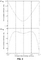
- FIG. 3 illustrates an example of graphs 40 and 42 demonstrating off-axis magnetic field in accordance with an aspect of the invention.
- the graphs 30 and 40 can correspond to a typical, substantially cylindrical magnetic solenoid having a coil radius of approximately 7.5mm and a coil length of approximately 14mm.
- the graphs 32 and 42 can correspond to the magnetic solenoid 10 in the example of FIG. 1 , such as based on Equation 1, having substantially similar dimensions as the typical, substantially cylindrical magnetic solenoid.
- the magnetic solenoid 10 can have a MinorAxis value of approximately 7.5mm, a MajorAxis value of approximately 34mm, a Midpoint value of approximately 7mm, and values for the constants A , B, and C of approximately 10 3 , 10 8 , and 4, respectively.
- a test volume of an approximately 2mm sphere centered at the midpoint of each of the magnetic solenoids is chosen.
- the graphs 30 and 32 plot changes in the magnetic field (Y-axis), in parts per million, versus distance along the central axis (X-axis) of the respective magnetic solenoids.
- the graphs 40 and 42 plot changes in the magnetic field (Y-axis), in parts per million, versus transverse distance from the central axis (X-axis) of the respective magnetic solenoids.
- the magnetic solenoid 10 has significantly greater along-axis magnetic field uniformity than the typical, cylindrical magnetic solenoid demonstrated by the graph 30.
- the graph 30 demonstrates variation in the along-axis magnetic field for the typical, substantially cylindrical magnetic solenoid of approximately 8000 parts per million relative to a variation of approximately 0.4 parts per million demonstrated by the graph 32 for the magnetic solenoid 10.
- the magnetic solenoid 10 has significantly greater off-axis magnetic field uniformity than the typical, cylindrical magnetic solenoid demonstrated by the graph 40.
- the graph 40 demonstrates variation in the off-axis magnetic field for the typical, substantially cylindrical magnetic solenoid of approximately 4000 parts per million relative to a variation of approximately 0.8 parts per million demonstrated by the graph 42 for the magnetic solenoid 10.
- the compound equation that defines the radius of the conductive coil of the magnetic solenoid 10 is not limited to Equation 1.
- R MidpointRadius ⁇ Z ⁇ Midpoint ⁇ A B C + Z ⁇ Midpoint ⁇ D E F
- the first operand of Equation 2 can provide an initial radial value
- the second and third operands of Equation 2 can be defined ( i.e., based on the constants A , B, C, D, E, and F ) to provide substantially uniform along-axis and off-axis magnitudes of the magnetic field within the inner volume 18 of the magnetic solenoid 10.
- the constants A , B, C, D, E, and F in the second and third operands, respectively can define both a substantially rounded shape of the central portion 24 along the length of the magnetic solenoid to provide a substantially uniform magnitude of the magnetic field along the central axis 20.
- the second and third operands of Equation 2 can also be defined to provide a substantially uniform off-axis magnitude of the magnetic field within the inner volume 18 of the magnetic solenoid 10.
- the constants A , B, C, D , E, and F in the second and third operands, respectively, can also define the substantially flared shape of the respective end portions 26 and 28.
- the compound equation can be expressed in any of a variety of ways to define the geometry of the conductive coil of the magnetic solenoid 10 to generate the substantially uniform magnetic field within the inner volume 18 of the magnetic solenoid 10.
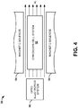
- FIG. 4 illustrates an example of a gyroscope system 50 in accordance with an aspect of the invention.
- the gyroscope system 50 can be configured as a nuclear magnetic resonance (NMR) gyroscope system, such as to detect rotational motion about an axis.
- NMR nuclear magnetic resonance
- the gyroscope system 50 can be one of a plurality of gyroscope systems, such as implemented in air or spacecraft, to detect yaw, pitch, and roll, respectively.
- the gyroscope system 50 includes a gyroscope cell system 52.
- the gyroscope cell 52 can include a glass case that can be filled with, for example, an alkali metal vapor and/or at least one noble gas isotope.
- the gyroscope cell 52 is substantially enclosed in an inner volume of a magnetic solenoid 54.
- the magnetic solenoid 54 can be configured substantially similar to the magnetic solenoid 10 in the example of FIG. 1 .
- the magnetic solenoid 54 can have a radius about a central axis that is defined by a compound equation, such as Equation 1 that includes a first operand that is a substantially circular or elliptical function and a second operand that is an exponential function ( e.g., a polynomial), or such as Equation 2 that includes a first operand that defines the radius at the center of the magnetic solenoid 54 and second and third operands that are each exponential functions. Therefore, the magnetic solenoid 54 can be configured to generate a substantially uniform magnetic field B E throughout the inner volume of the magnetic solenoid 54.
- Equation 1 that includes a first operand that is a substantially circular or elliptical function and a second operand that is an exponential function (e.g., a polynomial)
- Equation 2 that includes a first operand that defines the radius at the center of the magnetic solenoid 54 and second and third operands that are each exponential functions. Therefore, the magnetic solenoid 54 can be configured to generate a substantially
- the alkali metal vapor and the noble gas isotope(s), in the gyroscope cell 52 can precess relative to the axis of the gyroscope cell 52.
- the gyroscope system 50 also includes an opto-electronics system 56.
- the opto-electronics system 56 can be configured to optically pump the alkali metal vapor in the gyroscope cell 52 to align the spin of the alkali metal vapor with the applied magnetic field.
- any noble gas isotopes also present in the cell are also spin-aligned to the pump light beam.
- a detection beam of light with a directional component normal to the pump direction can be modulated in response to the alignment of the alkali metal vapor relative to the detection light.
- the modulation of the detection light can be a function of the precession of the alkali metal vapor as modified by the precession of any noble gas isotopes present.
- This modulation can be detected by a photodetector, such as included in the opto-electronics system 56. Accordingly, changes in the precession rates of the alkali metal vapor, and by extension any noble gas isotopes present, as detected by the modulated optical signal, can be detected and processed to determine changes in the orientation of the gyroscope cell 52 that correspond to rotational motion.
- the gyroscope system 50 is demonstrated simplistically. As such, additional components and details have been omitted from the example of FIG. 4 and the associated description.
- a magnetic solenoid such as the magnetic solenoid 10 in the example of FIG. 1 is not intended to be limited to use in a gyroscope system, such as the gyroscope system 50 in the example of FIG. 4 . Therefore, the magnetic solenoid 10 can be implemented in any of a variety of applications that may require a magnetic field, particularly a substantially uniform magnetic field.
Landscapes
- Physics & Mathematics (AREA)
- Electromagnetism (AREA)
- Engineering & Computer Science (AREA)
- Power Engineering (AREA)
- General Physics & Mathematics (AREA)
- Radar, Positioning & Navigation (AREA)
- Remote Sensing (AREA)
- Condensed Matter Physics & Semiconductors (AREA)
- Electromagnets (AREA)
- Magnetic Resonance Imaging Apparatus (AREA)
Claims (7)
- Magnetspule (10), welche eine verlängerte Seitenwand beinhaltet, welche sich zwischen voneinander entfernten Enden erstreckt, wobei die verlängerte Seitenwand eine Mittelachse (20) umgibt, welche sich in Längsrichtung entlang der Seitenwand erstreckt, wobei die verlängerte Seitenwand einen Radius besitzt, welcher durch eine zusammengesetzte Gleichung definiert wird, welche den Radius als eine Funktion der Position entlang der Mittelachse (20) variiert, wobei die zusammengesetzte Gleichung einen Abschnitt der verlängerten Seitenwand definiert, welche konkav in Bezug auf den Radius entlang der Mittelachse (20) in Bezug auf eine innere Fläche der verlängerten Seitenwand ist, dadurch gekennzeichnet, dass die zusammengesetzte Gleichung mindestens einen Abschnitt der verlängerten Seitenwand definiert, welche konvex in Bezug auf den Radius entlang der Mittelachse (20) in Bezug auf die innere Fläche der verlängerten Seitenwand ist, und dadurch, dass die Magnetspule durch ein magnetisch abschirmendes Material umschlossen ist.
- Magnetspule (10) nach Anspruch 1, bei welcher die zusammengesetzte Gleichung einen ersten Operanden und einen zweiten Operanden beinhaltet, wobei der erste Operand eine im Wesentlichen elliptische Funktion in Bezug auf den Radius entlang der Mittelachse (20) beinhaltet und eine Nebenachse besitzt, welche durch die Mittelachse (20) zweigeteilt wird und eine Hauptachse, welche kollinear in Bezug auf die Hauptachse (20) ist, und wobei der zweite Operand eine exponentielle Funktion beinhaltet, welche den Radius dazu veranlasst, sich von der Mittelachse (20) an den voneinander entfernten Enden nach außen zu erstrecken.
- Magnetspule (10) nach Anspruch 1, bei welcher die Magnetspule (10) im Wesentlichen symmetrisch in Bezug auf eine Ebene ist, welche normal zur Mittelachse (20) ist und welche einen Mittelpunkt der Magnetspule (10) entlang der Mittelachse (20) schneidet.
- Magnetspule (10) nach Anspruch 1, bei welcher die zusammengesetzte Gleichung Folgendes beinhaltet:einen ersten Operanden, welcher den Radius an einem Mittelpunkt der Magnetspule (10) entlang der Mittelachse (20) definiert;einen zweiten Operanden, welcher eine exponentielle Funktion ist, welche vom ersten Operanden subtrahiert wird; undeinen dritten Operanden, welcher eine exponentielle Funktion ist, welche dem ersten Operanden hinzuaddiert wird, wobei der zweite und der dritte Operand einander entgegenwirken, um den Radius entlang der Mittelachse (20) vom Mittelpunkt aus zu variieren.
- Magnetspule (10) nach Anspruch 1, bei welcher der Radius R durch Folgendes definiert wird:
 Nebenachse eine Nebenachsenabmessung eines elliptischen Abschnittes der zusammengesetzten Gleichung ist;Hauptachse eine Hauptachsenabmessung des elliptischen Abschnittes der zusammengesetzten Gleichung ist;Z eine Distanz entlang der Mittelachse (20) in Bezug auf ein erstes Ende der Magnetspule (10) ist;Mittelpunkt eine Distanz entlang der Mittelachse (20) vom ersten Ende der Magnetspule (10) bis zu einem Mittelpunt der Magnetspule (10) entlang der Mittelachse (20) ist; undA, B, und C Konstanten ungleich null sind, welche einen exponentiellen Abschnitt der zusammengesetzten Gleichung definieren.
 - Magnetspule (10) nach Anspruch 1, bei welcher der Radius R durch Folgendes definiert wird:
 Mittelpunkt-Radius ein Radius an einem Mittelpunkt der Magnetspule (10) entlang der Mittelachse (20) ist;Z eine Distanz entlang der Mittelachse (20) in Bezug auf ein erstes Ende der Magnetspule (10) ist;Mittelpunkt eine Distanz entlang der Mittelachse (20) vom ersten Ende der Magnetspule (10) bis zum Mittelpunt der Magnetspule (10) entlang der Mittelachse (20) ist; undA, B, und C, D, E und F Konstanten ungleich null sind, welche die jeweiligen exponentiellen Abschnitte der zusammengesetzten Gleichung definieren.
 - Gyroskopsystem, welches die Magnetspule (10) nach Anspruch 1 beinhaltet, wobei das Gyroskopsystem eine Gyroskopzelle beinhaltet, welche innerhalb des inneren Volumens (18) der Magnetspule (10) eingeschlossen ist.
Applications Claiming Priority (2)
| Application Number | Priority Date | Filing Date | Title |
|---|---|---|---|
| US12/364,189 US8330566B2 (en) | 2009-02-02 | 2009-02-02 | Magnetic solenoid for generating a substantially uniform magnetic field |
| PCT/US2010/022901 WO2010088675A1 (en) | 2009-02-02 | 2010-02-02 | Magnetic solenoid for generating a substantially uniform magnetic field |
Publications (3)
| Publication Number | Publication Date |
|---|---|
| EP2392015A1 EP2392015A1 (de) | 2011-12-07 |
| EP2392015A4 EP2392015A4 (de) | 2017-03-15 |
| EP2392015B1 true EP2392015B1 (de) | 2019-07-03 |
Family
ID=42396083
Family Applications (1)
| Application Number | Title | Priority Date | Filing Date |
|---|---|---|---|
| EP10736573.6A Active EP2392015B1 (de) | 2009-02-02 | 2010-02-02 | Elektromagnet zur erzeugung eines substantiell gleichförmigen magnetfeldes |
Country Status (4)
| Country | Link |
|---|---|
| US (1) | US8330566B2 (de) |
| EP (1) | EP2392015B1 (de) |
| JP (1) | JP5575811B2 (de) |
| WO (1) | WO2010088675A1 (de) |
Cited By (1)
| Publication number | Priority date | Publication date | Assignee | Title |
|---|---|---|---|---|
| RU2802341C1 (ru) * | 2023-01-24 | 2023-08-25 | Акционерное общество "Концерн "Центральный научно-исследовательский институт "Электроприбор" | Способ одновременной генерации магнитного поля и термостабилизации квантового датчика вращения и устройство для его реализации |
Families Citing this family (5)
| Publication number | Priority date | Publication date | Assignee | Title |
|---|---|---|---|---|
| US8487729B2 (en) * | 2009-02-02 | 2013-07-16 | Northrop Grumman Guidance & Electronics | Magnetic solenoid for generating a substantially uniform magnetic field |
| US10782368B2 (en) | 2017-05-31 | 2020-09-22 | Northrop Grumman Systems Corporation | Pulsed-beam atomic magnetometer system |
| CN109489650A (zh) * | 2018-10-31 | 2019-03-19 | 中国人民解放军国防科技大学 | 一种提供核磁共振陀螺三轴均匀磁场的柔性pcb线圈 |
| US11133117B2 (en) | 2019-05-08 | 2021-09-28 | Northrop Grumman Systems Corporation | Atomic interferometer system |
| CN110514192A (zh) * | 2019-08-13 | 2019-11-29 | 中国航空工业集团公司西安飞行自动控制研究所 | 一种磁场产生装置 |
Family Cites Families (15)
| Publication number | Priority date | Publication date | Assignee | Title |
|---|---|---|---|---|
| US2159534A (en) * | 1935-07-23 | 1939-05-23 | Firm Fernseh Ag | Cathode ray focusing coil |
| US2438985A (en) * | 1945-02-26 | 1948-04-06 | Anthony A Ambrose | Electromagnet |
| US4063207A (en) * | 1977-01-31 | 1977-12-13 | Litton Systems, Inc. | Coil structure |
| JPS57172704A (en) | 1981-04-17 | 1982-10-23 | Hitachi Ltd | Superconductive solenoid coil |
| US4651565A (en) | 1984-07-05 | 1987-03-24 | The Charles Stark Draper Laboratory, Inc. | Electromagnetic gyroscope |
| JPS6182404A (ja) * | 1984-09-29 | 1986-04-26 | Toshiba Corp | 超電導マグネツト |
| US5117188A (en) * | 1990-10-29 | 1992-05-26 | General Atomics | Quasi-open magnet configuration for use in magnetic resonance imaging |
| JPH0996666A (ja) * | 1995-09-29 | 1997-04-08 | Sony Corp | 磁気センサ |
| US5799653A (en) * | 1995-10-03 | 1998-09-01 | Toshiba America Mri, Inc. | Magnetic resonance imaging apparatus with decreased patient claustrophobia and increased access to patient |
| US6198369B1 (en) * | 1998-12-04 | 2001-03-06 | Tlx Technologies | Proportional actuator for proportional control devices |
| JP3777962B2 (ja) * | 2000-09-14 | 2006-05-24 | 松下電工株式会社 | 電磁装置及び高電圧発生装置 |
| AU2001286255A1 (en) * | 2000-09-14 | 2002-03-26 | Matsushita Electric Works Ltd. | Electromagnetic device and high-voltage generating device and method of producing electromagnetic device |
| US20030058077A1 (en) * | 2001-09-21 | 2003-03-27 | Colin Hamer | Ignition coil and method of making |
| JP4506078B2 (ja) * | 2002-12-24 | 2010-07-21 | パナソニック電工株式会社 | 電磁装置および高電圧発生装置 |
| DE102008060757A1 (de) * | 2008-12-05 | 2010-06-17 | Forschungszentrum Jülich GmbH | Vorrichtung zur Erzeugung eines homogenen Magnetfeldes und Optimierungsverfahren |
-
2009
- 2009-02-02 US US12/364,189 patent/US8330566B2/en active Active
-
2010
- 2010-02-02 JP JP2011548405A patent/JP5575811B2/ja active Active
- 2010-02-02 EP EP10736573.6A patent/EP2392015B1/de active Active
- 2010-02-02 WO PCT/US2010/022901 patent/WO2010088675A1/en not_active Ceased
Non-Patent Citations (1)
| Title |
|---|
| None * |
Cited By (1)
| Publication number | Priority date | Publication date | Assignee | Title |
|---|---|---|---|---|
| RU2802341C1 (ru) * | 2023-01-24 | 2023-08-25 | Акционерное общество "Концерн "Центральный научно-исследовательский институт "Электроприбор" | Способ одновременной генерации магнитного поля и термостабилизации квантового датчика вращения и устройство для его реализации |
Also Published As
| Publication number | Publication date |
|---|---|
| EP2392015A4 (de) | 2017-03-15 |
| JP2012517108A (ja) | 2012-07-26 |
| JP5575811B2 (ja) | 2014-08-20 |
| US20100194506A1 (en) | 2010-08-05 |
| WO2010088675A1 (en) | 2010-08-05 |
| EP2392015A1 (de) | 2011-12-07 |
| US8330566B2 (en) | 2012-12-11 |
Similar Documents
| Publication | Publication Date | Title |
|---|---|---|
| EP2392015B1 (de) | Elektromagnet zur erzeugung eines substantiell gleichförmigen magnetfeldes | |
| EP2724353B1 (de) | Elektromagnet zur erzeugung eines substantiell gleichförmigen magnetfeldes | |
| US20240120138A1 (en) | Lightweight asymmetric magnet arrays with mixed-phase magnet rings | |
| CN110857970B (zh) | 磁体组件以及用于制造磁体组件的方法 | |
| US12205765B2 (en) | Lightweight asymmetric array of magnet elements | |
| CN115979409B (zh) | 基于磁流体动力学的角振动传感器及角振动探测方法 | |
| CN111009374A (zh) | 一种具有紧凑线圈结构的核磁共振超导磁体 | |
| EP0460762A1 (de) | Magnetsystem für Kernspinresonanz | |
| CN105990631A (zh) | 用于小磁体气隙的epr微波腔体 | |
| JP4118833B2 (ja) | Mri用コイル | |
| JP2013125998A (ja) | ループアンテナ | |
| US20150137814A1 (en) | Gradient magnetic field coil device and magnetic resonance imaging device | |
| US10690738B1 (en) | Lightweight asymmetric magnet arrays | |
| Caprari | Optimal current loop systems for producing uniform magnetic fields | |
| US11004650B2 (en) | Multipole lens, aberration corrector using the same, and charged particle beam apparatus | |
| US9921279B2 (en) | Magnetic resonance imaging device | |
| US20090309682A1 (en) | Eight-fold dipole magnet array for generating a uniform magnetic field | |
| US6954070B2 (en) | NMR imaging system with conical permanent magnet | |
| 会社ー | i, United States Patent (10) Patent No.: US 8,487,729 B2 | |
| Mikhailichenko | Some peculiarities of Magnetic Field Behavior in Dual Bore Magnets | |
| RU2247322C2 (ru) | Магнитный компас | |
| KR20100014014A (ko) | 변형된 요크를 구비하는 쌍극자 자석 장치 |
Legal Events
| Date | Code | Title | Description |
|---|---|---|---|
| PUAI | Public reference made under article 153(3) epc to a published international application that has entered the european phase |
Free format text: ORIGINAL CODE: 0009012 |
|
| 17P | Request for examination filed |
Effective date: 20110801 |
|
| AK | Designated contracting states |
Kind code of ref document: A1 Designated state(s): AT BE BG CH CY CZ DE DK EE ES FI FR GB GR HR HU IE IS IT LI LT LU LV MC MK MT NL NO PL PT RO SE SI SK SM TR |
|
| DAX | Request for extension of the european patent (deleted) | ||
| RA4 | Supplementary search report drawn up and despatched (corrected) |
Effective date: 20170209 |
|
| RIC1 | Information provided on ipc code assigned before grant |
Ipc: H01F 7/06 20060101AFI20170203BHEP |
|
| STAA | Information on the status of an ep patent application or granted ep patent |
Free format text: STATUS: EXAMINATION IS IN PROGRESS |
|
| 17Q | First examination report despatched |
Effective date: 20180328 |
|
| GRAP | Despatch of communication of intention to grant a patent |
Free format text: ORIGINAL CODE: EPIDOSNIGR1 |
|
| STAA | Information on the status of an ep patent application or granted ep patent |
Free format text: STATUS: GRANT OF PATENT IS INTENDED |
|
| INTG | Intention to grant announced |
Effective date: 20190318 |
|
| RAP1 | Party data changed (applicant data changed or rights of an application transferred) |
Owner name: NORTHROP GRUMMAN GUIDANCE AND ELECTRONICS COMPANY, |
|
| GRAS | Grant fee paid |
Free format text: ORIGINAL CODE: EPIDOSNIGR3 |
|
| GRAA | (expected) grant |
Free format text: ORIGINAL CODE: 0009210 |
|
| STAA | Information on the status of an ep patent application or granted ep patent |
Free format text: STATUS: THE PATENT HAS BEEN GRANTED |
|
| AK | Designated contracting states |
Kind code of ref document: B1 Designated state(s): AT BE BG CH CY CZ DE DK EE ES FI FR GB GR HR HU IE IS IT LI LT LU LV MC MK MT NL NO PL PT RO SE SI SK SM TR |
|
| REG | Reference to a national code |
Ref country code: GB Ref legal event code: FG4D |
|
| REG | Reference to a national code |
Ref country code: CH Ref legal event code: EP Ref country code: AT Ref legal event code: REF Ref document number: 1151972 Country of ref document: AT Kind code of ref document: T Effective date: 20190715 |
|
| REG | Reference to a national code |
Ref country code: DE Ref legal event code: R096 Ref document number: 602010059830 Country of ref document: DE |
|
| REG | Reference to a national code |
Ref country code: IE Ref legal event code: FG4D |
|
| REG | Reference to a national code |
Ref country code: NL Ref legal event code: MP Effective date: 20190703 |
|
| REG | Reference to a national code |
Ref country code: LT Ref legal event code: MG4D |
|
| REG | Reference to a national code |
Ref country code: AT Ref legal event code: MK05 Ref document number: 1151972 Country of ref document: AT Kind code of ref document: T Effective date: 20190703 |
|
| PG25 | Lapsed in a contracting state [announced via postgrant information from national office to epo] |
Ref country code: PT Free format text: LAPSE BECAUSE OF FAILURE TO SUBMIT A TRANSLATION OF THE DESCRIPTION OR TO PAY THE FEE WITHIN THE PRESCRIBED TIME-LIMIT Effective date: 20191104 Ref country code: HR Free format text: LAPSE BECAUSE OF FAILURE TO SUBMIT A TRANSLATION OF THE DESCRIPTION OR TO PAY THE FEE WITHIN THE PRESCRIBED TIME-LIMIT Effective date: 20190703 Ref country code: AT Free format text: LAPSE BECAUSE OF FAILURE TO SUBMIT A TRANSLATION OF THE DESCRIPTION OR TO PAY THE FEE WITHIN THE PRESCRIBED TIME-LIMIT Effective date: 20190703 Ref country code: LT Free format text: LAPSE BECAUSE OF FAILURE TO SUBMIT A TRANSLATION OF THE DESCRIPTION OR TO PAY THE FEE WITHIN THE PRESCRIBED TIME-LIMIT Effective date: 20190703 Ref country code: BG Free format text: LAPSE BECAUSE OF FAILURE TO SUBMIT A TRANSLATION OF THE DESCRIPTION OR TO PAY THE FEE WITHIN THE PRESCRIBED TIME-LIMIT Effective date: 20191003 Ref country code: NL Free format text: LAPSE BECAUSE OF FAILURE TO SUBMIT A TRANSLATION OF THE DESCRIPTION OR TO PAY THE FEE WITHIN THE PRESCRIBED TIME-LIMIT Effective date: 20190703 Ref country code: SE Free format text: LAPSE BECAUSE OF FAILURE TO SUBMIT A TRANSLATION OF THE DESCRIPTION OR TO PAY THE FEE WITHIN THE PRESCRIBED TIME-LIMIT Effective date: 20190703 Ref country code: FI Free format text: LAPSE BECAUSE OF FAILURE TO SUBMIT A TRANSLATION OF THE DESCRIPTION OR TO PAY THE FEE WITHIN THE PRESCRIBED TIME-LIMIT Effective date: 20190703 Ref country code: NO Free format text: LAPSE BECAUSE OF FAILURE TO SUBMIT A TRANSLATION OF THE DESCRIPTION OR TO PAY THE FEE WITHIN THE PRESCRIBED TIME-LIMIT Effective date: 20191003 Ref country code: CZ Free format text: LAPSE BECAUSE OF FAILURE TO SUBMIT A TRANSLATION OF THE DESCRIPTION OR TO PAY THE FEE WITHIN THE PRESCRIBED TIME-LIMIT Effective date: 20190703 |
|
| PG25 | Lapsed in a contracting state [announced via postgrant information from national office to epo] |
Ref country code: LV Free format text: LAPSE BECAUSE OF FAILURE TO SUBMIT A TRANSLATION OF THE DESCRIPTION OR TO PAY THE FEE WITHIN THE PRESCRIBED TIME-LIMIT Effective date: 20190703 Ref country code: IS Free format text: LAPSE BECAUSE OF FAILURE TO SUBMIT A TRANSLATION OF THE DESCRIPTION OR TO PAY THE FEE WITHIN THE PRESCRIBED TIME-LIMIT Effective date: 20191103 Ref country code: GR Free format text: LAPSE BECAUSE OF FAILURE TO SUBMIT A TRANSLATION OF THE DESCRIPTION OR TO PAY THE FEE WITHIN THE PRESCRIBED TIME-LIMIT Effective date: 20191004 Ref country code: ES Free format text: LAPSE BECAUSE OF FAILURE TO SUBMIT A TRANSLATION OF THE DESCRIPTION OR TO PAY THE FEE WITHIN THE PRESCRIBED TIME-LIMIT Effective date: 20190703 |
|
| PG25 | Lapsed in a contracting state [announced via postgrant information from national office to epo] |
Ref country code: TR Free format text: LAPSE BECAUSE OF FAILURE TO SUBMIT A TRANSLATION OF THE DESCRIPTION OR TO PAY THE FEE WITHIN THE PRESCRIBED TIME-LIMIT Effective date: 20190703 |
|
| PG25 | Lapsed in a contracting state [announced via postgrant information from national office to epo] |
Ref country code: DK Free format text: LAPSE BECAUSE OF FAILURE TO SUBMIT A TRANSLATION OF THE DESCRIPTION OR TO PAY THE FEE WITHIN THE PRESCRIBED TIME-LIMIT Effective date: 20190703 Ref country code: PL Free format text: LAPSE BECAUSE OF FAILURE TO SUBMIT A TRANSLATION OF THE DESCRIPTION OR TO PAY THE FEE WITHIN THE PRESCRIBED TIME-LIMIT Effective date: 20190703 Ref country code: RO Free format text: LAPSE BECAUSE OF FAILURE TO SUBMIT A TRANSLATION OF THE DESCRIPTION OR TO PAY THE FEE WITHIN THE PRESCRIBED TIME-LIMIT Effective date: 20190703 Ref country code: EE Free format text: LAPSE BECAUSE OF FAILURE TO SUBMIT A TRANSLATION OF THE DESCRIPTION OR TO PAY THE FEE WITHIN THE PRESCRIBED TIME-LIMIT Effective date: 20190703 |
|
| PG25 | Lapsed in a contracting state [announced via postgrant information from national office to epo] |
Ref country code: SM Free format text: LAPSE BECAUSE OF FAILURE TO SUBMIT A TRANSLATION OF THE DESCRIPTION OR TO PAY THE FEE WITHIN THE PRESCRIBED TIME-LIMIT Effective date: 20190703 Ref country code: IS Free format text: LAPSE BECAUSE OF FAILURE TO SUBMIT A TRANSLATION OF THE DESCRIPTION OR TO PAY THE FEE WITHIN THE PRESCRIBED TIME-LIMIT Effective date: 20200224 Ref country code: SK Free format text: LAPSE BECAUSE OF FAILURE TO SUBMIT A TRANSLATION OF THE DESCRIPTION OR TO PAY THE FEE WITHIN THE PRESCRIBED TIME-LIMIT Effective date: 20190703 |
|
| REG | Reference to a national code |
Ref country code: DE Ref legal event code: R097 Ref document number: 602010059830 Country of ref document: DE |
|
| PLBE | No opposition filed within time limit |
Free format text: ORIGINAL CODE: 0009261 |
|
| STAA | Information on the status of an ep patent application or granted ep patent |
Free format text: STATUS: NO OPPOSITION FILED WITHIN TIME LIMIT |
|
| PG2D | Information on lapse in contracting state deleted |
Ref country code: IS |
|
| 26N | No opposition filed |
Effective date: 20200603 |
|
| PG25 | Lapsed in a contracting state [announced via postgrant information from national office to epo] |
Ref country code: SI Free format text: LAPSE BECAUSE OF FAILURE TO SUBMIT A TRANSLATION OF THE DESCRIPTION OR TO PAY THE FEE WITHIN THE PRESCRIBED TIME-LIMIT Effective date: 20190703 |
|
| REG | Reference to a national code |
Ref country code: CH Ref legal event code: PL |
|
| REG | Reference to a national code |
Ref country code: BE Ref legal event code: MM Effective date: 20200229 |
|
| PG25 | Lapsed in a contracting state [announced via postgrant information from national office to epo] |
Ref country code: MC Free format text: LAPSE BECAUSE OF FAILURE TO SUBMIT A TRANSLATION OF THE DESCRIPTION OR TO PAY THE FEE WITHIN THE PRESCRIBED TIME-LIMIT Effective date: 20190703 Ref country code: LU Free format text: LAPSE BECAUSE OF NON-PAYMENT OF DUE FEES Effective date: 20200202 |
|
| PG25 | Lapsed in a contracting state [announced via postgrant information from national office to epo] |
Ref country code: LI Free format text: LAPSE BECAUSE OF NON-PAYMENT OF DUE FEES Effective date: 20200229 Ref country code: CH Free format text: LAPSE BECAUSE OF NON-PAYMENT OF DUE FEES Effective date: 20200229 |
|
| PG25 | Lapsed in a contracting state [announced via postgrant information from national office to epo] |
Ref country code: IE Free format text: LAPSE BECAUSE OF NON-PAYMENT OF DUE FEES Effective date: 20200202 |
|
| PG25 | Lapsed in a contracting state [announced via postgrant information from national office to epo] |
Ref country code: BE Free format text: LAPSE BECAUSE OF NON-PAYMENT OF DUE FEES Effective date: 20200229 |
|
| PG25 | Lapsed in a contracting state [announced via postgrant information from national office to epo] |
Ref country code: MT Free format text: LAPSE BECAUSE OF FAILURE TO SUBMIT A TRANSLATION OF THE DESCRIPTION OR TO PAY THE FEE WITHIN THE PRESCRIBED TIME-LIMIT Effective date: 20190703 Ref country code: CY Free format text: LAPSE BECAUSE OF FAILURE TO SUBMIT A TRANSLATION OF THE DESCRIPTION OR TO PAY THE FEE WITHIN THE PRESCRIBED TIME-LIMIT Effective date: 20190703 |
|
| PG25 | Lapsed in a contracting state [announced via postgrant information from national office to epo] |
Ref country code: MK Free format text: LAPSE BECAUSE OF FAILURE TO SUBMIT A TRANSLATION OF THE DESCRIPTION OR TO PAY THE FEE WITHIN THE PRESCRIBED TIME-LIMIT Effective date: 20190703 |
|
| P01 | Opt-out of the competence of the unified patent court (upc) registered |
Effective date: 20230607 |
|
| PGFP | Annual fee paid to national office [announced via postgrant information from national office to epo] |
Ref country code: GB Payment date: 20260219 Year of fee payment: 17 |
|
| PGFP | Annual fee paid to national office [announced via postgrant information from national office to epo] |
Ref country code: DE Payment date: 20260218 Year of fee payment: 17 |
|
| PGFP | Annual fee paid to national office [announced via postgrant information from national office to epo] |
Ref country code: IT Payment date: 20260224 Year of fee payment: 17 |
|
| PGFP | Annual fee paid to national office [announced via postgrant information from national office to epo] |
Ref country code: FR Payment date: 20260218 Year of fee payment: 17 |