EP2391845B1 - Endstück für einen wellschlauch und teilesatz mit einem solchen endstück - Google Patents
Endstück für einen wellschlauch und teilesatz mit einem solchen endstück Download PDFInfo
- Publication number
- EP2391845B1 EP2391845B1 EP10742779.1A EP10742779A EP2391845B1 EP 2391845 B1 EP2391845 B1 EP 2391845B1 EP 10742779 A EP10742779 A EP 10742779A EP 2391845 B1 EP2391845 B1 EP 2391845B1
- Authority
- EP
- European Patent Office
- Prior art keywords
- socket
- end piece
- corrugated tube
- securing sleeve
- groove
- Prior art date
- Legal status (The legal status is an assumption and is not a legal conclusion. Google has not performed a legal analysis and makes no representation as to the accuracy of the status listed.)
- Not-in-force
Links
- 210000002105 tongue Anatomy 0.000 claims description 26
- 238000006073 displacement reaction Methods 0.000 claims description 11
- 230000006378 damage Effects 0.000 description 6
- 238000009434 installation Methods 0.000 description 4
- 208000027418 Wounds and injury Diseases 0.000 description 3
- 238000010276 construction Methods 0.000 description 3
- 238000005516 engineering process Methods 0.000 description 3
- 208000014674 injury Diseases 0.000 description 3
- 239000002184 metal Substances 0.000 description 2
- 230000001419 dependent effect Effects 0.000 description 1
- 230000000694 effects Effects 0.000 description 1
- 239000000463 material Substances 0.000 description 1
- 230000001681 protective effect Effects 0.000 description 1
- 230000006641 stabilisation Effects 0.000 description 1
- 238000011105 stabilization Methods 0.000 description 1
- 230000007704 transition Effects 0.000 description 1
- 238000011179 visual inspection Methods 0.000 description 1
Images

Classifications
-
- F—MECHANICAL ENGINEERING; LIGHTING; HEATING; WEAPONS; BLASTING
- F16—ENGINEERING ELEMENTS AND UNITS; GENERAL MEASURES FOR PRODUCING AND MAINTAINING EFFECTIVE FUNCTIONING OF MACHINES OR INSTALLATIONS; THERMAL INSULATION IN GENERAL
- F16L—PIPES; JOINTS OR FITTINGS FOR PIPES; SUPPORTS FOR PIPES, CABLES OR PROTECTIVE TUBING; MEANS FOR THERMAL INSULATION IN GENERAL
- F16L25/00—Construction or details of pipe joints not provided for in, or of interest apart from, groups F16L13/00 - F16L23/00
- F16L25/0036—Joints for corrugated pipes
- F16L25/0045—Joints for corrugated pipes of the quick-acting type
-
- F—MECHANICAL ENGINEERING; LIGHTING; HEATING; WEAPONS; BLASTING
- F16—ENGINEERING ELEMENTS AND UNITS; GENERAL MEASURES FOR PRODUCING AND MAINTAINING EFFECTIVE FUNCTIONING OF MACHINES OR INSTALLATIONS; THERMAL INSULATION IN GENERAL
- F16L—PIPES; JOINTS OR FITTINGS FOR PIPES; SUPPORTS FOR PIPES, CABLES OR PROTECTIVE TUBING; MEANS FOR THERMAL INSULATION IN GENERAL
- F16L33/00—Arrangements for connecting hoses to rigid members; Rigid hose-connectors, i.e. single members engaging both hoses
- F16L33/26—Arrangements for connecting hoses to rigid members; Rigid hose-connectors, i.e. single members engaging both hoses specially adapted for hoses made of metal
-
- F—MECHANICAL ENGINEERING; LIGHTING; HEATING; WEAPONS; BLASTING
- F16—ENGINEERING ELEMENTS AND UNITS; GENERAL MEASURES FOR PRODUCING AND MAINTAINING EFFECTIVE FUNCTIONING OF MACHINES OR INSTALLATIONS; THERMAL INSULATION IN GENERAL
- F16L—PIPES; JOINTS OR FITTINGS FOR PIPES; SUPPORTS FOR PIPES, CABLES OR PROTECTIVE TUBING; MEANS FOR THERMAL INSULATION IN GENERAL
- F16L33/00—Arrangements for connecting hoses to rigid members; Rigid hose-connectors, i.e. single members engaging both hoses
- F16L33/30—Arrangements for connecting hoses to rigid members; Rigid hose-connectors, i.e. single members engaging both hoses comprising parts inside the hoses only
-
- H—ELECTRICITY
- H02—GENERATION; CONVERSION OR DISTRIBUTION OF ELECTRIC POWER
- H02G—INSTALLATION OF ELECTRIC CABLES OR LINES, OR OF COMBINED OPTICAL AND ELECTRIC CABLES OR LINES
- H02G3/00—Installations of electric cables or lines or protective tubing therefor in or on buildings, equivalent structures or vehicles
- H02G3/02—Details
- H02G3/04—Protective tubing or conduits, e.g. cable ladders or cable troughs
- H02G3/0406—Details thereof
Definitions
- the invention relates to an end piece for placement on a free end of a corrugated tube and a parts set with such a tail.
- Corrugated hoses or corrugated pipes are used in many places as a protective tube for an actual use carrier such as cables or pipes.
- corrugated hoses made of metal or plastic are used. While mainly corrugated hoses made of plastic are used for cable ducts in building technology, mainly corrugated hoses made of metal are used in nuclear power plant technology due to the radiation exposure occurring there.
- the corrugated tubes are cut to the appropriate length. When cutting off the corrugated hose resulting in sharp edges at its free ends. These pose a risk of injury to the assembly worker, and may also cause cables received from the corrugated hose to be chafed through these sharp cutting edges.
- building and nuclear power plant technology concerns this problem and robots and other machines in which cables are fed in a corrugated hose a moving component.
- Object of the present invention is to provide an end piece for a corrugated hose and a set of parts with such a tail, with the help of the outgoing of the sharp-edged free ends of the corrugated tube dangers can be reduced and which is easy to install.
- the tail according to the invention for placing on a free end of a corrugated hose comprises a bushing, with a free end of the corrugated tube facing the front region and a front region in a longitudinal direction of the sleeve opposite rear portion which is in the mounted state of the sleeve within the corrugated hose.
- the front portion of the sleeve consists of a collar which at least partially surrounds the free end of the corrugated tube, radially projecting in the direction of an outer space not surrounded by the socket and extending along the circumference of the socket, in the longitudinal direction of the socket opening groove for at least partially receiving the free end of the corrugated tube forms.
- the longitudinal region of the front region opposite rear portion of the bush consists of a plurality of spring tongues. These have a relief direction oriented perpendicular to the longitudinal direction of the bush and directed in the direction of the outer space of the bushing. At least a part of the spring tongues is provided with at least one arranged on an outer side facing the outer side of the respective spring tongue and radially projecting latching projection for the realization of an effective in the longitudinal direction of the bushing rear grip.
- the end piece according to the invention also comprises a locking sleeve which can be received by the socket and, in the assembled state of the end piece, viewed in the longitudinal direction, extends in at least part of the rear area of the socket in an inner space enclosed by the socket. This locking sleeve limits the radial play of the spring tongues in the direction of the interior of the socket.
- the advantage of the end piece according to the invention is that this can be mounted easily and completely without additional tools.
- the end piece according to the invention is secured against accidental removal from the corrugated tube, which greatly simplifies the laying of the corrugated tube.
- the locking sleeve is accurately received by the socket.
- the securing sleeve limits the radial clearance of the spring tongues to a distance which is smaller than the radial extent of the latching projections in the direction of the outer space of the bushing.
- the radial extent of the latching protrusions is measured between an outer side of the bush facing the outer space and a free end of the latching protrusions.
- the securing sleeve extends from the rear region of the bushing along an inner side of the bush facing the interior of the bushing into the front region of the bushing.
- the socket is almost completely penetrated by the locking sleeve. This measure contributes to the mechanical Stabilization of the socket, in particular, the rear portion of the socket, which consists of a plurality of spring tongues, completely stabilized by the existing in the interior of the bushing locking sleeve, so that a reliable backup of the spring tongues is ensured.
- the securing sleeve is held displaceably in the bush. It is desirable to secure the locking sleeve both against displacement in the direction of the rear region and against displacement in the direction of the front region of the socket.
- a displacement of the locking sleeve in the direction of the rear portion of the socket is prevented by a stop present on the socket.
- This stop ensures that when mounting the locking sleeve it is not accidentally pushed too far into the socket. In such a case, the securing of the end piece might no longer be guaranteed, the end piece would have to be removed again and the corrugated hose possibly cut again. Such a stop thus improves the handling of the tail.
- the stop between a at the rear end of the sleeve in the radial direction in the direction of the interior of the sleeve extending projection and the rear end of the socket facing free end of the securing sleeve is made.
- the spring tongues are secured with such a stop next to the locking sleeve.
- the proposed end piece serves to prevent damage to the guided in the corrugated hose cable.
- the tail itself should bring no new sources of danger for the guided cable with it.
- the protrusion extending in the direction of the interior of the bushing and the inside of the securing sleeve form-fittingly close off. A facing the interior sharp edge can thus be effectively avoided, whereby the risk of damage to the guided inside the corrugated hose cables can be substantially reduced.
- the securing sleeve is secured against displacement in the direction of the rear region of the bushing by means of a stop which is present between a front end face of the collar, radially encircling free rotation and one at the front free end of the securing sleeve , radially projecting in the direction of the outer space flange is made.
- the installer can easily determine whether the attack in question is present or not.
- the accurate fit of the locking sleeve can be determined by simple visual inspection.
- the end face of the flange and the end face of the collar are flush. The risk of injury to the ausmündenden from the tail cable and for a fitter who handled after placing the tail on the corrugated hose with this, can be significantly reduced.
- the securing sleeve is secured against displacement in the direction of the front region of the bushing by a rear grip of at least one spring element present on the securing sleeve, which engages in a groove provided on the bushing.
- the spring element provided on the safety bushing has a direction of relief directed in the direction of the outer space.
- the existing in the socket groove is open in this case in the direction of the interior.
- the spring element does not protrude into the interior of the locking sleeve, so that this also represents no risk of damage to the guided in the interior of the cable.
- the groove radially recirculated into the socket.
- the latching projections on a chamfer which extends starting at their free ends in the direction of the rear portion of the socket.
- the set of parts according to the invention consists of a corrugated tube and an end piece explained above.
- the extension of the radially projecting latching projections of this end piece is smaller in the longitudinal direction than that between adjacent corrugations of the corrugated hose - measured on the inside of the corrugated hose - existing free space.
- the extension of the latching projections in the longitudinal direction of the end piece is adapted to the internal spacing of the corrugations of the corrugated hose. Corrugated hose and tail are so matched.
- the collar of the end piece has a radially encircling, extending in the direction of the rear portion of the sleeve outer shell, which limits the groove in the direction of the outer space.
- This outer shell is now dimensioned such that the distance between a bottom of the groove and a free end of the outer shell is greater than the distance between adjacent corrugations of the corrugated hose.
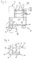
- Fig. 1 shows an end piece 2, which is placed on a free end 4 of a corrugated tube 6.
- the end piece 2 is up to its center axis M, which extends in a longitudinal direction L of the end piece 2, on the in Fig. 1 cut half shown below and shown in top half in plan view.
- the end piece 2 consists of a socket 8, which receives a locking sleeve 10 accurately.
- this consists of a collar 14 which forms a groove 16 for receiving the free end 4 of the corrugated tube 6.
- the groove 16 is bounded by an outer jacket 18.
- the bushing 8 In a the front portion 12 in the longitudinal direction L of the bush 8 opposite rear portion 20, which is located in the assembled state of the end piece 2 within the corrugated tube 6, the bushing 8 consists of a plurality of spring tongues 22. These spring tongues 22 have a in the direction of Outside on the bushing 8 directed relief direction. On its outer side facing the outer space 24 are radially projecting latching projections 26. With the help of these locking projections 26 a rearward engagement between one of the shafts 28 of the corrugated hose 6 and the bushing 8 is produced in the longitudinal direction L.
- the socket 8 encloses a Interior IN, in this extends substantially over the entire length of the sleeve 8, the securing sleeve 10.
- the locking sleeve 10 is fitted snugly into the socket 8. It limits the radial clearance of the spring tongues 22 in the direction of the interior IN to a distance that is smaller than the radial extent BR (see. Fig. 2 ) of the latching projections 26 in the direction of the outer space AN of the bushing 8.
- the radial extent BR of the latching projections 26 is measured starting from a exterior space 24 facing the outer side 24 of the spring tongues 22 and a free end of the corresponding spring tongue 26.
- the locking sleeve 10 is held against displacement in the socket 8. In principle, it would be possible to ensure the displacement safety by a friction fit of the locking sleeve 10 in the socket 8. In the present embodiment, however, the securing sleeve 10 is secured against displacement in the direction of the rear region 20 of the bushing 8 by a stop which is present between the bushing 8 and the securing sleeve 10. This stop is located between a radially extending in the direction of the inner space IN of the bushing 8 projection 30 and a voltage applied in the rear portion 20 of the socket 8 free end of the locking sleeve 10. In order for the in the interior IN of the tail 2 and within the corrugated tube 6 out Cable exclude any risk of injury, closes the inside 32 of the locking sleeve 10 with the projection 30 form-fitting.
- the locking sleeve 10 is secured by means of a spring element 40.
- This spring element 40 engages in a recessed into the inside of the socket 8 securing groove 42, which is open in the direction of the interior IN.
- the spring element 40 which is integrally formed on the securing sleeve 10, has a relief direction directed in the direction of the exterior space AN.
- the securing groove 42 extends radially circumferentially in the socket 8, and thus secures a lubinditionn seat of the locking sleeve 10 in the socket. 8
- Fig. 2 that already shows Fig. 1 known socket 8 alone, wherein in the lower part of the representation, this is shown in a longitudinal section and in the upper part in plan view.
- the spring tongues 22 are integrally formed on the bushing 8, to ensure their flexibility in the radial direction, located in the region of the transition between the actual body of the respective spring tongue 22 and the sleeve 8 a taper 44. Also clearly visible is the radially on the inside the sleeve 8 circumferential securing groove 42 into which the spring element 40 of the locking sleeve 10 engages.
- Fig. 3 shows an enlarged view of the in Fig. 2 according to marked section. Clearly visible is the to Recording the Freiendes 4 of the corrugated tube 6 provided groove 16, as well as the elasticity of the spring tongues 22 ensuring taper 44.
- the radially outer circumferential jacket 18 of the collar 14 defines the groove 16 in the radial direction.
- the height 52 of the outer sheath 18 in the longitudinal direction L which is measured between a bottom 48 of the groove 16 and a free end 50 of the outer sheath 18, is greater than the distance 54 (see FIG. Fig. 1 ) adjacent shafts 28 of the corrugated tube 6 is selected. This dimensioning of the outer jacket 18 ensures that the free end 4 of the corrugated hose 6 is always taken up by the groove 16 of the bushing 8.
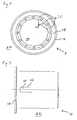
- Fig. 4 shows a plan view of the socket 8 from the in Fig. 2 designated IV direction.
- the viewer's gaze falls directly onto the bottom 48 of this groove 16.
- the latching projections 26 provided on the spring tongues 22 substantially extend on their outside 24 in the circumferential direction over the entire width of the spring tongues 22.
- Fig. 5 that already shows Fig. 1 known locking sleeve 10 in plan view.
- the spring element 40 which secures the securing sleeve 10 against slipping out of the bushing 8, is preferably cut out of the material of the securing sleeve 10 with the aid of a laser cut 46. After the laser cut, the resulting tab is deformed such that the spring element is formed with a directed in the direction of the non-enclosed by the locking sleeve 10 outside space AN relief direction.
- the end piece 2 and the corrugated tube 6 are preferably matched to each other, or it is selected to the respective corrugated tube 6 tail.
- an end piece 2 with a suitable diameter is selected.
- the shape and size of the locking projections 26 of the end piece 2 is adapted to the corrugation of the corrugated tube.
- the extension B of the latching projections 26 in the longitudinal direction L of the bush 8 is chosen so that it is smaller than the distance A (see. Fig. 1 ) of two adjacent shafts 28 of the corrugated tube 6.
- these two size are matched to each other precisely.
- the locking projections 26 on a chamfer which begins at the free ends of the locking projections 26 and the rear portion 20 of the bushing 8 faces. Due to this bevel, the latching projections 26 can easily snap over the individual shafts 28 of the corrugated tube 6 when inserting the bushing 8 into the corrugated hose 6, until finally the end position of the bushing 8 is reached.
Landscapes
- Engineering & Computer Science (AREA)
- General Engineering & Computer Science (AREA)
- Mechanical Engineering (AREA)
- Architecture (AREA)
- Civil Engineering (AREA)
- Structural Engineering (AREA)
- Joints That Cut Off Fluids, And Hose Joints (AREA)
- Quick-Acting Or Multi-Walled Pipe Joints (AREA)
- Rigid Pipes And Flexible Pipes (AREA)
- Infusion, Injection, And Reservoir Apparatuses (AREA)
Description
- Die Erfindung betrifft ein Endstück zum Aufsetzen auf ein Freiende eines Wellschlauches sowie einen Teilesatz mit einem solchen Endstück.
- Wellschläuche bzw. Wellrohre, im Folgenden allgemein als Wellschläuche bezeichnet, werden vielerorts als Schutzrohr für einen eigentlichen Nutzungsträger wie beispielsweise Kabel oder Rohre verwendet. Je nach Einsatzgebiet werden Wellschläuche aus Metall oder Kunststoff eingesetzt. Während für Kabelkanäle in der Gebäudetechnik vornehmlich Wellschläuche aus Kunststoff verwendet werden, werden in der Kernkraftwerkstechnik aufgrund der dort auftretenden Strahlenbelastung vornehmlich Wellschläuche aus Metall eingesetzt. Bei ihrer Montage werden die Wellschläuche auf die jeweils passende Länge zurechtgeschnitten. Beim Abschneiden des Wellschlauches entstehenden an dessen Freienden scharfe Schnittkanten. Diese stellen eine Verletzungsgefahr für den Montagearbeiter dar, und können außerdem dazu führen, dass von dem Wellschlauch aufgenommene Kabel an diesen scharfen Schnittkanten durchgescheuert werden. Neben der Gebäude- und Kernkraftwerkstechnik betrifft dieses Problem auch Roboter und andere Maschinen, bei denen Kabel in einem Wellschlauch einem beweglichen Bauteil zugeführt werden.
- Beide Dokumente des Stands der Technik
US 5160811 A undUS 2004/0178633 A1 offenbaren Endstücke für einen Wellschlauch. - Auf dem Gebiet der Kernkraftwerkstechnik ist außerdem eine Montage unter minimalem Werkzeugeinsatz erstrebenswert, jedes Werkzeug, welches in den Sicherheitsbereich eines Kernkraftwerkes verbracht werden muss, zieht einen erheblichen Aufwand an Sicherungsmaßnahmen nach sich.
- Aufgabe der vorliegenden Erfindung ist es, ein Endstück für einen Wellschlauch sowie einen Teilesatz mit einem solchen Endstück anzugeben, mit dessen Hilfe die von den scharfkantigen Freienden des Wellschlauches ausgehenden Gefahren verringert werden können und welches einfach montierbar ist.
- Die Aufgabe wird gemäß der Erfindung gelöst durch ein Endstück mit den Merkmalen nach Anspruch 1 sowie durch einen Teilesatz mit den Merkmalen nach Anspruch 14 oder 15. Vorteilhafte Ausgestaltungen sind Gegenstand der abhängigen Ansprüche.
- Das erfindungsgemäße Endstück zum Aufsetzen auf ein Freiende eines Wellschlauchs umfasst eine Buchse, mit einem dem Freiende des Wellschlauchs zugewandten vorderen Bereich und einem diesem vorderen Bereich in einer Längsrichtung der Buchse gegenüberliegenden hinteren Bereich, welcher sich im montierten Zustand der Buchse innerhalb des Wellschlauchs befindet. Der vordere Bereich der Buchse besteht aus einem Kragen, welcher das Freiende des Wellschlauchs zumindest teilweise umschließt, radial in Richtung eines von der Buchse nicht umschlossenen Außenraums vorspringt und eine entlang des Umfangs der Buchse verlaufende, sich in Längsrichtung der Buchse öffnende Nut zur zumindest teilweisen Aufnahme des Freiendes des Wellschlauchs bildet. Der in Längsrichtung dem vorderen Bereich gegenüberliegende hintere Bereich der Buchse besteht aus einer Mehrzahl von Federzungen. Diese weisen eine senkrecht zu der Längsrichtung der Buchse orientierte, in Richtung des Außenraums der Buchse gerichtete Entlastungsrichtung auf. Zumindest ein Teil der Federzungen ist mit zumindest einem auf einer dem Außenraum zugewandten Außenseite der jeweiligen Federzunge angeordneten und radial vorspringenden Rastvorsprung zur Realisierung eines in Längsrichtung der Buchse wirksamen Hintergriffs versehen. Das erfindungsgemäße Endstück umfasst außerdem eine von der Buchse aufnehmbare Sicherungshülse, welche sich im montierten Zustand des Endstückes - betrachtet in Längsrichtung - in zumindest einem Teil des hinteren Bereiches der Buchse in einem von der Buchse umschlossenen Innenraum erstreckt. Diese Sicherungshülse begrenzt das Radialspiel der Federzungen in Richtung des Innenraums der Buchse.
- Die Konstruktion des erfindungsgemäßen Endstückes basiert auf den folgenden Überlegungen:
- Zum Schutz der von dem Wellschlauch aufgenommenen Kabel und des den Wellschlauch montierenden Arbeiters wird das scharfkantige Freiende des Wellschlauches von einer Nut einer Buchse abgedeckt. Es wurde erkannt, dass das Wellenprofil eines Wellschlauches eine einfache Möglichkeit bietet, die Buchse in Längsrichtung an dem Wellschlauch zu befestigen. Um eine einfache werkzeuglose Montage zu ermöglichen, wurden Rastvorsprünge, welche in das Wellenprofil des Wellschlauches eingreifen an Federelementen angebracht. Während die Buchse in den Wellschlauch eingeschoben wird, schnappen die federnd gelagerten Rastvorsprünge solange über die einzelnen Wellen des Wellenprofils hinweg, bis die Buchse ihre Endposition erreicht hat. Um einen sicheren Halt des Endstücks an dem Wellschlauch zu gewährleisten, wird eine Sicherungshülse in die Buchse eingebracht, welche verhindert, dass sich der zwischen den Rastvorsprüngen und den Wellen des Wellschlauchs vorhandene Hintergriff durch Zurückschnappen der Federzungen erneut löst.
- Der Vorteil des erfindungsgemäßen Endstückes besteht darin, dass sich dieses einfach und gänzlich ohne zusätzliches Werkzeug montieren lässt. Außerdem ist das erfindungsgemäße Endstück gegen ein versehentliches Abziehen von dem Wellschlauch gesichert, was das Verlegen des Wellschlauches erheblich vereinfacht.
- Gemäß einer ersten Ausführungsform wird die Sicherungshülse passgenau von der Buchse aufgenommen. Dabei begrenzt die Sicherungshülse das Radialspiel der Federzungen auf eine Wegstrecke, die kleiner als die radiale Ausdehnung der Rastvorsprünge in Richtung des Außenraums der Buchse ist. In diesem Zusammenhang wird die radiale Ausdehnung der Rastvorsprünge zwischen einer dem Außenraum zugewanden Außenseite der Buchse und einem Freiende der Rastvorsprünge gemessen. Indem das Radialspiel auf den angegebenen Wert begrenzt wird, ist sichergestellt, dass der Rastvorsprung stets aus der Außenoberfläche der Buchse hervorsteht. Da die Außenoberfläche der Buchse bevorzugt an der Innenfläche des Wellschlauches unmittelbar anliegt, kann sichergestellt werden, dass die Rastvorsprünge stets in die Wellung des Wellschlauchs eingreifen. Das Endstück ist also sicher an dem Wellschlauch gehalten.
- Gemäß einer weiteren Ausführungsform erstreckt sich die Sicherungshülse ausgehend von dem hinteren Bereich der Buchse entlang einer dem Innenraum der Buchse zugewandten Innenseite der Buchse bis in den vorderen Bereich der Buchse. Mit anderen Worten wird die Buchse von der Sicherungshülse praktisch vollständig durchgriffen. Diese Maßnahme trägt zur mechanischen Stabilisierung der Buchse bei, insbesondere wird der hintere Bereich der Buchse, welcher aus einer Vielzahl von Federzungen besteht, vollständig von der im Innenraum der Buchse vorhandenen Sicherungshülse stabilisiert, so dass eine zuverlässige Sicherung der Federzungen gewährleistet ist.
- Um die Zuverlässigkeit des Endstückes weiter zu verbessern, wird, gemäß einer weiteren Ausführungsform, die Sicherungshülse verschiebesicher in der Buchse gehalten. Dabei ist es erstrebenswert, die Sicherungshülse sowohl gegen ein Verschieben in Richtung des hinteren Bereiches als auch gegen ein Verschieben in Richtung des vorderen Bereiches der Buchse zu sichern.
- Ein Verschieben der Sicherungshülse in Richtung des hinteren Bereiches der Buchse wird durch einen an der Buchse vorhandenen Anschlag verhindert. Dieser Anschlag stellt sicher, dass bei der Montage der Sicherungshülse diese nicht versehentlich zu weit in die Buchse hineingedrückt wird. In einem solchen Fall wäre die Sicherung des Endstückes ggf. nicht mehr gewährleistet, das Endstück müsste wieder entfernt und der Wellschlauch eventuell erneut zugeschnitten werden. Ein solcher Anschlag verbessert also die Handhabung des Endstückes.
- Gemäß einer weiteren Ausführungsform wird der Anschlag zwischen einem sich am hinteren Ende der Buchse in radialer Richtung in Richtung des Innenraumes der Buchse erstreckenden Vorsprung und einem dem hinteren Ende der Buchse zugewandten Freiende der Sicherungshülse hergestellt. Vorteilhaft werden mit einem solchen Anschlag neben der Sicherungshülse gleichzeitig die Federzungen gesichert.
- Das vorgeschlagene Endstück dient dazu, eine Beschädigung der in dem Wellschlauch geführten Kabel zu verhindern. Somit sollte das Endstück selbst keine neuen Gefahrenquellen für die geführten Kabel mit sich bringen. Aus diesem Grund schließen, gemäß einer Weiterbildung, der sich in Richtung des Innenraums der Buchse erstreckende Vorsprung und die Innenseite der Sicherungshülse formschlüssig ab. Eine dem Innenraum zugewandte scharfe Kante kann somit wirksam vermieden werden, wodurch die Gefahr für Beschädigungen der im Inneren des Wellschlauches geführten Kabel wesentlich verringert werden kann.
- Alternativ oder zusätzlich zu den zuvor genannten Maßnahmen wird die Sicherungshülse gegen ein Verschieben in Richtung des hinteren Bereiches der Buchse mit Hilfe eines Anschlages gesichert, welcher zwischen einer an einer vorderen Stirnseite des Kragens vorhandenen, radial umlaufenden Freidrehung und einem an dem vorderen Freiende der Sicherungshülse vorhandenen, radial in Richtung des Außenraums vorspringenden Flansch hergestellt ist. Vorteilhaft kann der Monteur leicht feststellen, ob der in Rede stehende Anschlag vorliegt oder nicht. Somit kann der akkurate Sitz der Sicherungshülse durch einfache Sichtkontrolle festgestellt werden. Gemäß einer Weiterbildung schließen die Stirnseite des Flansches und die Stirnseite des Kragens bündig ab. Die Verletzungsgefahr für die aus dem Endstück ausmündenden Kabel sowie für einen Monteur, welcher nach Aufsetzen des Endstückes auf den Wellschlauch mit diesem hantiert, kann deutlich verringert werden.
- Um einen sicheren Halt des Endstückes auf dem Freiende des Wellschlauches zu gewährleisten, soll, gemäß einer weiteren Ausführungsform, nicht nur ein Hineinrutschen der Sicherungshülse in die Buchse, sondern auch deren Herausrutschen aus der Sicherungshülse verhindert werden. Aus diesem Grund ist die Sicherungshülse gegen eine Verschiebung in Richtung des vorderen Bereiches der Buchse durch einen Hintergriff zumindest eines an der Sicherungshülse vorhandenen Federelementes, welches in eine an der Buchse vorhandene Nut eingreift, gesichert. Eine solche Konstruktion erlaubt es, die Sicherungshülse nach der Art einer "Klick-Verbindung" mit der Buchse zu verbinden. Gemäß einer Weiterbildung weist das an der Sicherungsbuchse vorhandene Federelement eine in Richtung des Außenraums gerichtete Entlastungsrichtung auf. Die in der Buchse vorhandene Nut ist in diesem Fall in Richtung des Innenraums geöffnet. Bevorzugt ragt das Federelement nicht in den Innenraum der Sicherungshülse hinein, so dass auch dieses für die im Innenraum geführten Kabel kein Beschädigungsrisiko darstellt. Um eine schnelle Montage des Endstückes auf dem Freiende des Wellschlauches zu ermöglichen ist, gemäß einer weiteren Ausführungsform, die Nut radial umlaufend in die Buchse eingelassen. Somit ist die Verbindung zwischen der Buchse und der Sicherungshülse drehinvariant; dies erleichtert die Montage der Sicherungshülse erheblich.
- Gemäß einer weiteren Ausführungsform weisen die Rastvorsprünge eine Abschrägung auf, welche beginnend an ihren Freienden in Richtung des hinteren Bereiches der Buchse verläuft. Beim Einschieben der Buchse in das Ende des Wellschlauches springen die Rastvorsprünge von einer Welle des Wellschlauches zur nächsten, solange, bis die Endposition des Endstückes erreicht ist. Mit Hilfe der vorgesehenen Abschrägungen wird das Überspringen der Wellen beim Hineinschieben des Endstückes in den Wellschlauch erleichtert; ein Herausziehen desselben jedoch erschwert. Somit ist bereits ohne, dass die Sicherungshülse in die Buchse eingeschoben wird, erstere gegenüber versehentlichem Herausziehen gesichert.
- Der erfindungsgemäße Teilesatz besteht aus einem Wellschlauch und einem oben erläuterten Endstück. Die Ausdehnung der radial vorspringenden Rastvorsprünge dieses Endstückes ist in Längsrichtung desselben kleiner als der zwischen benachbarten Wellen des Wellschlauches - gemessen auf der Innenseite des Wellschlauches - vorhandene Freiraum. Mit anderen Worten ist die Ausdehnung der Rastvorsprünge in Längsrichtung des Endstückes an die Innenabstände der Wellen des Wellschlauches angepasst. Wellschlauch und Endstück sind also aufeinander abgestimmt.
- Dies gilt für einen alternativen Teilesatz, bei dem die Rastvorsprünge passgenau zu dem vorgenannten Freiraum bemessen sind.
- Gemäß einer Ausführungsform weist der Kragen des Endstückes einen radial umlaufenden, sich in Richtung des hinteren Bereiches der Buchse erstreckenden Außenmantel auf, welcher die Nut in Richtung des Außenraums begrenzt. Dieser Außenmantel ist nun derart dimensioniert, dass der Abstand zwischen einem Boden der Nut und einem Freiende des Außenmantels größer ist als der Abstand benachbarter Wellen des Wellschlauches. Eine solche Konstruktion hat den Effekt, dass das Freiende des Wellschlauches stets von der Nut des Kragens aufgenommen ist.
- Im Folgenden wird die Erfindung unter Bezugnahme auf die Figuren der Zeichnungen näher erläutert. Sich entsprechende Teile sind dabei mit den gleichen Bezugszeichen versehen.
- Fig. 1
- zeigt einen Längsschnitt durch einen Wellschlauch sowie ein jeweils halbseitig in einem Längsschnitt bzw. in Draufsicht dargestelltes Endstück,
- Fig. 2
- zeigt eine halbseitig in einem Längsschnitt bzw. in Draufsicht dargestellte Buchse,
- Fig. 3
- zeigt einen Ausschnitt der
Fig. 2 , - Fig. 4
- zeigt die aus
Fig. 2 bekannte Buchse in einer Aufsicht aus der inFig. 2 mit IV bezeichneten Richtung und - Fig. 5
- zeigt eine Sicherungshülse in Draufsicht.
-
Fig. 1 zeigt ein Endstück 2, welches auf ein Freiende 4 eines Wellschlauches 6 aufgesetzt ist. Das Endstück 2 ist bis zu seiner Mittenachse M, welche sich in einer Längsrichtung L des Endstückes 2 erstreckt, auf der inFig. 1 unten gezeigten Hälfte geschnitten und in der oberen Hälfte in Draufsicht dargestellt. Das Endstück 2 besteht aus einer Buchse 8, welche eine Sicherungshülse 10 passgenau aufnimmt. In einem vorderen Bereich 12 der Buchse 8 besteht diese aus einem Kragen 14, welcher eine Nut 16 zur Aufnahme des Freiendes 4 des Wellschlauches 6 ausbildet. In Richtung eines Außenraumes AN ist die Nut 16 durch einen Außenmantel 18 begrenzt. In einem dem vorderen Bereich 12 in Längsrichtung L der Buchse 8 entgegengesetzten hinteren Bereich 20, der sich im montierten Zustand des Endstückes 2 innerhalb des Wellschlauches 6 befindet, besteht die Buchse 8 aus einer Vielzahl von Federzungen 22. Diese Federzungen 22 weisen eine in Richtung des Außenraumes AN der Buchse 8 gerichtete Entlastungsrichtung auf. Auf ihrer dem Außenraum AN zugewandten Außenseite 24 befinden sich radial vorspringende Rastvorsprünge 26. Mit Hilfe dieser Rastvorsprünge 26 wird ein in Längsrichtung L wirksamer Hintergriff zwischen einer der Wellen 28 des Wellschlauches 6 und der Buchse 8 hergestellt. Die Buchse 8 umschließt einen Innenraum IN, in diesem erstreckt sich im Wesentlichen über die gesamte Länge der Buchse 8 die Sicherungshülse 10. Diese dient dazu, das Radialspiel der Federzungen 22 derart zu begrenzen, dass das Endstück 2 sicher in dem Wellschlauch 6 gehalten ist. Zu diesem Zweck ist die Sicherungshülse 10 passgenau in die Buchse 8 eingepasst. Sie begrenzt das Radialspiel der Federzungen 22 in Richtung des Innenraumes IN auf eine Wegstrecke, die kleiner ist als die radiale Ausdehnung BR (vgl.Fig. 2 ) der Rastvorsprünge 26 in Richtung des Außenraumes AN der Buchse 8. Die radiale Ausdehnung BR der Rastvorsprünge 26 wird ausgehend von einer dem Außenraum AN zugewandten Außenseite 24 der Federzungen 22 und einem Freiende der entsprechenden Federzunge 26 gemessen. - Die Sicherungshülse 10 ist verschiebesicher in der Buchse 8 gehalten. Grundsätzlich wäre es möglich die Verschiebesicherheit durch einen reibschlüssigen Sitz der Sicherungshülse 10 in der Buchse 8 zu gewährleisten. Im vorliegenden Ausführungsbeispiel wird die Sicherungshülse 10 jedoch durch einen zwischen der Buchse 8 und der Sicherungshülse 10 vorhandenen Anschlag gegen Verschiebung in Richtung des hinteren Bereiches 20 der Buchse 8 gesichert. Dieser Anschlag befindet sich zwischen einem sich radial in Richtung des Innenraumes IN der Buchse 8 erstreckenden Vorsprung 30 und einem im hinteren Bereich 20 der Buchse 8 anliegenden Freiende der Sicherungshülse 10. Um für die im Innenraum IN des Endstücks 2 sowie die innerhalb des Wellschlauches 6 geführten Kabel jegliche Verletzungsgefahr auszuschließen, schließt die Innenseite 32 der Sicherungshülse 10 mit dem Vorsprung 30 formschlüssig ab.
- Ein weiterer Anschlag besteht zwischen einer in die vordere Stirnseite 34 des Kragens 14 eingelassenen Freidrehung 36 und einem radial umlaufenden, in Richtung des Außenraumes AN vorspringenden Flansch 38 der Sicherungshülse 10. Um auch in diesem Bereich des Endstücks scharfe Kanten nach Möglichkeit vollständig zu vermeiden, schließen die Stirnseite 34 des Kragens 14 und die Stirnseite des Flansches 38 bündig ab.
- Um neben einem Hineinrutschen der Sicherungshülse 10 in den Wellschlauch 6 auch eine Herausrutschen der Sicherungshülse 10 aus der Buchse 8 zu verhindern, ist die Sicherungshülse 10 mit Hilfe eines Federelementes 40 gesichert. Dieses Federelement 40 greift in eine in die Innenseite der Buchse 8 eingelassene Sicherungsnut 42, welche in Richtung des Innenraumes IN geöffnet ist. Das Federelement 40, welches einteilig an die Sicherungshülse 10 angeformt ist, weist eine in Richtung des Außenraumes AN gerichtete Entlastungsrichtung auf. Die Sicherungsnut 42 erstreckt sich radial umlaufend in der Buchse 8, und sichert so einen drehinvarianten Sitz der Sicherungshülse 10 in der Buchse 8.
-
Fig. 2 zeigt die bereits ausFig. 1 bekannten Buchse 8 allein, wobei im unteren Teil der Darstellung diese in einem Längsschnitt und im oberen Teil in Draufsicht dargestellt ist. Die Federzungen 22 sind einstückig an die Buchse 8 angeformt, um deren Flexibilität in Radialrichtung zu gewährleisten, befindet sich im Bereich des Überganges zwischen dem eigentlichen Körper der jeweiligen Federzunge 22 und der Buchse 8 eine Verjüngung 44. Ebenfalls gut sichtbar ist die radial auf der Innenseite der Buchse 8 umlaufende Sicherungsnut 42, in welche das Federelement 40 der Sicherungshülse 10 eingreift. -
Fig. 3 zeigt eine vergrößerte Ansicht des inFig. 2 entsprechend markierten Ausschnitts. Deutlich sichtbar ist die zur Aufnahme des Freiendes 4 des Wellschlauches 6 vorgesehene Nut 16, sowie die die Elastizität der Federzungen 22 gewährleistende Verjüngung 44. Der radial umlaufende Außenmantel 18 des Kragens 14 begrenzt die Nut 16 in Radialrichtung. Die Höhe 52 des Außenmantels 18 in Längsrichtung L, welche zwischen einem Boden 48 der Nut 16 und einem Freiende 50 des Außenmantels 18 gemessen wird, ist größer als der Abstand 54 (vgl.Fig. 1 ) benachbarter Wellen 28 des Wellschlauchs 6 gewählt. Diese Dimensionierung des Außenmantels 18 sorgt dafür, dass das Freiende 4 des Wellschlauches 6 stets von der Nut 16 der Buchse 8 aufgenommen wird. -
Fig. 4 zeigt eine Draufsicht der Buchse 8 aus der inFig. 2 mit IV bezeichneten Richtung. Deutlich sichtbar ist die in die nunmehr senkrecht auf der Papierebene weisende Längsrichtung L geöffnete Nut 16. Der Blick des Betrachters fällt unmittelbar auf den Boden 48 dieser Nut 16. Die an den Federzungen 22 vorhandenen Rastvorsprünge 26 erstrecken sich auf deren Außenseite 24 in Umfangsrichtung im Wesentlichen über die komplette Breite der Federzungen 22. -
Fig. 5 zeigt die bereits ausFig. 1 bekannte Sicherungshülse 10 in Draufsicht. Das Federelement 40, welches die Sicherungshülse 10 gegen ein Herausrutschen aus der Buchse 8 sichert, wird vorzugsweise mit Hilfe eines Laserschnittes 46 aus dem Material der Sicherungshülse 10 herausgeschnitten. Nach erfolgtem Laserschnitt wird die entstandene Lasche derart verformt, dass das Federelement mit einer in Richtung des von der Sicherungshülse 10 nicht umschlossenen Außenraums AN gerichteten Entlastungsrichtung entsteht. - Das Endstück 2 und der Wellschlauch 6 werden vorzugsweise aufeinander abgestimmt, bzw. es wird ein zu dem jeweiligen Wellschlauch 6 passendes Endstück ausgewählt. Beispielsweise wird ein Endstück 2 mit passendem Durchmesser ausgewählt. Außerdem wird die Form und Größe der Rastvorsprünge 26 des Endstücks 2 an die Wellung des Wellschlauchs angepasst. So ist die Ausdehnung B der Rastvorsprünge 26 in Längsrichtung L der Buchse 8 so gewählt, dass diese kleiner ist, als der Abstand A (vgl.
Fig. 1 ) zweier benachbarter Wellen 28 des Wellschlauchs 6. Vorzugsweise werden diese beiden Größe passgenau aufeinander abgestimmt. Um außerdem die Montage der Buchse 8 zu erleichtern, weisen die Rastvorsprünge 26 eine Abschrägung auf, welche an den Freienden der Rastvorsprünge 26 beginnt und dem hinteren Bereich 20 der Buchse 8 zugewandt ist. Aufgrund dieser Abschrägung können beim Einstecken der Buchse 8 in den Wellschlauch 6 die Rastvorsprünge 26 leicht über die einzelnen Wellen 28 des Wellschlauches 6 schnappen, bis schließlich die Endposition der Buchse 8 erreicht ist.
Claims (16)
- Endstück (2) zum Aufsetzen auf ein Freiende (4) eines Wellschlauches (6), umfassend:a) eine Buchse (8), mit einem dem Freiende (4) des Wellschlauches (6) zugewandten vorderen Bereich (12) und einem diesem vorderen Bereich (12) in einer Längsrichtung (L) der Buchse (8) gegenüberliegenden hinteren Bereich (20), welcher sich im montierten Zustand der Buchse (8) innerhalb des Wellschlauches (6) befindet, wobeia1) der vordere Bereich (12) der Buchse (8) aus einem Kragen (14) besteht, welcher das Freiende (4) des Wellschlauches (6) zumindest teilweise umschließt, radial in Richtung eines von der Buchse (8) nicht umschlossenen Außenraumes (AN) vorspringt und eine entlang des Umfangs der Buchse (8) verlaufende, sich in Längsrichtung (L) der Buchse (8) öffnende Nut (16) zur zumindest teilweisen Aufnahme des Freiendes (4) des Wellschlauches (6) bildet, und wobeia2) der hintere Bereich (20) der Buchse (8) aus einer Mehrzahl von Federzungen (22) besteht, welche eine senkrecht zu der Längsrichtung (L) der Buchse (8) orientierte, in Richtung des Außenraumes (AN) der Buchse (8) gerichtete Entlastungsrichtung aufweisen, wobei zumindest ein Teil der Federzungen (22) an ihrer dem Außenraum (AN) zugewandten Außenseite (24) jeweils zumindest einen radial vorspringenden Rastvorsprung (26) zur Realisierung eines in Längsrichtung (L) der Buchse (8) wirksamen Hintergriffs aufweisen,b) eine von der Buchse (8) aufnehmbare Sicherungshülse (10), welche sich im montierten Zustand des Endstückes (2) in zumindest einem Teil des hinteren Bereichs (20) in Längsrichtung (L) der Buchse (8) in einem von der Buchse (8) umschlossenen Innenraum (IN) erstreckt und das Radialspiel der Federzungen (22) in Richtung des Innenraums (IN) der Buchse (8) begrenzt.
- Endstück (2) nach Anspruch 1, bei dem die Sicherungshülse (10) passgenau von der Buchse (8) aufgenommen wird und das Radialspiel der Federzungen (22) in Richtung des Innenraums (IN) der Buchse (8) auf eine Wegstrecke begrenzt, die kleiner als die radiale Ausdehnung (BR) der Rastvorsprünge (26) in Richtung des Außenraums (AN) der Buchse (8) ist.
- Endstück (2) nach Anspruch 1 oder 2, bei dem sich die Sicherungshülse (8) ausgehend von dem hinteren Bereich (20) der Buchse (8) entlang einer dem Innenraum (IN) der Buchse (8) zugewandten Innenseite bis in den vorderen Bereich (12) der Buchse (8) erstreckt.
- Endstück (2) nach einem der vorstehenden Ansprüche, bei dem die Sicherungshülse (10) verschiebesicher in der Buchse (8) gehalten ist.
- Endstück (2) nach Anspruch 4, bei dem die Sicherungshülse (10) gegen eine Verschiebung in Richtung des hinteren Bereichs (20) der Buchse (8) durch einen an der Buchse (8) vorhandenen Anschlag gesichert ist.
- Endstück (2) nach Anspruch 5, bei dem der Anschlag zwischen einem an dem hinteren Ende (20) der Buchse (8) vorhandenen, sich radial in Richtung des Innenraums (IN) der Buchse (8) erstreckenden Vorsprung (30) und einem dem hinteren Ende (20) der Buchse (8) zugewandten Freiende der Sicherungshülse (10) hergestellt ist.
- Endstück (2) nach Anspruch 6, bei dem der sich in Richtung des Innenraums (IN) erstreckende Vorsprung (30) und eine Innenseite (32) der Sicherungshülse (10) formschlüssig abschließen.
- Endstück (2) nach einem der Ansprüche 5 bis 7, bei dem der Anschlag zwischen einer an einer vorderen Stirnseite (34) des Kragens (14) vorhandenen, radial umlaufenden Freidrehung (36) und einem an dem vorderen Freiende der Sicherungshülse (10) vorhandenen, radial in Richtung des Außenraums (AN) vorspringenden Flansch (38) hergestellt ist.
- Endstück (2) nach Anspruch 8, bei dem die Stirnseite des Flansches und die Stirnseite (34) des Kragens (14) bündig abschließen.
- Endstück (2) nach einem der Ansprüche 4 bis 9, bei dem die Sicherungshülse (10) gegen eine Verschiebung in Richtung des vorderen Bereichs (12) der Buchse (8) durch Hintergriff zumindest eines an der Sicherungshülse (10) vorhandenen Federelements (40) in einer an der Buchse (8) vorhandene Sicherungsnut (42) gesichert ist.
- Endstück (2) nach Anspruch 10, bei dem das an der Sicherungsbuchse (10) vorhandene Federelement (40) eine in Richtung des Außenraums (AN) gerichtete Entlastungsrichtung aufweist und die in der Buchse (8) vorhandene Sicherungsnut (42) in Richtung ihres Innenraums (IN) geöffnet ist.
- Endstück (2) nach Anspruch 11, bei dem sich die Sicherungsnut (42) radial umlaufend erstreckt, und in die Buchse (8) eingelassen ist.
- Endstück (2) nach einem der vorstehenden Ansprüche, bei dem zumindest einer der Rastvorsprünge (26) eine Abschrägung aufweist, welche an dem Freiende des Rastvorsprungs (26) beginnend in Richtung des hinteren Bereichs (20) der Buchse (8) verläuft.
- Teilesatz bestehend aus einem Wellschlauch (6) und einem Endstück (2) nach einem der Ansprüche 1 bis 13, wobei die Ausdehnung (B) der radial vorspringenden Rastvorsprünge (26) in Längsrichtung (L) kleiner als der zwischen benachbarten Wellen (28) des Wellschlauches (6) - gemessen auf der Innenseite (IN) des Wellschlauches (6) - vorhandene Freiraum (A) ist.
- Teilesatz bestehend aus einem Wellschlauch (6) und einem Endstück (2) nach einem der Ansprüche 1 bis 13, bei dem die Rastvorsprünge (26) passgenau zu dem Freiraum (A) bemessen sind.
- Teilesatz nach Anspruch 14 oder 15, bei dem der Kragen (14) des Endstücks (2) einen radial umlaufenden, sich in Richtung des hinteren Bereichs der Buchse (8) erstreckenden Außenmantel (18), welcher die Nut (16) in Richtung des Außenraums (AN) begrenzt, aufweist, wobei dieser Außenmantel (18) derart dimensioniert ist, dass der Abstand (52) zwischen einem Boden (48) der Nut (16) und einem Freiende (50) des Außenmantels (18) größer ist als ein Abstand (54) benachbarter Wellen (28) des Wellschlauches (6).
Applications Claiming Priority (2)
| Application Number | Priority Date | Filing Date | Title |
|---|---|---|---|
| DE102009027843A DE102009027843B3 (de) | 2009-07-20 | 2009-07-20 | Endstück für einen Wellschlauch und Teilesatz mit einem solchen Endstück |
| PCT/EP2010/060005 WO2011009753A1 (de) | 2009-07-20 | 2010-07-13 | Endstück für einen wellschlauch und teilesatz mit einem solchen endstück |
Publications (2)
| Publication Number | Publication Date |
|---|---|
| EP2391845A1 EP2391845A1 (de) | 2011-12-07 |
| EP2391845B1 true EP2391845B1 (de) | 2015-03-04 |
Family
ID=42827455
Family Applications (1)
| Application Number | Title | Priority Date | Filing Date |
|---|---|---|---|
| EP10742779.1A Not-in-force EP2391845B1 (de) | 2009-07-20 | 2010-07-13 | Endstück für einen wellschlauch und teilesatz mit einem solchen endstück |
Country Status (8)
| Country | Link |
|---|---|
| US (1) | US8282137B2 (de) |
| EP (1) | EP2391845B1 (de) |
| BR (1) | BRPI1005400A8 (de) |
| CA (1) | CA2749651C (de) |
| DE (1) | DE102009027843B3 (de) |
| ES (1) | ES2535649T3 (de) |
| RU (1) | RU2462645C1 (de) |
| WO (1) | WO2011009753A1 (de) |
Families Citing this family (6)
| Publication number | Priority date | Publication date | Assignee | Title |
|---|---|---|---|---|
| ITMI20110882A1 (it) * | 2011-05-18 | 2012-11-19 | Miflex 2 S R L | Dispositivo di raccordo a struttura perfezionata per connettere tubi per il passaggio di fluidi in pressione |
| JP6057176B2 (ja) | 2013-08-09 | 2017-01-11 | 住友電装株式会社 | ホルダー |
| DE102013112999A1 (de) * | 2013-11-25 | 2015-05-28 | Witzenmann Gmbh | Verbindung mit einem zumindest abschnittweise profilierten Schlauchleitungselement |
| DE102015120508A1 (de) * | 2015-11-26 | 2017-06-01 | Norma Germany Gmbh | Verbindungsanordnung für ein Kühlmittelsystem und Verfahren zur Herstellung einer Verbindungsanordnung |
| MX2021013280A (es) | 2019-05-03 | 2022-04-06 | Hydro Extrusion Usa Llc | Conducto electrico extruido acanalado. |
| JP2022106329A (ja) * | 2021-01-07 | 2022-07-20 | 矢崎総業株式会社 | コルゲートチューブ保護部材 |
Citations (1)
| Publication number | Priority date | Publication date | Assignee | Title |
|---|---|---|---|---|
| US5160811A (en) * | 1990-04-27 | 1992-11-03 | Tyton Corporation | Duct transition converter and flexible connectors including same |
Family Cites Families (9)
| Publication number | Priority date | Publication date | Assignee | Title |
|---|---|---|---|---|
| US589216A (en) * | 1897-08-31 | Hose-fitting | ||
| US3672708A (en) * | 1970-06-29 | 1972-06-27 | United States Steel Corp | Coupling device |
| US4247136A (en) * | 1978-12-22 | 1981-01-27 | Hancor, Inc. | Internal coupling structure and joint for pipe or tubing |
| CA1243089A (en) * | 1984-05-18 | 1988-10-11 | William Nattel | Conduit connector |
| US5799989A (en) * | 1996-08-08 | 1998-09-01 | Omega-Flex, Inc. | Corrugated tubing fitting |
| JP3225311B2 (ja) * | 1997-07-15 | 2001-11-05 | 東拓工業株式会社 | 環状凹凸波形管用ベルマウス |
| DE10104449C2 (de) * | 2001-02-01 | 2003-11-13 | Eaton Fluid Power Gmbh | Wellrohrschlaucharmatur |
| DE10310938A1 (de) * | 2003-03-13 | 2004-09-23 | Brugg Rohr Ag, Holding | Verfahren zur Herstellung einer Verbindung zwischen einem Wellrohr und einem Anschlußstück |
| US7290804B2 (en) * | 2003-03-13 | 2007-11-06 | Witzenmann Gmbh | Plug connection between a corrugated hose and an unprofiled pipe |
-
2009
- 2009-07-20 DE DE102009027843A patent/DE102009027843B3/de not_active Expired - Fee Related
-
2010
- 2010-07-13 BR BRPI1005400A patent/BRPI1005400A8/pt not_active Application Discontinuation
- 2010-07-13 EP EP10742779.1A patent/EP2391845B1/de not_active Not-in-force
- 2010-07-13 WO PCT/EP2010/060005 patent/WO2011009753A1/de not_active Ceased
- 2010-07-13 ES ES10742779.1T patent/ES2535649T3/es active Active
- 2010-07-13 CA CA2749651A patent/CA2749651C/en not_active Expired - Fee Related
- 2010-07-13 RU RU2011122811/06A patent/RU2462645C1/ru not_active IP Right Cessation
-
2011
- 2011-05-09 US US13/103,316 patent/US8282137B2/en not_active Expired - Fee Related
Patent Citations (1)
| Publication number | Priority date | Publication date | Assignee | Title |
|---|---|---|---|---|
| US5160811A (en) * | 1990-04-27 | 1992-11-03 | Tyton Corporation | Duct transition converter and flexible connectors including same |
Also Published As
| Publication number | Publication date |
|---|---|
| CA2749651C (en) | 2013-12-10 |
| WO2011009753A1 (de) | 2011-01-27 |
| DE102009027843B3 (de) | 2010-11-11 |
| EP2391845A1 (de) | 2011-12-07 |
| BRPI1005400A8 (pt) | 2016-10-04 |
| RU2462645C1 (ru) | 2012-09-27 |
| BRPI1005400A2 (pt) | 2016-03-08 |
| CA2749651A1 (en) | 2011-01-27 |
| US8282137B2 (en) | 2012-10-09 |
| US20110227333A1 (en) | 2011-09-22 |
| ES2535649T3 (es) | 2015-05-13 |
Similar Documents
| Publication | Publication Date | Title |
|---|---|---|
| DE3640226C2 (de) | ||
| DE69916518T2 (de) | Pipe flange sealing ring | |
| DE102009027843B3 (de) | Endstück für einen Wellschlauch und Teilesatz mit einem solchen Endstück | |
| EP2218873A1 (de) | Rotorabschnitt für einen Rotor einer Turbomaschine, Laufschaufel für eine Turbomaschine und Blockierelement | |
| EP3152809A2 (de) | Elektrisches gerät | |
| EP1648067B1 (de) | Kühl- und/oder Gefriergerät mit Dichtelement | |
| EP2587106A1 (de) | Brandschutzmanschette | |
| DE102004057192B4 (de) | Bindebandbefestigungsanordnung | |
| DE3439655A1 (de) | Steckerteil mit schutzgehaeuse fuer das kabelende | |
| DE102017100490A1 (de) | Rohrmontagekomponente und Anordnung mit einem Rohrende | |
| DE69304088T2 (de) | Abgeschirmte Verbindung vorbereitet für die Montage eines Verbinders | |
| EP3726267A1 (de) | Einzelrohrabdichtung und kunststoffrohr | |
| DE68907211T2 (de) | Markierungsanordnung. | |
| EP3514287B1 (de) | Rahmen für einen kabelschacht | |
| DE19905809A1 (de) | Anschlußverbindung und Anschlußelement für ringgewellte Schlauchleitungen | |
| DE3619299C2 (de) | ||
| DE9320431U1 (de) | Ringwellschlauch oder -balg aus Metall mit einem Anschlußelement | |
| DE4137421C2 (de) | Elektrische Hohlwanddose, wie Schalterdose, Abzweigdose od. dgl. | |
| EP3293843B1 (de) | Dichtelement für kabelschutzrohr | |
| EP3614030B1 (de) | Leitungselement mit integriertem halter für fixierungsmittel | |
| DE202010003282U1 (de) | Vorrichtung zum Verbinden eines Metallrohres mit einem Kunststoffrohr | |
| EP0290955A2 (de) | Einrichtung zum Abdichten von miteinander verbundenen Leitern von Kabeln | |
| DE102015116961B4 (de) | Rohrkappensatz und Anordnung mit einem solchen | |
| EP1717922B1 (de) | Gehäuse mit einer Durchführung für einen elektrischen Leiter | |
| DE8709907U1 (de) | Vorrichtung zum Einziehen von Kabeln in Kabelschutzrohre |
Legal Events
| Date | Code | Title | Description |
|---|---|---|---|
| PUAI | Public reference made under article 153(3) epc to a published international application that has entered the european phase |
Free format text: ORIGINAL CODE: 0009012 |
|
| 17P | Request for examination filed |
Effective date: 20110726 |
|
| AK | Designated contracting states |
Kind code of ref document: A1 Designated state(s): AL AT BE BG CH CY CZ DE DK EE ES FI FR GB GR HR HU IE IS IT LI LT LU LV MC MK MT NL NO PL PT RO SE SI SK SM TR |
|
| DAX | Request for extension of the european patent (deleted) | ||
| RAP1 | Party data changed (applicant data changed or rights of an application transferred) |
Owner name: AREVA GMBH |
|
| REG | Reference to a national code |
Ref country code: DE Ref legal event code: R079 Ref document number: 502010009067 Country of ref document: DE Free format text: PREVIOUS MAIN CLASS: F16L0025000000 Ipc: H02G0003040000 |
|
| RIC1 | Information provided on ipc code assigned before grant |
Ipc: F16L 25/00 20060101ALI20140711BHEP Ipc: F16L 33/30 20060101ALI20140711BHEP Ipc: H02G 3/04 20060101AFI20140711BHEP Ipc: F16L 33/26 20060101ALI20140711BHEP Ipc: H02G 3/06 20060101ALI20140711BHEP |
|
| GRAP | Despatch of communication of intention to grant a patent |
Free format text: ORIGINAL CODE: EPIDOSNIGR1 |
|
| INTG | Intention to grant announced |
Effective date: 20140924 |
|
| GRAS | Grant fee paid |
Free format text: ORIGINAL CODE: EPIDOSNIGR3 |
|
| GRAA | (expected) grant |
Free format text: ORIGINAL CODE: 0009210 |
|
| AK | Designated contracting states |
Kind code of ref document: B1 Designated state(s): AL AT BE BG CH CY CZ DE DK EE ES FI FR GB GR HR HU IE IS IT LI LT LU LV MC MK MT NL NO PL PT RO SE SI SK SM TR |
|
| REG | Reference to a national code |
Ref country code: GB Ref legal event code: FG4D Free format text: NOT ENGLISH |
|
| REG | Reference to a national code |
Ref country code: CH Ref legal event code: EP |
|
| REG | Reference to a national code |
Ref country code: IE Ref legal event code: FG4D Free format text: LANGUAGE OF EP DOCUMENT: GERMAN |
|
| REG | Reference to a national code |
Ref country code: AT Ref legal event code: REF Ref document number: 714595 Country of ref document: AT Kind code of ref document: T Effective date: 20150415 Ref country code: CH Ref legal event code: NV Representative=s name: E. BLUM AND CO. AG PATENT- UND MARKENANWAELTE , CH |
|
| REG | Reference to a national code |
Ref country code: DE Ref legal event code: R096 Ref document number: 502010009067 Country of ref document: DE Effective date: 20150416 |
|
| REG | Reference to a national code |
Ref country code: ES Ref legal event code: FG2A Ref document number: 2535649 Country of ref document: ES Kind code of ref document: T3 Effective date: 20150513 |
|
| REG | Reference to a national code |
Ref country code: SE Ref legal event code: TRGR |
|
| REG | Reference to a national code |
Ref country code: NL Ref legal event code: VDEP Effective date: 20150304 |
|
| PG25 | Lapsed in a contracting state [announced via postgrant information from national office to epo] |
Ref country code: HR Free format text: LAPSE BECAUSE OF FAILURE TO SUBMIT A TRANSLATION OF THE DESCRIPTION OR TO PAY THE FEE WITHIN THE PRESCRIBED TIME-LIMIT Effective date: 20150304 Ref country code: NO Free format text: LAPSE BECAUSE OF FAILURE TO SUBMIT A TRANSLATION OF THE DESCRIPTION OR TO PAY THE FEE WITHIN THE PRESCRIBED TIME-LIMIT Effective date: 20150604 Ref country code: LT Free format text: LAPSE BECAUSE OF FAILURE TO SUBMIT A TRANSLATION OF THE DESCRIPTION OR TO PAY THE FEE WITHIN THE PRESCRIBED TIME-LIMIT Effective date: 20150304 |
|
| REG | Reference to a national code |
Ref country code: LT Ref legal event code: MG4D |
|
| PG25 | Lapsed in a contracting state [announced via postgrant information from national office to epo] |
Ref country code: GR Free format text: LAPSE BECAUSE OF FAILURE TO SUBMIT A TRANSLATION OF THE DESCRIPTION OR TO PAY THE FEE WITHIN THE PRESCRIBED TIME-LIMIT Effective date: 20150605 Ref country code: LV Free format text: LAPSE BECAUSE OF FAILURE TO SUBMIT A TRANSLATION OF THE DESCRIPTION OR TO PAY THE FEE WITHIN THE PRESCRIBED TIME-LIMIT Effective date: 20150304 |
|
| PG25 | Lapsed in a contracting state [announced via postgrant information from national office to epo] |
Ref country code: NL Free format text: LAPSE BECAUSE OF FAILURE TO SUBMIT A TRANSLATION OF THE DESCRIPTION OR TO PAY THE FEE WITHIN THE PRESCRIBED TIME-LIMIT Effective date: 20150304 |
|
| PG25 | Lapsed in a contracting state [announced via postgrant information from national office to epo] |
Ref country code: RO Free format text: LAPSE BECAUSE OF FAILURE TO SUBMIT A TRANSLATION OF THE DESCRIPTION OR TO PAY THE FEE WITHIN THE PRESCRIBED TIME-LIMIT Effective date: 20150304 Ref country code: PT Free format text: LAPSE BECAUSE OF FAILURE TO SUBMIT A TRANSLATION OF THE DESCRIPTION OR TO PAY THE FEE WITHIN THE PRESCRIBED TIME-LIMIT Effective date: 20150706 Ref country code: EE Free format text: LAPSE BECAUSE OF FAILURE TO SUBMIT A TRANSLATION OF THE DESCRIPTION OR TO PAY THE FEE WITHIN THE PRESCRIBED TIME-LIMIT Effective date: 20150304 Ref country code: SK Free format text: LAPSE BECAUSE OF FAILURE TO SUBMIT A TRANSLATION OF THE DESCRIPTION OR TO PAY THE FEE WITHIN THE PRESCRIBED TIME-LIMIT Effective date: 20150304 |
|
| PG25 | Lapsed in a contracting state [announced via postgrant information from national office to epo] |
Ref country code: IS Free format text: LAPSE BECAUSE OF FAILURE TO SUBMIT A TRANSLATION OF THE DESCRIPTION OR TO PAY THE FEE WITHIN THE PRESCRIBED TIME-LIMIT Effective date: 20150704 Ref country code: PL Free format text: LAPSE BECAUSE OF FAILURE TO SUBMIT A TRANSLATION OF THE DESCRIPTION OR TO PAY THE FEE WITHIN THE PRESCRIBED TIME-LIMIT Effective date: 20150304 |
|
| REG | Reference to a national code |
Ref country code: DE Ref legal event code: R097 Ref document number: 502010009067 Country of ref document: DE |
|
| PG25 | Lapsed in a contracting state [announced via postgrant information from national office to epo] |
Ref country code: IT Free format text: LAPSE BECAUSE OF FAILURE TO SUBMIT A TRANSLATION OF THE DESCRIPTION OR TO PAY THE FEE WITHIN THE PRESCRIBED TIME-LIMIT Effective date: 20150304 |
|
| PLBE | No opposition filed within time limit |
Free format text: ORIGINAL CODE: 0009261 |
|
| STAA | Information on the status of an ep patent application or granted ep patent |
Free format text: STATUS: NO OPPOSITION FILED WITHIN TIME LIMIT |
|
| PG25 | Lapsed in a contracting state [announced via postgrant information from national office to epo] |
Ref country code: DK Free format text: LAPSE BECAUSE OF FAILURE TO SUBMIT A TRANSLATION OF THE DESCRIPTION OR TO PAY THE FEE WITHIN THE PRESCRIBED TIME-LIMIT Effective date: 20150304 |
|
| 26N | No opposition filed |
Effective date: 20151207 |
|
| PG25 | Lapsed in a contracting state [announced via postgrant information from national office to epo] |
Ref country code: MC Free format text: LAPSE BECAUSE OF FAILURE TO SUBMIT A TRANSLATION OF THE DESCRIPTION OR TO PAY THE FEE WITHIN THE PRESCRIBED TIME-LIMIT Effective date: 20150304 Ref country code: SI Free format text: LAPSE BECAUSE OF FAILURE TO SUBMIT A TRANSLATION OF THE DESCRIPTION OR TO PAY THE FEE WITHIN THE PRESCRIBED TIME-LIMIT Effective date: 20150304 |
|
| PG25 | Lapsed in a contracting state [announced via postgrant information from national office to epo] |
Ref country code: LU Free format text: LAPSE BECAUSE OF FAILURE TO SUBMIT A TRANSLATION OF THE DESCRIPTION OR TO PAY THE FEE WITHIN THE PRESCRIBED TIME-LIMIT Effective date: 20150713 |
|
| REG | Reference to a national code |
Ref country code: IE Ref legal event code: MM4A |
|
| REG | Reference to a national code |
Ref country code: FR Ref legal event code: PLFP Year of fee payment: 7 |
|
| PG25 | Lapsed in a contracting state [announced via postgrant information from national office to epo] |
Ref country code: IE Free format text: LAPSE BECAUSE OF NON-PAYMENT OF DUE FEES Effective date: 20150713 |
|
| REG | Reference to a national code |
Ref country code: AT Ref legal event code: MM01 Ref document number: 714595 Country of ref document: AT Kind code of ref document: T Effective date: 20150713 |
|
| PG25 | Lapsed in a contracting state [announced via postgrant information from national office to epo] |
Ref country code: AT Free format text: LAPSE BECAUSE OF NON-PAYMENT OF DUE FEES Effective date: 20150713 |
|
| PG25 | Lapsed in a contracting state [announced via postgrant information from national office to epo] |
Ref country code: MT Free format text: LAPSE BECAUSE OF FAILURE TO SUBMIT A TRANSLATION OF THE DESCRIPTION OR TO PAY THE FEE WITHIN THE PRESCRIBED TIME-LIMIT Effective date: 20150304 |
|
| PG25 | Lapsed in a contracting state [announced via postgrant information from national office to epo] |
Ref country code: BG Free format text: LAPSE BECAUSE OF FAILURE TO SUBMIT A TRANSLATION OF THE DESCRIPTION OR TO PAY THE FEE WITHIN THE PRESCRIBED TIME-LIMIT Effective date: 20150304 Ref country code: HU Free format text: LAPSE BECAUSE OF FAILURE TO SUBMIT A TRANSLATION OF THE DESCRIPTION OR TO PAY THE FEE WITHIN THE PRESCRIBED TIME-LIMIT; INVALID AB INITIO Effective date: 20100713 Ref country code: SM Free format text: LAPSE BECAUSE OF FAILURE TO SUBMIT A TRANSLATION OF THE DESCRIPTION OR TO PAY THE FEE WITHIN THE PRESCRIBED TIME-LIMIT Effective date: 20150304 |
|
| PG25 | Lapsed in a contracting state [announced via postgrant information from national office to epo] |
Ref country code: CY Free format text: LAPSE BECAUSE OF FAILURE TO SUBMIT A TRANSLATION OF THE DESCRIPTION OR TO PAY THE FEE WITHIN THE PRESCRIBED TIME-LIMIT Effective date: 20150304 |
|
| REG | Reference to a national code |
Ref country code: FR Ref legal event code: PLFP Year of fee payment: 8 |
|
| PG25 | Lapsed in a contracting state [announced via postgrant information from national office to epo] |
Ref country code: BE Free format text: LAPSE BECAUSE OF NON-PAYMENT OF DUE FEES Effective date: 20150731 |
|
| PGFP | Annual fee paid to national office [announced via postgrant information from national office to epo] |
Ref country code: DE Payment date: 20170724 Year of fee payment: 8 Ref country code: ES Payment date: 20170818 Year of fee payment: 8 Ref country code: CH Payment date: 20170724 Year of fee payment: 8 |
|
| PGFP | Annual fee paid to national office [announced via postgrant information from national office to epo] |
Ref country code: SE Payment date: 20170724 Year of fee payment: 8 Ref country code: TR Payment date: 20170712 Year of fee payment: 8 |
|
| PG25 | Lapsed in a contracting state [announced via postgrant information from national office to epo] |
Ref country code: MK Free format text: LAPSE BECAUSE OF FAILURE TO SUBMIT A TRANSLATION OF THE DESCRIPTION OR TO PAY THE FEE WITHIN THE PRESCRIBED TIME-LIMIT Effective date: 20150304 |
|
| REG | Reference to a national code |
Ref country code: FR Ref legal event code: PLFP Year of fee payment: 9 |
|
| PG25 | Lapsed in a contracting state [announced via postgrant information from national office to epo] |
Ref country code: AL Free format text: LAPSE BECAUSE OF FAILURE TO SUBMIT A TRANSLATION OF THE DESCRIPTION OR TO PAY THE FEE WITHIN THE PRESCRIBED TIME-LIMIT Effective date: 20150304 |
|
| PGFP | Annual fee paid to national office [announced via postgrant information from national office to epo] |
Ref country code: FR Payment date: 20180723 Year of fee payment: 9 |
|
| PGFP | Annual fee paid to national office [announced via postgrant information from national office to epo] |
Ref country code: CZ Payment date: 20180629 Year of fee payment: 9 Ref country code: GB Payment date: 20180725 Year of fee payment: 9 Ref country code: FI Payment date: 20180719 Year of fee payment: 9 |
|
| REG | Reference to a national code |
Ref country code: DE Ref legal event code: R119 Ref document number: 502010009067 Country of ref document: DE |
|
| REG | Reference to a national code |
Ref country code: CH Ref legal event code: PL |
|
| PG25 | Lapsed in a contracting state [announced via postgrant information from national office to epo] |
Ref country code: LI Free format text: LAPSE BECAUSE OF NON-PAYMENT OF DUE FEES Effective date: 20180731 Ref country code: CH Free format text: LAPSE BECAUSE OF NON-PAYMENT OF DUE FEES Effective date: 20180731 Ref country code: DE Free format text: LAPSE BECAUSE OF NON-PAYMENT OF DUE FEES Effective date: 20190201 |
|
| PG25 | Lapsed in a contracting state [announced via postgrant information from national office to epo] |
Ref country code: SE Free format text: LAPSE BECAUSE OF NON-PAYMENT OF DUE FEES Effective date: 20180714 |
|
| REG | Reference to a national code |
Ref country code: ES Ref legal event code: FD2A Effective date: 20190917 |
|
| PG25 | Lapsed in a contracting state [announced via postgrant information from national office to epo] |
Ref country code: ES Free format text: LAPSE BECAUSE OF NON-PAYMENT OF DUE FEES Effective date: 20180714 |
|
| REG | Reference to a national code |
Ref country code: GB Ref legal event code: 732E Free format text: REGISTERED BETWEEN 20191212 AND 20191218 |
|
| PG25 | Lapsed in a contracting state [announced via postgrant information from national office to epo] |
Ref country code: CZ Free format text: LAPSE BECAUSE OF NON-PAYMENT OF DUE FEES Effective date: 20190713 |
|
| REG | Reference to a national code |
Ref country code: FI Ref legal event code: MAE |
|
| GBPC | Gb: european patent ceased through non-payment of renewal fee |
Effective date: 20190713 |
|
| PG25 | Lapsed in a contracting state [announced via postgrant information from national office to epo] |
Ref country code: FI Free format text: LAPSE BECAUSE OF NON-PAYMENT OF DUE FEES Effective date: 20190713 Ref country code: GB Free format text: LAPSE BECAUSE OF NON-PAYMENT OF DUE FEES Effective date: 20190713 |
|
| PG25 | Lapsed in a contracting state [announced via postgrant information from national office to epo] |
Ref country code: FR Free format text: LAPSE BECAUSE OF NON-PAYMENT OF DUE FEES Effective date: 20190731 |
|
| PG25 | Lapsed in a contracting state [announced via postgrant information from national office to epo] |
Ref country code: TR Free format text: LAPSE BECAUSE OF NON-PAYMENT OF DUE FEES Effective date: 20180713 |