EP2391047A2 - Verfahren zum Einschätzen eines empfangenen Signals und entsprechende Vorrichtung - Google Patents
Verfahren zum Einschätzen eines empfangenen Signals und entsprechende Vorrichtung Download PDFInfo
- Publication number
- EP2391047A2 EP2391047A2 EP11164959A EP11164959A EP2391047A2 EP 2391047 A2 EP2391047 A2 EP 2391047A2 EP 11164959 A EP11164959 A EP 11164959A EP 11164959 A EP11164959 A EP 11164959A EP 2391047 A2 EP2391047 A2 EP 2391047A2
- Authority
- EP
- European Patent Office
- Prior art keywords
- transmission
- candidates
- candidate points
- reception
- signal
- Prior art date
- Legal status (The legal status is an assumption and is not a legal conclusion. Google has not performed a legal analysis and makes no representation as to the accuracy of the status listed.)
- Withdrawn
Links
Images


Classifications
-
- H—ELECTRICITY
- H04—ELECTRIC COMMUNICATION TECHNIQUE
- H04L—TRANSMISSION OF DIGITAL INFORMATION, e.g. TELEGRAPHIC COMMUNICATION
- H04L5/00—Arrangements affording multiple use of the transmission path
- H04L5/0001—Arrangements for dividing the transmission path
- H04L5/0014—Three-dimensional division
- H04L5/0023—Time-frequency-space
-
- H—ELECTRICITY
- H04—ELECTRIC COMMUNICATION TECHNIQUE
- H04L—TRANSMISSION OF DIGITAL INFORMATION, e.g. TELEGRAPHIC COMMUNICATION
- H04L25/00—Baseband systems
- H04L25/02—Details ; arrangements for supplying electrical power along data transmission lines
- H04L25/0202—Channel estimation
- H04L25/0204—Channel estimation of multiple channels
-
- H—ELECTRICITY
- H04—ELECTRIC COMMUNICATION TECHNIQUE
- H04L—TRANSMISSION OF DIGITAL INFORMATION, e.g. TELEGRAPHIC COMMUNICATION
- H04L25/00—Baseband systems
- H04L25/02—Details ; arrangements for supplying electrical power along data transmission lines
- H04L25/0202—Channel estimation
- H04L25/022—Channel estimation of frequency response
-
- H—ELECTRICITY
- H04—ELECTRIC COMMUNICATION TECHNIQUE
- H04L—TRANSMISSION OF DIGITAL INFORMATION, e.g. TELEGRAPHIC COMMUNICATION
- H04L25/00—Baseband systems
- H04L25/02—Details ; arrangements for supplying electrical power along data transmission lines
- H04L25/0202—Channel estimation
- H04L25/024—Channel estimation channel estimation algorithms
- H04L25/0242—Channel estimation channel estimation algorithms using matrix methods
- H04L25/0246—Channel estimation channel estimation algorithms using matrix methods with factorisation
-
- H—ELECTRICITY
- H04—ELECTRIC COMMUNICATION TECHNIQUE
- H04L—TRANSMISSION OF DIGITAL INFORMATION, e.g. TELEGRAPHIC COMMUNICATION
- H04L25/00—Baseband systems
- H04L25/02—Details ; arrangements for supplying electrical power along data transmission lines
- H04L25/03—Shaping networks in transmitter or receiver, e.g. adaptive shaping networks
- H04L25/03006—Arrangements for removing intersymbol interference
- H04L25/03178—Arrangements involving sequence estimation techniques
- H04L25/03248—Arrangements for operating in conjunction with other apparatus
- H04L25/03292—Arrangements for operating in conjunction with other apparatus with channel estimation circuitry
-
- H—ELECTRICITY
- H04—ELECTRIC COMMUNICATION TECHNIQUE
- H04L—TRANSMISSION OF DIGITAL INFORMATION, e.g. TELEGRAPHIC COMMUNICATION
- H04L25/00—Baseband systems
- H04L25/02—Details ; arrangements for supplying electrical power along data transmission lines
- H04L25/03—Shaping networks in transmitter or receiver, e.g. adaptive shaping networks
- H04L25/03006—Arrangements for removing intersymbol interference
- H04L2025/0335—Arrangements for removing intersymbol interference characterised by the type of transmission
- H04L2025/03375—Passband transmission
- H04L2025/03414—Multicarrier
-
- H—ELECTRICITY
- H04—ELECTRIC COMMUNICATION TECHNIQUE
- H04L—TRANSMISSION OF DIGITAL INFORMATION, e.g. TELEGRAPHIC COMMUNICATION
- H04L25/00—Baseband systems
- H04L25/02—Details ; arrangements for supplying electrical power along data transmission lines
- H04L25/03—Shaping networks in transmitter or receiver, e.g. adaptive shaping networks
- H04L25/03006—Arrangements for removing intersymbol interference
- H04L2025/0335—Arrangements for removing intersymbol interference characterised by the type of transmission
- H04L2025/03426—Arrangements for removing intersymbol interference characterised by the type of transmission transmission using multiple-input and multiple-output channels
Definitions
- Embodiments described herein relate to a receiving apparatus and a receiving method.
- MIMO Multiple-Input Multiple-Output
- MIMO technology different signals are transmitted from multiple transmit antennas in parallel and are spatially multiplexed to achieve high-speed transmission.
- a receiving end performs various types of detection processing so that it can as accurately as possible demultiplex and detect the signals transmitted from the transmit antennas.
- Full-MLD Maximum Likelihood Detection
- Full-MLD is detection processing in which, for example, distances between reception signal points and transmitted candidate points (or signal replica candidate points) are determined and the transmitted candidate points with which the distance is the smallest are estimated as transmission signal points.
- detection processing called QRM-MLD has also been available.
- QRM-MLD is a combination of, for example, QR decomposition and MLD to estimate the transmission signal points while reducing the transmitted candidate points.
- QRM-MLD involves a small amount of computation compared to Full-MLD. QRM-MLD will now be described.
- Equation (1) y denotes a reception signal vector, x denotes a transmission signal vector, n denotes a noise vector, and H denotes a channel response matrix (or a channel matrix).
- y 0 y 1 a b c d ⁇ x 0 x 1 + n 0 n 1
- y 0 and y 1 denote reception signal points
- x 0 and x 1 denote transmission signal points (or transmission-signal candidate points)
- a, b, c, and d denote elements of the channel matrix H
- n 0 and n 1 denote noise components.
- y 0 ' and y 1 ' denote signal points obtained by multiplying the reception signal points y 0 and y 1 , by the unitary matrix Q
- a', b', and c' denote elements of the upper triangular matrix R
- n 0 ' and n 1 ' denote values obtained by multiplying the noise components n 0 and n 1 by the unitary matrix Q.
- the candidate points having a smallest amount of noise i.e., x 0 and x 1 with which expression (5-3) below is the smallest, are selected from the candidate points x 0 and x 1 : y 1 ⁇ ⁇ - c ⁇ x 1 2 + y 0 ⁇ ⁇ - a ⁇ x 0 - b ⁇ x 1 2
- 2 is smaller than a threshold are selected, and in a second stage, candidate points x 0 with which
- the candidate points x 0 and x 1 with which expression (5-3) is the smallest are selected from those selected candidate points x 0 and x 1 and are determined (estimated) to be the transmission signal points x 0 and x 1 .
- a MIMO multiplexing communication apparatus in which, in a stage M+1, branch metrics (Euclidean distances) with respect to symbol replica candidates are compared with a threshold, and when the branch metric is larger than the threshold, subsequent search is not performed.
- branch metrics Euclidean distances
- One example is a receiver that is adapted to derive a relative signal-to-noise ratio for each set of a modulation system and a code rate by using a determination table, to rearrange the elements of the channel matrix in descending order of the signal-to-noise ratio, and to sequentially estimate the transmission signals in ascending order of the error rates of the reception signals.
- Another example is a signal detecting apparatus that is adapted to narrow down candidates of the transmission sequence, excluding upper-limit-exceeding cumulative metrics of cumulative metrics determined in cumulative-metrics generation processing and partial layer sequence candidates corresponding to the upper-limit exceeding cumulative metrics from the candidates.
- a receiving apparatus includes a converting unit that multiplies first and second reception signal points for the respective first and second reception signals by a predetermined matrix and outputs resulting converted first and second reception signal points, a number-of-candidates determining unit that determines the number of candidates for at least first transmission-signal candidate points, based on a reception quality for the first and second reception signals, and an estimating unit that selects, based on the converted first and second reception signal points, the first transmission-signal candidate points and second transmission-signal candidate points, the number of first transmission-signal candidate points corresponding to the determined number of candidates, and that estimates, as the first and second transmission signals, the first and second transmission-signal candidate points with which distances between the selected first and second transmission-signal candidate points and the corresponding converted first and second reception signal points are smallest.
- Fig. 1 is an exemplary configuration of a wireless communication system
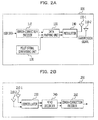
- Fig. 2A and Fig. 2B illustrate exemplary configurations of a transmitting apparatus and a receiving apparatus, respectively;
- Fig. 3 is a diagram illustrating an exemplary configuration of the receiving apparatus
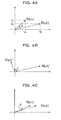
- Figs. 4A, 4B, and 4C depict examples of relationships between reception vectors and an angle
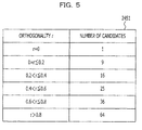
- Fig. 5 illustrates an example of a number-of-candidates determination table
- Fig. 6 is a flowchart illustrating an exemplary operation
- Fig. 7 is a diagram illustrating another exemplary configuration of the receiving apparatus
- Fig. 8 depicts an example of relationships between transmission signal points and a signal point
- Figs. 9A and 9B illustrate examples of the number-of-candidates determination table
- Fig. 10 is a flowchart illustrating an exemplary operation
- Fig. 11 is a diagram illustrating another exemplary configuration of the receiving apparatus.
- the amount of processing executed in a second stage varies significantly depending on the number of candidate points x 1 to be selected.
- the number of candidate points x 1 to be selected is constant since the values of the threshold and an upper limit are predetermined, In such a case, there may be cases in which the candidate points x 1 are not sufficiently narrowed down, and thus the amount of processing executed in the first and second stages may exceed a threshold.
- one object of the present invention is to provide a receiving apparatus and a receiving method which reduce the amount of processing.
- a receiving apparatus for estimating first and second transmission signals transmitted from respective first and second transmit antennas of a transmitting apparatus, based on first and second reception signals received by respective first and second receive antennas.
- the receiving apparatus includes a converting unit that multiplies first and second reception signal points for the respective first and second reception signals by a matrix and outputs resulting converted first and second reception signal points; a number-of-candidates determining unit that determines a number of candidates for at least first transmission-signal candidate points, based on a reception quality for the first and second reception signals; and an estimating unit that selects, based on the converted first and second reception signal points, the first transmission-signal candidate points and second transmission-signal candidate points, the number of first transmission-signal candidate points corresponding to the determined number of candidates, and that estimates, as the first and second transmission signals, the first and second transmission-signal candidate points with which distances between the selected first and second transmission-signal candidate points and the corresponding converted first and second reception signal points are smallest.
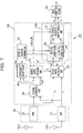
- Fig. 1 illustrates an exemplary configuration of a wireless communication system 10.
- the wireless communication system 10 has a transmitting apparatus 100 and a receiving apparatus 200.
- the transmitting apparatus 100 may be a radio base-station apparatus and the receiving apparatus 200 may be a terminal apparatus.
- the transmitting apparatus 100 may be a terminal apparatus and the receiving apparatus 200 may be a radio base-station apparatus.
- the transmitting apparatus 100 has n transmit antennas 150-1 to 150-n (where n is a natural number that satisfies n ⁇ 2 and the receiving apparatus 200 has m receive antennas 210-1 to 210-m (where m is a natural number that satisfies m ⁇ 2).
- the transmitting apparatus 100 and the receiving apparatus 200 can perform wireless communication based on a MIMO system by using the transmit antennas 150-1 to 150-n and the receive antennas 210-1 to 210-m.
- Fig. 2A and Fig. 2B are diagrams illustrating exemplary configurations of the transmitting apparatus 100 and the receiving apparatus 200, respectively.
- the transmitting apparatus 100 includes an error-correction encoder 110, a pilot-signal generating unit 120, a data mapping unit 130, a modulator 140, a first transmit antenna 150-1, and a second transmit antenna 150-2.
- the error-correction encoder 110 performs error-correction encoding processing on user data in accordance with a code rate, which may be predetermined.
- the error-correction encoder 110 outputs, for each of the first and second transmit antennas 150-1 and 150-2, encoded user data (hereinafter, encoded data) to the data mapping unit 130.
- the pilot-signal generating unit 120 generates a pilot signal (or a known signal) and outputs the pilot signal to the data mapping unit 130.
- the data mapping unit 130 maps bit sequences of the encoded data and the pilot signal onto transmission symbols (e.g., OFDM (orthogonal frequency division multiplexing) symbols).
- OFDM orthogonal frequency division multiplexing
- the modulator 140 performs modulation, which is based on a modulation system, on the transmission symbols output from the data mapping unit 130.
- modulation system examples include QPSK (Quadrature Phase Shift Keying), 16-QAM (Quadrature Amplitude Modulation), and 64-QAM.
- the modulator 140 performs IFFT (Inverse Fast Fourier Transform), and when the wireless communication system 10 is a CDMA (code division multiple access) system, the modulator 140 performs processing such as spreading.
- IFFT Inverse Fast Fourier Transform
- CDMA code division multiple access
- the modulator 140 outputs IFFT-processed transmission symbols to the first and second transmit antennas 150-1 and 150-2 as transmission signals.
- the first and second transmit antennas 150-1 and 150-2 respectively transmit different transmission signals to the receiving apparatus 200 as radio signals by using, for example, the same radio resources.
- the radio signals transmitted from the first transmit antenna 150-1 and the radio signals transmitted from the second transmit antenna 150-2 are referred to as a "first stream” and a "second stream", respectively, as needed.
- processing for separating the streams can be accomplished by an operation that is similar to the operation for a case of a one-to-one relationship.
- the receiving apparatus 200 includes a first receive antenna 210-1, a second receive antenna 210-2, a demodulator 230, a MIMO decoder 240, and an error-correction decoder 260.
- the first and second receive antennas 210-1 and 210-2 receive the radio signals transmitted from the transmitting apparatus 100 and output the received radio signals to the demodulator 230 as reception signals.
- the first receive antenna 210-1 receives the first stream transmitted from the first transmit antenna 150-1 and the second stream transmitted from the second transmit antenna 150-2.
- the second receive antenna 210-2 also receives the first stream and the second stream.
- the demodulator 230 performs demodulation processing, which is based on a modulation system (e.g., QPSK or 16-QAM), on the two reception signals received by the first and second receive antennas 210-1 and 210-2.
- the demodulator 230 performs FFT in the case of the OFDM system and performs despreading in the CDMA system. A description below is given in conjunction with an example of the OFDM system, as in the case of the transmitting apparatus 100.
- the demodulator 230 demodulates the reception signals received by the first and second receive antennas 210-1 and 210-2 and outputs the demodulated reception signals to the MIMO decoder 240.
- the MIMO decoder 240 executes first and second stages involving QRM-MLD on the demodulated reception signals, estimates transmission signal points x 0 and x 1 transmitted from the first and second antennas 150-1 and 150-2 of the transmitting apparatus 100, and outputs the estimated transmission signal points as transmission signals. Details of the MIMO decoder 240 are described below.
- the error-correction decoder 260 performs error-correction decoding processing on the transmission signals output from the MIMO decoder 240 and outputs, for example, user data.
- the demodulator 230, the MIMO decoder 240, and the error-correction decoder 260 may be digital circuits and may be implemented by, for example, an FPGA (Field Programmable Gate Array), an ASIC (Application Specific Integrated Circuit), or a DSP (Digital Signal Processor).
- the demodulator 230, the MIMO decoder 240, and the error-correction decoder 260 correspond to a converting unit, a number-of-candidates determining unit, and an estimating unit recited in the appended claims.
- MIMO decoder 240 Details of the MIMO decoder 240 will be described next. There are two exemplary cases, i.e., a case in which the MIMO decoder 240 performs sequential processing in a first stage and a second stage and a case in which the MIMO decoder 240 performs the first stage and the second stage in parallel. These two cases will be independently described as a first embodiment and a second embodiment.
- Fig. 3 is a diagram illustrating an exemplary configuration of the receiving apparatus 200, the configuration including an exemplary configuration of the MIMO decoder 240 in the first embodiment.
- the demodulator 230 has a first FFT unit 231 and a second FFT unit 232.
- the first and second FFT units 231 and 232 perform FFT processing on the reception signals output from the first and second receive antennas 210-1 and 210-2, respectively.
- the first and second FFT units 231 and 232 output FFT-processed data symbols r 0 and r 1 (hereinafter, reception signal points r 0 and r 1 ) to a reception-signal converting unit 243.
- the first and second FFT units 231 and 232 also output, for example, FFT-processed pilot signals to a channel estimating unit (or a reception-quality estimating unit) 241.
- the MIMO decoder 240 includes the channel estimating unit 241, a QR-decomposition matrix generating unit 242, a reception-signal converting unit 243, an orthogonality computing unit 244, a number-of-candidates determining unit 245, a first-stage computing unit 246, and a second-stage computing unit 247. Further, the MIMO decoder 240 may be implemented by a processor, the processor of, e.g., an FPGA (Field Programmable Gate Array), an ASIC (Application Specific Integrated Circuit) or a DSP (Digital Signal Processor).
- FPGA Field Programmable Gate Array
- ASIC Application Specific Integrated Circuit
- DSP Digital Signal Processor
- the channel estimating unit 241 performs, for example, averaging processing on the FFT-processed pilot signals and outputs resulting channel estimated values. For example, the channel estimating unit 241 outputs channel estimated values a 0 and c 0 with respect to the pilot signal received by the first receive antenna 210-1 and outputs channel estimated values b 0 and d 0 with respect to the pilot signal received by the second receive antenna 210-2.
- the reason why two channel estimated values a 0 and c 0 with respect to the pilot signal received by the first receive antenna 210-1 are output is that the reception signals received by the first receive antenna 210-1 contain two streams. The same also applies to the channel estimated values b 0 and d 0 .
- the QR-decomposition matrix generating unit 242 On the basis of the channel estimated values a 0 , c 0 , b 0 , and d 0 output from the channel estimating unit 241, the QR-decomposition matrix generating unit 242 generates a unitary matrix (or an orthogonal matrix) Q and an upper triangular matrix R in QR decomposition.
- the QR-decomposition matrix generating unit 242 outputs the unitary matrix Q to the reception-signal converting unit 243 and outputs the upper triangular matrix R to the orthogonality computing unit 244 and the first-stage computing unit 246.
- the QR-decomposition matrix generating unit 242 generates the two matrices Q and R, for example, in the following manner.
- the QR-decomposition matrix generating unit 242 generates a channel matrix H on the basis of the channel estimated values a 0 , c 0 , b 0 , and d 0 .
- the QR-decomposition matrix generating unit 242 can determine the upper triangular matrix R, for example, by substituting values into equations (9) to (11) with respect to the channel estimated values a 0 , c 0 , b 0 , and d 0 and can further determine elements of the unitary matrix Q by substituting the channel estimated values a 0 , c 0 , b 0 , and d 0 into equation (8).
- the reception-signal converting unit 243 multiplies the reception signal points r 0 and r 1 for the modulated reception signals, received by the first and second receive antennas 210-1 and 210-2, by the unitary matrix Q, to thereby convert the reception signals into signal points y 0 and y 1 , and outputs the signal points y 0 and y 1 .
- the MIMO wireless communication system 10 can be modeled as expressed by equation (1), and equation (1) is multiplexed from the left by the conjugate transpose matrix Q* of the unitary matrix Q to yield equation (4).
- reception-signal converting unit 243 converts a reception signal vector (r 0 , r 1 ) into (y 0 , y 1 ), a distance (or norm)
- 2 that includes the transmission signal point x 1 and does not include the transmission signal point x 0 can be calculated in the first stage involving QRM-MLD.
- the reception-signal converting unit 243 outputs the converted signals y 0 and y 1 to the second-stage and first-stage computing units 247 and 246, respectively.
- the orthogonality computing unit 244 outputs the computed orthogonality r to the number-of-candidates determining unit 245.
- the number-of-candidates determining unit 245 determines the number of candidates for the transmission signal point x 1 which are to be computed by the first-stage computing unit 246.
- a combination of the transmission signal points x 0 and x 1 with which the sum of expressions (14) and (15) is the smallest is determined. That is, in the second stage, the candidate points are selected from the candidate points for the transmission signal point x 1 which were selected in the first stage.
- the number of candidates for the transmission signal point x 1 selected in the first stage is narrowed down to within a range in which no inversion occurs.
- the term "inversion" refers to a case in which the candidate points of the transmission signal point x 1 selected in the second stage are candidate points other than the candidate points selected in the first stage.
- the number-of-candidates determining unit 245 determines the number of candidates for the transmission signal point x 1 .
- the magnitude of expression (14) varies according to the magnitude of x 1 and the degree of the variation depends on the magnitude of the coefficient c of x 1 .
- the magnitude of expression (14) has a value, such as 100 2 or 300 2 , that varies greatly depending on the value of x 1 .
- x 1 with which the magnitude of expression (14) is the smallest is selected as a candidate point, it is highly likely that the selected candidate point is also the most favorable candidate point in the second stage, since differences relative to the magnitude of expression (14) with respect to other candidates are large.
- the probability that the above-described inversion occurs is smaller than a threshold even when the number of candidates for x 1 is narrowed down.
- the magnitude of expression (14) changes to, for example, 1 2 , 3 2 , and so on, which is smaller than a case in which c is 100, no matter how x 1 is selected.
- the inversion can occur since differences relative to the candidate points in expression (14) are small compared to the case in which c is 100.
- a larger number of candidates than in the case in which c is 100 may be selected.
- x 1 is dependent on the magnitude of the coefficient b.
- the magnitude of equation (15) can assume a value that varies greatly according to the magnitude of x 1 .
- equation (15) has a value that varies greatly depending on x 1 selected in the first stage.
- a larger number of candidates for x 1 than the threshold may be selected in the first stage, taking the above-described inversion into account.
- the magnitude of equation (15) varies in a small range of values compared to the case in which b is larger than the threshold, regardless of the selection of x 1 .
- the number of candidates for x 1 selected in the first stage may be set smaller than the threshold. For example, when b is 0, x 1 selected in expression (14) is the most favorable x 1 (in this case, the number of candidates is 1), the magnitude of (15) becomes independent from x 1 , and candidate points of another transmission signal point x 0 are selected in the second stage.
- the number of candidates for x 1 selected in the first and second stages is dependent on the coefficients b and c in the first and second stages.
- the number of candidates is determined according to the value of
- the influence the selection of x 1 in the first stage has on the second stage depends on the magnitude of the coefficient b in equation (15). That is, since the ultimate value of x 1 is selected in the second stage, the coefficient b has a larger degree of influence on distance calculation in each stage than the coefficient c. Thus, the inversion is more likely to occur depending on the magnitude of b.
- an amount corresponding to ⁇ is used as an orthogonality r.
- Figs. 4A to 4C depict examples of relationships between two vectors A and B and the angle ⁇ .
- ⁇ is 90° (or the vectors A and B are orthogonal to each other, for example, as depicted in Fig. 4B )
- the orthogonality r is 0, and when ⁇ is 0° (or the vectors A and B are parallel to each other or the degree of orthogonality is the smallest, for example, as depicted in Fig. 4C ), the orthogonality r is infinite.
- the orthogonality r is 0 when two vectors A and B are orthogonal to each other.
- r can also be regarded as an amount associated with the degree of the orthogonality of two vectors A and B.
- the degree of influence of the candidate points of the transmission signal point x 1 which are selected in the first stage and the degree of influence of the candidate points of the transmission signal point x 0 which are selected in the second stage are smaller than a threshold, and the candidate points of two transmission signal points x 0 and x 1 can be selected independently in the respective stages. In such a case, it can be said that two transmission signal points x 0 and x 1 can be easily separated.
- b/c indicating the orthogonality r represents, for example, ease of separation of two transmission streams.
- two transmission streams can be easily decomposed i.e., when the orthogonality r is larger than the threshold
- the reception quality is not favorable.
- the number-of-candidates determining unit 245 determines the number candidates such that, for example, when the reception quality is more favorable than the threshold, the number of candidates for the candidate points of the transmission signal point x 1 is smaller than the threshold and, when the reception quality is less favorable than the threshold, the number of candidates is larger than the threshold.
- the reception quality is, for example, an index indicating ease of separation of a plurality of transmission streams into discrete streams.
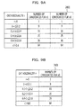
- Fig. 5 illustrates an example of a number-of-candidates determination table 2451 held by the number-of-candidates determining unit 245.
- the modulation system is 64QAM.
- the number-of-candidates determination table 2451 has an "orthogonality" field and a "number of candidates" field, in which the number of candidates is stored for each orthogonality.
- the number-of-candidates determining unit 245 refers to the number-of-candidates determination table 2451 to read the number of candidates which corresponds to the orthogonality r output from the orthogonality computing unit 244, and outputs the read number of candidates to the first-stage computing unit 246.
- the number-of-candidates determination table 2451 when the orthogonality is 0, two transmission streams can be easily separated (i.e., the reception quality is favorable) and the number of candidates is 1, which is the smallest number.
- the orthogonality is larger than 0.8, it is difficult to separate two transmission streams (i.e., the reception quality is not favorable) and the number of candidates is 64, which is the largest number.
- the first-stage computing unit 246 selects candidate points for x 1 , the number of candidate points corresponding to the number of candidates. That is, the first-stage computing unit 246 selects, in ascending order of the value of expression (14), the candidate points for the transmission signal point x 1 which correspond to the number of candidates determined by the number-of-candidates determining unit 245. The first-stage computing unit 246 outputs, to the second-stage computing unit 247, the candidate points of the transmission signal point x 1 which correspond to the number of candidates.
- the second-stage computing unit 247 selects one or multiple candidate points for the transmission signal point x 0 such that the value of expression (15) is smaller than a threshold.
- the second-stage computing unit 247 estimates, as the transmission signal points x 0 and x 1 , the candidate points with which the sum of expression (14) and expression (15) is the smallest, and outputs the estimated transmission signal points x 0 and x 1 .
- An estimating unit 2460 estimates the signal points x 0 and x 1 of the two transmission signals, and may have the first-stage and second-stage computing units 246 and 247.
- the error-correction decoder 260 performs error-correction decoding processing on the transmission signal points x 0 and x 1 .
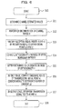
- Fig. 6 is a flowchart illustrating an exemplary operation.
- the receiving apparatus 200 starts processing in operation S10 and determines channel estimated values in operation S11.
- the channel estimating unit 241 determines channel estimated values a 0 , c 0 , b 0 , and d 0 on the basis of demodulated pilot signals.
- the receiving apparatus 200 performs QR decomposition on a channel matrix H.
- the QR-decomposition matrix generating unit 242 generates an upper triangular matrix R (e.g., equation (8)) and a unitary matrix Q (e.g., equation (7) and equations (9) to (11)) with respect to the channel matrix H.
- the receiving apparatus 200 multiplies reception signal points r 0 and r 1 by the unitary matrix Q to obtain signal points y 0 and y 1 .
- the reception-signal converting unit 243 multiplies the reception signal points r 0 and r 1 by the unitary matrix Q output from the QR-decomposition matrix generating unit 242, to obtain the signal points y 0 and y 1 (e.g., equation (12)).
- the receiving apparatus 200 computes an orthogonality r on the basis of the upper triangular matrix R.
- the orthogonality computing unit 244 computes the orthogonality r (e.g., equation (13)) by computing the ratio (e.g., "b/c") of the diagonal element versus the off-diagonal element with respect to the matrix R output from the QR-decomposition matrix generating unit 242.
- the receiving apparatus 200 determines the number of candidates on the basis of the orthogonality r. For example, by referring to the number-of-candidates determination table 2451, the number-of-candidates determining unit 245 selects the number of candidates which corresponds to the orthogonality r.
- the receiving apparatus 200 may perform the processing in operations S14 and S15 prior to the processing in operation S13.
- the receiving apparatus 200 computes candidate points of the transmission signal point x 1 which correspond to the determined number of candidates.
- the first-stage computing unit 246 computes, in ascending order of the distance
- the receiving apparatus 200 determines the transmission signal points x 0 and x 1 .
- the second-stage computing unit 247 computes, in ascending order of the distance
- the orthogonality r is the ratio (b/c) of the diagonal element in the upper triangular matrix R.
- the orthogonality r may be c/b.
- the number-of-candidates determining unit 245 selects the number of candidates which is larger than a threshold, and when the orthogonality r is smaller than or equal to the threshold (i.e., when the reception quality is favorable), the number-of-candidates determining unit 245 selects the number of candidates which is smaller than or equal to the threshold.
- the second embodiment is an example in which the first and second stages are executed in parallel and is similar to the first embodiment in that the number of candidates to be selected is varied based on the orthogonality (or the reception quality).
- Fig. 7 is a diagram illustrating an exemplary configuration of the receiving apparatus 200 including the MIMO decoder 240.
- the MIMO decoder 240 includes an inverse-matrix generating unit 251, an inverse-matrix multiplying unit 252, and a total-distance calculating and estimating unit (hereinafter, a total-distance calculating unit) 253.
- the inverse-matrix generating unit 251 generates an inverse matrix H -1 of the channel matrix H on the basis of the channel estimated values a 0 , c 0 , b 0 , and d 0 .
- the inverse-matrix multiplying unit 252 multiplies the reception signal points r 0 and r 1 by the inverse matrix H -1 output from the inverse-matrix generating unit 251, and outputs the resulting signal points r 0 ' and r 1 ' to the first-stage and second-stage computing units 246 and 247, respectively.
- the inverse-matrix generating unit 251 computes the inverse matrix H -1 and the inverse-matrix multiplying unit 252 multiplies the reception signal points r 0 and r 1 by the inverse matrix H -1 , as described above, for, for example, the following reason.
- H - 1 1 a 0 ⁇ d 0 - b 0 ⁇ c 0 ⁇ d 0 - b 0 - c 0 a 0
- the candidate points of the transmission signal points x 0 and x 1 can be computed independently.
- the inverse-matrix multiplying unit 252 computes equations (20) to (25) and outputs the resulting r 0 ' and r 1 '.
- the first-stage computing unit 246 determines, in ascending order of a distance
- the first-stage computing unit 246 also determines distances l 0 between the determined candidate points and the signal point r 0 '.
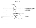
- Fig. 8 depicts an example of relationships between a transmission signal point x 0 and a signal point r 0 '.
- the number of candidates is 5, so that five candidate points x 0-1 to x 0-5 are selected and five distances l 0-1 to l 0-5 are computed.
- the first-stage computing unit 246 can compute a number of candidate points corresponding to the number of candidates, for example, by using an area determination method.
- a total-distance calculating unit 253 is adapted to calculate a square sum of the elements of equation (26) as a total distance L and to select the candidate points of the transmission signal points x 0 and x 1 such that the total distance L becomes the smallest.
- the candidate points of the transmission signal points x 0 and x 1 with which the total distance L is the smallest are candidate points with which the distances between the candidate points and the corresponding reception signal points r 0 and r 1 are the smallest in the same vector space as for the reception signal points r 0 and r 1 .
- the total-distance calculating unit 253 computes the candidate points with which the total distance L is the smallest.
- the estimating unit 2460 for estimating two transmission signal points x 0 and x 1 may have, for example, the first-stage and second-stage computing units 246 and 247 and the total-distance calculating unit 253.
- the first and second first-stage computing units 246 and 247 independently compute the candidate points with which the distance is the smallest, but also the total-distance calculating unit 253 computes the candidate points with which the total distance L becomes the smallest, on the basis of those candidate points.
- the numerator of equation (28) includes channel estimated values a 0 , c 0 , b 0 , and d 0 , and is computed using the pilot signals for two transmission streams, and is (or corresponds to) the inner product of two reception vectors for the reception signal points r 0 and r 1 .
- the reception signal points r 0 and r 1 include components of two transmission signal points, a reception vector for the reception signal point r 0 and a reception vector for the reception signal point r 1 exist.
- the numerator of equation (28) assumes a value of 0, when two reception vectors are orthogonal to each other, and assumes a larger value than a threshold as two reception vectors approach parallel to each other.
- Equation (28) yields an addition value obtained by adding the magnitude (
- equation (28) generally indicates, for example, the ratio of the addition value of the magnitudes of two reception vectors versus the inner product of two reception vectors.
- the number-of-candidates determining unit 245 uses the orthogonality r to determine the number of candidates for the candidate points for each of the transmission signal points x 0 and x 1 , the candidate points being to be selected by the first-stage and second-stage computing units 246 and 247.
- the number-of-candidates determination table 2451 since the number-of-candidates determining unit 245 determines two numbers of candidates, the number-of-candidates determination table 2451 has a form corresponding thereto.
- Fig. 9A and 9B illustrate examples of the number-of-candidates determination table 2451. As illustrated in Fig.
- the number of candidates for the transmission signal point x 0 and the number of candidates for the transmission signal point x 1 may be stored independently from each other.
- the number of candidates for the transmission signal point x 1 and the number of candidates for the transmission signal point x 0 may be stored in different tables 2451 (e.g., the number-of-candidates determination table 2451 illustrated in Fig. 5 and the number-of-candidates determination table 2451 illustrated in Fig. 9B ) so as to correspond to the orthogonality r.
- the threshold controller 200 starts processing in operation S20 and determines channel estimated values in operation S21.
- the channel estimating unit 241 determines channel estimated values a 0 , c 0 , b 0 , and d 0 on the basis of pilot signals, as in the first embodiment.
- the receiving apparatus 200 determines an inverse matrix H -1 of a channel matrix H. For example, on the basis of the channel estimated values a 0 , c 0 , b 0 , and d 0 , the inverse-matrix generating unit 251 uses equation (19) to compute the inverse matrix H -1 .
- the number-of-candidates determining unit 245 determines the number of candidates for each of the transmission signal points x 0 and x 1 such that the number of candidates is larger than the threshold.
- the receiving apparatus 200 determines the candidate points of the transmission signal points x 0 and x 1 , the number of candidate points corresponding to the number of candidates, and distances l 0 and l 1 (i.e., distances between the candidate points and the corresponding signal points r 0 ' and r 1 '), the number of distances corresponding to the number of candidates.
- the first-stage and second-stage computing units 246 and 247 compute the candidate points and the distances, the number of which corresponds to the number of candidates, in ascending order of the distance
- the receiving apparatus 200 computes total distances L on the basis of the distances l 0 and l 1 and the channel estimated values a 0 , c 0 , b 0 , and d 0 .
- the total-distance calculating unit 253 uses equation (27) to compute a number of total distances L which corresponds to the number of candidates.
- the receiving apparatus 200 determines, as transmission signal points x 0 and x 1 , a combination of the candidate points with which the total distance L is the smallest.
- the total-distance calculating unit 253 determines, as the transmission signal points x 0 and x 1 , the candidate points with which the smallest of the total distances L is obtained, the number of total distances corresponding to the number of candidates.
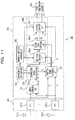
- Fig. 11 illustrates another exemplary configuration of the receiving apparatus 200.
- the receiving apparatus 200 includes first to nth receive antennas 210-1 to 210-n, first to nth FFT units 230-1 to 230-n, and first-stage to nth-stage computing units 246-1 to 246-n.
- the first to nth receive antennas 210-1 to 210-n output reception signals to the first to nth FFT units 230-1 to 230-n.
- the channel estimating unit 241 outputs channel estimated values for the respective receive antennas 210-1 to 210-n (or for the respective transmission streams 1 to n) to the QR-decomposition matrix generator 242.
- the QR-decomposition matrix generating unit 242 On the basis of the channel estimated values, the QR-decomposition matrix generating unit 242 generates a channel matrix H and performs QR decomposition thereon to generate a matrix R.
- the QR-decomposition matrix generating unit 242 then outputs the matrix R to the orthogonality computing unit 244.
- the number-of-candidates determining unit 245 determines the number of candidates for x n-k+1 to be selected in the kth stage such that the number of candidates is larger than a second threshold.
- the number-of-candidates determining unit 245 determines the number of candidates for x n-k+1 to be selected in the kth stage such that the number of candidates is smaller than or equal to the second threshold.
- the first-stage to nth-stage computing units 246-1 to 246-n select candidate points of the transmission signal points x n to x 1 , the candidate points corresponding to the respective determined numbers of candidates. For example, the kth-stage computing unit 246-k selects candidate points of the transmission signal point x n-k+1 which corresponds to the determined number of candidates, and outputs the selected candidate points to the (k+1)th-stage computing unit 246-(k+1) in conjunction with the candidate points for the transmission signal points x 1 to x n . The nth-stage computing unit 246-n outputs the candidate points of the n transmission signal points x 1 to x n . For example, the first-stage to nth-stage computing units 246-1 to 246-n may constitute the estimating unit 2460.
- the first-stage computing unit 246-1 selects x 3 corresponding to the number of candidates such that expression (32) below is smaller than or equal to a threshold. y 1 - f ⁇ x 3 2
- the second-stage computing unit 246-2 selects x 2 corresponding to the number of candidates such that expression (33) below is smaller than or equal to a threshold. y 1 - f ⁇ x 3 2 + y 2 - d ⁇ x 2 - e ⁇ x 3 2
- the third-stage computing unit 246-3 further selects x 1 corresponding to the number of candidates such that expression (34) below is smaller than or equal to a threshold.
- Equation (36) also indicates that the number of candidates for x 3 selected in the first stage is dependent on the coefficient f of x 3 selected in the first stage, the coefficient e of x 3 in the second stage, and the coefficient c of x 3 in the third stage.
- the orthogonality r indicted by equation (37) takes into account the degree of influence (e.g., the coefficient e in the second stage) of x k on the distance calculation in the (k+1)th stage, but does not take into account the influence (e.g., the coefficient c in the third stage) on the distance calculation in the (k+2)th and subsequent stages. Since the influence on the stage after the next is not considered in the current stage, the amount of calculation can be reduced compared to the case of equation (30).
- Equation (37) when the vectors A 1 to A n-k+1 are orthogonal (or when the reception quality is more favorable than the threshold), r is equal to 0, and when the vectors are parallel, r is infinite.
- the orthogonality computing unit 244 computes the orthogonality r by using equation (37), and the number-of-candidates determining unit 245 determines the number of candidates for each stage in accordance with the orthogonality r, in the same manner as described above.
- the orthogonality r is also expressed as a ratio of the diagonal element (e.g., the coefficient f) versus the off-diagonal element (e.g., the coefficients c and e) in the matrix R resulting from the QR decomposition.
- Equation (39) indicates, for example, the degree of influence the candidate points of x which were selected in the first to kth stages has on the (k+1)th and subsequent stages.
- the candidate points with which the cumulative distance is smaller than or equal to C ⁇ r (C is a constant) are selected, as the ultimate candidate points, from the candidate points with which the cumulative distances are smallest up to the third stages.
- the ultimate candidate points are used for the distance computation.
- the cumulative distance is, for example, the sum of distances calculated up to the kth stage (or the distance calculated in the kth stage).
- the cumulative distance is, for example, the sum of a distance (
- the cumulative distance is 10 when (1, 3) are selected as a set (x 3 , x 2 ) of candidate points, the cumulative distance is 15 when the candidate points (-1, 1) are selected, and the cumulative distance is 50 when the candidate points (-1, -1) are selected.
- n 1 to n 3 denote noise components.
- the first-stage computing unit 246-1 selects x 2 corresponding to the number of candidates such that expression (43) below is smaller than a threshold. y 3 - e ⁇ x 2 2
- the second-stage computing unit 246-2 selects x 2 and x 1 corresponding to the number of candidates such that expression (44) below is smaller than a threshold. y 3 - e ⁇ x 2 2 + y 2 - c ⁇ x 1 - d ⁇ x 2 2
- the third-stage computing unit 246-3 selects x 1 and x 2 such that expression (45) below is the smallest. y 3 - e ⁇ x 2 2 + y 2 - c ⁇ x 1 - d ⁇ x 2 2 + y 1 - a ⁇ x 1 - b ⁇ x 2 2
- the third-stage computing unit 246-3 cannot newly select x 1 and x 2 and thus computes the distances on the basis of the candidates of x 1 and x 2 selected by the second-stage computing unit 246-2.
- n no new candidate points of the transmission signal point x are selected in the halfway and subsequent stages and thus the distances with respect to x i selected in the stages prior to the halfway stage are calculated.
- the number-of-candidates determining unit 245 can also determine the number of candidates for each subcarrier. For example, as illustrated in Fig. 3 , the first and second FFT units 231 and 232 output transmission signal points r 0 and r 1 for each subcarrier and the reception-signal converting unit 243 outputs the converted signal points y 1 and y 0 for each subcarrier.
- the orthogonality computing unit 244 can compute the orthogonality r for each subcarrier.
- the total number of candidates can be made constant according to the number of subcarriers decoded by the error-correction decoder 260. For example, when the number of subcarriers is 5, the total number of candidates assigned to the first to fifth subcarriers may be set to 100, for example, with the number of candidates for the candidate points of the transmission signal point x 1 with respect to the first subcarrier being set to 10, the number of candidates with respect to the second subcarrier being set to 17, and so on.
- Such an arrangement can make the number of processible candidates in the entire receiving apparatus 200 to be constant, can facilitate circuit design, and can also make the circuit scale smaller than a certain size.
- the inverse-matrix multiplying unit 252 can output the signal points r 0 ' and r 1 ' for each subcarrier and the number-of-candidates determining unit 245 can determine the number of candidates for the transmission signal points x 1 and x 0 for each subcarrier, as illustrated in Fig. 7 .
- the invention also provides a computer program or a computer program product for carrying out any of the methods described herein, and a computer readable medium having stored thereon a program for carrying out any of the methods described herein.
- a computer program embodying the invention may be stored on a computer-readable medium, or it could, for example, be in the form of a signal such as a downloadable data signal provided from an Internet website, or it could be in any other form.
- a receiving apparatus for estimating first and second transmission signals transmitted from respective first and second transmit antennas of a transmitting apparatus, based on first and second reception signals received by respective first and second receive antennas, the receiving apparatus comprising:
Landscapes
- Engineering & Computer Science (AREA)
- Signal Processing (AREA)
- Computer Networks & Wireless Communication (AREA)
- Power Engineering (AREA)
- Physics & Mathematics (AREA)
- Mathematical Physics (AREA)
- Radio Transmission System (AREA)
- Mobile Radio Communication Systems (AREA)
- Radar Systems Or Details Thereof (AREA)
Applications Claiming Priority (1)
| Application Number | Priority Date | Filing Date | Title |
|---|---|---|---|
| JP2010121790A JP5691245B2 (ja) | 2010-05-27 | 2010-05-27 | 受信装置、及び受信方法 |
Publications (2)
| Publication Number | Publication Date |
|---|---|
| EP2391047A2 true EP2391047A2 (de) | 2011-11-30 |
| EP2391047A3 EP2391047A3 (de) | 2015-01-07 |
Family
ID=44195548
Family Applications (1)
| Application Number | Title | Priority Date | Filing Date |
|---|---|---|---|
| EP11164959.6A Withdrawn EP2391047A3 (de) | 2010-05-27 | 2011-05-05 | Verfahren zum Einschätzen eines empfangenen Signals und entsprechende Vorrichtung |
Country Status (3)
| Country | Link |
|---|---|
| US (1) | US8369441B2 (de) |
| EP (1) | EP2391047A3 (de) |
| JP (1) | JP5691245B2 (de) |
Families Citing this family (6)
| Publication number | Priority date | Publication date | Assignee | Title |
|---|---|---|---|---|
| JP5630234B2 (ja) * | 2010-11-19 | 2014-11-26 | 富士通株式会社 | 信号処理方法及び受信機 |
| CN107196728B (zh) * | 2011-06-28 | 2019-07-09 | 索尼公司 | 通信方法、通信装置、终端 |
| JP6015372B2 (ja) * | 2012-11-15 | 2016-10-26 | 富士通株式会社 | 無線通信装置、及び無線通信方法 |
| ES2905440T3 (es) * | 2017-07-27 | 2022-04-08 | Beijing Xiaomi Mobile Software Co Ltd | Método y dispositivo para controlar interferencias |
| CN111371478B (zh) * | 2018-12-26 | 2021-10-15 | 华为技术有限公司 | 预编码方法和装置及信息传输方法和装置 |
| CN115695560B (zh) * | 2021-07-23 | 2024-11-08 | 伊姆西Ip控股有限责任公司 | 内容分发方法、电子设备和计算机程序产品 |
Citations (1)
| Publication number | Priority date | Publication date | Assignee | Title |
|---|---|---|---|---|
| JP2010121790A (ja) | 2008-11-17 | 2010-06-03 | Toyota Motor Corp | 熱処理方法及び熱処理装置 |
Family Cites Families (13)
| Publication number | Priority date | Publication date | Assignee | Title |
|---|---|---|---|---|
| JP4536495B2 (ja) * | 2004-11-29 | 2010-09-01 | 株式会社エヌ・ティ・ティ・ドコモ | 信号分離装置及び信号分離方法 |
| JP4290660B2 (ja) * | 2005-02-14 | 2009-07-08 | 日本電信電話株式会社 | 空間多重信号検出回路及び空間多重信号検出方法 |
| JP4429945B2 (ja) | 2005-03-23 | 2010-03-10 | 株式会社エヌ・ティ・ティ・ドコモ | Mimo多重通信装置および信号分離方法 |
| US7817740B2 (en) * | 2006-02-09 | 2010-10-19 | Broadcom Corporation | Method and system for minimum mean squared error soft interference cancellation (MMSE-SIC) based suboptimal maximum likelihood (ML) detection for multiple input multiple output (MIMO) wireless system |
| CN101390322A (zh) * | 2006-02-22 | 2009-03-18 | 高通股份有限公司 | 借助于信道id发送信令信息的方法与装置 |
| FR2913160B1 (fr) * | 2007-02-27 | 2009-05-22 | Commissariat Energie Atomique | Decodeur a maximum de vraisemblance pour systeme multi-source a modulation de position d'impulsion |
| FR2913161B1 (fr) * | 2007-02-27 | 2009-05-22 | Commissariat Energie Atomique | Decodeur a maximum de vraisemblance pour systeme multi-source a modulation de position d'impulsion et d'amplitude |
| JP2008228145A (ja) | 2007-03-15 | 2008-09-25 | Kddi Corp | マルチユーザmimoシステムにおける受信機、制御プログラム及び受信制御方法 |
| JP4802148B2 (ja) | 2007-06-29 | 2011-10-26 | 日本電信電話株式会社 | 信号検出装置及び信号検出方法並びにそのプログラムと記録媒体 |
| CN101383797B (zh) * | 2007-09-03 | 2012-12-26 | 富士通株式会社 | 用于mimo系统的低复杂度的信号检测方法和检测装置 |
| KR100943519B1 (ko) * | 2007-11-22 | 2010-02-22 | 한국전자통신연구원 | 로그우도비 산출 방법 및 송신 신호 검출 방법 |
| TWI424699B (zh) * | 2008-08-31 | 2014-01-21 | Realtek Semiconductor Corp | 多層叢集式多輸入多輸出偵測方法及相關多輸入多輸出偵測器 |
| EP2340621B1 (de) * | 2008-10-31 | 2012-12-05 | Telefonaktiebolaget L M Ericsson (publ) | Kanalunterstützte iterative vorcodiererauswahl |
-
2010
- 2010-05-27 JP JP2010121790A patent/JP5691245B2/ja not_active Expired - Fee Related
-
2011
- 2011-04-22 US US13/092,362 patent/US8369441B2/en not_active Expired - Fee Related
- 2011-05-05 EP EP11164959.6A patent/EP2391047A3/de not_active Withdrawn
Patent Citations (1)
| Publication number | Priority date | Publication date | Assignee | Title |
|---|---|---|---|---|
| JP2010121790A (ja) | 2008-11-17 | 2010-06-03 | Toyota Motor Corp | 熱処理方法及び熱処理装置 |
Also Published As
| Publication number | Publication date |
|---|---|
| JP2011250179A (ja) | 2011-12-08 |
| US20110292983A1 (en) | 2011-12-01 |
| JP5691245B2 (ja) | 2015-04-01 |
| US8369441B2 (en) | 2013-02-05 |
| EP2391047A3 (de) | 2015-01-07 |
Similar Documents
| Publication | Publication Date | Title |
|---|---|---|
| EP2267925B1 (de) | Mobilkommunikationssystem, empfangsgerät und verfahren dafür | |
| JP5122428B2 (ja) | 移動通信システム、受信装置及び方法 | |
| US20080008258A1 (en) | Wireless receiving apparatus and method | |
| US9362995B2 (en) | Transmitter apparatus, receiver apparatus, communication system, communication method, and integrated circuit | |
| WO2008025397A1 (en) | Equalizing structure and equalizing method | |
| EP2391047A2 (de) | Verfahren zum Einschätzen eines empfangenen Signals und entsprechende Vorrichtung | |
| JP5053377B2 (ja) | 等化構造及び等化方法 | |
| US20080181335A1 (en) | Wireless communication apparatus | |
| US8249196B2 (en) | Equalizing structure and equalizing method | |
| US20170117944A1 (en) | Systems and Methods for Detecting Data in a Received multiple-Input-Multiple-Output (MIMO) Signal | |
| US8259855B2 (en) | Equalizing structure and equalizing method | |
| US8619893B2 (en) | Receiving apparatus and receiving method | |
| US20080181324A1 (en) | Systems and methods for scaling to equalize noise variance | |
| US20170118050A1 (en) | Systems and Methods for Detecting Data in a Received Multiple-Input-Multiple-Output (MIMO) Signal | |
| JP5121552B2 (ja) | 受信装置 | |
| JP4290657B2 (ja) | 空間分割多重信号検出回路および空間分割多重信号検出方法 | |
| US9525456B2 (en) | Receiving device and receiving process method | |
| KR20120065884A (ko) | Mimo-ofdm 시스템에서 신호 수신 장치 및 방법 |
Legal Events
| Date | Code | Title | Description |
|---|---|---|---|
| AK | Designated contracting states |
Kind code of ref document: A2 Designated state(s): AL AT BE BG CH CY CZ DE DK EE ES FI FR GB GR HR HU IE IS IT LI LT LU LV MC MK MT NL NO PL PT RO RS SE SI SK SM TR |
|
| AX | Request for extension of the european patent |
Extension state: BA ME |
|
| PUAI | Public reference made under article 153(3) epc to a published international application that has entered the european phase |
Free format text: ORIGINAL CODE: 0009012 |
|
| PUAL | Search report despatched |
Free format text: ORIGINAL CODE: 0009013 |
|
| AK | Designated contracting states |
Kind code of ref document: A3 Designated state(s): AL AT BE BG CH CY CZ DE DK EE ES FI FR GB GR HR HU IE IS IT LI LT LU LV MC MK MT NL NO PL PT RO RS SE SI SK SM TR |
|
| AX | Request for extension of the european patent |
Extension state: BA ME |
|
| RIC1 | Information provided on ipc code assigned before grant |
Ipc: H04L 5/00 20060101AFI20141201BHEP Ipc: H04L 25/03 20060101ALI20141201BHEP |
|
| 17P | Request for examination filed |
Effective date: 20150519 |
|
| RBV | Designated contracting states (corrected) |
Designated state(s): AL AT BE BG CH CY CZ DE DK EE ES FI FR GB GR HR HU IE IS IT LI LT LU LV MC MK MT NL NO PL PT RO RS SE SI SK SM TR |
|
| STAA | Information on the status of an ep patent application or granted ep patent |
Free format text: STATUS: THE APPLICATION HAS BEEN WITHDRAWN |
|
| 18W | Application withdrawn |
Effective date: 20180108 |