EP2390708A1 - Am Kopf angebrachte Anzeige - Google Patents
Am Kopf angebrachte Anzeige Download PDFInfo
- Publication number
- EP2390708A1 EP2390708A1 EP10164105A EP10164105A EP2390708A1 EP 2390708 A1 EP2390708 A1 EP 2390708A1 EP 10164105 A EP10164105 A EP 10164105A EP 10164105 A EP10164105 A EP 10164105A EP 2390708 A1 EP2390708 A1 EP 2390708A1
- Authority
- EP
- European Patent Office
- Prior art keywords
- image
- light
- display unit
- visible light
- image data
- Prior art date
- Legal status (The legal status is an assumption and is not a legal conclusion. Google has not performed a legal analysis and makes no representation as to the accuracy of the status listed.)
- Withdrawn
Links
- 210000001508 eye Anatomy 0.000 claims abstract description 12
- 238000004040 coloring Methods 0.000 claims abstract description 4
- 230000005540 biological transmission Effects 0.000 claims description 13
- 210000005252 bulbus oculi Anatomy 0.000 claims description 13
- 239000003086 colorant Substances 0.000 claims description 9
- 210000001142 back Anatomy 0.000 claims description 3
- 230000003287 optical effect Effects 0.000 description 8
- 230000000007 visual effect Effects 0.000 description 7
- 210000001525 retina Anatomy 0.000 description 6
- 230000000903 blocking effect Effects 0.000 description 4
- 238000001093 holography Methods 0.000 description 4
- 208000032041 Hearing impaired Diseases 0.000 description 2
- 208000010415 Low Vision Diseases 0.000 description 2
- 230000004303 low vision Effects 0.000 description 2
- 238000000034 method Methods 0.000 description 2
- 239000010409 thin film Substances 0.000 description 2
- 201000009310 astigmatism Diseases 0.000 description 1
- 230000001427 coherent effect Effects 0.000 description 1
- 238000007796 conventional method Methods 0.000 description 1
- 238000010586 diagram Methods 0.000 description 1
- 230000000694 effects Effects 0.000 description 1
- 230000004438 eyesight Effects 0.000 description 1
- 239000011521 glass Substances 0.000 description 1
- 239000004973 liquid crystal related substance Substances 0.000 description 1
- 208000001491 myopia Diseases 0.000 description 1
- 230000004379 myopia Effects 0.000 description 1
- 239000000049 pigment Substances 0.000 description 1
- 210000001747 pupil Anatomy 0.000 description 1
- 238000004088 simulation Methods 0.000 description 1
- 238000001228 spectrum Methods 0.000 description 1
Images


Classifications
-
- G—PHYSICS
- G02—OPTICS
- G02B—OPTICAL ELEMENTS, SYSTEMS OR APPARATUS
- G02B27/00—Optical systems or apparatus not provided for by any of the groups G02B1/00 - G02B26/00, G02B30/00
- G02B27/01—Head-up displays
- G02B27/017—Head mounted
- G02B27/0172—Head mounted characterised by optical features
-
- G—PHYSICS
- G02—OPTICS
- G02B—OPTICAL ELEMENTS, SYSTEMS OR APPARATUS
- G02B27/00—Optical systems or apparatus not provided for by any of the groups G02B1/00 - G02B26/00, G02B30/00
- G02B27/01—Head-up displays
- G02B27/0101—Head-up displays characterised by optical features
- G02B2027/0112—Head-up displays characterised by optical features comprising device for genereting colour display
- G02B2027/0114—Head-up displays characterised by optical features comprising device for genereting colour display comprising dichroic elements
-
- G—PHYSICS
- G02—OPTICS
- G02B—OPTICAL ELEMENTS, SYSTEMS OR APPARATUS
- G02B27/00—Optical systems or apparatus not provided for by any of the groups G02B1/00 - G02B26/00, G02B30/00
- G02B27/01—Head-up displays
- G02B27/0101—Head-up displays characterised by optical features
- G02B2027/0118—Head-up displays characterised by optical features comprising devices for improving the contrast of the display / brillance control visibility
-
- G—PHYSICS
- G02—OPTICS
- G02B—OPTICAL ELEMENTS, SYSTEMS OR APPARATUS
- G02B5/00—Optical elements other than lenses
- G02B5/20—Filters
Definitions
- This invention relates to a display unit in which images taken by a camera or photographs or video images based on external data are displayed before the eyes of a person by a display device.
- Japanese Published Unexamined Patent Application No. 2006-85011 or Japanese Published Unexamined Patent Application No. 2006-98827 can be mentioned as an example of a display device that adopts holography.
- a retina scanning display device that displays images directly on a retina of a user can also be used as another transmissive display device.
- these display devices are adapted, it is conceivable to use these devices for low-vision or visually-impaired persons.
- the scenery around (especially, in front of) a visually-impaired person who is a user is imaged by a camera, and is displayed before the eyes of the user by a display device so as to be used as visual assistance.
- a display device so as to be used as visual assistance.
- FIG. 9 or that of FIG. 10 is conceived as a display unit for visual assistance in which sunglass lenses are used together.
- FIG. 9 is a view showing an example of a display unit using a transmissive display device that adopts holography.
- a sunglass lens 101 is disposed on the outermost side (i.e., on the object side) of this display unit, and a transmissive display device 102 is disposed inside the sunglass lens 101.
- a corrective lens 105 is disposed inside the transmissive display device 102 (i.e. , disposed closer to the eyeball).
- the transmissive display device 102 includes a transparent board and an image projecting part 104 disposed on the upper part of the board. In the transmissive display device 102, both a real image that has passed through the transparent board 103 and a virtual image of a hologram can be viewed in an overlapped state, and therefore this device is called "transmissive.”
- FIG. 10 is a view showing an example of a display unit using a non-transmissive display device.
- a sunglass lens 106 is disposed on the outermost side of this display unit, and a monitor 107 of a non-transmissive display device is disposed inside the sunglass lens 106.
- the non-transmissive display device allows a real image to be viewed only around the monitor 107.
- the sunglass lens 101 and the lens 105 together and dispose the lens 108 having a sunglass function on the eyeball side of the transmissive display device 102 in the same way as in the display unit of FIG. 11 .
- the non-transmissive display device of the display unit of FIG. 10 has a function to allow the device itself to adjust visibility, and therefore another lens is not required.
- the monitor 107 is thick, problems will be caused in the fact that its thickness makes it difficult to intercept external light and in the fact that the lenses-wearing person has an uncomfortable feeling because the sunglass lens 106 used as a component is kept greatly away from the eyes forwardly. Therefore, it is preferable to dispose the sunglass lens 106 closer to the eyeball than the monitor 107 as shown in FIG. 12 .
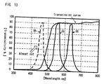
- the characteristic of blocking light on the short wavelength side having great energy more specifically, the characteristic of blocking light on the ultraviolet side from near blue is normally given to the sunglass lenses 101 and 106 as shown in a transmission characteristic graph of FIG. 13 .
- visible light that is external light is viewed as yellowish light while allowing light excluding blue light to remain.
- a color image is reproduced by combining light's three primary colors R, G, and B together, and therefore, if a structure in which the sunglass lenses are disposed closer to the eyeball than the display device is adopted as in FIG. 11 or FIG. 12 , B light will likewise be almost cut from light of images displayed on the display device as shown in the graph of FIG.
- the color image loses blue, and becomes yellowish as a whole.
- the sunglass lenses light on the blue side is originally cut, and therefore there is no difference in color (i.e., hue) after all, and the scenery becomes yellowish as a whole before the eyes of the user, and, as a result, the real image and the virtual image must be distinguished from each other only by the difference in brightness. Therefore, it becomes difficult to draw a distinction between the real image and the virtual image.
- the present invention has been made in consideration of the problems existing in the conventional technique, and it is an object of the present invention to provide a display unit that enables a user to easily distinguish a real image and a photographic image from each other regardless of a positional relationship between sunglass lenses and a display device.
- a display unit comprises an image data output device, an image projecting device that visualizes image data output from the image data output device and then projects the image data so as to be perceived by eyes of a user, a skeleton frame on which the image projecting device is mounted and that is set so that a nasal dorsum of the user and auricle bases of the user serve as parts that support the skeleton frame and sunglass lenses that have a predetermined transmission characteristic, the sunglass lenses being disposed directly or indirectly on the skeleton frame and being disposed in front of eyeballs of the user, respectively, in which the sunglass lenses are set so that a transmissivity of visible light in a predetermined wavelength region is peculiarly low and so that transmissivities of visible light in wavelength regions other than the visible light in the predetermined wavelength region are peculiarly high, and in which the coloring of image light visualized by the image projecting device is formed by light differing in color from the visible light having peculiarly high transmissivities in the sunglass lenses
- a display unit comprises an image pickup device, an image projecting device that visualizes image data output from the image pickup device and then projects a visualized image onto eyes of a user so as to be perceived by the user, a skeleton frame on which the image projecting device is mounted and that is set so that a nasal dorsum of the user and auricle bases of the user serve as parts that support the skeleton frame, and sunglass lenses that have a predetermined transmission characteristic, the sunglass lenses being disposed directly or indirectly on the skeleton frame and being disposed in front of eyeballs of the user, respectively; in which the sunglass lenses are set so that a transmissivity of visible light in a predetermined wavelength region is peculiarly low and so that transmissivities of visible light in wavelength regions other than the visible light in the predetermined wavelength region are peculiarly high, and in which the coloring of image light visualized by the image projecting device is formed by light differing in color from the visible light having peculiarly high transmissivities in the sunglass lenses.
- the image projecting device allows the eyes of a user to perceive an image visualized based on image data output from the image data output device.
- image light has a hue differing from that of a real image formed by external light that passes through the sunglass lenses and then reaches the eyeballs of the user, in other words, the color of image light and the color of a real image are different from each other, and therefore a clear distinction can be drawn between a photographic image and a real image, and the user can recognize the visualized image as an image differing from the real image without confusing the two images. For example, if only blue of visible light is cut in a lens (i.e., a sunglass lens), external light that passes through the lens will become yellow by light in remaining wavelength regions. In this case, colors other than yellow can be used as the color of photographic image light.
- the sunglass lenses are set so that a transmissivity of visible light in a predetermined wavelength region is peculiarly low
- a transmissivity of visible light in a predetermined wavelength region is peculiarly low
- the transmissivity is not necessarily limited to the fact that 100% of the visible light in the predetermined wavelength region is cut.
- either the reflecting action of light or the absorbing action of light may be used when light passing through the lens is cut.
- visible light in a predetermined wavelength region denotes visible light having a predetermined continuous width.
- the definition "the sunglass lenses are set so that transmissivities of visible light in wavelength regions other than the visible light in the predetermined wavelength region are peculiarly high” specifies a relative transmissivity with respect to the fact that a transmissivity of visible light in a predetermined wavelength region is peculiarly low, and does not necessarily specify a 100% transmissivity.
- a predetermined transmission characteristic to a sunglass lens it is generally performed to use, for example, colored glass that contains pigments showing an absorptive characteristic and a transmissive characteristic with respect to a predetermined wavelength region.
- an interference filter may also be used to reflect light having a specific wavelength.
- the interference filter is a filter that selects only light having a specific wavelength from an optical spectrum, and is a multilayer structure formed by piling arbitrary dielectric thin films or arbitrary metallic thin films in an arbitrary order so as to give a desired transmission characteristic thereto.
- the sunglass lens may be used also as a corrective lens. This lens is not necessarily required to be designed so that a correction degree is set for near-sightedness or astigmatism.
- the image projecting device examples include a transmissive display device that has an image projection monitor displaying an image supplied from the image data output device, more specifically, a transmissive display device that has a transparent board that visualizes data based on, for example, image data output from the image data output device and then guides the resulting image light to a reflection light element and a non-transmissive display device that has an image projection monitor displaying an image supplied from the image data output device.
- the term "reflection light element” mentioned here denotes, in the transparent board, an element that has a surface intersecting with a line extending in a direction in which the eyes of the user are looking, and an element that has a surface through which external light passes and onto which image light reflected and guided in the transparent board is projected.
- the reflection light element examples include a hologramelement and a half mirror.
- a retina scanning display in which a retina of the user is directly two-dimensionally scanned with coherent visible light, such as laser light, so as to recognize the visible light as an image without using the reflection light element can be used as a non-transmissive display device.
- the sunglass lens may be disposed before the transparent board (i.e., on the object side) or behind the transparent board (i.e., on the eyeball side).
- a photographic image i.e., virtual image
- a real image are mingled with each other even if any positional relationships are formed between the sunglass lens and the transparent board, and therefore the two images must be viewed with rays of light having mutually different wavelengths.
- the present invention is required to be applied when the sunglass lens is disposed behind the monitor.
- the image data output device may be an image pickup device.
- this denotes that a case in which image data excluding the image data obtained by actually performing photography is viewed is included.
- a color image is composed of the three primary colors RGB, the use of only one of these three colors makes it possible to produce a hue that can be easily distinguished from a real image.
- the maximum sensitive wavelength of humans is about 560 nm in a bright scene, and is about 500 nm in a dark scene, and hence resides in a wavelength region corresponding exactly to green. Therefore, images can be more easily recognized by using green as an image color.
- the image light is obtained by projecting an image taken by the image pickup device while using light of any one of the three primary colors RGB.
- a display unit according to an embodiment of the present invention will be hereinafter described with reference to the drawings.
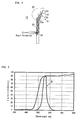
- the display unit for visual assistance (hereinafter, referred to simply as "display unit") 11 is composed of a transmissive display device 13 mounted on a skeleton frame 12 and corrective lenses 14.
- the skeleton frame 12 is composed of a main frame 15 and a pair of temples 17 connected to both ends of the main frame by means of hinges 16, respectively.
- a bracket 18 is attached to an inner surface of the center of the main frame 15.
- the transmissive display device 13 is composed of a camera 20 serving as an image pickup device, an image projecting part 21, and a transparent board 22 serving as an image projection monitor.
- the camera 20 is detachably attached to a part near the left end of the main frame 15.
- the image projecting part 21 is attached to the right upper end of the transparent board 22 in this embodiment, the image projecting part 21 may be attached to the left upper end of the transparent board 22 or to the right and left upper ends of the transparent board 22.
- the camera 20 and the image projecting part 21 are connected together by means of a cable 23.
- a power source for the camera 20 and the image projecting part 21 is not shown in the figures in this embodiment.
- an optical system of the camera 20 includes an RGB division optical circuit 25 composed of a beam splitter and a prism, three condensing lenses 26 disposed in accordance with each of the RGB lights behind the RGB division optical circuit 25, and image pickup tubes 27.
- the image pickup tubes 27 are connected to amplifiers 28 and to a control circuit 29 respectively.
- a photographic image is divided into three primary colors RGB in the RGB division optical circuit 25, and the resulting colors are guided to the image pickup tubes 27, and are converted into signals, respectively.
- Each of the RGB images converted into signals by the image pickup tubes 27 is processed by the amplifier 28 and the control circuit 29, and is output to the image projecting part 21 according to a predetermined signal system.
- the image projecting part 21 is composed of a light emitting diode (LED) 31 contained in a housing 30, a condensing lens 32, and a liquid crystal display (LCD) 33.
- the LED 31 is a green light emitting diode that emits wholly green light. Therefore, image data divided into three primary colors RGB is projected in a green color.
- Image data output from the camera 20 through the cable 23 is projected from the LED 31 onto the condensing lens 32 in the image projecting part 21, is then modulated by the LCD 33, and is admitted into the transparent board 22 through a corrective prism 22a disposed on the upper part of the transparent board 22 in the form of an image beam of light.
- the transparent board 22 totally reflects the image beam of light while serving as a total reflection prism.
- the image beam of light is guided to the hologram element 34 disposed in the transparent board 22 while being reflected therein, is then diffracted, and is admitted into the pupil.
- a user can view a virtual image of a scene displayed on the LCD 33.
- FIG. 5 is a graph showing transmission characteristics of the lens 14 according to this embodiment in a state of being overlapped with G light of the hologram element 34.
- the lens 14 is used also as a sunglass lens. Therefore, the lens 14 cuts blue-based light of visible light that is external light, and therefore a real image viewed by passing through the lens 14 has a yellowish hue (tone).
- a virtual image by means of G light is displayed on the hologram element 34 of the transparent board 22.
- a green virtual image V is viewed in a state of being overlapped with a yellowish real image RL passing through the lens 14 in a range smaller than the range of the yellowish real image RL as shown in, for example, FIG. 6 .
- the present invention may be modified and embodied as follows.
- a case in which an operation, such as a surgical operation, is performed while confirming a manual or a simulation screen can be conceived when an inexperienced or knowledge-poor operator performs the operation.
Landscapes
- Physics & Mathematics (AREA)
- General Physics & Mathematics (AREA)
- Optics & Photonics (AREA)
Priority Applications (1)
| Application Number | Priority Date | Filing Date | Title |
|---|---|---|---|
| EP10164105A EP2390708A1 (de) | 2010-05-27 | 2010-05-27 | Am Kopf angebrachte Anzeige |
Applications Claiming Priority (1)
| Application Number | Priority Date | Filing Date | Title |
|---|---|---|---|
| EP10164105A EP2390708A1 (de) | 2010-05-27 | 2010-05-27 | Am Kopf angebrachte Anzeige |
Publications (1)
| Publication Number | Publication Date |
|---|---|
| EP2390708A1 true EP2390708A1 (de) | 2011-11-30 |
Family
ID=42651347
Family Applications (1)
| Application Number | Title | Priority Date | Filing Date |
|---|---|---|---|
| EP10164105A Withdrawn EP2390708A1 (de) | 2010-05-27 | 2010-05-27 | Am Kopf angebrachte Anzeige |
Country Status (1)
| Country | Link |
|---|---|
| EP (1) | EP2390708A1 (de) |
Citations (6)
| Publication number | Priority date | Publication date | Assignee | Title |
|---|---|---|---|---|
| WO1996001440A1 (en) * | 1994-07-01 | 1996-01-18 | B.V. Optische Industrie 'de Oude Delft' | Display system for superposing three images for obtaining a mixed image |
| JP2006085011A (ja) | 2004-09-17 | 2006-03-30 | Konica Minolta Photo Imaging Inc | 映像表示装置 |
| JP2006098827A (ja) | 2004-09-30 | 2006-04-13 | Konica Minolta Photo Imaging Inc | 透過式映像表示装置 |
| EP1748305A1 (de) * | 2004-05-17 | 2007-01-31 | Nikon Corporation | Optisches element, optisches kombinierersystem und bildanzeigeeinheit |
| US20070279755A1 (en) * | 2006-06-01 | 2007-12-06 | 3M Innovative Properties Company | Head-Up Display System |
| US20090174946A1 (en) * | 2008-01-07 | 2009-07-09 | Roni Raviv | Customizable head mounted display |
-
2010
- 2010-05-27 EP EP10164105A patent/EP2390708A1/de not_active Withdrawn
Patent Citations (6)
| Publication number | Priority date | Publication date | Assignee | Title |
|---|---|---|---|---|
| WO1996001440A1 (en) * | 1994-07-01 | 1996-01-18 | B.V. Optische Industrie 'de Oude Delft' | Display system for superposing three images for obtaining a mixed image |
| EP1748305A1 (de) * | 2004-05-17 | 2007-01-31 | Nikon Corporation | Optisches element, optisches kombinierersystem und bildanzeigeeinheit |
| JP2006085011A (ja) | 2004-09-17 | 2006-03-30 | Konica Minolta Photo Imaging Inc | 映像表示装置 |
| JP2006098827A (ja) | 2004-09-30 | 2006-04-13 | Konica Minolta Photo Imaging Inc | 透過式映像表示装置 |
| US20070279755A1 (en) * | 2006-06-01 | 2007-12-06 | 3M Innovative Properties Company | Head-Up Display System |
| US20090174946A1 (en) * | 2008-01-07 | 2009-07-09 | Roni Raviv | Customizable head mounted display |
Similar Documents
| Publication | Publication Date | Title |
|---|---|---|
| US8182084B2 (en) | Display unit | |
| JP4600290B2 (ja) | 視覚補助表示装置 | |
| US9269193B2 (en) | Head-mount type display device | |
| US8398242B2 (en) | Display apparatus | |
| JP4411547B2 (ja) | 画像表示装置 | |
| JP6089705B2 (ja) | 表示装置、および、表示装置の制御方法 | |
| US20210035533A1 (en) | Display device and display method | |
| CN109725416B (zh) | 眼球追踪光学系统、头戴式设备及成像方法 | |
| JPH08160344A (ja) | 頭部装着式映像表示装置 | |
| KR20220129542A (ko) | 표시 장치 | |
| JP2008058461A (ja) | 映像表示装置、及び頭部装着式映像表示装置 | |
| JP5467287B2 (ja) | ディスプレイユニット | |
| JP2005284007A (ja) | 透過式映像表示装置 | |
| JP2008287049A (ja) | 映像表示装置およびヘッドマウントディスプレイ | |
| CA2705633C (en) | Display unit | |
| JP2010128246A5 (de) | ||
| EP2390708A1 (de) | Am Kopf angebrachte Anzeige | |
| JP7809207B2 (ja) | 一体型レンズディスプレイ用のレンズ着色 | |
| JP2003015075A (ja) | 電子眼鏡および眼鏡取付型表示装置 | |
| JP2002107654A (ja) | 映像表示装置 | |
| JP7011295B2 (ja) | 色覚支援装置 | |
| JP2010256657A (ja) | 透過型ディスプレイ装置及びディスプレイユニット | |
| WO2019077975A1 (ja) | 映像表示装置と光学シースルーディスプレイ | |
| JP2006098827A (ja) | 透過式映像表示装置 | |
| JP3333165B2 (ja) | 頭部装着型映像表示装置 |
Legal Events
| Date | Code | Title | Description |
|---|---|---|---|
| AK | Designated contracting states |
Kind code of ref document: A1 Designated state(s): AL AT BE BG CH CY CZ DE DK EE ES FI FR GB GR HR HU IE IS IT LI LT LU LV MC MK MT NL NO PL PT RO SE SI SK SM TR |
|
| AX | Request for extension of the european patent |
Extension state: BA ME RS |
|
| PUAI | Public reference made under article 153(3) epc to a published international application that has entered the european phase |
Free format text: ORIGINAL CODE: 0009012 |
|
| STAA | Information on the status of an ep patent application or granted ep patent |
Free format text: STATUS: THE APPLICATION IS DEEMED TO BE WITHDRAWN |
|
| 18D | Application deemed to be withdrawn |
Effective date: 20120531 |