EP2390639A2 - Laser shock peening measurement system and method - Google Patents
Laser shock peening measurement system and method Download PDFInfo
- Publication number
- EP2390639A2 EP2390639A2 EP11167157A EP11167157A EP2390639A2 EP 2390639 A2 EP2390639 A2 EP 2390639A2 EP 11167157 A EP11167157 A EP 11167157A EP 11167157 A EP11167157 A EP 11167157A EP 2390639 A2 EP2390639 A2 EP 2390639A2
- Authority
- EP
- European Patent Office
- Prior art keywords
- energy
- acoustic
- container
- electrically conducting
- piston
- Prior art date
- Legal status (The legal status is an assumption and is not a legal conclusion. Google has not performed a legal analysis and makes no representation as to the accuracy of the status listed.)
- Granted
Links
Images

Classifications
-
- G—PHYSICS
- G01—MEASURING; TESTING
- G01S—RADIO DIRECTION-FINDING; RADIO NAVIGATION; DETERMINING DISTANCE OR VELOCITY BY USE OF RADIO WAVES; LOCATING OR PRESENCE-DETECTING BY USE OF THE REFLECTION OR RERADIATION OF RADIO WAVES; ANALOGOUS ARRANGEMENTS USING OTHER WAVES
- G01S7/00—Details of systems according to groups G01S13/00, G01S15/00, G01S17/00
- G01S7/52—Details of systems according to groups G01S13/00, G01S15/00, G01S17/00 of systems according to group G01S15/00
- G01S7/521—Constructional features
-
- C—CHEMISTRY; METALLURGY
- C21—METALLURGY OF IRON
- C21D—MODIFYING THE PHYSICAL STRUCTURE OF FERROUS METALS; GENERAL DEVICES FOR HEAT TREATMENT OF FERROUS OR NON-FERROUS METALS OR ALLOYS; MAKING METAL MALLEABLE, e.g. BY DECARBURISATION OR TEMPERING
- C21D10/00—Modifying the physical properties by methods other than heat treatment or deformation
- C21D10/005—Modifying the physical properties by methods other than heat treatment or deformation by laser shock processing
-
- B—PERFORMING OPERATIONS; TRANSPORTING
- B23—MACHINE TOOLS; METAL-WORKING NOT OTHERWISE PROVIDED FOR
- B23K—SOLDERING OR UNSOLDERING; WELDING; CLADDING OR PLATING BY SOLDERING OR WELDING; CUTTING BY APPLYING HEAT LOCALLY, e.g. FLAME CUTTING; WORKING BY LASER BEAM
- B23K26/00—Working by laser beam, e.g. welding, cutting or boring
- B23K26/02—Positioning or observing the workpiece, e.g. with respect to the point of impact; Aligning, aiming or focusing the laser beam
- B23K26/03—Observing, e.g. monitoring, the workpiece
-
- B—PERFORMING OPERATIONS; TRANSPORTING
- B23—MACHINE TOOLS; METAL-WORKING NOT OTHERWISE PROVIDED FOR
- B23K—SOLDERING OR UNSOLDERING; WELDING; CLADDING OR PLATING BY SOLDERING OR WELDING; CUTTING BY APPLYING HEAT LOCALLY, e.g. FLAME CUTTING; WORKING BY LASER BEAM
- B23K26/00—Working by laser beam, e.g. welding, cutting or boring
- B23K26/352—Working by laser beam, e.g. welding, cutting or boring for surface treatment
- B23K26/356—Working by laser beam, e.g. welding, cutting or boring for surface treatment by shock processing
-
- G—PHYSICS
- G01—MEASURING; TESTING
- G01K—MEASURING TEMPERATURE; MEASURING QUANTITY OF HEAT; THERMALLY-SENSITIVE ELEMENTS NOT OTHERWISE PROVIDED FOR
- G01K17/00—Measuring quantity of heat
- G01K17/003—Measuring quantity of heat for measuring the power of light beams, e.g. laser beams
Definitions
- the subject matter disclosed herein relates to treating metal and, in particular, to monitoring laser metal treatments.
- Laser peening or laser shock peening (LSP) is a process of inducing beneficial residual compressive stresses into a material (usually metal) by using a powerful laser.
- a material being processed shall be referred to as a "treated material.”
- An ablative coating usually black tape or paint, is applied to the treated material to absorb the energy from a laser. Short energy pulses from the laser are then focused to explode the ablative coating, producing a shock wave. The process may be repeated in multiple locations.
- a translucent layer usually consisting of water, is required over the coating and acts as a tamp, directing the shock wave into the treated material.
- a piezoelectric sensor is normally used for real time (on-line) monitoring of LSP processing.
- the piezoelectric sensor converts the stress (acoustic) waves created by LSP into an electric signal proportional to the strength of the wave. The electric signal may then be used to monitor the LSP process.
- the piezoelectric sensor however, is often destroyed because it is in direct contact with the treated material. The one-use destruction of these gauges requires the use of multiple gauges for wherever multiple laser pulses are needed.
- a laser shock peening (LSP) measurement device for measuring energy provided to a treated material during an LSP process.
- the device of this embodiment includes an energy converter configured to receive acoustic energy from the treated material and to convert the acoustic energy to thermal energy.
- the device of this embodiment also includes an energy measurement device coupled to the energy converter that produces an electrical output based on the thermal energy proportional to the acoustic energy.
- a method of monitoring laser shock peening of a material includes forming an ablative layer on the material, directing the laser beam at the ablative layer to produce an acoustic wave in the material, converting the acoustic wave in the material to thermal energy external to the material and measuring the thermal energy.
- a turbine is provided.
- the turbine of this embodiment is prepared by a process comprising: forming an ablative layer on a blade of the turbine; directing the laser beam at the ablative layer to produce an acoustic wave in the material; converting the acoustic wave in the material to thermal energy external to the material; and measuring the thermal energy.
- utilizing piezoelectric sensors in LSP processing requires the use of multiple sensors because the sensors can be destroyed by one use.
- monitoring the LSP process by measuring the acoustic waves directly results in operator discomfort due to the high sound levels produced. Indeed, some LSP processes create sound levels ranging from 100 to 140 dB.
- Embodiments of the present invention may convert the acoustic waves to another form of energy to reduce the sound level associated with LSP processing.
- conversion of the waves to another form may increase the lifetime of sensors used to monitor LSP processes.
- Embodiments of the present invention may allow for sensors utilized in online LSP monitoring to be reused because they are not in direct contact with material being processed. In one embodiment, this may be accomplished by modifying the measured energy from acoustic to thermal through the use of magnetic fields and an electrically conductive medium.
- the acoustic wave is transmitted away from the treated material by an acoustic coupler having the same or similar acoustic impedance as the treated material. This acoustic wave is then converted to heat. The conversion may occur, for example, in an electrically conductive medium.
- coils that generate a magnetic field may surround the medium.
- the electrically conductive medium and the coils may be enclosed inside a housing or container made of a material having a different acoustic impedance than the treated material in order to prevent acoustic energy loss due to transmission to the outside environment.
- the temperature rise of the medium inside the container heats a thermally conductivity plate that contacts the container. The resultant temperature increase of the thermal plate is converted into an electric voltage by a sensor.
- the thermally conductive plate may be omitted and temperature changes in the medium may be directly measured using techniques known in the art. For instance, temperature changes may be measured using an IR detector or a radiometer.
- FIG. 1 shows an LSP system 100 according to one embodiment of the present invention.
- the LSP system 100 includes a laser 102 and a treated material 104.
- the treated material 104 is a metal.
- the treated material may be metal the forms the blades of turbine. Accordingly, the system 100 may be used to create turbines.
- the system 100 may be utilized in other contexts as well.
- the treated material 104 may include an ablative layer 106 affixed to a first side 105 thereof.
- the ablative layer 106 may be formed of a black tape or paint and is applied to absorb the energy imparted by the laser 102.
- On a second side 107 the treated material 104 may include an acoustic coupler 108 in intimate contact therewith.
- the acoustic coupler 108 may have the same or substantially the same acoustic impedance as the treated material 104.
- the laser 102 is directed at the ablative material 106. Short energy pulses are then focused to explode the ablative material 106, producing a shock waves 110.
- the shock waves 110 may have detrimental effects if allowed to reflect inside the treated material 104. Reflected waves are indicated by reference numeral 112.
- the reflected waves 112 can propagate cracks due to their tensile nature and reduce the life of the treated material 104.
- placing the acoustic coupler 108 in intimate contact with the treated material 104 may reduce or eliminate reflected waves 112.
- use of an acoustic coupler 108 transmits the shock waves out of the treated material 104.
- the waves transmitted out of the treated material 104 may be used for online monitoring of LSP processes.
- One embodiment of the present invention includes an energy converter 114 coupled to the acoustic coupler 108.
- the energy converter 114 may convert the acoustic shock waves 110 to another form of energy.
- the energy converter 114 converts the acoustic waves into thermal energy.
- An energy measurement device 116 may measure the converted energy output by the energy converter 114.
- the energy measurement device 116 may include a thermally conductivity plate that contacts the energy converter 114. The resultant temperature increase of the thermal plate is converted into an electric signal (current or voltage) by a sensor forming part of the energy measurement device 116.
- Such an energy measurement device 116 LSP sensor
- the energy measurement device 116 may measure temperature changes in the electrically conductive material directly. For instance, an energy measurement device 116 implemented as an IR detector or a radiometer may directly measure temperature changes.
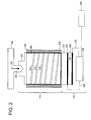
- FIG. 2 shows a more detailed example of an energy converter 114 according to one embodiment of the present invention.
- the energy converter 114 is coupled between an acoustic coupler 108 and an energy measurement device 116.
- the energy converter 114 converts acoustic energy (waves) to thermal energy in one embodiment.
- the acoustic coupler 108 may include a plunger 202.
- the plunger 202 directs and transmits the shock wave 110 to the energy converter 114.
- the plunger 202 directs and transmits the shock waves 110 to a piston 204 of the energy converter 114.
- the electric conductor When an electric conductor is made to move in a magnetic field, an electromotive force is produced.
- the electric conductor can be replaced by any electrically conducting medium (such as a fluid or a gas) that is a good conductor of electricity.
- the medium can be made electrically conducting by ionization or by other means known in the art.
- the energy converter 114 includes an electrically conducting medium 206 disposed within a container 208.
- the electrically conducting medium 206 may be set into motion by shock waves 110 being transmitted to piston 204.
- the shock waves 110 generated during LSP may cause motion in the electrically conducting medium 206 after traversing through the treated material and the acoustic coupler 108.
- the acoustic coupler 108 is formed of a material with the same acoustic impedance as the treated material, the transmission ratio may be increased. Forming the acoustic coupler 108 such that it includes the plunger 202 may focus the shock wave.
- the acoustic coupler 108 generally, and plunger 202 in particular, may be coupled to piston 204.
- the piston 204 may be made of acoustically similar material to the acoustic coupler 108.
- the acoustic waves from the piston 204 then traverse through the electrically conducting medium 206 within the container 208.
- the container 208 may be made of a material having a dissimilar acoustic impedance from the treated material 104 so that there is no loss of acoustic energy inside the container 208 due to transmission of the waves to the outside.
- the container 208 may include a casing 210 disposed on its outer walls.
- the casing 210 may be made of material having a dissimilar acoustic impedance to prevent any acoustic transmissions and reflect all the energy inside the container 208.
- a magnetic field is generated in the medium 206 inside the container 208 by passing a suitable current through coils 212 surrounding the medium 206.
- coils 212 are disposed within the container 208. In another embodiment, the coils 212 surround the container 208.
- the magnetic field can also be generated without the coils by the use of permanent magnets or electromagnets.
- the electrically conducting medium 206 is set into motion by the electromotive force of a magnetic field produced by the coils 212.
- the magnetic field is the result of applying a current via leads 230 to the coils.
- the flux produced by the magnetic field is aligned so that it is in a different direction than the shock wave 110 travels.
- the flux is aligned in an opposite direction than the shock wave 110 travels.
- the energy of the shock wave 110 gets reduced as it gets converted to electromotive force.
- eddy currents are generated in the medium 206 due to the electromotive force and, thus, the shock wave 110 gets converted into thermal energy due to its electromotive force acting in opposition to the magnetic flux generated by the coils 212.
- the container 208 may be formed of a high-temperature material capable of withstanding the high temperatures generated.
- the container 208 may, as described above, may be made of material that has different acoustic impedance than the acoustic coupler 108 so that any acoustic waves that have a tendency to escape the container 208 are not allowed to do so and are contained therein.
- the electrically conducting medium 206 is an electrically conducting fluid, an organic/inorganic fluid, or a gas, that has an acoustic impedance similar to or the same as the acoustic impedance of the acoustic coupler 108.
- the impedance match can be made when the fluid used has same Bulk modulus/density values.
- the energy converter 108 may be coupled to energy measurement device 116.
- the energy measurement device 116 may be a temperature sensor in one embodiment.
- the energy measurement device 116 may include a first conductive plate 220 in thermal contact with the container 208.
- the first conductive plate 220 directly contacts the container 208.
- the first conductive plate 220 is made of a material having a high thermal conductivity. The temperature increase in the electrically conducting medium 206 (and container 208) is thus transferred through the first conducting plate 220.
- the first conductive plate contacts a pyroelectric layer 222.
- the pyroelectric layer 222 may be coated on both sides with suitable electrically conductive layers 224. A temperature increase in the pyroelectric layer 222 is converted into a voltage between the electrically conductive layers 224. The combination of the pyroelectric layer 222 and the electrically conductive layers 224, therefore, form a pyroelectric transducer.
- conductive wires 226 are connected to the electrically conductive layers 224 and the voltage difference may be measure by a voltage meter 228.
- the voltage output is displayed on a screen and may be used as a direct indication of any water or paint malfunction. Any process inadequacies translate to a reduction in the shock pressure produced which results in a lower temperature rise in the electrically conducting fluid.
- the energy temperature measurement device 116 may be connected to a comparator 230, which compares the measured temperature value to predetermined limits set for process parameters. For example, if the thickness of the ablative paint is not optimal or the water flow rate is not optimal, the shock wave intensity produced is much less. This results in a non-optimal laser shock peening process and lower depth of residual compressive stresses.
- the comparator 230 compares the deviation of the signal from the optimal process parameters and sends a defect alarm if any deviation is detected. The comparator can thus detect the exact location and send a signal to carry out the laser shock processing again with revised set of process parameters (like water flow rate, paint thickness etc.), to get the desired peening effect. Thus, real-time monitoring of the process variables can be ensured.
- thermal energy can be directly measured using techniques known in the art like IR, radiometer etc instead of converting the temperature to an electric output through a pyroelectric transducer.
Landscapes
- Engineering & Computer Science (AREA)
- Physics & Mathematics (AREA)
- Optics & Photonics (AREA)
- Chemical & Material Sciences (AREA)
- Mechanical Engineering (AREA)
- Plasma & Fusion (AREA)
- General Physics & Mathematics (AREA)
- Crystallography & Structural Chemistry (AREA)
- Metallurgy (AREA)
- Organic Chemistry (AREA)
- Materials Engineering (AREA)
- Combustion & Propulsion (AREA)
- Thermal Sciences (AREA)
- Computer Networks & Wireless Communication (AREA)
- Radar, Positioning & Navigation (AREA)
- Remote Sensing (AREA)
- Investigating Or Analyzing Materials By The Use Of Ultrasonic Waves (AREA)
- Laser Beam Processing (AREA)
- Measurement Of Mechanical Vibrations Or Ultrasonic Waves (AREA)
- Length Measuring Devices Characterised By Use Of Acoustic Means (AREA)
Abstract
Description
- The subject matter disclosed herein relates to treating metal and, in particular, to monitoring laser metal treatments.
- Laser peening, or laser shock peening (LSP), is a process of inducing beneficial residual compressive stresses into a material (usually metal) by using a powerful laser. As used herein, a material being processed shall be referred to as a "treated material." An ablative coating, usually black tape or paint, is applied to the treated material to absorb the energy from a laser. Short energy pulses from the laser are then focused to explode the ablative coating, producing a shock wave. The process may be repeated in multiple locations. A translucent layer, usually consisting of water, is required over the coating and acts as a tamp, directing the shock wave into the treated material.
- A piezoelectric sensor is normally used for real time (on-line) monitoring of LSP processing. The piezoelectric sensor converts the stress (acoustic) waves created by LSP into an electric signal proportional to the strength of the wave. The electric signal may then be used to monitor the LSP process. The piezoelectric sensor, however, is often destroyed because it is in direct contact with the treated material. The one-use destruction of these gauges requires the use of multiple gauges for wherever multiple laser pulses are needed.
- According to one aspect of the invention, a laser shock peening (LSP) measurement device for measuring energy provided to a treated material during an LSP process is provided. The device of this embodiment includes an energy converter configured to receive acoustic energy from the treated material and to convert the acoustic energy to thermal energy. The device of this embodiment also includes an energy measurement device coupled to the energy converter that produces an electrical output based on the thermal energy proportional to the acoustic energy.
- According to another aspect of the invention, a method of monitoring laser shock peening of a material is provided. The method includes forming an ablative layer on the material, directing the laser beam at the ablative layer to produce an acoustic wave in the material, converting the acoustic wave in the material to thermal energy external to the material and measuring the thermal energy.
- According to yet another aspect of the invention, a turbine is provided. The turbine of this embodiment is prepared by a process comprising: forming an ablative layer on a blade of the turbine; directing the laser beam at the ablative layer to produce an acoustic wave in the material; converting the acoustic wave in the material to thermal energy external to the material; and measuring the thermal energy.
- These and other advantages and features will become more apparent from the following description taken in conjunction with the drawings.
- The subject matter, which is regarded as the invention, is particularly pointed out and distinctly claimed in the claims at the conclusion of the specification. The foregoing and other features, and advantages of the invention are apparent from the following detailed description taken in conjunction with the accompanying drawings in which:
-
FIG. 1 shows an LSP system according to one embodiment of the present invention; and -
FIG. 2 shows a detailed example of an energy converter according to one embodiment of the present invention. - The detailed description explains embodiments of the invention, together with advantages and features, by way of example with reference to the drawings.
- As described above, utilizing piezoelectric sensors in LSP processing requires the use of multiple sensors because the sensors can be destroyed by one use. In addition, monitoring the LSP process by measuring the acoustic waves directly results in operator discomfort due to the high sound levels produced. Indeed, some LSP processes create sound levels ranging from 100 to 140 dB.
- Embodiments of the present invention may convert the acoustic waves to another form of energy to reduce the sound level associated with LSP processing. In addition, conversion of the waves to another form may increase the lifetime of sensors used to monitor LSP processes.
- Embodiments of the present invention may allow for sensors utilized in online LSP monitoring to be reused because they are not in direct contact with material being processed. In one embodiment, this may be accomplished by modifying the measured energy from acoustic to thermal through the use of magnetic fields and an electrically conductive medium. In particular, the acoustic wave is transmitted away from the treated material by an acoustic coupler having the same or similar acoustic impedance as the treated material. This acoustic wave is then converted to heat. The conversion may occur, for example, in an electrically conductive medium. In one embodiment, coils that generate a magnetic field may surround the medium.
- The electrically conductive medium and the coils may be enclosed inside a housing or container made of a material having a different acoustic impedance than the treated material in order to prevent acoustic energy loss due to transmission to the outside environment. In one embodiment, the temperature rise of the medium inside the container heats a thermally conductivity plate that contacts the container. The resultant temperature increase of the thermal plate is converted into an electric voltage by a sensor.
- In an alternative embodiment, the thermally conductive plate may be omitted and temperature changes in the medium may be directly measured using techniques known in the art. For instance, temperature changes may be measured using an IR detector or a radiometer.
-
FIG. 1 shows anLSP system 100 according to one embodiment of the present invention. TheLSP system 100 includes alaser 102 and a treatedmaterial 104. In one embodiment, the treatedmaterial 104 is a metal. In a specific embodiment, the treated material may be metal the forms the blades of turbine. Accordingly, thesystem 100 may be used to create turbines. Of course, thesystem 100 may be utilized in other contexts as well. - The treated
material 104 may include anablative layer 106 affixed to a first side 105 thereof. Theablative layer 106 may be formed of a black tape or paint and is applied to absorb the energy imparted by thelaser 102. On a second side 107 the treatedmaterial 104 may include anacoustic coupler 108 in intimate contact therewith. Theacoustic coupler 108 may have the same or substantially the same acoustic impedance as the treatedmaterial 104. - In operation, the
laser 102 is directed at theablative material 106. Short energy pulses are then focused to explode theablative material 106, producing ashock waves 110. Theshock waves 110 may have detrimental effects if allowed to reflect inside the treatedmaterial 104. Reflected waves are indicated byreference numeral 112. Thereflected waves 112 can propagate cracks due to their tensile nature and reduce the life of the treatedmaterial 104. - It has been discovered that placing the
acoustic coupler 108 in intimate contact with the treatedmaterial 104 may reduce or eliminatereflected waves 112. In particular, use of anacoustic coupler 108 transmits the shock waves out of the treatedmaterial 104. The waves transmitted out of the treatedmaterial 104 may be used for online monitoring of LSP processes. - One embodiment of the present invention includes an
energy converter 114 coupled to theacoustic coupler 108. Theenergy converter 114 may convert theacoustic shock waves 110 to another form of energy. In one embodiment, theenergy converter 114 converts the acoustic waves into thermal energy. - An
energy measurement device 116 may measure the converted energy output by theenergy converter 114. In one embodiment, theenergy measurement device 116 may include a thermally conductivity plate that contacts theenergy converter 114. The resultant temperature increase of the thermal plate is converted into an electric signal (current or voltage) by a sensor forming part of theenergy measurement device 116. Such an energy measurement device 116 (LSP sensor) may be utilized more than once because it is not destroyed by direct contact with a shock wave as in the prior art. In an alternative embodiment, theenergy measurement device 116 may measure temperature changes in the electrically conductive material directly. For instance, anenergy measurement device 116 implemented as an IR detector or a radiometer may directly measure temperature changes. -
FIG. 2 shows a more detailed example of anenergy converter 114 according to one embodiment of the present invention. Theenergy converter 114 is coupled between anacoustic coupler 108 and anenergy measurement device 116. Theenergy converter 114 converts acoustic energy (waves) to thermal energy in one embodiment. - The
acoustic coupler 108 may include aplunger 202. Theplunger 202 directs and transmits theshock wave 110 to theenergy converter 114. In particular, theplunger 202 directs and transmits theshock waves 110 to apiston 204 of theenergy converter 114. - When an electric conductor is made to move in a magnetic field, an electromotive force is produced. The electric conductor can be replaced by any electrically conducting medium (such as a fluid or a gas) that is a good conductor of electricity. The medium can be made electrically conducting by ionization or by other means known in the art.
- In one embodiment, the
energy converter 114 includes an electrically conducting medium 206 disposed within acontainer 208. The electrically conducting medium 206 may be set into motion byshock waves 110 being transmitted topiston 204. - In more detail, the
shock waves 110 generated during LSP may cause motion in the electrically conducting medium 206 after traversing through the treated material and theacoustic coupler 108. In the event theacoustic coupler 108 is formed of a material with the same acoustic impedance as the treated material, the transmission ratio may be increased. Forming theacoustic coupler 108 such that it includes theplunger 202 may focus the shock wave. - In one embodiment, the
acoustic coupler 108 generally, andplunger 202 in particular, may be coupled topiston 204. In one embodiment, thepiston 204 may be made of acoustically similar material to theacoustic coupler 108. The acoustic waves from thepiston 204 then traverse through the electrically conducting medium 206 within thecontainer 208. Thecontainer 208 may be made of a material having a dissimilar acoustic impedance from the treatedmaterial 104 so that there is no loss of acoustic energy inside thecontainer 208 due to transmission of the waves to the outside. In one embodiment, thecontainer 208 may include acasing 210 disposed on its outer walls. Thecasing 210 may be made of material having a dissimilar acoustic impedance to prevent any acoustic transmissions and reflect all the energy inside thecontainer 208. - In operation, a magnetic field is generated in the medium 206 inside the
container 208 by passing a suitable current throughcoils 212 surrounding the medium 206. In one embodiment, coils 212 are disposed within thecontainer 208. In another embodiment, thecoils 212 surround thecontainer 208. The magnetic field can also be generated without the coils by the use of permanent magnets or electromagnets. - The electrically conducting medium 206 is set into motion by the electromotive force of a magnetic field produced by the
coils 212. The magnetic field is the result of applying a current via leads 230 to the coils. In one embodiment, the flux produced by the magnetic field is aligned so that it is in a different direction than theshock wave 110 travels. In one embodiment, the flux is aligned in an opposite direction than theshock wave 110 travels. The energy of theshock wave 110 gets reduced as it gets converted to electromotive force. In particular, eddy currents are generated in the medium 206 due to the electromotive force and, thus, theshock wave 110 gets converted into thermal energy due to its electromotive force acting in opposition to the magnetic flux generated by thecoils 212. Thus, there is an increase in the temperature of the medium 206. This temperature rise is proportional to the strength of the shock waves and the magnetic flux generated by thecoils 212. - In one embodiment, the
container 208 may be formed of a high-temperature material capable of withstanding the high temperatures generated. Thecontainer 208 may, as described above, may be made of material that has different acoustic impedance than theacoustic coupler 108 so that any acoustic waves that have a tendency to escape thecontainer 208 are not allowed to do so and are contained therein. - In one embodiment, the electrically conducting medium 206 is an electrically conducting fluid, an organic/inorganic fluid, or a gas, that has an acoustic impedance similar to or the same as the acoustic impedance of the
acoustic coupler 108. The impedance match can be made when the fluid used has same Bulk modulus/density values. - The
energy converter 108 may be coupled toenergy measurement device 116. Theenergy measurement device 116 may be a temperature sensor in one embodiment. In such an embodiment, theenergy measurement device 116 may include a firstconductive plate 220 in thermal contact with thecontainer 208. In one embodiment, the firstconductive plate 220 directly contacts thecontainer 208. In one embodiment, the firstconductive plate 220 is made of a material having a high thermal conductivity. The temperature increase in the electrically conducting medium 206 (and container 208) is thus transferred through thefirst conducting plate 220. - In one embodiment, the first conductive plate contacts a
pyroelectric layer 222. Thepyroelectric layer 222 may be coated on both sides with suitable electricallyconductive layers 224. A temperature increase in thepyroelectric layer 222 is converted into a voltage between the electricallyconductive layers 224. The combination of thepyroelectric layer 222 and the electricallyconductive layers 224, therefore, form a pyroelectric transducer. - In one embodiment,
conductive wires 226 are connected to the electricallyconductive layers 224 and the voltage difference may be measure by avoltage meter 228. Of course, any means of determining the voltage difference (or a current created) due to the temperature change transmitted to thepyroelectric transducer 222 may be utilized. In one embodiment, the voltage output is displayed on a screen and may be used as a direct indication of any water or paint malfunction. Any process inadequacies translate to a reduction in the shock pressure produced which results in a lower temperature rise in the electrically conducting fluid. - In one embodiment, the energy
temperature measurement device 116 may be connected to acomparator 230, which compares the measured temperature value to predetermined limits set for process parameters. For example, if the thickness of the ablative paint is not optimal or the water flow rate is not optimal, the shock wave intensity produced is much less. This results in a non-optimal laser shock peening process and lower depth of residual compressive stresses. Thecomparator 230 compares the deviation of the signal from the optimal process parameters and sends a defect alarm if any deviation is detected. The comparator can thus detect the exact location and send a signal to carry out the laser shock processing again with revised set of process parameters (like water flow rate, paint thickness etc.), to get the desired peening effect. Thus, real-time monitoring of the process variables can be ensured. - Alternately the thermal energy can be directly measured using techniques known in the art like IR, radiometer etc instead of converting the temperature to an electric output through a pyroelectric transducer.
- While the invention has been described in detail in connection with only a limited number of embodiments, it should be readily understood that the invention is not limited to such disclosed embodiments. Rather, the invention can be modified to incorporate any number of variations, alterations, substitutions or equivalent arrangements not heretofore described, but which are commensurate with the spirit and scope of the invention. Additionally, while various embodiments of the invention have been described, it is to be understood that aspects of the invention may include only some of the described embodiments. Accordingly, the invention is not to be seen as limited by the foregoing description, but is only limited by the scope of the appended claims.
- For completeness, various aspects of the invention are now set out in the following numbered clauses:
- 1. A laser shock peening (LSP) measurement device for measuring energy provided to a treated material during an LSP process, the device comprising:
- an energy converter configured to receive acoustic energy from the treated material and to convert the acoustic energy to thermal energy; and
- an energy measurement device coupled to the energy converter that produces an electrical output based on the thermal energy proportional to the acoustic energy.
- 2. The device of clause 1, wherein the energy converter includes:
- a container having a first acoustic impedance;
- an electrically conducting medium within the container; and
- one or more coils disposed within the container.
- 3. The device of clause 2, wherein the energy converter further includes:
- a piston at a first end of the container, the piston having a second acoustic impedance different than the first acoustic impedance and contacting the electrically conducting medium.
- 4. The device of clause 3, further comprising:
- an acoustic coupler coupled between the piston and the treated material, the acoustic coupler having a third acoustic impedance.
- 5. The device of clause 4, wherein the third acoustic impedance is the same as the second acoustic impedance.
- 6. The device of clause 3, wherein the one or more coils receive an electric current and produce an electric flux in a first direction and wherein the piston moves in a second direction different than the first direction.
- 7. The device of clause 3, wherein the acoustic coupler includes a plunger and wherein the plunger is coupled to the piston.
- 8. The device of clause 1, wherein the energy measurement device includes a pyroelectric layer in thermal contact with the energy conversion device.
- 9. The device of clause 1, in combination with a laser.
- 10. The device of clause 1, further comprising:
- a comparator coupled to the energy measurement device that compares the electrical output to predetermined ranges to determine effectiveness of an LSP process.
- 11. A method of monitoring laser shock peening of a material, the method comprising:
- forming an ablative layer on the material;
- directing the laser beam at the ablative layer to produce an acoustic wave in the material;
- converting the acoustic wave in the material to thermal energy external to the material; and
- measuring the thermal energy.
- 12. The method of clause 11, wherein converting includes directing the acoustic wave to an electrically conducting material in a first direction.
- 13. The method of clause 12, wherein converting further includes creating an electric flux in the electrically conducting material in a second direction, the second direction being different than the first direction.
- 14. The method of clause 13, wherein the electrically conducting material is disposed within a container that includes one or more electric coils, wherein the electric flux is created when a current is applied to the electric coils.
- 15. The method of clause 12, wherein directing includes:
- attaching an acoustic coupler to the material.
- 16. The method of clause 15, wherein the acoustic coupler has an acoustic impedance that matches an acoustic impedance of the material.
Claims (15)
- A laser shock peening LSP (100) measurement device for measuring energy provided to a treated material during an LSP process, the device comprising:an energy converter (114) configured to receive acoustic energy from the treated material (104) and to convert the acoustic energy to thermal energy; andan energy measurement device (116) coupled to the energy converter that produces an electrical output based on the thermal energy proportional to the acoustic energy.
- The device of claim 1, wherein the energy converter includes:a container (208) having a first acoustic impedance;an electrically conducting medium (206) within the container; andone or more coils (212) disposed within the container.
- The device of claim 2, wherein the energy converter further includes:a piston (204) at a first end of the container, the piston having a second acoustic impedance different than the first acoustic impedance and contacting the electrically conducting medium.
- The device of claim 3, further comprising:an acoustic coupler (108) coupled between the piston and the treated material, the acoustic coupler having a third acoustic impedance.
- The device of claim 4, wherein the third acoustic impedance is the same as the second acoustic impedance.
- The device of claim 3, wherein the one or more coils receive an electric current and produce an electric flux in a first direction and wherein the piston moves in a second direction different than the first direction.
- The device of claim 3, wherein the acoustic coupler includes a plunger (202) and wherein the plunger is coupled to the piston.
- The device of claim 1, wherein the energy measurement device includes a pyroelectric layer in thermal contact with the energy conversion device.
- The device of claim 1, in combination with a laser.
- The device of claim 1, further comprising:a comparator coupled to the energy measurement device that compares the electrical output to predetermined ranges to determine effectiveness of an LSP process.
- A method of monitoring laser shock peening (100) of a material, the method comprising:forming an ablative layer (106) on the material;directing the laser beam at the ablative layer (106) to produce an acoustic wave in the material;converting the acoustic wave in the material to thermal energy external to the material; andmeasuring the thermal energy.
- The method of claim 11, wherein converting includes directing the acoustic wave to an electrically conducting material in a first direction.
- The method of claim 12, wherein converting further includes creating an electric flux in the electrically conducting material in a second direction, the second direction being different than the first direction.
- The method of claim 13, wherein the electrically conducting material is disposed within a container that includes one or more electric coils, wherein the electric flux is created when a current is applied to the electric coils.
- The method of claim 12, wherein directing includes:attaching an acoustic coupler to the material.
Applications Claiming Priority (1)
| Application Number | Priority Date | Filing Date | Title |
|---|---|---|---|
| US12/786,031 US8520470B2 (en) | 2010-05-24 | 2010-05-24 | Laser shock peening measurement system and method |
Publications (3)
| Publication Number | Publication Date |
|---|---|
| EP2390639A2 true EP2390639A2 (en) | 2011-11-30 |
| EP2390639A3 EP2390639A3 (en) | 2016-07-27 |
| EP2390639B1 EP2390639B1 (en) | 2017-08-30 |
Family
ID=44597247
Family Applications (1)
| Application Number | Title | Priority Date | Filing Date |
|---|---|---|---|
| EP11167157.4A Active EP2390639B1 (en) | 2010-05-24 | 2011-05-23 | Laser shock peening measurement system and method |
Country Status (4)
| Country | Link |
|---|---|
| US (1) | US8520470B2 (en) |
| EP (1) | EP2390639B1 (en) |
| JP (1) | JP5725969B2 (en) |
| CN (1) | CN102331292B (en) |
Families Citing this family (8)
| Publication number | Priority date | Publication date | Assignee | Title |
|---|---|---|---|---|
| US11590606B2 (en) * | 2008-08-20 | 2023-02-28 | Foro Energy, Inc. | High power laser tunneling mining and construction equipment and methods of use |
| US9664012B2 (en) | 2008-08-20 | 2017-05-30 | Foro Energy, Inc. | High power laser decomissioning of multistring and damaged wells |
| US9089928B2 (en) | 2008-08-20 | 2015-07-28 | Foro Energy, Inc. | Laser systems and methods for the removal of structures |
| US9669492B2 (en) | 2008-08-20 | 2017-06-06 | Foro Energy, Inc. | High power laser offshore decommissioning tool, system and methods of use |
| US20120074110A1 (en) * | 2008-08-20 | 2012-03-29 | Zediker Mark S | Fluid laser jets, cutting heads, tools and methods of use |
| US8222567B2 (en) * | 2010-05-12 | 2012-07-17 | General Electric Company | System and method for laser shock peening |
| CN104195295B (en) * | 2014-09-24 | 2016-05-25 | 江苏大学 | Laser temperature pill spraying surface reinforcing method and device that heat affected area is controlled |
| CN109142215B (en) * | 2018-08-29 | 2020-11-24 | 中国人民解放军空军工程大学 | An electromagnetic induction adhesive tape for laser shock wave bonding force detection of non-conductive materials |
Family Cites Families (20)
| Publication number | Priority date | Publication date | Assignee | Title |
|---|---|---|---|---|
| US3760139A (en) * | 1971-05-27 | 1973-09-18 | D Porter | Method and means for acoustic energy conversion |
| JPS57139628A (en) * | 1981-02-24 | 1982-08-28 | Mitsubishi Electric Corp | Non-contact type vibration measuring device |
| US4401477A (en) * | 1982-05-17 | 1983-08-30 | Battelle Development Corporation | Laser shock processing |
| US5438553A (en) | 1983-08-22 | 1995-08-01 | Raytheon Company | Transducer |
| JPS61128127A (en) * | 1984-11-28 | 1986-06-16 | Fuji Photo Film Co Ltd | Supersonic wave pressure intensity measurement and apparatus therefor |
| JPH10239191A (en) * | 1997-02-25 | 1998-09-11 | Shibaura Eng Works Co Ltd | Sound pressure sensor |
| US5980101A (en) * | 1997-10-31 | 1999-11-09 | General Electric Company | Method and apparatus for measuring laser pulse energy |
| US6078022A (en) * | 1997-12-30 | 2000-06-20 | Lsp Technologies, Inc. | Laser peening hollow core gas turbine engine blades |
| US6254703B1 (en) * | 1999-02-19 | 2001-07-03 | Lsp Technologies, Inc. | Quality control plasma monitor for laser shock processing |
| US6191385B1 (en) * | 1999-07-07 | 2001-02-20 | Lsp Technologies, Inc. | Smart controller for laser peening |
| US6664506B2 (en) * | 2001-08-01 | 2003-12-16 | Lsp Technologies, Inc. | Method using laser shock processing to provide improved residual stress profile characteristics |
| CA2496935C (en) * | 2002-08-28 | 2011-09-13 | Wayne State University | System and method for acoustic chaos in sonic infrared imaging |
| WO2005031946A1 (en) * | 2003-09-22 | 2005-04-07 | Nissan Motor Co., Ltd. | Rotor using electrical steel sheet of low iron loss, rotor manufacturing method, laser peening method, and laser peening device |
| US7770454B2 (en) * | 2003-09-26 | 2010-08-10 | Lsp Technologies, Inc. | Laser system and method for non-destructive bond detection and evaluation |
| US7750266B2 (en) * | 2004-11-17 | 2010-07-06 | Metal Improvement Company Llc | Active beam delivery system for laser peening and laser peening method |
| JP2007155743A (en) * | 2005-12-08 | 2007-06-21 | General Electric Co <Ge> | Laser shock peening plasma diagnostic sensor for real-time process monitoring |
| GB0618977D0 (en) * | 2006-09-27 | 2006-11-08 | Rolls Royce Plc | Peening |
| US8376013B2 (en) * | 2008-03-11 | 2013-02-19 | Duke University | Plasmonic assisted systems and methods for interior energy-activation from an exterior source |
| US7816622B2 (en) * | 2007-09-28 | 2010-10-19 | General Electric Company | System and method for controlling laser shock peening |
| CN101514960A (en) * | 2009-03-23 | 2009-08-26 | 吉林市中准仪表开发有限责任公司 | SF* detecting system based on photoacoustic spectroscopic technology |
-
2010
- 2010-05-24 US US12/786,031 patent/US8520470B2/en active Active
-
2011
- 2011-05-18 JP JP2011110893A patent/JP5725969B2/en not_active Expired - Fee Related
- 2011-05-23 EP EP11167157.4A patent/EP2390639B1/en active Active
- 2011-05-24 CN CN201110149789.3A patent/CN102331292B/en active Active
Non-Patent Citations (1)
| Title |
|---|
| None |
Also Published As
| Publication number | Publication date |
|---|---|
| JP5725969B2 (en) | 2015-05-27 |
| CN102331292A (en) | 2012-01-25 |
| CN102331292B (en) | 2015-01-07 |
| EP2390639A3 (en) | 2016-07-27 |
| US20110285994A1 (en) | 2011-11-24 |
| JP2011247890A (en) | 2011-12-08 |
| US8520470B2 (en) | 2013-08-27 |
| EP2390639B1 (en) | 2017-08-30 |
Similar Documents
| Publication | Publication Date | Title |
|---|---|---|
| US8520470B2 (en) | Laser shock peening measurement system and method | |
| US9903840B2 (en) | Method for detecting temporally varying thermomechanical stresses and/or stress gradients over the wall thickness of metal bodies | |
| JP4881212B2 (en) | Material thickness monitoring system and material thickness measuring method | |
| CN109084918B (en) | Laser shock wave binding force detection method based on electromagnetic ultrasonic technology | |
| JP5258683B2 (en) | Material degradation diagnosis apparatus and method | |
| JP2011247890A5 (en) | ||
| CN105277617A (en) | Piezoelectric vibration sensor | |
| Jin et al. | Electromagnetic stimulation of the acoustic emission for fatigue crack detection of the sheet metal | |
| JP2008032587A (en) | Ae sensor using interference-type optical fiber, and partial discharge measuring device by ae sensor | |
| JP2015230171A (en) | Method for measuring temperature of lightning arrester in lightning arrester comprising lightning arrester and soot tube covering it | |
| JP2008513753A (en) | How to determine the temperature of the opposite side of the object | |
| Tittmann et al. | Ultrasonic sensors for high temperature applications | |
| JP2012122751A (en) | Material deterioration diagnostic device | |
| Jinachandran et al. | Fibre optic acoustic emission sensor system for hydrogen induced cold crack monitoring in welding applications | |
| CN217739088U (en) | Ultrasonic straight probe, ultrasonic sensor and online monitoring system | |
| JP5784793B2 (en) | Material deterioration diagnosis device | |
| CN207232374U (en) | A kind of shelf depreciation ultrasound detection sensor calibrating system based on shear wave technique | |
| CN212179841U (en) | Instrument device for detecting thickness of carbon deposition layer of smoke exhaust pipe | |
| JPS6128097B2 (en) | ||
| CN119395134B (en) | A sensor, system and method for testing the properties of metallic materials | |
| Kogia | High temperature electromagnetic acoustic transducer for guided wave testing | |
| KR102580671B1 (en) | Diameter Measurement System of Nuclear Fuel Rod by Eddy Current Technique | |
| Turcu et al. | In-Service Inspection and On-Line Monitoring of Inaccessible Components in Nuclear Power Plants Using Guided Wave Technology | |
| JP2014157135A (en) | Residual stress inspection device, inspection method and inspection program | |
| Wang et al. | New designed wideband amplifier and waveguide for partial discharge location in cast-resin dry-type transformer |
Legal Events
| Date | Code | Title | Description |
|---|---|---|---|
| AK | Designated contracting states |
Kind code of ref document: A2 Designated state(s): AL AT BE BG CH CY CZ DE DK EE ES FI FR GB GR HR HU IE IS IT LI LT LU LV MC MK MT NL NO PL PT RO RS SE SI SK SM TR |
|
| AX | Request for extension of the european patent |
Extension state: BA ME |
|
| PUAI | Public reference made under article 153(3) epc to a published international application that has entered the european phase |
Free format text: ORIGINAL CODE: 0009012 |
|
| PUAL | Search report despatched |
Free format text: ORIGINAL CODE: 0009013 |
|
| AK | Designated contracting states |
Kind code of ref document: A3 Designated state(s): AL AT BE BG CH CY CZ DE DK EE ES FI FR GB GR HR HU IE IS IT LI LT LU LV MC MK MT NL NO PL PT RO RS SE SI SK SM TR |
|
| AX | Request for extension of the european patent |
Extension state: BA ME |
|
| RIC1 | Information provided on ipc code assigned before grant |
Ipc: G01K 17/00 20060101AFI20160623BHEP Ipc: B23K 26/18 20060101ALI20160623BHEP Ipc: B23K 26/00 20140101ALI20160623BHEP Ipc: G01S 7/521 20060101ALI20160623BHEP Ipc: C21D 10/00 20060101ALI20160623BHEP |
|
| 17P | Request for examination filed |
Effective date: 20170127 |
|
| RBV | Designated contracting states (corrected) |
Designated state(s): AL AT BE BG CH CY CZ DE DK EE ES FI FR GB GR HR HU IE IS IT LI LT LU LV MC MK MT NL NO PL PT RO RS SE SI SK SM TR |
|
| GRAP | Despatch of communication of intention to grant a patent |
Free format text: ORIGINAL CODE: EPIDOSNIGR1 |
|
| RIC1 | Information provided on ipc code assigned before grant |
Ipc: B23K 26/00 20140101ALI20170227BHEP Ipc: B23K 26/03 20060101ALI20170227BHEP Ipc: G01K 17/00 20060101AFI20170227BHEP Ipc: C21D 10/00 20060101ALI20170227BHEP |
|
| INTG | Intention to grant announced |
Effective date: 20170329 |
|
| GRAS | Grant fee paid |
Free format text: ORIGINAL CODE: EPIDOSNIGR3 |
|
| GRAA | (expected) grant |
Free format text: ORIGINAL CODE: 0009210 |
|
| AK | Designated contracting states |
Kind code of ref document: B1 Designated state(s): AL AT BE BG CH CY CZ DE DK EE ES FI FR GB GR HR HU IE IS IT LI LT LU LV MC MK MT NL NO PL PT RO RS SE SI SK SM TR |
|
| REG | Reference to a national code |
Ref country code: GB Ref legal event code: FG4D |
|
| REG | Reference to a national code |
Ref country code: CH Ref legal event code: EP |
|
| REG | Reference to a national code |
Ref country code: AT Ref legal event code: REF Ref document number: 924016 Country of ref document: AT Kind code of ref document: T Effective date: 20170915 |
|
| REG | Reference to a national code |
Ref country code: IE Ref legal event code: FG4D |
|
| REG | Reference to a national code |
Ref country code: DE Ref legal event code: R096 Ref document number: 602011041019 Country of ref document: DE |
|
| REG | Reference to a national code |
Ref country code: NL Ref legal event code: MP Effective date: 20170830 |
|
| REG | Reference to a national code |
Ref country code: LT Ref legal event code: MG4D |
|
| REG | Reference to a national code |
Ref country code: AT Ref legal event code: MK05 Ref document number: 924016 Country of ref document: AT Kind code of ref document: T Effective date: 20170830 |
|
| PG25 | Lapsed in a contracting state [announced via postgrant information from national office to epo] |
Ref country code: NO Free format text: LAPSE BECAUSE OF FAILURE TO SUBMIT A TRANSLATION OF THE DESCRIPTION OR TO PAY THE FEE WITHIN THE PRESCRIBED TIME-LIMIT Effective date: 20171130 Ref country code: SE Free format text: LAPSE BECAUSE OF FAILURE TO SUBMIT A TRANSLATION OF THE DESCRIPTION OR TO PAY THE FEE WITHIN THE PRESCRIBED TIME-LIMIT Effective date: 20170830 Ref country code: FI Free format text: LAPSE BECAUSE OF FAILURE TO SUBMIT A TRANSLATION OF THE DESCRIPTION OR TO PAY THE FEE WITHIN THE PRESCRIBED TIME-LIMIT Effective date: 20170830 Ref country code: HR Free format text: LAPSE BECAUSE OF FAILURE TO SUBMIT A TRANSLATION OF THE DESCRIPTION OR TO PAY THE FEE WITHIN THE PRESCRIBED TIME-LIMIT Effective date: 20170830 Ref country code: LT Free format text: LAPSE BECAUSE OF FAILURE TO SUBMIT A TRANSLATION OF THE DESCRIPTION OR TO PAY THE FEE WITHIN THE PRESCRIBED TIME-LIMIT Effective date: 20170830 Ref country code: AT Free format text: LAPSE BECAUSE OF FAILURE TO SUBMIT A TRANSLATION OF THE DESCRIPTION OR TO PAY THE FEE WITHIN THE PRESCRIBED TIME-LIMIT Effective date: 20170830 |
|
| PG25 | Lapsed in a contracting state [announced via postgrant information from national office to epo] |
Ref country code: GR Free format text: LAPSE BECAUSE OF FAILURE TO SUBMIT A TRANSLATION OF THE DESCRIPTION OR TO PAY THE FEE WITHIN THE PRESCRIBED TIME-LIMIT Effective date: 20171201 Ref country code: RS Free format text: LAPSE BECAUSE OF FAILURE TO SUBMIT A TRANSLATION OF THE DESCRIPTION OR TO PAY THE FEE WITHIN THE PRESCRIBED TIME-LIMIT Effective date: 20170830 Ref country code: LV Free format text: LAPSE BECAUSE OF FAILURE TO SUBMIT A TRANSLATION OF THE DESCRIPTION OR TO PAY THE FEE WITHIN THE PRESCRIBED TIME-LIMIT Effective date: 20170830 Ref country code: ES Free format text: LAPSE BECAUSE OF FAILURE TO SUBMIT A TRANSLATION OF THE DESCRIPTION OR TO PAY THE FEE WITHIN THE PRESCRIBED TIME-LIMIT Effective date: 20170830 Ref country code: BG Free format text: LAPSE BECAUSE OF FAILURE TO SUBMIT A TRANSLATION OF THE DESCRIPTION OR TO PAY THE FEE WITHIN THE PRESCRIBED TIME-LIMIT Effective date: 20171130 Ref country code: IS Free format text: LAPSE BECAUSE OF FAILURE TO SUBMIT A TRANSLATION OF THE DESCRIPTION OR TO PAY THE FEE WITHIN THE PRESCRIBED TIME-LIMIT Effective date: 20171230 |
|
| PG25 | Lapsed in a contracting state [announced via postgrant information from national office to epo] |
Ref country code: NL Free format text: LAPSE BECAUSE OF FAILURE TO SUBMIT A TRANSLATION OF THE DESCRIPTION OR TO PAY THE FEE WITHIN THE PRESCRIBED TIME-LIMIT Effective date: 20170830 |
|
| PG25 | Lapsed in a contracting state [announced via postgrant information from national office to epo] |
Ref country code: PL Free format text: LAPSE BECAUSE OF FAILURE TO SUBMIT A TRANSLATION OF THE DESCRIPTION OR TO PAY THE FEE WITHIN THE PRESCRIBED TIME-LIMIT Effective date: 20170830 Ref country code: DK Free format text: LAPSE BECAUSE OF FAILURE TO SUBMIT A TRANSLATION OF THE DESCRIPTION OR TO PAY THE FEE WITHIN THE PRESCRIBED TIME-LIMIT Effective date: 20170830 Ref country code: RO Free format text: LAPSE BECAUSE OF FAILURE TO SUBMIT A TRANSLATION OF THE DESCRIPTION OR TO PAY THE FEE WITHIN THE PRESCRIBED TIME-LIMIT Effective date: 20170830 |
|
| REG | Reference to a national code |
Ref country code: FR Ref legal event code: PLFP Year of fee payment: 8 |
|
| PG25 | Lapsed in a contracting state [announced via postgrant information from national office to epo] |
Ref country code: EE Free format text: LAPSE BECAUSE OF FAILURE TO SUBMIT A TRANSLATION OF THE DESCRIPTION OR TO PAY THE FEE WITHIN THE PRESCRIBED TIME-LIMIT Effective date: 20170830 Ref country code: SK Free format text: LAPSE BECAUSE OF FAILURE TO SUBMIT A TRANSLATION OF THE DESCRIPTION OR TO PAY THE FEE WITHIN THE PRESCRIBED TIME-LIMIT Effective date: 20170830 Ref country code: SM Free format text: LAPSE BECAUSE OF FAILURE TO SUBMIT A TRANSLATION OF THE DESCRIPTION OR TO PAY THE FEE WITHIN THE PRESCRIBED TIME-LIMIT Effective date: 20170830 |
|
| REG | Reference to a national code |
Ref country code: DE Ref legal event code: R097 Ref document number: 602011041019 Country of ref document: DE |
|
| PLBE | No opposition filed within time limit |
Free format text: ORIGINAL CODE: 0009261 |
|
| STAA | Information on the status of an ep patent application or granted ep patent |
Free format text: STATUS: NO OPPOSITION FILED WITHIN TIME LIMIT |
|
| 26N | No opposition filed |
Effective date: 20180531 |
|
| PG25 | Lapsed in a contracting state [announced via postgrant information from national office to epo] |
Ref country code: SI Free format text: LAPSE BECAUSE OF FAILURE TO SUBMIT A TRANSLATION OF THE DESCRIPTION OR TO PAY THE FEE WITHIN THE PRESCRIBED TIME-LIMIT Effective date: 20170830 |
|
| GBPC | Gb: european patent ceased through non-payment of renewal fee |
Effective date: 20180523 |
|
| REG | Reference to a national code |
Ref country code: BE Ref legal event code: MM Effective date: 20180531 |
|
| PG25 | Lapsed in a contracting state [announced via postgrant information from national office to epo] |
Ref country code: MC Free format text: LAPSE BECAUSE OF FAILURE TO SUBMIT A TRANSLATION OF THE DESCRIPTION OR TO PAY THE FEE WITHIN THE PRESCRIBED TIME-LIMIT Effective date: 20170830 |
|
| REG | Reference to a national code |
Ref country code: IE Ref legal event code: MM4A |
|
| PG25 | Lapsed in a contracting state [announced via postgrant information from national office to epo] |
Ref country code: LU Free format text: LAPSE BECAUSE OF NON-PAYMENT OF DUE FEES Effective date: 20180523 |
|
| PG25 | Lapsed in a contracting state [announced via postgrant information from national office to epo] |
Ref country code: GB Free format text: LAPSE BECAUSE OF NON-PAYMENT OF DUE FEES Effective date: 20180523 Ref country code: IE Free format text: LAPSE BECAUSE OF NON-PAYMENT OF DUE FEES Effective date: 20180523 |
|
| PG25 | Lapsed in a contracting state [announced via postgrant information from national office to epo] |
Ref country code: BE Free format text: LAPSE BECAUSE OF NON-PAYMENT OF DUE FEES Effective date: 20180531 |
|
| PG25 | Lapsed in a contracting state [announced via postgrant information from national office to epo] |
Ref country code: MT Free format text: LAPSE BECAUSE OF NON-PAYMENT OF DUE FEES Effective date: 20180523 |
|
| PG25 | Lapsed in a contracting state [announced via postgrant information from national office to epo] |
Ref country code: TR Free format text: LAPSE BECAUSE OF FAILURE TO SUBMIT A TRANSLATION OF THE DESCRIPTION OR TO PAY THE FEE WITHIN THE PRESCRIBED TIME-LIMIT Effective date: 20170830 |
|
| PG25 | Lapsed in a contracting state [announced via postgrant information from national office to epo] |
Ref country code: PT Free format text: LAPSE BECAUSE OF FAILURE TO SUBMIT A TRANSLATION OF THE DESCRIPTION OR TO PAY THE FEE WITHIN THE PRESCRIBED TIME-LIMIT Effective date: 20170830 Ref country code: HU Free format text: LAPSE BECAUSE OF FAILURE TO SUBMIT A TRANSLATION OF THE DESCRIPTION OR TO PAY THE FEE WITHIN THE PRESCRIBED TIME-LIMIT; INVALID AB INITIO Effective date: 20110523 |
|
| PG25 | Lapsed in a contracting state [announced via postgrant information from national office to epo] |
Ref country code: MK Free format text: LAPSE BECAUSE OF NON-PAYMENT OF DUE FEES Effective date: 20170830 Ref country code: CY Free format text: LAPSE BECAUSE OF FAILURE TO SUBMIT A TRANSLATION OF THE DESCRIPTION OR TO PAY THE FEE WITHIN THE PRESCRIBED TIME-LIMIT Effective date: 20170830 |
|
| PG25 | Lapsed in a contracting state [announced via postgrant information from national office to epo] |
Ref country code: AL Free format text: LAPSE BECAUSE OF FAILURE TO SUBMIT A TRANSLATION OF THE DESCRIPTION OR TO PAY THE FEE WITHIN THE PRESCRIBED TIME-LIMIT Effective date: 20170830 |
|
| PGFP | Annual fee paid to national office [announced via postgrant information from national office to epo] |
Ref country code: IT Payment date: 20220421 Year of fee payment: 12 Ref country code: FR Payment date: 20220421 Year of fee payment: 12 Ref country code: CZ Payment date: 20220427 Year of fee payment: 12 |
|
| PGFP | Annual fee paid to national office [announced via postgrant information from national office to epo] |
Ref country code: CH Payment date: 20220420 Year of fee payment: 12 |
|
| REG | Reference to a national code |
Ref country code: DE Ref legal event code: R081 Ref document number: 602011041019 Country of ref document: DE Owner name: GENERAL ELECTRIC TECHNOLOGY GMBH, CH Free format text: FORMER OWNER: GENERAL ELECTRIC COMPANY, SCHENECTADY, NY, US |
|
| REG | Reference to a national code |
Ref country code: CH Ref legal event code: PL |
|
| PG25 | Lapsed in a contracting state [announced via postgrant information from national office to epo] |
Ref country code: LI Free format text: LAPSE BECAUSE OF NON-PAYMENT OF DUE FEES Effective date: 20230531 Ref country code: CZ Free format text: LAPSE BECAUSE OF NON-PAYMENT OF DUE FEES Effective date: 20230523 Ref country code: CH Free format text: LAPSE BECAUSE OF NON-PAYMENT OF DUE FEES Effective date: 20230531 |
|
| PG25 | Lapsed in a contracting state [announced via postgrant information from national office to epo] |
Ref country code: IT Free format text: LAPSE BECAUSE OF NON-PAYMENT OF DUE FEES Effective date: 20230523 |
|
| PG25 | Lapsed in a contracting state [announced via postgrant information from national office to epo] |
Ref country code: FR Free format text: LAPSE BECAUSE OF NON-PAYMENT OF DUE FEES Effective date: 20230531 |
|
| PGFP | Annual fee paid to national office [announced via postgrant information from national office to epo] |
Ref country code: DE Payment date: 20250423 Year of fee payment: 15 |