EP2390544A1 - An assembly and a method for providing in an opening a sealing system - Google Patents
An assembly and a method for providing in an opening a sealing system Download PDFInfo
- Publication number
- EP2390544A1 EP2390544A1 EP10163749A EP10163749A EP2390544A1 EP 2390544 A1 EP2390544 A1 EP 2390544A1 EP 10163749 A EP10163749 A EP 10163749A EP 10163749 A EP10163749 A EP 10163749A EP 2390544 A1 EP2390544 A1 EP 2390544A1
- Authority
- EP
- European Patent Office
- Prior art keywords
- transit
- unit
- plug
- outer plug
- conduit
- Prior art date
- Legal status (The legal status is an assumption and is not a legal conclusion. Google has not performed a legal analysis and makes no representation as to the accuracy of the status listed.)
- Granted
Links
Images


Classifications
-
- F—MECHANICAL ENGINEERING; LIGHTING; HEATING; WEAPONS; BLASTING
- F16—ENGINEERING ELEMENTS AND UNITS; GENERAL MEASURES FOR PRODUCING AND MAINTAINING EFFECTIVE FUNCTIONING OF MACHINES OR INSTALLATIONS; THERMAL INSULATION IN GENERAL
- F16J—PISTONS; CYLINDERS; SEALINGS
- F16J15/00—Sealings
- F16J15/02—Sealings between relatively-stationary surfaces
-
- F—MECHANICAL ENGINEERING; LIGHTING; HEATING; WEAPONS; BLASTING
- F16—ENGINEERING ELEMENTS AND UNITS; GENERAL MEASURES FOR PRODUCING AND MAINTAINING EFFECTIVE FUNCTIONING OF MACHINES OR INSTALLATIONS; THERMAL INSULATION IN GENERAL
- F16L—PIPES; JOINTS OR FITTINGS FOR PIPES; SUPPORTS FOR PIPES, CABLES OR PROTECTIVE TUBING; MEANS FOR THERMAL INSULATION IN GENERAL
- F16L5/00—Devices for use where pipes, cables or protective tubing pass through walls or partitions
- F16L5/02—Sealing
- F16L5/10—Sealing by using sealing rings or sleeves only
-
- F—MECHANICAL ENGINEERING; LIGHTING; HEATING; WEAPONS; BLASTING
- F16—ENGINEERING ELEMENTS AND UNITS; GENERAL MEASURES FOR PRODUCING AND MAINTAINING EFFECTIVE FUNCTIONING OF MACHINES OR INSTALLATIONS; THERMAL INSULATION IN GENERAL
- F16L—PIPES; JOINTS OR FITTINGS FOR PIPES; SUPPORTS FOR PIPES, CABLES OR PROTECTIVE TUBING; MEANS FOR THERMAL INSULATION IN GENERAL
- F16L5/00—Devices for use where pipes, cables or protective tubing pass through walls or partitions
- F16L5/02—Sealing
- F16L5/14—Sealing for double-walled or multi-channel pipes
-
- F—MECHANICAL ENGINEERING; LIGHTING; HEATING; WEAPONS; BLASTING
- F16—ENGINEERING ELEMENTS AND UNITS; GENERAL MEASURES FOR PRODUCING AND MAINTAINING EFFECTIVE FUNCTIONING OF MACHINES OR INSTALLATIONS; THERMAL INSULATION IN GENERAL
- F16L—PIPES; JOINTS OR FITTINGS FOR PIPES; SUPPORTS FOR PIPES, CABLES OR PROTECTIVE TUBING; MEANS FOR THERMAL INSULATION IN GENERAL
- F16L7/00—Supporting pipes or cables inside other pipes or sleeves, e.g. for enabling pipes or cables to be inserted or withdrawn from under roads or railways without interruption of traffic
- F16L7/02—Supporting pipes or cables inside other pipes or sleeves, e.g. for enabling pipes or cables to be inserted or withdrawn from under roads or railways without interruption of traffic and sealing the pipes or cables inside the other pipes, cables or sleeves
-
- H—ELECTRICITY
- H02—GENERATION; CONVERSION OR DISTRIBUTION OF ELECTRIC POWER
- H02G—INSTALLATION OF ELECTRIC CABLES OR LINES, OR OF COMBINED OPTICAL AND ELECTRIC CABLES OR LINES
- H02G3/00—Installations of electric cables or lines or protective tubing therefor in or on buildings, equivalent structures or vehicles
- H02G3/22—Installations of cables or lines through walls, floors or ceilings, e.g. into buildings
Definitions
- the invention is related to a sealing assembly for providing in an opening a sealing system through which at least one cable, pipe or duct extends.
- Such an opening may comprise a tubular passage in a floor, deck or a partition.
- the opening comprises a pipe in which another pipe is at least partly received.
- Such a system can thus be used for, for instance, two connected pipes having mutually different diameters.
- One of the pipes may, for instance, form a house service connection and have a smaller diameter than a pipe which forms the main line or is a branch thereof.
- a system to which the invention relates is suitable for sealing the space located between the pipes.
- cables for, for instance telephone, electricity, and television are fed through such pipes connected with one another.
- Another possibility is using the system as a seal between glass fibre cables and protective tubes.
- Such a system may also be used for walls of buildings, particularly foundation walls and floors but also ceilings or roofs where, by means of "lost plastic tube parts" passages are left open in the poured concrete for feeding through tubes for water or gas, or cables.
- the passage may also be provided in a concrete base with the aid of a drilling method.
- a system to which the invention relates can be used in the construction and/or maintenance of new buildings, ships and offshore installations.
- Sections in such constructions are usually formed by placing prefabricated partitions according to a predetermined plan, for instance in a dock of the shipyard where a vessel is being built. Even before the partitions are placed, feed-through sleeves can be provided in the partitions, for instance with the aid of a welding method.
- the space between the feed-through sleeve and at least one tube, duct or cable is herein below often simply referred to as "the space”.
- GB 2186442 describes a transit system for cables and pipes.
- the system comprises a metal transit-unit having an opening filled with lead-through blocks and blanking blocks.
- the lead-through blocks comprise two half-blocks which can together form a block having an opening through which a pipe, cable or duct can be fed.
- two halves of the lead-through blocks can surround a pipe, cable or duct.
- Each pipe, cable or duct is thus surrounded by at least two blocks.
- the remaining space in the opening is filled up with blanking blocks. In this way the space between the inner wall of the feed-through sleeve, in this case often a metal transit-unit, and the pipes, ducts or cables extending through the sleeve or metal transit-unit is filled up with blocks.
- the system comprises a compression and packer system. Pressure can be applied by a system that requires tightening of nuts or compression bolts.
- This system is not suitable for so-called coax cables as the pressure applied, particularly when this is non-hydrostatic, will undesirably affect the impedance.
- This system is also not suitable for glass fibers (often used for transmission of signals formed by light-waves) as any pressure, particularly when this is non-hydrostatic, would unpredictably affect the performance in transmission.
- Another problem is the uneven deformation of the rubber, which reduces the flexibility of the transit system. This can be detrimental when a part of the system is suddenly exposed to a much higher pressure, and such flexibility would be advantageous.
- a further problem is that a change in temperature will, due to thermal expansion or shrinkage, result in loosening or over-tightening of the compression bolts, resulting in respectively weakening the sealing and irreversible (permanent) deformation of the rubber.
- the system does not allow for partly or completely replacing the rubber blocks, as new rubber blocks would not fit tightly anymore to the outer walls of the plastic pipes or the plastic braidings, particularly when these were unpredictably and unequally deformed due to the creep phenomenon described above.
- WO 2004/111513 describes a system, in more detail a plug, made of an elastically deformable material for insertion in a space between an inner wall of a feed-through sleeve, and a pipe, cable or duct extending through that sleeve.
- the plug usually comprises at least two segmental longitudinal parts for forming a sealing plug which can be received in the space.
- the longitudinal parts are each provided with an outside which comprises a number of outer ribs spaced apart in a longitudinal direction for realizing, in use, annular contact surfaces which are each closed in itself in a circumferential direction between the sealing plug and the inner wall of the opening.
- Each of the longitudinal parts is further provided on the inside with a number of inner ribs for realizing, in use, annular contact surfaces of which each is closed in itself in a circumferential direction between the sealing plug and the pipe, cable or duct extending through the opening.
- Each of the longitudinal parts is further provided with an outer collar intended to be placed against an outer edge of the opening.
- these collars are part of a flange which is such that forces can be exerted onto the flange for inserting the longitudinal parts.
- the flange is designed such that it can be placed against the outer edge of the opening. The outer edge of the opening is thus covered by the flange.
- the flange further ensures equal insertion, so that the outer ribs of the longitudinal parts are lined up to form the annular contact surfaces and such that the inner ribs are lined up to form the annular contact surfaces.
- This sealing system is that it is very easy to insert, and after applying grease to the longitudinal parts, manual insertion may even be possible. Due to the flange, it is highly unlikely that the plug will be further pushed into the feed-through sleeve or opening, not even when a very high pressure is applied to the flange. It has been shown that this sealing system retains its sealing integrity also when a very high pressure is applied to the side of the plug that is first inserted into the opening or conduit sleeve. Only after application of a very high pressure on that end of the plug, may the plug be forced out of the conduit sleeve or opening. Another advantage is that the ribs provide some flexibility in the sealing system, so that no retightening is needed.
- WO 2008/023058 describes a system for providing a sealing system for a situation wherein one or a plurality of cables, pipes or ducts extend through an opening.
- the system comprises a transit-unit which is sealingly fixed or fixable into or onto the opening.
- the transit-unit comprises one or a plurality of conduits which are each suitable for receiving at least one of the plurality of cables, pipes or ducts.
- Each of the conduits is further suitable for receiving an elastically deformable plug for sealingly filling space between an inner circumferential wall of the conduit and the one or more cables, pipes or ducts extending through that conduit.
- This system is very suitable where the opening is in a partition, such as a ceiling or floor made from steel or another metal alloy.
- WO 2008/023058 describes that the transit-unit itself can be of steel or aluminium.
- the transit-unit is normally provided with a flange for welding the transit-unit to a steel or aluminium construction element or for bolting the transit-unit to a partitioning construction element.
- a flange for welding the transit-unit to a steel or aluminium construction element or for bolting the transit-unit to a partitioning construction element.
- such a system can sustain a high pressure, even a sudden increase in load.
- such a way of sealingly fixing the transit-unit into or onto a conduit sleeve or another form of an opening requires careful planning a long time ahead of the actual construction, is time-consuming, requires input of skilled and thus costly workers and disallows for easy replacement of the transit-unit by, for instance, another transit-unit with differently sized conduits.
- the invention provides a sealing assembly for providing in an opening a sealing system through which at least one cable, pipe or duct extends.
- the system comprises a transit-unit of a relatively inflexible material.
- the transit-unit comprises one or a plurality of conduits extending in a longitudinal direction of the transit-unit. Each conduit is suitable for receiving at least one of the cables, pipes or ducts.
- the transit-unit has an outer circumference which is provided with a first profile.
- the assembly further comprises an outer plug 15 comprising at least two segmental longitudinal parts which are of an elastic material, compared with the inflexible material of the transit-unit.
- the outer plug 15 has an inside which is provided with a second profile. In the assembled condition, the outer plug 15 surrounds the transit-unit at the outer circumference. In an assembled condition, the first profile and the second profile match such that movement of the transit-unit relative to the outer plug 15 is inhibited in the longitudinal direction.
- This assembly allows for putting the outer plug 15 and the transit-unit in the assembled condition and inserting the outer plug 15 and the transit-unit in the assembled condition into the opening so that the transit-unit is clamped in the opening by the outer plug 15. This improves and simplifies the sealingly fixing of the transit-unit into the opening.
- the system as installed will have additional resilience due to the outer plug 15, in both the longitudinal direction and the transverse direction.
- a total length of the inside of the outer plug 15 measured in circumferential direction is, at each position along the longitudinal direction, smaller than the total length of the outer circumference of the transit-unit at the corresponding position along the longitudinal direction.
- This gap allows for expansion of a segment in the circumferential direction once the outer plug 15 is subjected to a radial compression.
- a radial distance between the transit-unit and the inner wall of the opening will generally be relatively small.
- the outer plug 15 can easily be compressed in radial direction due to the possibility to lengthen each of the at least two segments of the outer plug 15 in circumferential direction of the plug. This contributes to the ease of inserting the assembled assembly into the opening. Opposed requirements of conveniently installing the assembly and realizing a tight sealing are thus both met.
- the outer plug 15 will seal off the annular space between the transit-unit and the inner wall of the opening as well as tightly hold the transit-unit in the opening.
- the transit-unit can occupy a large cross-section of the opening, allowing for many cables and/or pipes and/or ducts to be extended through the transit-unit and the opening.
- Such a fixing of the transit-unit does not require workers with special skills.
- the insertion of the system into the opening is not time-consuming and can be carried out at any desired moment in time. It also allows for non-invasive removal of the transit-unit should this be needed at some stage. The opening will not be damaged by such removal. Re-filling the opening with a similar assembly is then no problem.
- an assembly in a non-assembled condition of the assembly and in an assembled condition of the outer plug 15 (in which the outer plug 15 is free from radial compression), at each position along the longitudinal direction the diameter of the inside of the outer plug 15 is smaller than the diameter of the outer circumference of the transit-unit at the corresponding position along the longitudinal direction.
- the diameter of the inside of the outer plug 15 increases to fit to the outer circumference of the transit-unit. This contributes to generating the forces for clamping of the transit-unit in the opening.
- the segments of the outer plug 15 might lengthen in circumferential dimension.
- each of the conduits comprises an unrestricted part and a restricted part which are in longitudinal direction next to each other.
- a restricted part which are in longitudinal direction next to each other.
- the restricted part hinders movement of the inserted inner plug 16 along the restricted part, providing the possibility for dynamic sealing (as will further be elaborated on below), although this is not essential within the present invention.
- such a restricted part ensures that the inner plug 16 cannot be inserted too far i.e. not to the extent that it would be pushed out at the other end of the conduit. This advantageously has consequences for densely distributing the conduits over the transit-unit (as will also further be elaborated on below).
- the assembly ideally further comprises for each of the conduits a segmented inner plug 16 of an elastic material, compared with the inflexible material of the transit-unit, for sealingly filling a space in the unrestricted part of the conduit between an inner circumferential wall of the conduit and the at least one cable, pipe or duct extending through that conduit.
- segmented inner plugs 16 usefully contribute to the further sealing in a simplified way. Use can be made of existing plugs, making the sealing assembly of the present invention economically attractive.
- the outer diameter of the segmented inner plug is clearly predetermined on the basis of the inner diameter of the conduit of concern, the sealing system is flexible with regard to the outer diameters of the cable, pipe or duct.
- the segmented inner plug 16 can be provided with an inner diameter suitable for use with the outer diameter of that cable, pipe or duct.
- each of the inner plugs 16 has a length such that the entire inner plug 16 fits in the unrestricted part of the respective conduit.
- each of the inner plugs 16 is free from a flange. This provides a very practical embodiment of inner plugs 16, and allows for the dense distribution of the conduits over the transit-unit. The density is only determined by the thickness of the wall between the conduits, not by the need to avoid overlaps of flanges of inner plugs 16.
- the outer plug 15 is provided with a flange.
- a flange prevents inserting the assembly too far into the opening and offers a surface against which force can be applied for inserting the assembled assembly into the opening.
- outer plugs 15 exist and are commercially available, making the sealing assembly according to the invention in many aspects economically attractive.
- the first profile comprises a number of radially outwardly extending ribs which each extends in the circumferential direction.
- this allows for a uniform resistance along the circumference of the transit-unit against a movement in the longitudinal direction of the transit-unit relative to the outer plug 15.
- the second profile comprises a number of radially inwardly extending ribs of which each extends in the circumferential direction.
- outer plugs 15 having such a second profile are known and are commercially available.
- Such ribs are for realizing annular contact surfaces with, for instance, an outer surface of a pipe which it holds in an opening in a clamped and sealed fashion. It follows that the assembly can be produced in a relatively cost-effective way, and no new moulds need to be produced for the manufacture of such outer plugs 15.
- the invention is further related to a method for providing in an opening a sealing through which at least one cable, pipe or duct extends.
- a method for providing in an opening a sealing through which at least one cable, pipe or duct extends comprises providing a transit-unit of relatively inflexible material.
- the transit-unit comprises one or a plurality of conduits extending in a longitudinal direction of the transit-unit. Each conduit is suitable for receiving one of the at least one cable, pipe or duct.
- the transit-unit has an outer circumference which is provided with a first profile.
- the method further comprises, providing an outer plug 15 comprising at least two segmental longitudinal parts which are of an elastic material, compared with the inflexible material of the transit-unit.
- the outer plug 15 has an inside which is provided with a second profile.
- the method further comprises providing for each of the conduits a segmented inner plug 16 of an elastic material, compared with the inflexible material of the transit-unit, for sealingly filling a space in the conduit between an inner circumferential wall of the conduit and the at least one cable, pipe or duct.
- the outer plug 15 surrounds the outer circumference of the transit-unit.
- the first profile and the second profile match each other such that movement of the transit-unit relative to the outer plug 15 is inhibited in the longitudinal direction.
- the method further comprises:
- This provides for a simple and straightforward way of providing in an opening a sealing system through which at least one cable, pipe or duct extends.
- the method is simple and likely to be foolproof, can be carried out in a relatively short space of time, and does not require the presence of extra equipment. Above all, it leads to a sealing system that is low-maintenance and that can serve a very long time.
- the opening itself is a conduit in a transit-unit as referred to above.
- the sealing is provided such that there is more than one possibility for responding dynamically to a sudden increase in pressure applied in the longitudinal direction. Also in transverse direction, there is more than one possibility for offering flexibility in case the cable, pipe or duct extending through the opening moves relative to the opening in transverse direction. This will later on be explained in more detail.
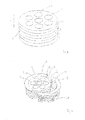
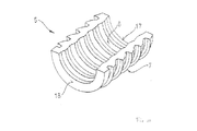
- Figure 1 shows a part of an assembly for providing in an opening a sealing through which at least one cable, pipe or duct extends.
- the part shown in Figure 1 concerns a transit-unit 1 of a relatively inflexible material, for instance, high molecular density polyethylene.
- the transit-unit 1 comprises one or, as shown in Figure 1 , a plurality of conduits 2, each extending in a longitudinal direction L of the transit-unit 1.
- each conduit 2 is suitable for receiving one cable 10, or even more cables 10.
- cables 10 as extending through the conduits 2 or as passed through the plurality of conduits 2.
- a pipe or duct could be passing through a number of the conduits.
- a combination of for instance one cable and one pipe could be passing through one or more conduits 2.
- the transit-unit 1 has an outer circumference 3 which is provided with a first profile 4.
- Figure 2 shows again transit-unit 1 as well as another part of the assembly, namely an outer plug 15 comprising, in this example, two segmental longitudinal parts 5.
- Each of these two segmental longitudinal parts 5 is made of an elastic material, compared with the inflexible material used for the transit-unit 1.
- the segmental longitudinal parts 5 are preferably made of a silicone rubber, preferably with a Shore A hardness of about 72°.
- the outer plug 15 has an inside 6 which is provided with a second profile 7.
- the transit-unit 1 is preferably made of an inert material, i.e. a non-metal and/or non-corrosive material.
- the material is preferably "dirt-repellent" and/or easily cleaned, so that just before use any sand can be wiped off, and such or similar potential sources for leakages can be removed.
- the material is preferably a high durability material.
- High molecular density polyethylene would be a good choice for the inflexible material of the transit-unit 1. This would also ensure that the material used for the transit-unit is relatively light, advantageous for the use on board of vessels.
- the second profile 7 comprises in this example a number of radially inwardly extending ribs 12, of which each extends in the circumferential direction.
- the outer plug 15 partly surrounds the transit-unit 1 at the outer circumference 3.
- One of the two segmental longitudinal parts 5 is positioned against the outer circumference 3 of the transit-unit 1.
- the other segmental longitudinal part 5 is still at some distance from the outer circumference 3 of transit-unit 1 but, as indicated by arrow A, can be moved more closely to the outer circumference 3 of transit-unit 1 so that at the outer circumference 3 the transit-unit is virtually fully surrounded by the outer plug 15.
- the outer plug 15 surrounds the transit-unit 1 at the outer circumference 3 to the extent that each of the segmental longitudinal parts is placed with its inside against the outer circumference and so that the first and second profiles 4, 7 match each other, the assembly is said to be in an assembled condition.
- the outer plug 15 can also be said to have a longitudinal direction which coincides with the longitudinal direction of the transit-unit 1 when the assembly is in the assembled condition.
- Figure 3 shows the outer circumference 3 of transit-unit 1 as well as its first profile 4.
- the first profile 4 comprises in this example a number of radially outwardly extending ribs 11 of which each extends in the circumferential direction.
- a part of the outer plug 15, namely the second profile 7 at the inside 6 of the outer plug 15, is also shown.
- a tiny gap is shown between the outer circumference 3 of transit-unit 1 and the inside 6 of segmental longitudinal part 5 of the outer plug 15. This gap more clearly enables the form of the first profile 4 and the form of the second profile 7 to be shown.
- first profile 4 and the second profile 7 match such that movement of transit-unit 1 relative to the outer plug 15 would be inhibited in the longitudinal direction L if the first profile 4 and the second profile 7 would truly have contact.
- this example would be contact over the entire circumference 3 with the inside 6 of segmental longitudinal part 5 of the outer plug 15.
- complete contact over the entire outer circumference 3 of transit-unit 1 is certainly advantageous, it is conceivable that in other embodiments there is not contact over the entire outer circumference, even though still the first profile 4 and the second profile 7 are also for other such embodiments considered to be matching such that movement of transit-unit 1 relative to the outer plug 15 is inhibited in the longitudinal direction L.
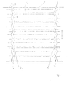
- Figures 4 , 5 and 6 of the present application correspond respectively to Figures 4 , 1 and 5A of WO 2007/028443 (incorporated herein by reference) .
- the reference signs shown in Figures 4 , 5 and 6 of the present application correspond to those used in the description of WO 2007/028443 A1 .
- FIG. 4 For a more detailed description of an example of profile 7 of an outer plug 15 as presented in Figure 4 of the present application, reference is made to WO 2007/028443 A1 as that outer profile is very suitable for an outer plug 15 in the presently described invention.
- the second profile 7 depicted in Figures 4 , 5 and 6 is according to the prior art used for providing annular contact surfaces against an outer cylindrical surface of a cable, pipe or duct, which is normally smooth.
- the second profile 7 as shown in Figures 4-6 is particularly suitable for sliding in a longitudinal direction over such an outer surface of a pipe, cable or duct as needed when the plug is inserted for sealing. Strikingly, the very same profile can, in combination with a matching counter profile, sufficiently inhibit sliding in a longitudinal direction.
- the outer plug 15 is provided with an outside having a number of outer ribs (in Figures 4 , 5 and 6 labelled 3,11). In the example shown, these ribs 3, 11 have the shape of a sawtooth.
- the tops (in Figures 4 , 5 and 6 labelled 8a) are spaced apart in the longitudinal direction for realizing, in use of the assembly, annular contact surfaces closed upon themselves in circumferential direction for sealing contact with an inner wall of the opening.
- the thickness of the segmental longitudinal parts 5 is in radial direction such that when the outer plug 15 is inserted into the opening and the outer ribs 3, 11 are pressed inwards, the resulting pressure is passed on to the inner profile 7, and if this is provided with inwardly extending ribs 12, also onto these ribs. As a consequence, the inner profile 7 of the outer plug 15 is pressed onto the outer profile 4 of the outer circumference 3 of the transit-unit 1. The grip of the outer plug 15 on the transit-unit 1 is therefore strong, holding the transit-unit in place.
- the radial thickness of the outer plug 15 is preferably between 10 and 22 mm, more preferably ranges from 12 to 20 mm. On the basis of routine experiments, a skilled person will be able to determine the optimal difference, in relation to the materials and mechanical properties thereof as selected for the transit-unit and the outer plug.
- the outer plug 15 is provided with a flange 13.
- segmental longitudinal parts 5 are ideally prepared by an injection moulding process or a compression moulding process, in which a vulcanizable material, possibly on the basis of silicone, is injected into a mould or compressed in a mould, and vulcanized.
- a vulcanizable material possibly on the basis of silicone
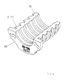
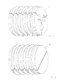
- Figure 7 shows the assembly in the assembled condition, i.e. the outer plug 15 as formed by the two segmental longitudinal parts 5 surrounds the transit-unit 1 at the outer circumference 3.
- the assembly, shown in Figure 7 is not in an installed condition. That is, the assembly as shown in Figure 7 has not been inserted into an opening for being subjected to a condition wherein the transit-unit is clamped in the opening by the outer plug 15. It follows that the assembly as shown in Figure 7 is free from radial compression.
- the two segmental longitudinal parts 5 do not abut each other in a circumferential direction. The at least two segmental longitudinal parts 5 do thus not form an outer plug 15 which is fully closed in itself in the circumferential direction.
- Another way of describing the relative dimensions of the transit-unit 1 and the outer plug 15 in a non-assembled condition of the assembly and in an assembled condition of the outer plug 15, is as follows. At each position along the longitudinal direction the diameter of the inside of the outer plug 15 is smaller than the diameter of the outer circumference 3 of the transit-unit 1 at the corresponding position along the longitudinal direction. As an example, for a transit-unit having a circular cross-section along the transverse direction, and a diameter of say 160 mm, the diameter of the outer plug 15 at corresponding positions along the longitudinal direction, is typically 159 mm (the outer plug 15 is in the assembled condition and the assembly is in the non-assembled condition). This difference in diameter of 1 mm may be slightly more or slightly less. On the basis of routine experiments, a skilled person will be able to determine the optimal difference.
- Figure 8 shows the assembly as put in the assembled position and as put in the installed condition.
- the assembled assembly has been inserted into the end of a pipe 8 so that the transit-unit 1 is held in a clamped position by the outer plug 15.
- the two segmental longitudinal parts 5 of the outer plug 15 now abut each other at both possible positions for such abutment so that in circumferential direction the outer plug 15 is closed in itself.
- the inner diameter of the outer plug 15 now corresponds to the outer diameter of the transit-unit 1, at the corresponding positions along the longitudinal direction L.
- a total length of the inside of the outer plug 15 measured in circumferential direction is now equal to the total length of the outer circumference of the transit-unit 1, at corresponding positions along the longitudinal direction.
- profile 4 of the outer circumference 3 of the transit-unit 1 has a smooth surface, allowing for optimal sliding of the outer plug 15 along the circumferential direction as might occur during insertion and the accompanying radial compression of the outer plug 15, as described above.
- the outer plug 15 is preferably made of silicon rubber having a Shore A hardness ranging from 65° up to 75°, preferably 68°-70°, and even more preferably about 72°.
- Figure 9 shows a cross-section of a transit-unit 1, taken along the longitudinal direction L thereof.
- Each conduit 2 is seen to have a restricted part 9.
- the example shown is seen to have two conduits 2. However, it is of course equally possible that the transit-unit has only one conduit 2, or a much larger number of conduits 2.
- the restricted part 9 is formed by a part of the conduit 2 that has a diameter which is smaller than the diameter of an unrestricted part of the conduit 2. This can also be seen in Figures 7 and 8 .
- An entrance of the unrestricted part of each conduit 2 has preferably a rim which is rounded-off, so as not to have a sharp edge which could damage the inner plug 16 on insertion into the conduit 2.
- the transit-unit 1 comprising one or a plurality of conduits 2 of which each has a restricted part 9
- the restricted part 9 is formed by a part which is mounted towards one end of an unrestricted part of conduit 2.
- the transit-unit 1 is a multiple-part device, having at least one part in which the conduits are unrestricted and another part which effectively lengthens the conduits and therewith adds on a restricted part of the conduits.
- Figures 10 , 11 and 12 correspond respectively to Figures 2 , 3 and 4 of WO 2008/023058 A1 (incorporated herein by reference).
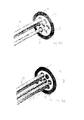
- Figure 10 shows one segment of a segmented inner plug 16.
- Figure 11 of the present application shows a view onto the inside of such an inner plug 16 and
- Figure 12 shows in more detail a cross-section taken along a longitudinal direction of such an inner plug 16.
- each of the inner plugs 16 is free from a flange.
- each of the inner plugs 16 has a length such that the entire inner plug 16 fits in the restricted part of the respective conduit 2. This means that a distribution of the conduits is determined by the dimension of the conduits 2 and the necessary thickness of the material between these conduits 2.
- the dimensions of the inner plugs 16 do not play a role in the distribution of the conduits 2 over the transit-unit 1. That is because each inner plug 16 fits in its entirety in a conduit, so that only the conduit itself has to be taken into account for designing the transit-unit in a way that the conduits are advantageously distributed over the transit-unit.
- the inner plugs 16 can be pressed in a longitudinal direction toward the unrestricted part 9 of the conduit 2. This allows for a form of "dynamic sealing", meaning that the sealing improves as the pressure difference over the length of the plug increases.
- dynamic sealing meaning that the sealing improves as the pressure difference over the length of the plug increases.
- the function of the inner plugs 16 is to clamp the pipe, cable 10 or duct effectively to the transit-unit 1, so that the transit-unit 1 is held in place by the clamping of the outer plug 15 and the clamping to each of the cables 10, pipes or ducts extending through the transit-unit. It follows that the overall clamping is better if the number of conduits is higher.
- Figure 13 shows an example in perspective view of an inner plug 13 which could seal space within a conduit 2 that remains when three cables extend through that conduit 2.
- Figure 14 shows an example of an inner plug 14 which can be used in a conduit 2 through which, for the time being, no cable, pipe or duct extends. This is often referred to as a blind plug. It is possible that the assembly as initially installed in an opening is only provided with blind plugs 14. It can even be installed in a factory where a pre-fabricated wall is prepared for transport to a construction site. This has the advantage that each conduit 2, or at least the unrestricted part thereof, remains free from dirt until the blind plug is removed for passing a cable through the conduit and inserting an inner plug 16.
- Figure 13 and Figure 14 correspond to respectively Figure 17 and Figure 18 of WO 2008/023058 A1 , to which the reader is referred for a further description of these type of plugs.
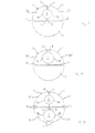
- Figures 15, 16 and 17 show schematically cross-sections taken along a transverse direction of alternative inner plugs 16 which could equally be part of an assembly according to the invention for insertion into one of the conduits 2 of transit-unit 1.
- Figures 15, 16 and 17 correspond respectively to Figures 1A, 1B and 1C respectively of international patent application PCT/EP2010/050986 (incorporated herein by reference), to which the reader is referred for more details about these examples of inner plugs 16.
- Other examples are also described in GB 2171139A (incorporated herein by reference). Particularly those shown in Figures 5-8 thereof can suitably be employed in an assembly according to the invention.
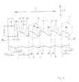
- Figure 18 shows various intermediate stages reached by carrying out steps of a method for providing in an opening a sealing system through which at least one cable, pipe or duct extends.
- the method entails providing an assembly as described above.
- the method comprises providing a transit-unit, for instance a transit-unit 1 as described above, of a relatively inflexible material, which could be a high-density polyethylene.
- the transit-unit 1 comprises in this example a number of conduits 2 extending in a longitudinal direction of the transit-unit 1. Each conduit 2 is suitable for receiving one cable, pipe or duct.
- the transit-unit has an outer circumference which is provided with a first profile (not shown in Figure 18 ).
- the method further comprises providing an outer plug 15 comprising at least two segmental longitudinal parts 5 which are of an elastic material relative to the inflexible material of transit-unit 1.
- the outer plug 15 has an inside (not shown in Figure 18 ) which is provided with a second profile (not shown in Figure 18 ).
- Figure 18(a) shows the transit-unit 1 and the outer plug 15 in an assembled condition as a result of putting the outer plug 15 and the transit-unit 1 such that the outer plug 15 is positioned so as to surround the transit-unit 1 at the outer circumference.
- the arrows shown in Figure 18(a) indicate a movement of the assembled assembly into the opening.
- Figure 18(b) also shows the result of another method step, namely passing a cable 10 through one of the conduits 2. In case there is a plurality of cables 10, pipes or ducts, these will then be passed through the plurality of conduits 2.
- the method also comprises providing for each of the conduits 2 a segmented inner plug 16 of an elastic material, compared with the inflexible material of the transit-unit 1.
- a segmented inner plug 16 of an elastic material compared with the inflexible material of the transit-unit 1.
- An example of such a plug, and more details thereof, are shown in Figures 10-17 and described in the accompanying description thereof, and even in more detail described in documents referred to herein above.
- Figure 18(d) shows a step of inserting in a conduit 2 one of the segmented inner plugs 16 for sealingly filling a space in the respective conduit 2 between an inner circumferential wall of the conduit 2 and the cable 10.
- Figure 18(e) shows the end result of that step.
- Figure 18 (f) shows the result after repeating the steps of passing a cable through a conduit and inserting in that conduit one of the segmented inner plugs 16 for sealingly filling a space in that conduit 2 between an inner circumferential wall of the conduit 2 and the cable 10 passed through that conduit 2.
- Figure 18 (g) shows an end result of an embodiment of such a method according to the invention. It is to be noted that one of the conduits 2a is in this example only provided with a blind segmented inner plug 14, leaving that conduit 2 available for use in the future.
- Figure 19 shows in a perspective and semi-exploded view an opening into which at each end of the opening an assembly according to the invention is provided, using a method as described above.
- the assembly can be provided such that a variety of cables, pipes or ducts can be passed through the opening in a way that the opening is neatly sealed off.
- an assembly according to the invention could easily be scaled up and another embodiment of an assembly according to the invention can easily be scaled down.
- the down-scaled embodiment could be put in a conduit of the up-skilled embodiment.
- the sealing can exhibit some flexibility in the longitudinal direction.
- the plug can be compressed in the longitudinal direction, particularly when the conduit comprises the above-described restricted part.
- the transit-unit is somewhat flexibly suspended in the opening by the clamping function of the outer plug 15. This equally applies to the transverse direction. A slight movement of the cable in the transverse direction can initially be absorbed by the elastic inner plug 16, particularly if that is one as described above. However, also the entire transit-unit 1 is suspended flexibly with respect to the transverse direction.
- the transit-unit is shown as cylindrical. Also elliptical and/or slightly conical transit-units can be used.
- the outer plug 15 can have a corresponding inside. Also the shape of the opening can differ from a cylindrical configuration. Rectangular openings, possibly with rounded corners may also be provided with an assembly according to the invention.
- the outer plug and the transit-unit will then have dimensions which accommodate for instalment in such an opening.
- the conduits may for such an embodiment still be cylindrical.
- the first and second profile can be such that their mechanical interplay, i.e. the keying function, is more pronounced.
- the outer plug 15, particularly the inside thereof, might need to be designed exclusively for use in an assembly according to the invention.
- the transit-unit may be provided with a locker plate, which could be screwed against the transit-unit so as to lock the inner plugs 16 in their respective conduits.
- a locker plate can form the restrictive parts but also be in addition to the restrictive parts of the conduit and at a side of the conduit opposite the side having the restricted part.
- the sealing as provided with a method according to the invention and/or with use of an assembly according to the invention will be watertight, can sustain a pressure difference between one side of the opening and the other side, and can be fire-resistant, particularly if the materials for both the transit-unit 1 and the outer and inner plugs are selected for that purpose.
- the transit-unit 1 can be made of a fire-resistant rubber, just as the outer plug and the inner plugs. However, the transit-unit 1 would then preferably have a Shore A hardness of about 90°.
Landscapes
- Engineering & Computer Science (AREA)
- General Engineering & Computer Science (AREA)
- Mechanical Engineering (AREA)
- Architecture (AREA)
- Civil Engineering (AREA)
- Structural Engineering (AREA)
- Installation Of Indoor Wiring (AREA)
- Connector Housings Or Holding Contact Members (AREA)
- Laying Of Electric Cables Or Lines Outside (AREA)
- Gasket Seals (AREA)
- Quick-Acting Or Multi-Walled Pipe Joints (AREA)
Abstract
Description
- The invention is related to a sealing assembly for providing in an opening a sealing system through which at least one cable, pipe or duct extends.
- Such an opening may comprise a tubular passage in a floor, deck or a partition. Another possibility is that the opening comprises a pipe in which another pipe is at least partly received.
- Such a system can thus be used for, for instance, two connected pipes having mutually different diameters. One of the pipes may, for instance, form a house service connection and have a smaller diameter than a pipe which forms the main line or is a branch thereof. A system to which the invention relates is suitable for sealing the space located between the pipes.
- It is also possible that cables for, for instance telephone, electricity, and television are fed through such pipes connected with one another. Another possibility is using the system as a seal between glass fibre cables and protective tubes.
- Such a system may also be used for walls of buildings, particularly foundation walls and floors but also ceilings or roofs where, by means of "lost plastic tube parts" passages are left open in the poured concrete for feeding through tubes for water or gas, or cables. Of course, the passage may also be provided in a concrete base with the aid of a drilling method.
- Further, a system to which the invention relates can be used in the construction and/or maintenance of new buildings, ships and offshore installations. Sections in such constructions are usually formed by placing prefabricated partitions according to a predetermined plan, for instance in a dock of the shipyard where a vessel is being built. Even before the partitions are placed, feed-through sleeves can be provided in the partitions, for instance with the aid of a welding method.
- The space between the feed-through sleeve and at least one tube, duct or cable is herein below often simply referred to as "the space".
-
GB 2186442 - The forces needed for compression are very high and partly passed on to the ducted pipe or cable, often non-hydrostatically.
- This system cannot distribute the load evenly throughout the stacking of blocks. In fact, the ducted pipe or cable will carry a part of the load and prevent an even distribution. The blocks which are much less subjected to compression "in the shade" of the ducted pipe or duct can easily be forced out as the pressure is not passed on to these blocks.
- This system is not suitable for so-called coax cables as the pressure applied, particularly when this is non-hydrostatic, will undesirably affect the impedance. This system is also not suitable for glass fibers (often used for transmission of signals formed by light-waves) as any pressure, particularly when this is non-hydrostatic, would unpredictably affect the performance in transmission.
- Another problem is the uneven deformation of the rubber, which reduces the flexibility of the transit system. This can be detrimental when a part of the system is suddenly exposed to a much higher pressure, and such flexibility would be advantageous.
- Not only is the system difficult to install, time-consuming, costly, requires a large inventory control, and leads to an unbalanced distribution of pressure, the system further works unsatisfactorily in the long-run. Rubber, even well vulcanised rubber, has a natural relaxation occurring over time. When the rubber has not been properly saturated or vulcanized, also chemical relaxation can occur. This enhances the overall relaxation of the rubber. As a consequence of this, compression bolts or nuts of the compression and packer system of the system described in
GB 2186442 - A further problem is that a change in temperature will, due to thermal expansion or shrinkage, result in loosening or over-tightening of the compression bolts, resulting in respectively weakening the sealing and irreversible (permanent) deformation of the rubber.
- In particular when plastic pipes or cables with plastic braidings extend through the feed-through sleeve, the outer surface of these pipes or cables is subjected to radial inward pressure and the outer diameter of these plastic pipes or cables may decrease due to a phenomenon known as "creep". If this occurs, compression bolts and nuts of the compression and packer system should be retightened even more frequently as the integrity of the sealing provided by the compressed rubber blocks and the compressed plastic pipes or cables diminishes by both physical phenomena, creep and relaxation. However, no matter how frequently the compression bolts and/or nuts are retightened, immediately after retightening, the phenomena of relaxation of the rubber and creep of a plastic pipe will continue to occur so that the integrity of the sealing immediately deteriorates.
- The system does not allow for partly or completely replacing the rubber blocks, as new rubber blocks would not fit tightly anymore to the outer walls of the plastic pipes or the plastic braidings, particularly when these were unpredictably and unequally deformed due to the creep phenomenon described above.
- Known are systems where a rubber ring is coaxially placed in a feed-through sleeve around a pipe ducted through the conduit. The rubber ring is then compressed between steel ring shaped plates. Although this leads to the building up of radial forces of equal strength, the problems of relaxation of the rubber and, in case of plastic pipes, the problems of creep necessitate also for these systems frequent retightening of the compressing steel plates.
-
WO 2004/111513 describes a system, in more detail a plug, made of an elastically deformable material for insertion in a space between an inner wall of a feed-through sleeve, and a pipe, cable or duct extending through that sleeve. The plug usually comprises at least two segmental longitudinal parts for forming a sealing plug which can be received in the space. The longitudinal parts are each provided with an outside which comprises a number of outer ribs spaced apart in a longitudinal direction for realizing, in use, annular contact surfaces which are each closed in itself in a circumferential direction between the sealing plug and the inner wall of the opening. - Each of the longitudinal parts is further provided on the inside with a number of inner ribs for realizing, in use, annular contact surfaces of which each is closed in itself in a circumferential direction between the sealing plug and the pipe, cable or duct extending through the opening.
- Each of the longitudinal parts is further provided with an outer collar intended to be placed against an outer edge of the opening. When the plug is assembled these collars are part of a flange which is such that forces can be exerted onto the flange for inserting the longitudinal parts. The flange is designed such that it can be placed against the outer edge of the opening. The outer edge of the opening is thus covered by the flange. The flange further ensures equal insertion, so that the outer ribs of the longitudinal parts are lined up to form the annular contact surfaces and such that the inner ribs are lined up to form the annular contact surfaces.
- An advantage of this sealing system is that it is very easy to insert, and after applying grease to the longitudinal parts, manual insertion may even be possible. Due to the flange, it is highly unlikely that the plug will be further pushed into the feed-through sleeve or opening, not even when a very high pressure is applied to the flange. It has been shown that this sealing system retains its sealing integrity also when a very high pressure is applied to the side of the plug that is first inserted into the opening or conduit sleeve. Only after application of a very high pressure on that end of the plug, may the plug be forced out of the conduit sleeve or opening. Another advantage is that the ribs provide some flexibility in the sealing system, so that no retightening is needed. When the rubber relaxes, the ribs still provide annular contact surfaces and thus a sealing remains intact. This response also applies to the unlikely occurrence of creep which would result in a smaller diameter of a plastic pipe extending through the opening or conduit sleeve. As the actual radial load applied to a plastic pipe extending through the feed-through sleeve will, due to the relaxation of the rubber, decrease in time, the possible occurrence of creep will decrease rather than increase.
-
WO 2008/023058 describes a system for providing a sealing system for a situation wherein one or a plurality of cables, pipes or ducts extend through an opening. The system comprises a transit-unit which is sealingly fixed or fixable into or onto the opening. The transit-unit comprises one or a plurality of conduits which are each suitable for receiving at least one of the plurality of cables, pipes or ducts. Each of the conduits is further suitable for receiving an elastically deformable plug for sealingly filling space between an inner circumferential wall of the conduit and the one or more cables, pipes or ducts extending through that conduit. This system is very suitable where the opening is in a partition, such as a ceiling or floor made from steel or another metal alloy. -
WO 2008/023058 describes that the transit-unit itself can be of steel or aluminium. The transit-unit is normally provided with a flange for welding the transit-unit to a steel or aluminium construction element or for bolting the transit-unit to a partitioning construction element. Under these circumstances, such a system can sustain a high pressure, even a sudden increase in load. However, such a way of sealingly fixing the transit-unit into or onto a conduit sleeve or another form of an opening, requires careful planning a long time ahead of the actual construction, is time-consuming, requires input of skilled and thus costly workers and disallows for easy replacement of the transit-unit by, for instance, another transit-unit with differently sized conduits. - It is an object of the present invention to solve at least one of these problems associated with sealingly fixing the transit-unit into or onto an opening.
- The invention provides a sealing assembly for providing in an opening a sealing system through which at least one cable, pipe or duct extends. The system comprises a transit-unit of a relatively inflexible material. The transit-unit comprises one or a plurality of conduits extending in a longitudinal direction of the transit-unit. Each conduit is suitable for receiving at least one of the cables, pipes or ducts. The transit-unit has an outer circumference which is provided with a first profile. The assembly further comprises an
outer plug 15 comprising at least two segmental longitudinal parts which are of an elastic material, compared with the inflexible material of the transit-unit. Theouter plug 15 has an inside which is provided with a second profile. In the assembled condition, theouter plug 15 surrounds the transit-unit at the outer circumference. In an assembled condition, the first profile and the second profile match such that movement of the transit-unit relative to theouter plug 15 is inhibited in the longitudinal direction. - This assembly allows for putting the
outer plug 15 and the transit-unit in the assembled condition and inserting theouter plug 15 and the transit-unit in the assembled condition into the opening so that the transit-unit is clamped in the opening by theouter plug 15. This improves and simplifies the sealingly fixing of the transit-unit into the opening. - Furthermore, as will be explained later on in more detail, the system as installed will have additional resilience due to the
outer plug 15, in both the longitudinal direction and the transverse direction. - In an embodiment of an assembly according to the invention, it applies that in a non-assembled condition of the assembly and in an assembled condition of the
outer plug 15 in which theouter plug 15 is free from radial compression, a total length of the inside of theouter plug 15 measured in circumferential direction is, at each position along the longitudinal direction, smaller than the total length of the outer circumference of the transit-unit at the corresponding position along the longitudinal direction. This improves the capability of theouter plug 15 to clamp the transit-unit in the opening, which can be explained as follows. It follows from the relative length dimensions of the inside of theouter plug 15 and the outer circumference of the transit-unit that there will, somewhere along the circumferential direction, be a gap between the two segments which form theouter plug 15 when the assembly is put in the assembled condition. This gap (there could be two or more gaps, depending on the number of segments), allows for expansion of a segment in the circumferential direction once theouter plug 15 is subjected to a radial compression. A radial distance between the transit-unit and the inner wall of the opening will generally be relatively small. Theouter plug 15 can easily be compressed in radial direction due to the possibility to lengthen each of the at least two segments of theouter plug 15 in circumferential direction of the plug. This contributes to the ease of inserting the assembled assembly into the opening. Opposed requirements of conveniently installing the assembly and realizing a tight sealing are thus both met. Theouter plug 15 will seal off the annular space between the transit-unit and the inner wall of the opening as well as tightly hold the transit-unit in the opening. - Furthermore, as the
outer plug 15 can be relatively thin, the transit-unit can occupy a large cross-section of the opening, allowing for many cables and/or pipes and/or ducts to be extended through the transit-unit and the opening. Such a fixing of the transit-unit does not require workers with special skills. The insertion of the system into the opening is not time-consuming and can be carried out at any desired moment in time. It also allows for non-invasive removal of the transit-unit should this be needed at some stage. The opening will not be damaged by such removal. Re-filling the opening with a similar assembly is then no problem. - According to an embodiment of an assembly according to the invention, in a non-assembled condition of the assembly and in an assembled condition of the outer plug 15 (in which the
outer plug 15 is free from radial compression), at each position along the longitudinal direction the diameter of the inside of theouter plug 15 is smaller than the diameter of the outer circumference of the transit-unit at the corresponding position along the longitudinal direction. On putting the assembly in the assembled and installed condition, the diameter of the inside of theouter plug 15 increases to fit to the outer circumference of the transit-unit. This contributes to generating the forces for clamping of the transit-unit in the opening. Also in that process, the segments of theouter plug 15 might lengthen in circumferential dimension. - In an embodiment of an assembly according to the invention, each of the conduits comprises an unrestricted part and a restricted part which are in longitudinal direction next to each other. Such an embodiment allows for the insertion of segmented
inner plugs 16 for sealingly filling a space in the respective conduit between an inner circumferential wall of the unrestricted part of the conduit and the at least one cable, pipe or duct extending through that conduit. Advantageously, the restricted part hinders movement of the insertedinner plug 16 along the restricted part, providing the possibility for dynamic sealing (as will further be elaborated on below), although this is not essential within the present invention. Furthermore, such a restricted part ensures that theinner plug 16 cannot be inserted too far i.e. not to the extent that it would be pushed out at the other end of the conduit. This advantageously has consequences for densely distributing the conduits over the transit-unit (as will also further be elaborated on below). - In an embodiment of an assembly according to the invention, the assembly ideally further comprises for each of the conduits a segmented
inner plug 16 of an elastic material, compared with the inflexible material of the transit-unit, for sealingly filling a space in the unrestricted part of the conduit between an inner circumferential wall of the conduit and the at least one cable, pipe or duct extending through that conduit. Such segmentedinner plugs 16 usefully contribute to the further sealing in a simplified way. Use can be made of existing plugs, making the sealing assembly of the present invention economically attractive. Although the outer diameter of the segmented inner plug is clearly predetermined on the basis of the inner diameter of the conduit of concern, the sealing system is flexible with regard to the outer diameters of the cable, pipe or duct. The segmentedinner plug 16 can be provided with an inner diameter suitable for use with the outer diameter of that cable, pipe or duct. - In an embodiment of an assembly according to the invention, each of the
inner plugs 16 has a length such that the entireinner plug 16 fits in the unrestricted part of the respective conduit. This has the advantage that a distribution of the conduits does not have to take into account dimensions of theinner plugs 16 which prevent the plug from fitting in the unrestricted part of the conduit. That in turn means that the distribution can be determined exclusively by the material strength of the transit-unit, which determines the minimum thickness of parts of the transit-unit that will be exposed to high pressures. The distribution of conduits can thus be denser if a stronger material is used for the transit-unit. - In an embodiment of an assembly according to the invention, each of the
inner plugs 16 is free from a flange. This provides a very practical embodiment ofinner plugs 16, and allows for the dense distribution of the conduits over the transit-unit. The density is only determined by the thickness of the wall between the conduits, not by the need to avoid overlaps of flanges of inner plugs 16. - In an embodiment of an assembly according to the invention, the
outer plug 15 is provided with a flange. Such a flange prevents inserting the assembly too far into the opening and offers a surface against which force can be applied for inserting the assembled assembly into the opening. Furthermore, also suchouter plugs 15 exist and are commercially available, making the sealing assembly according to the invention in many aspects economically attractive. - In an embodiment of an assembly according to the invention, the first profile comprises a number of radially outwardly extending ribs which each extends in the circumferential direction. Advantageously, this allows for a uniform resistance along the circumference of the transit-unit against a movement in the longitudinal direction of the transit-unit relative to the
outer plug 15. - In an embodiment of an assembly according to the invention, the second profile comprises a number of radially inwardly extending ribs of which each extends in the circumferential direction. Advantageously,
outer plugs 15 having such a second profile are known and are commercially available. Such ribs are for realizing annular contact surfaces with, for instance, an outer surface of a pipe which it holds in an opening in a clamped and sealed fashion. It follows that the assembly can be produced in a relatively cost-effective way, and no new moulds need to be produced for the manufacture of such outer plugs 15. - In an assembly according to the invention, in the assembled condition the positions of the inwardly extending ribs and the outwardly extending ribs alternate each other in the longitudinal direction. This provides for an optimum way of hindering movement in the longitudinal direction of the transit-unit relative to the
outer plug 15. - The invention is further related to a method for providing in an opening a sealing through which at least one cable, pipe or duct extends. Such a method comprises providing a transit-unit of relatively inflexible material. The transit-unit comprises one or a plurality of conduits extending in a longitudinal direction of the transit-unit. Each conduit is suitable for receiving one of the at least one cable, pipe or duct. The transit-unit has an outer circumference which is provided with a first profile.
- The method further comprises, providing an
outer plug 15 comprising at least two segmental longitudinal parts which are of an elastic material, compared with the inflexible material of the transit-unit. Theouter plug 15 has an inside which is provided with a second profile. - The method further comprises providing for each of the conduits a segmented
inner plug 16 of an elastic material, compared with the inflexible material of the transit-unit, for sealingly filling a space in the conduit between an inner circumferential wall of the conduit and the at least one cable, pipe or duct. - In an assembled condition the
outer plug 15 surrounds the outer circumference of the transit-unit. In that condition, the first profile and the second profile match each other such that movement of the transit-unit relative to theouter plug 15 is inhibited in the longitudinal direction. - The method further comprises:
- ● putting the
outer plug 15 and the transit-unit in the assembled condition by positioning theouter plug 15 such that it surrounds the transit-unit at the outer circumference; - ● inserting the
outer plug 15 and the transit-unit in the assembled condition into the opening so that the transit-unit is clamped in the opening by theouter plug 15; - ● passing at least one cable, pipe or duct through the plurality of conduits; and
- ● inserting in each conduit one of the segmented
inner plugs 16 for sealingly filling a space in the respective conduit between an inner circumferential wall of the respective conduit and the at least one cable, pipe or duct extending therethrough. - This provides for a simple and straightforward way of providing in an opening a sealing system through which at least one cable, pipe or duct extends. The method is simple and likely to be foolproof, can be carried out in a relatively short space of time, and does not require the presence of extra equipment. Above all, it leads to a sealing system that is low-maintenance and that can serve a very long time.
- In an embodiment of a method according to the invention, the opening itself is a conduit in a transit-unit as referred to above. In such a method, the sealing is provided such that there is more than one possibility for responding dynamically to a sudden increase in pressure applied in the longitudinal direction. Also in transverse direction, there is more than one possibility for offering flexibility in case the cable, pipe or duct extending through the opening moves relative to the opening in transverse direction. This will later on be explained in more detail.
- The invention is further explained and illustrated in the accompanying drawing, in which:
-
Figure 1 shows a transit-unit of an embodiment of an assembly in accordance with the invention; -
Figure 2 shows a transit-unit and anouter plug 15 of an embodiment according to the invention; -
Figure 3 , a close-up view of a transit-unit and of a part of anouter plug 15 of an embodiment according to the invention; -
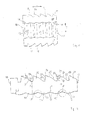
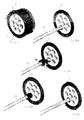
Figure 4 , a perspective view of one segmental longitudinal part of anouter plug 15 of an embodiment according to the invention; -
Figure 5 , a view onto an inside of a segmental longitudinal part of anouter plug 15 of an embodiment according to the invention; -
Figure 6 , in more detail, a cross-section along a longitudinal direction of a segmental longitudinal part of anouter plug 15 of an embodiment according to the invention; -
Figure 7 , a perspective view of a transit-unit and anouter plug 15 of an embodiment according to the invention in an assembled condition; -
Figure 8 , a perspective view of a transit-unit and anouter plug 15 of an embodiment according to the invention in the assembled and installed condition; -
Figure 9 , a cross-sectional view along a longitudinal direction of a transit-unit of an embodiment according to the invention; -
Figure 10 , a perspective view of one segment of aninner plug 16 of an embodiment according to the invention; -
Figure 11 , a view onto an inside of a segment as shown inFigure 10 ; -
Figure 12 , a more detailed cross-section along a longitudinal direction of a segment as shown inFigure 10 ; -
Figure 13 , in perspective aninner plug 16 of an embodiment according to the invention; -
Figure 14 , a perspective view of aninner plug 16 of an embodiment according to the invention; -
Figure 15 , schematically a view onto a cross-section along a transverse direction of aninner plug 16 of an embodiment according to the invention; -
Figure 16 , schematically a view onto a cross-section along a transverse direction of aninner plug 16 of an embodiment according to the invention; -
Figure 17 , schematically a view onto a cross-section along a transverse direction of aninner plug 16 of an embodiment according to the invention; -
Figure 18 (a)-(g) , perspective views of various stages reached during carrying out an embodiment of a method according to the invention; -
Figure 19 , a perspective and partly exploded view of the use of an embodiment according to the invention. -
Figure 1 shows a part of an assembly for providing in an opening a sealing through which at least one cable, pipe or duct extends. The part shown inFigure 1 concerns a transit-unit 1 of a relatively inflexible material, for instance, high molecular density polyethylene. The transit-unit 1 comprises one or, as shown inFigure 1 , a plurality ofconduits 2, each extending in a longitudinal direction L of the transit-unit 1. As more easily shown inFigures 18(b)-(g) , eachconduit 2 is suitable for receiving onecable 10, or evenmore cables 10. - In the following, reference is each time made to
cables 10 as extending through theconduits 2 or as passed through the plurality ofconduits 2. However, it is to be understood that instead of a cable, also a pipe or duct could be passing through a number of the conduits. Also a combination of for instance one cable and one pipe could be passing through one ormore conduits 2. Later on in this description, further reference is made to these possibilities. - The transit-
unit 1 has anouter circumference 3 which is provided with a first profile 4. -
Figure 2 shows again transit-unit 1 as well as another part of the assembly, namely anouter plug 15 comprising, in this example, two segmentallongitudinal parts 5. Each of these two segmentallongitudinal parts 5 is made of an elastic material, compared with the inflexible material used for the transit-unit 1. The segmentallongitudinal parts 5 are preferably made of a silicone rubber, preferably with a Shore A hardness of about 72°. Theouter plug 15 has an inside 6 which is provided with asecond profile 7. - To reduce the possibility of galvanic corrosion, the transit-
unit 1 is preferably made of an inert material, i.e. a non-metal and/or non-corrosive material. The material is preferably "dirt-repellent" and/or easily cleaned, so that just before use any sand can be wiped off, and such or similar potential sources for leakages can be removed. For a long life time, the material is preferably a high durability material. - High molecular density polyethylene would be a good choice for the inflexible material of the transit-
unit 1. This would also ensure that the material used for the transit-unit is relatively light, advantageous for the use on board of vessels. - As shown, the
second profile 7 comprises in this example a number of radially inwardly extendingribs 12, of which each extends in the circumferential direction. - In
Figure 2 , theouter plug 15 partly surrounds the transit-unit 1 at theouter circumference 3. One of the two segmentallongitudinal parts 5 is positioned against theouter circumference 3 of the transit-unit 1. The other segmentallongitudinal part 5 is still at some distance from theouter circumference 3 of transit-unit 1 but, as indicated by arrow A, can be moved more closely to theouter circumference 3 of transit-unit 1 so that at theouter circumference 3 the transit-unit is virtually fully surrounded by theouter plug 15. Once theouter plug 15 surrounds the transit-unit 1 at theouter circumference 3 to the extent that each of the segmental longitudinal parts is placed with its inside against the outer circumference and so that the first andsecond profiles 4, 7 match each other, the assembly is said to be in an assembled condition. Theouter plug 15 can also be said to have a longitudinal direction which coincides with the longitudinal direction of the transit-unit 1 when the assembly is in the assembled condition. -
Figure 3 shows theouter circumference 3 of transit-unit 1 as well as its first profile 4. The first profile 4 comprises in this example a number of radially outwardly extendingribs 11 of which each extends in the circumferential direction. A part of theouter plug 15, namely thesecond profile 7 at theinside 6 of theouter plug 15, is also shown. Purely for the sake of clarity, a tiny gap is shown between theouter circumference 3 of transit-unit 1 and theinside 6 of segmentallongitudinal part 5 of theouter plug 15. This gap more clearly enables the form of the first profile 4 and the form of thesecond profile 7 to be shown. It is clear that the first profile 4 and thesecond profile 7 match such that movement of transit-unit 1 relative to theouter plug 15 would be inhibited in the longitudinal direction L if the first profile 4 and thesecond profile 7 would truly have contact. As clearly shown, in this example that would be contact over theentire circumference 3 with theinside 6 of segmentallongitudinal part 5 of theouter plug 15. However, although such complete contact over the entireouter circumference 3 of transit-unit 1 is certainly advantageous, it is conceivable that in other embodiments there is not contact over the entire outer circumference, even though still the first profile 4 and thesecond profile 7 are also for other such embodiments considered to be matching such that movement of transit-unit 1 relative to theouter plug 15 is inhibited in the longitudinal direction L. - As shown in the example of
Fig. 3 , in the assembled condition the positions of the inwardly extendingribs 12 and the outwardly extendingribs 11 alternate each other in the longitudinal direction. Below, examples of each of the first and second profiles will be dealt with in more detail, particularly with reference to earlier published descriptions of such profiles. WhereasFigure 3 only shows parts of theinside 6 of segmentallongitudinal part 5, a perspective view of an example of such a segmentallongitudinal part 5 is presented inFigure 4 . - It is pointed out that
Figures 4 ,5 and6 of the present application correspond respectively toFigures 4 ,1 and5A ofWO 2007/028443 (incorporated herein by reference) . The reference signs shown inFigures 4 ,5 and6 of the present application correspond to those used in the description ofWO 2007/028443 A1 . - Consequently, for a more detailed description of an example of
profile 7 of anouter plug 15 as presented inFigure 4 of the present application, reference is made toWO 2007/028443 A1 as that outer profile is very suitable for anouter plug 15 in the presently described invention. Thesecond profile 7 depicted inFigures 4 ,5 and6 is according to the prior art used for providing annular contact surfaces against an outer cylindrical surface of a cable, pipe or duct, which is normally smooth. Thesecond profile 7 as shown inFigures 4-6 , is particularly suitable for sliding in a longitudinal direction over such an outer surface of a pipe, cable or duct as needed when the plug is inserted for sealing. Strikingly, the very same profile can, in combination with a matching counter profile, sufficiently inhibit sliding in a longitudinal direction. Instead of sliding, it provides a firm grip on a matching counter profile. Making use of the very same profile for anouter plug 15 in an assembly according to the present invention has the advantage that for developing the assembly no newouter plugs 15 will have to be designed. It is believed that such aprofile 7 works well as it provides a relatively large surface area that can be in contact with profile 4 of theouter circumference 3 of thetransit unit 1. - The
outer plug 15 is provided with an outside having a number of outer ribs (inFigures 4 ,5 and6 labelled 3,11). In the example shown, theseribs Figures 4 ,5 and6 labelled 8a) are spaced apart in the longitudinal direction for realizing, in use of the assembly, annular contact surfaces closed upon themselves in circumferential direction for sealing contact with an inner wall of the opening. - The thickness of the segmental
longitudinal parts 5 is in radial direction such that when theouter plug 15 is inserted into the opening and theouter ribs inner profile 7, and if this is provided with inwardly extendingribs 12, also onto these ribs. As a consequence, theinner profile 7 of theouter plug 15 is pressed onto the outer profile 4 of theouter circumference 3 of the transit-unit 1. The grip of theouter plug 15 on the transit-unit 1 is therefore strong, holding the transit-unit in place. In a practical embodiment, the radial thickness of theouter plug 15 is preferably between 10 and 22 mm, more preferably ranges from 12 to 20 mm. On the basis of routine experiments, a skilled person will be able to determine the optimal difference, in relation to the materials and mechanical properties thereof as selected for the transit-unit and the outer plug. - The
outer plug 15 is provided with aflange 13. It should be understood that the segmentallongitudinal parts 5 are ideally prepared by an injection moulding process or a compression moulding process, in which a vulcanizable material, possibly on the basis of silicone, is injected into a mould or compressed in a mould, and vulcanized. The use of a known profile for the inside 6 and a known profile for the outside ofouter plug 15 in the present invention significantly reduces the need for a new mould, and keeps the costs for the presently described system indeed at a very low level. -
Figure 7 shows the assembly in the assembled condition, i.e. theouter plug 15 as formed by the two segmentallongitudinal parts 5 surrounds the transit-unit 1 at theouter circumference 3. Although the segmentallongitudinal parts 5 are positioned relative to the transit-unit 1 so that the first profile 4 and thesecond profile 7 match such that movement of transit-unit 1 relative to theouter plug 15 is inhibited in the longitudinal direction, the assembly, shown inFigure 7 , is not in an installed condition. That is, the assembly as shown inFigure 7 has not been inserted into an opening for being subjected to a condition wherein the transit-unit is clamped in the opening by theouter plug 15. It follows that the assembly as shown inFigure 7 is free from radial compression. As can be seen inFigure 7 , the two segmentallongitudinal parts 5 do not abut each other in a circumferential direction. The at least two segmentallongitudinal parts 5 do thus not form anouter plug 15 which is fully closed in itself in the circumferential direction. - Should the transit-
unit 1 not have been positioned between the two segmentallongitudinal parts 5, it would then be possible to assemble theouter plug 15 such that the at least two segmentallongitudinal parts 5 form anouter plug 15 which is closed in itself in the circumferential direction. Another way of describing the above is to say that in the non-assembled condition of the assembly and an assembled condition of theouter plug 15 in which theouter plug 15 is free from radial compression, a total length of theinside 6 of theouter plug 15 measured in circumferential direction is at each position along the longitudinal direction smaller than the total length of theouter circumference 3 of the transit-unit 1 at the corresponding position along the longitudinal direction. From the embodiment shown inFig. 7 , it is clear that if the two segmentallongitudinal parts 5 were to be put in the assembled condition such that theouter plug 15 is closed in itself in the circumferential direction, then transit-unit 1 would not fit in thatouter plug 15. - Another way of describing the relative dimensions of the transit-
unit 1 and theouter plug 15 in a non-assembled condition of the assembly and in an assembled condition of theouter plug 15, is as follows. At each position along the longitudinal direction the diameter of the inside of theouter plug 15 is smaller than the diameter of theouter circumference 3 of the transit-unit 1 at the corresponding position along the longitudinal direction. As an example, for a transit-unit having a circular cross-section along the transverse direction, and a diameter of say 160 mm, the diameter of theouter plug 15 at corresponding positions along the longitudinal direction, is typically 159 mm (theouter plug 15 is in the assembled condition and the assembly is in the non-assembled condition). This difference in diameter of 1 mm may be slightly more or slightly less. On the basis of routine experiments, a skilled person will be able to determine the optimal difference. - Looking again at
Figure 3 , it is clear that as a result of the first profile 4 and thesecond profile 7 comparisons as described above only make sense if these apply to corresponding positions along the longitudinal direction L at thecircumference 3 of the transit-unit 1 and along theinside 6 of theouter plug 15. Corresponding positions are to be seen as positions which would have contact when the assembly is in the assembled condition, and the first and second profiles match each other such that movement of the transit-unit relative to theouter plug 15 is inhibited in the longitudinal direction. -
Figure 8 shows the assembly as put in the assembled position and as put in the installed condition. The assembled assembly has been inserted into the end of a pipe 8 so that the transit-unit 1 is held in a clamped position by theouter plug 15. The two segmentallongitudinal parts 5 of theouter plug 15 now abut each other at both possible positions for such abutment so that in circumferential direction theouter plug 15 is closed in itself. Clearly, the inner diameter of theouter plug 15 now corresponds to the outer diameter of the transit-unit 1, at the corresponding positions along the longitudinal direction L. Likewise, a total length of the inside of theouter plug 15 measured in circumferential direction is now equal to the total length of the outer circumference of the transit-unit 1, at corresponding positions along the longitudinal direction. Preferably, profile 4 of theouter circumference 3 of the transit-unit 1 has a smooth surface, allowing for optimal sliding of theouter plug 15 along the circumferential direction as might occur during insertion and the accompanying radial compression of theouter plug 15, as described above. Theouter plug 15 is preferably made of silicon rubber having a Shore A hardness ranging from 65° up to 75°, preferably 68°-70°, and even more preferably about 72°. -
Figure 9 shows a cross-section of a transit-unit 1, taken along the longitudinal direction L thereof. Eachconduit 2 is seen to have a restrictedpart 9. The example shown is seen to have twoconduits 2. However, it is of course equally possible that the transit-unit has only oneconduit 2, or a much larger number ofconduits 2. In the examples shown, therestricted part 9 is formed by a part of theconduit 2 that has a diameter which is smaller than the diameter of an unrestricted part of theconduit 2. This can also be seen inFigures 7 and8 . An entrance of the unrestricted part of eachconduit 2 has preferably a rim which is rounded-off, so as not to have a sharp edge which could damage theinner plug 16 on insertion into theconduit 2. - Although it is shown that the transit-
unit 1, comprising one or a plurality ofconduits 2 of which each has a restrictedpart 9, can be a one piece object, it is equally possible that therestricted part 9 is formed by a part which is mounted towards one end of an unrestricted part ofconduit 2. It is for instance possible that the transit-unit 1 is a multiple-part device, having at least one part in which the conduits are unrestricted and another part which effectively lengthens the conduits and therewith adds on a restricted part of the conduits. Once this insight is put to a person skilled in the art, a large number of possibilities for realising such embodiments will spring to mind of that person. -
Figures 10 ,11 and 12 correspond respectively toFigures 2 ,3 and4 ofWO 2008/023058 A1 (incorporated herein by reference).Figure 10 shows one segment of a segmentedinner plug 16.Figure 11 of the present application shows a view onto the inside of such aninner plug 16 andFigure 12 shows in more detail a cross-section taken along a longitudinal direction of such aninner plug 16. - The reference signs used in
Figures 10 ,11 and 12 of the present application correspond to those used in the description ofWO 2008/023058 A1 . For a detailed description of this example of aninner plug 16, reference is therefore made to that prior art document. Here, we merely point out that preferably, as shown, each of theinner plugs 16 is free from a flange. In an advantageous embodiment, each of theinner plugs 16 has a length such that the entireinner plug 16 fits in the restricted part of therespective conduit 2. This means that a distribution of the conduits is determined by the dimension of theconduits 2 and the necessary thickness of the material between theseconduits 2. The dimensions of theinner plugs 16 do not play a role in the distribution of theconduits 2 over the transit-unit 1. That is because eachinner plug 16 fits in its entirety in a conduit, so that only the conduit itself has to be taken into account for designing the transit-unit in a way that the conduits are advantageously distributed over the transit-unit. - Furthermore, it is possible for the
inner plugs 16 to be pressed in a longitudinal direction toward theunrestricted part 9 of theconduit 2. This allows for a form of "dynamic sealing", meaning that the sealing improves as the pressure difference over the length of the plug increases. For a more detailed description of this mechanism, reference is made toWO 2008/023058 . It is stressed here that the present invention is not specifically directed to such dynamic sealing. - The function of the
inner plugs 16 is to clamp the pipe,cable 10 or duct effectively to the transit-unit 1, so that the transit-unit 1 is held in place by the clamping of theouter plug 15 and the clamping to each of thecables 10, pipes or ducts extending through the transit-unit. It follows that the overall clamping is better if the number of conduits is higher. -
Figure 13 shows an example in perspective view of aninner plug 13 which could seal space within aconduit 2 that remains when three cables extend through thatconduit 2. -
Figure 14 shows an example of aninner plug 14 which can be used in aconduit 2 through which, for the time being, no cable, pipe or duct extends. This is often referred to as a blind plug. It is possible that the assembly as initially installed in an opening is only provided with blind plugs 14. It can even be installed in a factory where a pre-fabricated wall is prepared for transport to a construction site. This has the advantage that eachconduit 2, or at least the unrestricted part thereof, remains free from dirt until the blind plug is removed for passing a cable through the conduit and inserting aninner plug 16.Figure 13 and Figure 14 correspond to respectivelyFigure 17 andFigure 18 ofWO 2008/023058 A1 , to which the reader is referred for a further description of these type of plugs. -
Figures 15, 16 and 17 show schematically cross-sections taken along a transverse direction of alternativeinner plugs 16 which could equally be part of an assembly according to the invention for insertion into one of theconduits 2 of transit-unit 1. Advantageously, of such plugs, only one segment needs to be replaced should a pipe, cable or duct with another diameter than for which the presentinner plug 16 is suitable, be passed through theconduit 2.Figures 15, 16 and 17 correspond respectively toFigures 1A, 1B and 1C respectively of international patent applicationPCT/EP2010/050986 GB 2171139A Figures 5-8 thereof can suitably be employed in an assembly according to the invention. -
Figure 18 shows various intermediate stages reached by carrying out steps of a method for providing in an opening a sealing system through which at least one cable, pipe or duct extends. The method entails providing an assembly as described above. In detail, the method comprises providing a transit-unit, for instance a transit-unit 1 as described above, of a relatively inflexible material, which could be a high-density polyethylene. The transit-unit 1 comprises in this example a number ofconduits 2 extending in a longitudinal direction of the transit-unit 1. Eachconduit 2 is suitable for receiving one cable, pipe or duct. The transit-unit has an outer circumference which is provided with a first profile (not shown inFigure 18 ). The method further comprises providing anouter plug 15 comprising at least two segmentallongitudinal parts 5 which are of an elastic material relative to the inflexible material of transit-unit 1. Theouter plug 15 has an inside (not shown inFigure 18 ) which is provided with a second profile (not shown inFigure 18 ). -
Figure 18(a) shows the transit-unit 1 and theouter plug 15 in an assembled condition as a result of putting theouter plug 15 and the transit-unit 1 such that theouter plug 15 is positioned so as to surround the transit-unit 1 at the outer circumference. The arrows shown inFigure 18(a) indicate a movement of the assembled assembly into the opening. As a result of inserting theouter plug 15 and the transit-unit 1 in the assembled condition into the opening is that the transit-unit 1 is clamped in the opening by theouter plug 15, as shown inFigure 18(b). Figure 18(b) also shows the result of another method step, namely passing acable 10 through one of theconduits 2. In case there is a plurality ofcables 10, pipes or ducts, these will then be passed through the plurality ofconduits 2. - The method also comprises providing for each of the
conduits 2 a segmentedinner plug 16 of an elastic material, compared with the inflexible material of the transit-unit 1. An example of such a plug, and more details thereof, are shown inFigures 10-17 and described in the accompanying description thereof, and even in more detail described in documents referred to herein above.Figure 18(d) shows a step of inserting in aconduit 2 one of the segmentedinner plugs 16 for sealingly filling a space in therespective conduit 2 between an inner circumferential wall of theconduit 2 and thecable 10.Figure 18(e) shows the end result of that step.Figure 18 (f) shows the result after repeating the steps of passing a cable through a conduit and inserting in that conduit one of the segmentedinner plugs 16 for sealingly filling a space in thatconduit 2 between an inner circumferential wall of theconduit 2 and thecable 10 passed through thatconduit 2.Figure 18 (g) shows an end result of an embodiment of such a method according to the invention. It is to be noted that one of theconduits 2a is in this example only provided with a blind segmentedinner plug 14, leaving thatconduit 2 available for use in the future. - Clearly, the method can be carried out with an assembly as described above with reference to
Figures 1-17 . - It is mentioned that for a relatively easy way of inserting the assembled assembly into the opening and of inserting an
inner plug 16 for sealingly filling a space in aconduit 2, the respective plug is just before insertion ideally provided with a lubricant, such as vaseline. -
Figure 19 shows in a perspective and semi-exploded view an opening into which at each end of the opening an assembly according to the invention is provided, using a method as described above. Clearly, the assembly can be provided such that a variety of cables, pipes or ducts can be passed through the opening in a way that the opening is neatly sealed off. - Although not shown, it is pointed out that the entire assembly could also be put in an opening which itself is a
conduit 2 in another, much larger, transit-unit 1. In other words, an embodiment of an assembly according to the invention can easily be scaled up and another embodiment of an assembly according to the invention can easily be scaled down. The down-scaled embodiment could be put in a conduit of the up-skilled embodiment. - Even in the simplest application of the invention, wherein the assembly is used for sealing an opening in a wall or an opening formed by a conduit sleeve (not part of another transit-unit), the sealing can exhibit some flexibility in the longitudinal direction. Within each
conduit 2 the plug can be compressed in the longitudinal direction, particularly when the conduit comprises the above-described restricted part. However, also the transit-unit is somewhat flexibly suspended in the opening by the clamping function of theouter plug 15. This equally applies to the transverse direction. A slight movement of the cable in the transverse direction can initially be absorbed by the elasticinner plug 16, particularly if that is one as described above. However, also the entire transit-unit 1 is suspended flexibly with respect to the transverse direction. - The invention is not limited to the embodiment shown above. Many variations and modifications can be made.
- In the example above the transit-unit is shown as cylindrical. Also elliptical and/or slightly conical transit-units can be used. The
outer plug 15 can have a corresponding inside. Also the shape of the opening can differ from a cylindrical configuration. Rectangular openings, possibly with rounded corners may also be provided with an assembly according to the invention. The outer plug and the transit-unit will then have dimensions which accommodate for instalment in such an opening. The conduits may for such an embodiment still be cylindrical. - The first and second profile can be such that their mechanical interplay, i.e. the keying function, is more pronounced. In such an embodiment the
outer plug 15, particularly the inside thereof, might need to be designed exclusively for use in an assembly according to the invention. - The transit-unit may be provided with a locker plate, which could be screwed against the transit-unit so as to lock the inner plugs 16 in their respective conduits. Such a locker plate can form the restrictive parts but also be in addition to the restrictive parts of the conduit and at a side of the conduit opposite the side having the restricted part. When a locker place is applied at an end of the conduit that is opposite the end that has the restrictive part, then the
inner plug 16 is locked-in inside the transit-unit, ensuring that it cannot be pushed out of the transit-unit in case at one side of the transit-unit a very high pressure is reached. For such embodiments, it might be recommendable to have a first and second profile which more intensively interact, for instance by having a greater radial overlap. - The sealing as provided with a method according to the invention and/or with use of an assembly according to the invention will be watertight, can sustain a pressure difference between one side of the opening and the other side, and can be fire-resistant, particularly if the materials for both the transit-
unit 1 and the outer and inner plugs are selected for that purpose. The transit-unit 1 can be made of a fire-resistant rubber, just as the outer plug and the inner plugs. However, the transit-unit 1 would then preferably have a Shore A hardness of about 90°. - These embodiments are all understood to fall within the framework of the invention, as defined by the independent claims.
Claims (15)
- A sealing assembly for providing in an opening a sealing through which at least one cable, pipe or duct extends, wherein the system comprises:a transit-unit of a relatively inflexible material, wherein the transit-unit comprises one or a plurality of conduits extending in a longitudinal direction of the transit-units wherein each conduit is suitable for receiving one of the at least one cable, pipe or duct, the transit-unit having an outer circumference which is provided with a first profile; andan outer plug comprising at least two segmental longitudinal parts which are of an elastic material, compared with the inflexible material of the transit-unit, wherein the outer plug has an inside which is provided with a second profile;wherein in an assembled condition of the assembly the outer plug surrounds the transit-unit at the outer circumference thereof, wherein in the assembled condition the first profile and the second profile match each other such that movement of the transit-unit relative to the outer plug is inhibited in the longitudinal direction.
- An assembly according to claim 1, wherein in a non-assembled condition of the assembly and in an assembled condition of the outer plug in which the outer plug is free from radial compression, a total length of the inside of the outer plug measured in circumferential direction is at each position along the longitudinal direction smaller than the total length of the outer circumference of the transit-unit at the corresponding position along the longitudinal direction.
- An assembly according to claim 1 or 2, wherein in a non-assembled condition of the assembly and in an assembled condition of the outer plug in which the outer plug is free from radial compression, at each position along the longitudinal direction the diameter of the inside of the outer plug is smaller than the diameter of the outer circumference of the transit-unit at the corresponding position along the longitudinal direction.
- An assembly according to anyone of claims 1-3, wherein each of the conduits comprises an unrestricted part and a restricted part which are in the longitudinal direction next to each other.
- An assembly according to any one of claims 4, wherein the assembly further comprises for each of the conduits a segmented inner plug of an elastic material, compared with the inflexible material of the transit-unit, for sealingly filling a space in the unrestricted part of the conduit between an inner circumferential wall of the conduit and the at least one cable, pipe or duct.
- An assembly according to claim 4 and 5, wherein each of the inner plugs has a length such that the entire inner plug fits in the unrestricted part of the respective conduit.
- An assembly according to claim 4, 5 or 6, wherein each of the inner plugs is free from a flange.
- An assembly according to any one of claims 1-7, wherein the outer plug is provided with a flange.
- An assembly according to any one of claims 1-8, wherein the first profile comprises a number of radially outwardly extending ribs of which each extends in the circumferential direction.
- An assembly according to any one of claims 1- 9, wherein the second profile comprises a number of radially inwardly extending ribs of which each extends in the circumferential direction.
- An assembly according to claim 9 and 10, wherein in the assembled condition the positions of the inwardly extending ribs and the outwardly extending ribs alternate each other in the longitudinal direction.
- An assembly according to any one of claims 1-11, wherein the outer plug is provided with an outside having a number of outer ribs of which the tops are spaced apart in the longitudinal direction for realising, in use of the assembly, annular contact surfaces closed upon themselves in the circumferential direction for sealing contact with an inner wall of the opening.
- Method for providing in an opening a sealing system through which at least one cable, pipe or duct extends, comprising:● providing a transit-unit of a relatively inflexible material, wherein the transit-unit comprises one or a plurality of conduits extending in a longitudinal direction of the transit-unit, wherein each conduit is suitable for receiving one of the at least one cable, pipe or duct, the transit-unit having an outer circumference which is provided with a first profile;● providing an outer plug comprising at least two segmental longitudinal parts which are of an elastic material, compared with the inflexible material of the transit-unit, wherein the outer plug has an inside which is provided with a second profile; and● providing for each of the conduits a segmented inner plug of an elastic material, compared with the inflexible material of the transit-unit, for sealingly filling a space in the conduit between an inner circumferential wall of the conduit and the at least one cable, pipe or duct;wherein in an assembled condition the outer plug surrounds the outer circumference of the transit-unit, wherein in the assembled condition the first and second profile match each other such that movement of the transit-unit relative to the outer plug is inhibited in a longitudinal direction,
the method further comprising:● putting the outer plug and the transit-unit in the assembled condition by positioning the outer plug such that it surrounds the transit-unit at the outer circumference;● inserting the outer plug and the transit-unit in the assembled condition into the opening so that the transit-unit is clamped in the opening by the outer plug;● passing the at least one cable, pipe or duct through the plurality of conduits;● inserting in each conduit one of the segmented inner plugs for sealingly filling a space in the respective conduit between an inner circumferential wall of the respective conduit and the at least one cable, pipe or duct extending therethrough. - Method according to claim 13, wherein the method further comprises:● providing the outer sealing plug such that in the assembled condition and in a non-installed condition in which the assembly is free from radial compression, a total length of the inside of the outer plug measured in circumferential direction is at each position along the longitudinal direction smaller than the total length of the outer circumference of the transit-unit at the corresponding position along the longitudinal direction.
- Method according to claim 13 or 14, wherein the opening itself is a conduit in a transit-unit as described in claim 13.
Priority Applications (9)
| Application Number | Priority Date | Filing Date | Title |
|---|---|---|---|
| EP10163749A EP2390544B1 (en) | 2010-05-25 | 2010-05-25 | An assembly and a method for providing in an opening a sealing system |
| ES10163749T ES2392791T3 (en) | 2010-05-25 | 2010-05-25 | An assembly and a method for providing a sealing system in an opening |
| US13/699,189 US10422427B2 (en) | 2010-05-25 | 2010-12-30 | Assembly and a method for providing in an opening sealing system |
| AU2010353850A AU2010353850B2 (en) | 2010-05-25 | 2010-12-30 | An assembly and a method for providing in an opening sealing system |
| KR1020127032699A KR101770781B1 (en) | 2010-05-25 | 2010-12-30 | An Sealing Assembly and A Method For Providing In An Opening A Sealing System |
| JP2013511552A JP5798184B2 (en) | 2010-05-25 | 2010-12-30 | Assembly and method for providing a sealing system in an opening |
| PCT/EP2010/070921 WO2011147490A1 (en) | 2010-05-25 | 2010-12-30 | An assembly and a method for providing in an opening sealing system |
| CN201080067719.7A CN103003610B (en) | 2010-05-25 | 2010-12-30 | An assembly and a method for providing in an opening sealing system |
| JP2015162816A JP5993071B2 (en) | 2010-05-25 | 2015-08-20 | Assembly providing a sealing system for the opening |
Applications Claiming Priority (1)
| Application Number | Priority Date | Filing Date | Title |
|---|---|---|---|
| EP10163749A EP2390544B1 (en) | 2010-05-25 | 2010-05-25 | An assembly and a method for providing in an opening a sealing system |
Publications (2)
| Publication Number | Publication Date |
|---|---|
| EP2390544A1 true EP2390544A1 (en) | 2011-11-30 |
| EP2390544B1 EP2390544B1 (en) | 2012-08-29 |
Family
ID=42989555
Family Applications (1)
| Application Number | Title | Priority Date | Filing Date |
|---|---|---|---|
| EP10163749A Active EP2390544B1 (en) | 2010-05-25 | 2010-05-25 | An assembly and a method for providing in an opening a sealing system |
Country Status (8)
| Country | Link |
|---|---|
| US (1) | US10422427B2 (en) |
| EP (1) | EP2390544B1 (en) |
| JP (2) | JP5798184B2 (en) |
| KR (1) | KR101770781B1 (en) |
| CN (1) | CN103003610B (en) |
| AU (1) | AU2010353850B2 (en) |
| ES (1) | ES2392791T3 (en) |
| WO (1) | WO2011147490A1 (en) |
Cited By (9)
| Publication number | Priority date | Publication date | Assignee | Title |
|---|---|---|---|---|
| WO2013173529A1 (en) * | 2012-05-16 | 2013-11-21 | Nishiyama Corporation of America | Sealing system |
| DE102012023594B3 (en) * | 2012-12-01 | 2014-02-27 | Obo Bettermann Gmbh & Co. Kg | blind plug |
| NL2010304C2 (en) * | 2013-02-14 | 2014-08-18 | Beele Eng Bv | System for sealingly holding cables which extend through an opening. |
| US9528636B2 (en) | 2006-03-20 | 2016-12-27 | Beele Engineering B.V. | System for dynamically sealing a conduit sleeve through which a pipe or cable extends |
| EP3530998A1 (en) * | 2018-02-22 | 2019-08-28 | Hauff-Technik GmbH & Co. KG | Use of an elastomer stopper for guiding a conduit therein |
| US10422427B2 (en) | 2010-05-25 | 2019-09-24 | Beele Engineering B.V. | Assembly and a method for providing in an opening sealing system |
| US10544884B2 (en) | 2012-08-30 | 2020-01-28 | Beele Engineering B.V. | Sealing system for an annular space |
| EP3190670B1 (en) * | 2016-01-07 | 2021-03-24 | Aptiv Technologies Limited | Conduit seal and vibration damper |
| CN110552518B (en) * | 2019-08-20 | 2021-07-30 | 湖北正浩建设集团有限公司 | An earthquake-resistant building structure |
Families Citing this family (32)
| Publication number | Priority date | Publication date | Assignee | Title |
|---|---|---|---|---|
| US8898974B1 (en) * | 2012-11-20 | 2014-12-02 | Amazon Technologies, Inc. | Electrical panel structures |
| JP6199060B2 (en) * | 2013-03-28 | 2017-09-20 | 大和ハウス工業株式会社 | Spacer closing spacer |
| US9989252B2 (en) * | 2013-08-22 | 2018-06-05 | Noritz Corporation | Exhaust adapter, exhaust structure for water heater, and method for installing exhaust adapter |
| JP6182432B2 (en) * | 2013-11-11 | 2017-08-16 | 矢崎総業株式会社 | Wire holder |
| KR101666369B1 (en) * | 2015-05-13 | 2016-10-17 | (주)세이프코리아 | Fireproof fixture of variable type for pipe |
| DE102015112285A1 (en) * | 2015-07-28 | 2017-02-02 | R.Stahl Schaltgeräte GmbH | Explosion-proof arrangement and method for the production thereof |
| DE102015112286A1 (en) * | 2015-07-28 | 2017-02-02 | R. Stahl Schaltgeräte GmbH | Explosion-proof arrangement for bolt bushing and method for the production thereof |
| DE102015112287A1 (en) * | 2015-07-28 | 2017-02-02 | R. Stahl Schaltgeräte GmbH | Explosion-proof arrangement and method for the production thereof |
| GB2543289B (en) * | 2015-10-13 | 2022-03-02 | Snug Solutions Ltd | A surrounding member for a pipe |
| JP6140257B1 (en) * | 2015-12-07 | 2017-05-31 | 東尾メック株式会社 | Leak preventer |
| EP3387314B1 (en) * | 2015-12-10 | 2025-08-20 | Saint-Gobain Performance Plastics Corporation | Fluid transport coupling |
| DE202016103494U1 (en) * | 2016-06-30 | 2017-07-06 | Conta-Clip Verbindungstechnik Gmbh | Cable wall bushing and kit |
| US10700502B2 (en) * | 2016-11-02 | 2020-06-30 | RPH Intellectual Holdings, LLC | Wall penetration panel |
| US10557573B2 (en) * | 2016-11-04 | 2020-02-11 | United Technologies Corporation | Feed through seals and fittings |
| JP6752135B2 (en) * | 2016-12-19 | 2020-09-09 | マイクロ モーション インコーポレイテッド | Flameproof electric feedthrough |
| FI3607232T3 (en) * | 2017-04-04 | 2023-09-27 | Taimi R&D Inc | Support assembly for swivellably supporting hydraulic lines |
| US10800540B2 (en) * | 2017-08-03 | 2020-10-13 | The Boeing Company | Transport element clamp system |
| CN107606321A (en) * | 2017-09-27 | 2018-01-19 | 江西斯耐尔电力科技有限公司 | A kind of plugging structure and its application method of distribution box wire inlet/outlet hole |
| US10722324B2 (en) * | 2018-01-08 | 2020-07-28 | Stoma Ventures, LLC | Adapter for a tailpiece for a dental valve |
| US11204109B2 (en) * | 2018-07-31 | 2021-12-21 | Commscope Technologies Llc | Grommet for holding cables |
| CN109080041A (en) * | 2018-09-20 | 2018-12-25 | 中国船舶工业系统工程研究院 | A mold for manufacturing special rubber sealing plugs for cables passing through underwater warehouses |
| JP2019145507A (en) * | 2019-03-15 | 2019-08-29 | マイクロ モーション インコーポレイテッド | Flameproof electrical feedthrough |
| US10992122B2 (en) * | 2019-04-23 | 2021-04-27 | Raytheon Company | Configurable pressure bulkhead feedthrough |
| CN110303997A (en) * | 2019-06-28 | 2019-10-08 | 法可赛(太仓)汽车配件有限公司 | Cable seal plug |
| CN110504560B (en) * | 2019-08-26 | 2020-11-10 | 中国商用飞机有限责任公司 | Sealed wall penetrating device and method of using same |
| CN110566724B (en) * | 2019-09-16 | 2024-11-26 | 珠海格力电器股份有限公司 | Seals and covers |
| JP7159235B2 (en) * | 2020-02-17 | 2022-10-24 | 矢崎総業株式会社 | Grommet and wire harness |
| SE545692C2 (en) * | 2020-06-02 | 2023-12-05 | Roxtec Ab | Combination of split plate and sleeve, and a sleeve |
| CN112490981A (en) * | 2020-12-01 | 2021-03-12 | 沈阳工业大学 | Wire harness wall-passing structure and installation method thereof |
| WO2023244570A1 (en) * | 2022-06-14 | 2023-12-21 | Amphenol Corporation | Methods and apparatus for supporting wires in openings |
| USD1117377S1 (en) | 2023-03-02 | 2026-03-10 | Amphenol Corporation | Hinged bushing |
| US20250143285A1 (en) * | 2023-11-07 | 2025-05-08 | Corrsolve Corrosion Solutions, Llc | Conduit plug for protecting electrical wires |
Citations (9)
| Publication number | Priority date | Publication date | Assignee | Title |
|---|---|---|---|---|
| GB2171139A (en) | 1983-05-20 | 1986-08-20 | Werner Hauff | Apparatus for making a soffit for a feed-through ducting arrangement in a concrete wall |
| GB2186442A (en) | 1986-02-11 | 1987-08-12 | Hawke Cable Glands Ltd | Transit for cables and pipes |
| EP0278544A1 (en) * | 1987-01-28 | 1988-08-17 | Pidou B.V. | Sealing device |
| WO2002043212A1 (en) * | 2000-11-24 | 2002-05-30 | Beele Engineering B.V. | Bushing |
| WO2004111513A1 (en) | 2003-06-18 | 2004-12-23 | Beele Engineering B.V. | System for sealing a space between a tubular opening and a tube |
| WO2007028443A1 (en) | 2005-07-13 | 2007-03-15 | Beele Engineering B.V. | System for sealing a space between an inner wall of a tabular opening and at least one tube or duct at least partly received in the opening |
| DE202006017659U1 (en) * | 2006-03-18 | 2007-08-02 | Weidmüller Interface GmbH & Co. KG | Seal for a housing feedthrough for a cable |
| WO2007139506A1 (en) * | 2006-05-31 | 2007-12-06 | Roxtec Ab | A plug unit for a cable entry |
| WO2008023058A1 (en) | 2006-08-25 | 2008-02-28 | Beele Engineering B.V. | System for dynamically sealing at least one conduit through which a pipe or cable extends |
Family Cites Families (154)
| Publication number | Priority date | Publication date | Assignee | Title |
|---|---|---|---|---|
| US2032492A (en) | 1934-10-31 | 1936-03-03 | Goodrich Co B F | Pipe joint assembly |
| US2202617A (en) | 1939-02-24 | 1940-05-28 | A C Horn & Company | Method of sealing conduits |
| US2271777A (en) | 1939-04-25 | 1942-02-03 | Goodrich Co B F | Sealing structure |
| US2419018A (en) | 1942-01-03 | 1947-04-15 | Pauline E Wood | Connector |
| US2396836A (en) | 1942-01-23 | 1946-03-19 | Adel Prec Products Corp | Conduit supporting block |
| US2355742A (en) | 1942-09-21 | 1944-08-15 | Adel Prec Products Corp | Conduit supporting block |
| US2404531A (en) | 1943-12-13 | 1946-07-23 | Adel Prec Products Corp | Conduit supporting block |
| US2354919A (en) | 1944-04-08 | 1944-08-01 | Leroy Robert Bowles | Multiple clamping device |
| US2448769A (en) | 1945-09-07 | 1948-09-07 | James M W Chamberlain | Fluid-coupling assembly |
| US2819099A (en) | 1953-06-12 | 1958-01-07 | Westinghouse Air Brake Co | Flange union fitting with contractible lined wedge |
| US2896974A (en) | 1957-04-02 | 1959-07-28 | Gen Motors Corp | Bell and spigot joint with plural flexible lip type seal |
| GB916461A (en) | 1958-06-20 | 1963-01-23 | Robert Alexandre De Vienne | A sealing attachment device for securing an elongated element such as an electric cable, in an apertured member |
| US3016722A (en) | 1959-05-26 | 1962-01-16 | Ford Motor Co | Slip joint seal |
| US3067425A (en) | 1959-11-09 | 1962-12-11 | Goodrich Co B F | Flying suit helmet with penetrable sealing closure structure |
| US3048415A (en) | 1960-12-05 | 1962-08-07 | Press Seal Gasket Corp | Pipe joint assembly |
| US3163448A (en) | 1961-10-03 | 1964-12-29 | American Pipe & Constr Co | Conduit joint and seal member therefor |
| US3352212A (en) | 1962-05-03 | 1967-11-14 | Dresser Ind | Well swab device |
| US3162412A (en) | 1962-08-06 | 1964-12-22 | E & R Lab Service Corp | Clamping structure for control tubing or the like |
| GB1083451A (en) | 1963-03-11 | 1967-09-13 | Allied Ironfounders Ltd | A sealing member and a pipe joint incorporating the same |
| US3206539A (en) | 1963-05-03 | 1965-09-14 | William D Kelly | Metal sheathed electrical conductors |
| US3165324A (en) | 1963-09-30 | 1965-01-12 | William L Zopfi | Molded pipe joint seal |
| US3229026A (en) | 1964-07-30 | 1966-01-11 | Advance Transformer Co | Grommet and canister construction |
| US3331914A (en) | 1965-09-24 | 1967-07-18 | M & W Electric Mfg Co Inc | Watertight sealing devices for electrical cables |
| US3489440A (en) | 1966-04-18 | 1970-01-13 | Lyckeaborgs Bruk Ab | Tight lead-through inlet frame device |
| US3578027A (en) | 1969-07-30 | 1971-05-11 | William L Zopfi | Sealing plugs or closures |
| US3580988A (en) | 1969-08-12 | 1971-05-25 | Ampex | Grommet for speaker enclosure |
| US3727172A (en) | 1970-10-26 | 1973-04-10 | Deutsch Co Elec Comp | Electrical connector |
| US3702193A (en) | 1971-02-22 | 1972-11-07 | Josam Mfg Co | Self-retaining and sealing joint gasketing sleeve |
| BE788705A (en) | 1971-12-03 | 1973-01-02 | Formex Mfg Inc | DUCT TERMINATOR |
| DE2203370A1 (en) | 1972-01-25 | 1973-08-02 | Heinz Wunderlich | DEVICE FOR ANCHORING PIPELINE OUTLETS IN THE WALL |
| BE794441A (en) | 1972-01-25 | 1973-05-16 | Wunderlich Heinz | DEVICE FOR ANCHORING PIPE OUTLETS IN WALLS |
| US3827704A (en) | 1972-06-16 | 1974-08-06 | G Gillemot | Sealing grommet and plug for use with electrical cabling |
| US3811711A (en) | 1972-10-03 | 1974-05-21 | Harsco Corp | Multiple concrete to plastic pipe adapter |
| US3793672A (en) | 1972-12-06 | 1974-02-26 | Raychem Corp | Heat recoverable article and process |
| US3913928A (en) | 1973-05-09 | 1975-10-21 | Seiichi Yamaguchi | Resilient joint |
| US3893919A (en) | 1973-10-31 | 1975-07-08 | Josam Mfg Co | Adjustable top drain and seal |
| US4061344A (en) | 1976-06-23 | 1977-12-06 | General Signal Corporation | Fitting for penetration through fire rated barriers |
| US4075803A (en) | 1976-06-24 | 1978-02-28 | Formex Manufacturing, Inc. | Split duct terminator |
| US4086736A (en) | 1976-12-16 | 1978-05-02 | Daniel International Corporation | Fire and liquid seals for pipes and conduits and method of forming same |
| FR2378909A1 (en) | 1977-02-01 | 1978-08-25 | Intellectual Trade Cy Sa | PROCESS FOR MAKING A FIRE-RESISTANT CROSS-TERMINAL AND PERFORMED IN ACCORDANCE WITH THIS PROCESS |
| NL177516C (en) | 1978-09-12 | 1985-10-01 | Pidou Bv | SEALING CUFF. |
| GB2057595A (en) | 1979-03-30 | 1981-04-01 | Avon Ind Polymers Bradford On | Seal Assembly |
| NL8005711A (en) | 1979-10-18 | 1981-04-22 | Tungum Hydraulics Ltd | PIPE COUPLING WITH AXIAL MOVING PARTS. |
| US4361721A (en) | 1980-05-21 | 1982-11-30 | Bell Telephone Laboratories, Incorporated | Splice case with tight sealing grommet |
| US4385777A (en) | 1980-06-02 | 1983-05-31 | The Logsdon Foundation | Decorative escutcheon capable of inhibiting the propagation of noise |
| DE8018534U1 (en) | 1980-07-10 | 1981-01-15 | Licentia Patent-Verwaltungs-Gmbh, 6000 Frankfurt | Cable entry |
| US4419535A (en) | 1981-07-31 | 1983-12-06 | Hara Robert J O | Multi-cable conduit for floors and walls |
| US4426095A (en) | 1981-09-28 | 1984-01-17 | Concrete Pipe & Products Corp. | Flexible seal |
| CA1202395A (en) | 1982-07-28 | 1986-03-25 | Allied Corporation | Contact for an electrical connector |
| US4431243A (en) | 1982-07-28 | 1984-02-14 | The Bendix Corporation | Contact stop for an electrical connector |
| US4429886A (en) | 1982-09-29 | 1984-02-07 | Concrete Pipe & Products Corp. | Flexible pipe gasket |
| FR2547888B1 (en) | 1983-06-22 | 1985-12-13 | Sabla Sa | IMPLANT SEALING RING FOR INTERLOCKING PIPES |
| EP0139337A3 (en) | 1983-10-19 | 1986-07-30 | Pidou B.V. | Multi-part sealing system |
| DE3443284A1 (en) | 1984-11-28 | 1986-05-28 | Dipl.-Ing. Dr. E. Vogelsang GmbH & Co KG, 4352 Herten | End closure arrangement on a unit consisting of a cable duct and a drawn-in tube bundle consisting of cable-guidance tubes |
| US5020810A (en) | 1985-10-09 | 1991-06-04 | Jogler, Inc. | Liquid sight monitor with multi-contact insert |
| GB2186440B (en) * | 1986-02-11 | 1990-03-14 | Hawke Cable Glands Ltd | Improved transit for cables and pipes |
| US4664421A (en) | 1986-08-29 | 1987-05-12 | Jones William D | Forgiving profile pipe gasket |
| JPH082134B2 (en) * | 1986-10-08 | 1996-01-10 | 未来工業株式会社 | Terminal fixing device for corrugated pipes buried underground |
| US4797122A (en) | 1987-04-08 | 1989-01-10 | Daiichi Denshi Kogyo Kabushiki Kaisha | Drip-proof connector |
| DE3727160C1 (en) | 1987-08-14 | 1988-09-08 | Plastoform Gmbh & Co Kg | Lead-through for cables through a wall opening |
| GB2221736B (en) | 1988-08-10 | 1992-08-19 | Hawke Cable Glands Ltd | Apparatus for sealing a service duct |
| GB8830111D0 (en) | 1988-12-23 | 1989-02-22 | British Gas Plc | Method and system for enhancing service pipes |
| US4915422A (en) | 1989-01-06 | 1990-04-10 | The American Brass & Iron Foundry | Pipe coupling |
| JPH02122517U (en) * | 1989-03-16 | 1990-10-08 | ||
| NL8901597A (en) * | 1989-06-23 | 1991-01-16 | Pidou Bv | TRANSIT DEVICE. |
| JPH0332272A (en) | 1989-06-29 | 1991-02-12 | Nec Corp | Signal transmitter |
| US4998896A (en) | 1989-09-25 | 1991-03-12 | Amp Incorporated | Sealed stamped and formed pin |
| DE9000975U1 (en) | 1990-01-29 | 1990-04-05 | Wolff, Anton, Dipl.-Ing., 3492 Brakel | Frame for routing cables through a component |
| AU630174B2 (en) | 1990-04-10 | 1992-10-22 | Csd International B.V. | System for the prevention of fire, water or (flue) gas and the like from propagating along cables |
| FR2675879B1 (en) | 1991-04-25 | 1993-12-31 | Vibrachoc | DEVICE FOR SUPPORTING PIPING ON THE PASSAGE OF A PARTITION AND ENSURING WATERPROOFING ON BOTH PARTS OF THE PARTITION. |
| JPH04124722U (en) * | 1991-04-30 | 1992-11-13 | エヌオーケー株式会社 | grommet |
| IT1245816B (en) | 1991-05-23 | 1994-10-18 | Bertoldo & C Srl | GASKET FOR A COUPLING FOR PROTECTION TUBES FOR ELECTRIC CABLES AND COUPLING INCLUDING SUCH GASKET |
| JP3156282B2 (en) | 1991-08-06 | 2001-04-16 | 松下電器産業株式会社 | Solid-state imaging device |
| NL9101637A (en) | 1991-09-27 | 1993-04-16 | Csd Int Bv | FIRE-RESISTANT SYSTEM AND METHOD FOR TRANSFERRING AT LEAST A CABLE, PIPE OR THE LIKE, THROUGH A LIQUID AND GAS TIGHT, THROUGH AN OPENING OF A WALL. |
| DE4207666C2 (en) | 1992-03-11 | 1994-05-11 | Deutsche Aerospace Airbus | Device for fixing components |
| DE9204067U1 (en) | 1992-03-26 | 1992-07-23 | Betonbau GmbH, 6833 Waghäusel | Wall duct |
| US5245131A (en) | 1992-03-27 | 1993-09-14 | At&T Bell Laboratories | Cabinets having improved cable entrance seal |
| DE9206312U1 (en) | 1992-05-11 | 1992-08-06 | Passavant-Werke AG, 6209 Aarbergen | Wall pipe for pipe penetrations |
| DE4225916C2 (en) | 1992-08-05 | 1995-05-18 | Thyssen Polymer Gmbh | Sealing element for cable duct pipes |
| JP2768173B2 (en) | 1992-09-16 | 1998-06-25 | 住友金属工業株式会社 | High weather resistant steel |
| DE4305071A1 (en) | 1992-09-29 | 1994-08-25 | Klein Guenther Industriebedarf | Packing system for the passage of cables through screen walls |
| JPH0765661A (en) | 1993-08-23 | 1995-03-10 | Sumitomo Wiring Syst Ltd | Grommet divided in two |
| US5456050A (en) | 1993-12-09 | 1995-10-10 | Construction Consultants & Contractors, Inc. | System to prevent spread of fire and smoke through wall-breaching utility holes |
| JP3054319B2 (en) | 1994-03-04 | 2000-06-19 | 矢崎総業株式会社 | Waterproof rubber stopper and manufacturing method thereof |
| JPH07245030A (en) * | 1994-03-07 | 1995-09-19 | Sumitomo Wiring Syst Ltd | Grommet |
| JP3341442B2 (en) | 1994-03-07 | 2002-11-05 | 住友電装株式会社 | Grommet |
| GB9406362D0 (en) | 1994-03-30 | 1994-05-25 | Davidson Paul | Pipe muff system |
| JP2962144B2 (en) | 1994-04-13 | 1999-10-12 | 住友電装株式会社 | Connector waterproof structure |
| DE69522488T2 (en) | 1994-04-13 | 2002-05-16 | Sumitomo Wiring Systems, Ltd. | Sealing device and manufacturing method of a waterproof connector |
| SE515100C2 (en) | 1994-06-08 | 2001-06-11 | Forsheda Ab | Device for sealing a gap |
| JP2785695B2 (en) | 1994-07-20 | 1998-08-13 | 住友電装株式会社 | Waterproof seal for connector |
| JP2976837B2 (en) | 1995-03-14 | 1999-11-10 | 住友電装株式会社 | Grommet |
| FI101498B (en) | 1995-05-16 | 1998-06-30 | Uponor Innovation Ab | Sleeve connection for plastic pipes |
| JP2988323B2 (en) * | 1995-06-26 | 1999-12-13 | 住友電装株式会社 | Attachment structure of wire harness to grommet for gas seal |
| DE29604662U1 (en) | 1996-03-13 | 1997-07-17 | PT - POLY - TEC GmbH Vertrieb und Herstellung von Dichtungssystemen, 63150 Heusenstamm | Connecting device |
| DE29605883U1 (en) | 1996-03-29 | 1996-07-18 | svt System-Service GmbH, 21107 Hamburg | Cable insulation |
| JP3106961B2 (en) | 1996-06-07 | 2000-11-06 | 住友電装株式会社 | Waterproof structure of electrical box |
| GB2314396B (en) | 1996-06-21 | 1999-12-22 | British Gas Plc | Pipe liner |
| GB2315838A (en) | 1996-08-01 | 1998-02-11 | British Gas Plc | Apparatus and method for sealing a clearance between a host pipe and a liner pipe |
| US6224115B1 (en) | 1996-10-08 | 2001-05-01 | Delaware Capital Formation, Inc. | Bulkhead fitting for underground sump |
| US5954345A (en) | 1996-10-10 | 1999-09-21 | Chrysler Corporation | Grommet for transmission oil fill tube |
| NL1008522C2 (en) | 1998-03-06 | 1999-09-07 | Beele Eng Bv | Transit device. |
| EP0987482A3 (en) | 1998-09-14 | 2000-11-08 | Kröner GmbH Armaturen und Dichtungstechnik | House inlet for pipes |
| DE19901914A1 (en) | 1999-01-19 | 2000-07-20 | Luetze Friedrich Elektro | Holding device for cables routed through walls |
| US6180882B1 (en) | 1999-01-19 | 2001-01-30 | Thomas & Betts, International | Single and dual cable seal system |
| SI20182A2 (en) | 1999-02-15 | 2000-08-31 | Liv Plastika, Predelava Plastike, D.O.O. Postojna | Outlet pipe joint for wall mounted toilet cistern |
| JP3540197B2 (en) | 1999-05-18 | 2004-07-07 | 矢崎総業株式会社 | Waterproof connector |
| NL1012759C2 (en) | 1999-08-02 | 2001-02-05 | Beele Eng Bv | Sealing assembly and sealing sleeve for this. |
| CN1102212C (en) | 1999-08-30 | 2003-02-26 | 赵洪海 | Insulating pipe bracket |
| SE515160C2 (en) | 1999-10-08 | 2001-06-18 | Roxtec Ab | Cable entry |
| DE19955762C1 (en) | 1999-11-19 | 2001-02-01 | Hilti Ag | Sealing gland for domestic supply pipeline or cable fitted through building wall uses sealing sleeve of material which swells upon contact with liquid for preventing ingress of water |
| DE19959185A1 (en) | 1999-12-08 | 2001-06-28 | Bethke Kunststofftechnik Gmbh | Cable entry |
| AT410734B (en) | 2000-03-14 | 2003-07-25 | Bst Brandschutztechnik Doepfl | SEALING ELEMENT FOR A DEVICE FOR FIRE-PROOF PIPING OF PIPES THROUGH OPENING WALLS |
| DE10035006C1 (en) | 2000-07-19 | 2002-03-07 | Langmatz Lic Gmbh | Wall penetration for cables, comprising sealing pot and flange plate, includes silicone ring seal and annular chamber containing excess of setting silicone sealant |
| CA2319876A1 (en) | 2000-09-19 | 2002-03-19 | Michael P. Sakno | Block for fire and smoke along a barrier penetrating member |
| US6494463B1 (en) | 2000-11-06 | 2002-12-17 | Kurt J. Rank | Plug for sealing more than one size of hole |
| NL1016749C2 (en) | 2000-11-30 | 2002-05-31 | Beele Eng Bv | Sealing system. |
| DE20103786U1 (en) | 2001-03-05 | 2001-08-09 | DTS-PRO-SYS GmbH, 18107 Rostock | Sealing sleeve |
| DE20103785U1 (en) | 2001-03-05 | 2001-08-09 | DTS-PRO-SYS GmbH, 18107 Rostock | Sealing sleeve |
| JP2002343493A (en) | 2001-05-18 | 2002-11-29 | Yazaki Corp | Terminal integrated seal member |
| GB2380241B (en) | 2001-07-12 | 2003-08-20 | Huntleigh Technology Plc | Connector |
| NL1018722C2 (en) | 2001-08-07 | 2003-02-10 | Beele Eng Bv | Fire-resistant system and method for passing at least one cable, tube or the like through an opening of a wall. |
| NL1019919C2 (en) | 2002-02-07 | 2003-08-08 | Beele Eng Bv | Pass-through device for sealingly passing a cable, tube, pipe and the like through an opening of a wall. |
| US6431215B1 (en) | 2002-03-05 | 2002-08-13 | Potter Co., Ltd. | Plug for use with a conduit having cables received in the conduit |
| JP3940308B2 (en) * | 2002-03-27 | 2007-07-04 | 矢崎総業株式会社 | Harness fixture |
| US6575430B1 (en) | 2002-04-10 | 2003-06-10 | National Coupling Company, Inc. | Hydraulic coupling with dovetail seal having multiple radial sealing surfaces |
| FR2843438B1 (en) | 2002-08-09 | 2005-02-11 | Amphenol Air Lb | DEVICE FOR MAINTAINING PIPING SYSTEMS |
| US7114303B2 (en) | 2002-11-15 | 2006-10-03 | 3M Innovative Properties Company | Cover assembly for a through-penetration |
| US6928777B2 (en) | 2002-11-15 | 2005-08-16 | 3M Innovative Properties Company | Method and apparatus for firestopping a through-penetration |
| DE10313989B4 (en) | 2003-03-27 | 2012-07-12 | Murrplastik Systemtechnik Gmbh | Grommet device |
| NL1023687C2 (en) | 2003-06-18 | 2004-12-21 | Beele Eng Bv | Seal for lead through, e.g. for pipe or cable in wall, has tips of ribs on outer and inner sides which are offset relative to each other |
| DE20310390U1 (en) * | 2003-07-04 | 2004-11-11 | Pt-Poly-Tec Gmbh Vertrieb Und Herstellung Von Dichtungssystemen | Connection seal with ratchet teeth |
| US6969799B2 (en) | 2003-11-20 | 2005-11-29 | Sgc Technologies, L.L.C. | Poke through |
| SE526243C2 (en) | 2003-12-12 | 2005-08-02 | Roxtec Ab | Feed-through device for cables or pipes |
| US7249971B2 (en) | 2004-02-27 | 2007-07-31 | Greene, Tweed Of Delaware, Inc. | Hermetic electrical connector |
| US7410174B2 (en) | 2004-03-04 | 2008-08-12 | S & B Technical Products, Inc. | Restraining mechanical joint gasket for ductile iron pipe |
| DE102004034038A1 (en) | 2004-07-13 | 2006-02-09 | Yazaki Europe Ltd., Hemel Hempstead | Electrically conductive connection for operating between a cable end piece and a cable end with conductor and insulating sections has a connection end and connector clips |
| US7665256B2 (en) | 2004-08-24 | 2010-02-23 | 3M Innovative Properties Company | Method and apparatus for firestopping a through-penetration |
| US7442884B2 (en) * | 2004-08-30 | 2008-10-28 | 3M Innovative Properties Company | Sealing member for enclosures |
| DE202004017185U1 (en) | 2004-11-03 | 2006-03-23 | Doyma Gmbh & Co | Sealing device e.g. for line entering wall, has region of sealing body with reduced axial strength |
| DE102005002597B3 (en) | 2005-01-20 | 2006-08-03 | Bimed Teknik A.S., Büyükcekmece | Line holder for e.g. electrical cables has aligning components that are inserted into recesses and shift seal components along flat steel bars |
| US7186929B2 (en) * | 2005-07-08 | 2007-03-06 | 3M Innovative Properties Company | Sealing member for an entry port |
| SE0600367L (en) | 2006-02-17 | 2007-08-18 | Roxtec Ab | Cable restraint system |
| EP1837573B1 (en) | 2006-03-20 | 2012-09-12 | Beele Engineering B.V. | System for dynamically sealing a conduit sleeve through which a pipe or cable extends |
| US7374210B2 (en) | 2006-10-17 | 2008-05-20 | Jeffery Gene Staskal | Hydro penetration prevention sleeve |
| US7534965B1 (en) * | 2008-01-29 | 2009-05-19 | Thompson David M | Cable grommet with ball and socket |
| SE532027C2 (en) | 2008-02-15 | 2009-10-06 | Roxtec Ab | Feed-through frame with integrated compression unit |
| DE102008012460C5 (en) | 2008-03-04 | 2013-04-25 | Berthold Sichert Gmbh | Base plate or cable distribution cabinet with a base plate and mounting method |
| JP5019131B2 (en) * | 2008-06-26 | 2012-09-05 | 積水ハウス株式会社 | Flexible tube fixture |
| GB0901678D0 (en) | 2009-02-02 | 2009-03-11 | Beele Eng Bv | Assembly for sealing a round tubular opening through which a tube, duct or cable extends |
| DE202009004739U1 (en) | 2009-04-24 | 2009-07-16 | Albers, Jürgen | Pipe or cable bushing for the tight passage of at least one pipe or at least one cable through a wall or ceiling plate |
| EP2390544B1 (en) | 2010-05-25 | 2012-08-29 | Beele Engineering B.V. | An assembly and a method for providing in an opening a sealing system |
| EP2703705B1 (en) | 2012-08-30 | 2017-03-29 | Beele Engineering B.V. | Sealing system for an annular space |
| NL2010304C2 (en) | 2013-02-14 | 2014-08-18 | Beele Eng Bv | System for sealingly holding cables which extend through an opening. |
-
2010
- 2010-05-25 EP EP10163749A patent/EP2390544B1/en active Active
- 2010-05-25 ES ES10163749T patent/ES2392791T3/en active Active
- 2010-12-30 WO PCT/EP2010/070921 patent/WO2011147490A1/en not_active Ceased
- 2010-12-30 JP JP2013511552A patent/JP5798184B2/en active Active
- 2010-12-30 AU AU2010353850A patent/AU2010353850B2/en active Active
- 2010-12-30 KR KR1020127032699A patent/KR101770781B1/en active Active
- 2010-12-30 CN CN201080067719.7A patent/CN103003610B/en active Active
- 2010-12-30 US US13/699,189 patent/US10422427B2/en active Active
-
2015
- 2015-08-20 JP JP2015162816A patent/JP5993071B2/en active Active
Patent Citations (9)
| Publication number | Priority date | Publication date | Assignee | Title |
|---|---|---|---|---|
| GB2171139A (en) | 1983-05-20 | 1986-08-20 | Werner Hauff | Apparatus for making a soffit for a feed-through ducting arrangement in a concrete wall |
| GB2186442A (en) | 1986-02-11 | 1987-08-12 | Hawke Cable Glands Ltd | Transit for cables and pipes |
| EP0278544A1 (en) * | 1987-01-28 | 1988-08-17 | Pidou B.V. | Sealing device |
| WO2002043212A1 (en) * | 2000-11-24 | 2002-05-30 | Beele Engineering B.V. | Bushing |
| WO2004111513A1 (en) | 2003-06-18 | 2004-12-23 | Beele Engineering B.V. | System for sealing a space between a tubular opening and a tube |
| WO2007028443A1 (en) | 2005-07-13 | 2007-03-15 | Beele Engineering B.V. | System for sealing a space between an inner wall of a tabular opening and at least one tube or duct at least partly received in the opening |
| DE202006017659U1 (en) * | 2006-03-18 | 2007-08-02 | Weidmüller Interface GmbH & Co. KG | Seal for a housing feedthrough for a cable |
| WO2007139506A1 (en) * | 2006-05-31 | 2007-12-06 | Roxtec Ab | A plug unit for a cable entry |
| WO2008023058A1 (en) | 2006-08-25 | 2008-02-28 | Beele Engineering B.V. | System for dynamically sealing at least one conduit through which a pipe or cable extends |
Cited By (14)
| Publication number | Priority date | Publication date | Assignee | Title |
|---|---|---|---|---|
| US9528636B2 (en) | 2006-03-20 | 2016-12-27 | Beele Engineering B.V. | System for dynamically sealing a conduit sleeve through which a pipe or cable extends |
| US10422427B2 (en) | 2010-05-25 | 2019-09-24 | Beele Engineering B.V. | Assembly and a method for providing in an opening sealing system |
| WO2013173529A1 (en) * | 2012-05-16 | 2013-11-21 | Nishiyama Corporation of America | Sealing system |
| US10544884B2 (en) | 2012-08-30 | 2020-01-28 | Beele Engineering B.V. | Sealing system for an annular space |
| DE102012023594B3 (en) * | 2012-12-01 | 2014-02-27 | Obo Bettermann Gmbh & Co. Kg | blind plug |
| WO2014124956A3 (en) * | 2013-02-14 | 2015-10-29 | Beele Engineering B.V. | System for sealingly holding cables which extend through an opening |
| US9722404B2 (en) | 2013-02-14 | 2017-08-01 | Beele Engineering B.V. | System for sealingly holding cables which extend through an opening |
| CN105308378B (en) * | 2013-02-14 | 2019-04-16 | 贝勒工程公司 | System for sealingly retaining cables extending through openings |
| CN105308378A (en) * | 2013-02-14 | 2016-02-03 | 贝勒工程公司 | System for sealingly holding cables which extend through an opening |
| NL2010304C2 (en) * | 2013-02-14 | 2014-08-18 | Beele Eng Bv | System for sealingly holding cables which extend through an opening. |
| EP3190670B1 (en) * | 2016-01-07 | 2021-03-24 | Aptiv Technologies Limited | Conduit seal and vibration damper |
| EP3530998A1 (en) * | 2018-02-22 | 2019-08-28 | Hauff-Technik GmbH & Co. KG | Use of an elastomer stopper for guiding a conduit therein |
| EP3530998B1 (en) | 2018-02-22 | 2020-09-23 | Hauff-Technik GmbH & Co. KG | Use of an elastomer stopper for guiding a conduit therein |
| CN110552518B (en) * | 2019-08-20 | 2021-07-30 | 湖北正浩建设集团有限公司 | An earthquake-resistant building structure |
Also Published As
| Publication number | Publication date |
|---|---|
| US20130106060A1 (en) | 2013-05-02 |
| AU2010353850A1 (en) | 2013-01-10 |
| CN103003610A (en) | 2013-03-27 |
| AU2010353850B2 (en) | 2016-01-28 |
| JP2016026283A (en) | 2016-02-12 |
| WO2011147490A1 (en) | 2011-12-01 |
| ES2392791T3 (en) | 2012-12-13 |
| JP5993071B2 (en) | 2016-09-14 |
| KR101770781B1 (en) | 2017-08-24 |
| JP5798184B2 (en) | 2015-10-21 |
| EP2390544B1 (en) | 2012-08-29 |
| KR20130112714A (en) | 2013-10-14 |
| US10422427B2 (en) | 2019-09-24 |
| JP2013534594A (en) | 2013-09-05 |
| CN103003610B (en) | 2015-05-27 |
Similar Documents
| Publication | Publication Date | Title |
|---|---|---|
| EP2390544B1 (en) | An assembly and a method for providing in an opening a sealing system | |
| EP1892448B1 (en) | System for dynamically sealing at least one conduit through which a pipe or cable extends | |
| EP2584236B1 (en) | System for dynamically sealing a conduit sleeve through which a pipe or cable extends | |
| NL1023688C2 (en) | System for sealing a space between an inner wall of a tubular opening and at least one tube or pipe received at least partially in the opening, the axis of which is substantially parallel to the axis of the opening. | |
| EP0278544B1 (en) | Sealing device | |
| US20160020592A1 (en) | System for sealingly holding cables which extend through an opening | |
| EP2603722B1 (en) | System for embedding a sealable conduit for ducting a tube or cable in a wall or floor which is to be produced by a casting process and method for embedding such a conduit | |
| EP1837572A1 (en) | System for sealing a space between an inner wall of a tubular opening and at least one tube or duct at least partly received in the opening | |
| JP4530935B2 (en) | Manhole waterproof pipe repair method and manhole waterproof method | |
| RU2727545C1 (en) | Multicomponent pipe pipeline | |
| WO2024253561A1 (en) | Method for the flameless composite repair of through-wall pipeline defects | |
| KR20160121689A (en) | Prefabricated duct for underground transmission line | |
| JP2021004657A (en) | Joint member of embedded pipe in precast concrete wall, joint structure of embedded pipe in precast concrete wall, and method of installing precast concrete wall | |
| WO2018065920A1 (en) | Three dimensional device for installing over a protrusion of an inner pipe wall |
Legal Events
| Date | Code | Title | Description |
|---|---|---|---|
| 17P | Request for examination filed |
Effective date: 20100525 |
|
| AK | Designated contracting states |
Kind code of ref document: A1 Designated state(s): AL AT BE BG CH CY CZ DE DK EE ES FI FR GB GR HR HU IE IS IT LI LT LU LV MC MK MT NL NO PL PT RO SE SI SK SM TR |
|
| AX | Request for extension of the european patent |
Extension state: BA ME RS |
|
| PUAI | Public reference made under article 153(3) epc to a published international application that has entered the european phase |
Free format text: ORIGINAL CODE: 0009012 |
|
| RIC1 | Information provided on ipc code assigned before grant |
Ipc: H02G 3/22 20060101ALI20120119BHEP Ipc: F16L 5/14 20060101ALI20120119BHEP Ipc: F16L 5/10 20060101AFI20120119BHEP Ipc: F16L 7/02 20060101ALI20120119BHEP |
|
| GRAP | Despatch of communication of intention to grant a patent |
Free format text: ORIGINAL CODE: EPIDOSNIGR1 |
|
| GRAS | Grant fee paid |
Free format text: ORIGINAL CODE: EPIDOSNIGR3 |
|
| GRAA | (expected) grant |
Free format text: ORIGINAL CODE: 0009210 |
|
| AK | Designated contracting states |
Kind code of ref document: B1 Designated state(s): AL AT BE BG CH CY CZ DE DK EE ES FI FR GB GR HR HU IE IS IT LI LT LU LV MC MK MT NL NO PL PT RO SE SI SK SM TR |
|
| REG | Reference to a national code |
Ref country code: GB Ref legal event code: FG4D |
|
| REG | Reference to a national code |
Ref country code: CH Ref legal event code: EP |
|
| REG | Reference to a national code |
Ref country code: AT Ref legal event code: REF Ref document number: 573254 Country of ref document: AT Kind code of ref document: T Effective date: 20120915 |
|
| REG | Reference to a national code |
Ref country code: IE Ref legal event code: FG4D |
|
| REG | Reference to a national code |
Ref country code: DE Ref legal event code: R096 Ref document number: 602010002593 Country of ref document: DE Effective date: 20121025 |
|
| REG | Reference to a national code |
Ref country code: SE Ref legal event code: TRGR |
|
| REG | Reference to a national code |
Ref country code: NL Ref legal event code: T3 |
|
| REG | Reference to a national code |
Ref country code: ES Ref legal event code: FG2A Ref document number: 2392791 Country of ref document: ES Kind code of ref document: T3 Effective date: 20121213 |
|
| REG | Reference to a national code |
Ref country code: LT Ref legal event code: MG4D Effective date: 20120829 |
|
| PG25 | Lapsed in a contracting state [announced via postgrant information from national office to epo] |
Ref country code: LT Free format text: LAPSE BECAUSE OF FAILURE TO SUBMIT A TRANSLATION OF THE DESCRIPTION OR TO PAY THE FEE WITHIN THE PRESCRIBED TIME-LIMIT Effective date: 20120829 Ref country code: FI Free format text: LAPSE BECAUSE OF FAILURE TO SUBMIT A TRANSLATION OF THE DESCRIPTION OR TO PAY THE FEE WITHIN THE PRESCRIBED TIME-LIMIT Effective date: 20120829 Ref country code: HR Free format text: LAPSE BECAUSE OF FAILURE TO SUBMIT A TRANSLATION OF THE DESCRIPTION OR TO PAY THE FEE WITHIN THE PRESCRIBED TIME-LIMIT Effective date: 20120829 Ref country code: IS Free format text: LAPSE BECAUSE OF FAILURE TO SUBMIT A TRANSLATION OF THE DESCRIPTION OR TO PAY THE FEE WITHIN THE PRESCRIBED TIME-LIMIT Effective date: 20121229 Ref country code: NO Free format text: LAPSE BECAUSE OF FAILURE TO SUBMIT A TRANSLATION OF THE DESCRIPTION OR TO PAY THE FEE WITHIN THE PRESCRIBED TIME-LIMIT Effective date: 20121129 |
|
| PG25 | Lapsed in a contracting state [announced via postgrant information from national office to epo] |
Ref country code: LV Free format text: LAPSE BECAUSE OF FAILURE TO SUBMIT A TRANSLATION OF THE DESCRIPTION OR TO PAY THE FEE WITHIN THE PRESCRIBED TIME-LIMIT Effective date: 20120829 Ref country code: SI Free format text: LAPSE BECAUSE OF FAILURE TO SUBMIT A TRANSLATION OF THE DESCRIPTION OR TO PAY THE FEE WITHIN THE PRESCRIBED TIME-LIMIT Effective date: 20120829 Ref country code: BE Free format text: LAPSE BECAUSE OF FAILURE TO SUBMIT A TRANSLATION OF THE DESCRIPTION OR TO PAY THE FEE WITHIN THE PRESCRIBED TIME-LIMIT Effective date: 20120829 Ref country code: PT Free format text: LAPSE BECAUSE OF FAILURE TO SUBMIT A TRANSLATION OF THE DESCRIPTION OR TO PAY THE FEE WITHIN THE PRESCRIBED TIME-LIMIT Effective date: 20121231 Ref country code: GR Free format text: LAPSE BECAUSE OF FAILURE TO SUBMIT A TRANSLATION OF THE DESCRIPTION OR TO PAY THE FEE WITHIN THE PRESCRIBED TIME-LIMIT Effective date: 20121130 |
|
| PG25 | Lapsed in a contracting state [announced via postgrant information from national office to epo] |
Ref country code: DK Free format text: LAPSE BECAUSE OF FAILURE TO SUBMIT A TRANSLATION OF THE DESCRIPTION OR TO PAY THE FEE WITHIN THE PRESCRIBED TIME-LIMIT Effective date: 20120829 Ref country code: EE Free format text: LAPSE BECAUSE OF FAILURE TO SUBMIT A TRANSLATION OF THE DESCRIPTION OR TO PAY THE FEE WITHIN THE PRESCRIBED TIME-LIMIT Effective date: 20120829 Ref country code: CZ Free format text: LAPSE BECAUSE OF FAILURE TO SUBMIT A TRANSLATION OF THE DESCRIPTION OR TO PAY THE FEE WITHIN THE PRESCRIBED TIME-LIMIT Effective date: 20120829 Ref country code: RO Free format text: LAPSE BECAUSE OF FAILURE TO SUBMIT A TRANSLATION OF THE DESCRIPTION OR TO PAY THE FEE WITHIN THE PRESCRIBED TIME-LIMIT Effective date: 20120829 |
|
| PG25 | Lapsed in a contracting state [announced via postgrant information from national office to epo] |
Ref country code: PL Free format text: LAPSE BECAUSE OF FAILURE TO SUBMIT A TRANSLATION OF THE DESCRIPTION OR TO PAY THE FEE WITHIN THE PRESCRIBED TIME-LIMIT Effective date: 20120829 Ref country code: SK Free format text: LAPSE BECAUSE OF FAILURE TO SUBMIT A TRANSLATION OF THE DESCRIPTION OR TO PAY THE FEE WITHIN THE PRESCRIBED TIME-LIMIT Effective date: 20120829 |
|
| PLBE | No opposition filed within time limit |
Free format text: ORIGINAL CODE: 0009261 |
|
| STAA | Information on the status of an ep patent application or granted ep patent |
Free format text: STATUS: NO OPPOSITION FILED WITHIN TIME LIMIT |
|
| PG25 | Lapsed in a contracting state [announced via postgrant information from national office to epo] |
Ref country code: BG Free format text: LAPSE BECAUSE OF FAILURE TO SUBMIT A TRANSLATION OF THE DESCRIPTION OR TO PAY THE FEE WITHIN THE PRESCRIBED TIME-LIMIT Effective date: 20121129 |
|
| 26N | No opposition filed |
Effective date: 20130530 |
|
| REG | Reference to a national code |
Ref country code: DE Ref legal event code: R097 Ref document number: 602010002593 Country of ref document: DE Effective date: 20130530 |
|
| PG25 | Lapsed in a contracting state [announced via postgrant information from national office to epo] |
Ref country code: CY Free format text: LAPSE BECAUSE OF FAILURE TO SUBMIT A TRANSLATION OF THE DESCRIPTION OR TO PAY THE FEE WITHIN THE PRESCRIBED TIME-LIMIT Effective date: 20120829 |
|
| PG25 | Lapsed in a contracting state [announced via postgrant information from national office to epo] |
Ref country code: MC Free format text: LAPSE BECAUSE OF FAILURE TO SUBMIT A TRANSLATION OF THE DESCRIPTION OR TO PAY THE FEE WITHIN THE PRESCRIBED TIME-LIMIT Effective date: 20120829 |
|
| REG | Reference to a national code |
Ref country code: IE Ref legal event code: MM4A |
|
| PG25 | Lapsed in a contracting state [announced via postgrant information from national office to epo] |
Ref country code: IE Free format text: LAPSE BECAUSE OF NON-PAYMENT OF DUE FEES Effective date: 20130525 |
|
| REG | Reference to a national code |
Ref country code: CH Ref legal event code: PL |
|
| PG25 | Lapsed in a contracting state [announced via postgrant information from national office to epo] |
Ref country code: LI Free format text: LAPSE BECAUSE OF NON-PAYMENT OF DUE FEES Effective date: 20140531 Ref country code: CH Free format text: LAPSE BECAUSE OF NON-PAYMENT OF DUE FEES Effective date: 20140531 |
|
| PG25 | Lapsed in a contracting state [announced via postgrant information from national office to epo] |
Ref country code: MT Free format text: LAPSE BECAUSE OF FAILURE TO SUBMIT A TRANSLATION OF THE DESCRIPTION OR TO PAY THE FEE WITHIN THE PRESCRIBED TIME-LIMIT Effective date: 20120829 |
|
| PG25 | Lapsed in a contracting state [announced via postgrant information from national office to epo] |
Ref country code: SM Free format text: LAPSE BECAUSE OF FAILURE TO SUBMIT A TRANSLATION OF THE DESCRIPTION OR TO PAY THE FEE WITHIN THE PRESCRIBED TIME-LIMIT Effective date: 20120829 |
|
| PG25 | Lapsed in a contracting state [announced via postgrant information from national office to epo] |
Ref country code: TR Free format text: LAPSE BECAUSE OF FAILURE TO SUBMIT A TRANSLATION OF THE DESCRIPTION OR TO PAY THE FEE WITHIN THE PRESCRIBED TIME-LIMIT Effective date: 20120829 |
|
| PG25 | Lapsed in a contracting state [announced via postgrant information from national office to epo] |
Ref country code: HU Free format text: LAPSE BECAUSE OF FAILURE TO SUBMIT A TRANSLATION OF THE DESCRIPTION OR TO PAY THE FEE WITHIN THE PRESCRIBED TIME-LIMIT; INVALID AB INITIO Effective date: 20100525 Ref country code: MK Free format text: LAPSE BECAUSE OF FAILURE TO SUBMIT A TRANSLATION OF THE DESCRIPTION OR TO PAY THE FEE WITHIN THE PRESCRIBED TIME-LIMIT Effective date: 20120829 Ref country code: LU Free format text: LAPSE BECAUSE OF NON-PAYMENT OF DUE FEES Effective date: 20130525 |
|
| REG | Reference to a national code |
Ref country code: FR Ref legal event code: PLFP Year of fee payment: 7 |
|
| REG | Reference to a national code |
Ref country code: FR Ref legal event code: PLFP Year of fee payment: 8 |
|
| REG | Reference to a national code |
Ref country code: FR Ref legal event code: PLFP Year of fee payment: 9 |
|
| PG25 | Lapsed in a contracting state [announced via postgrant information from national office to epo] |
Ref country code: AL Free format text: LAPSE BECAUSE OF FAILURE TO SUBMIT A TRANSLATION OF THE DESCRIPTION OR TO PAY THE FEE WITHIN THE PRESCRIBED TIME-LIMIT Effective date: 20120829 |
|
| P01 | Opt-out of the competence of the unified patent court (upc) registered |
Effective date: 20230518 |
|
| PGFP | Annual fee paid to national office [announced via postgrant information from national office to epo] |
Ref country code: NL Payment date: 20250522 Year of fee payment: 16 |
|
| PGFP | Annual fee paid to national office [announced via postgrant information from national office to epo] |
Ref country code: DE Payment date: 20250520 Year of fee payment: 16 |
|
| PGFP | Annual fee paid to national office [announced via postgrant information from national office to epo] |
Ref country code: GB Payment date: 20250522 Year of fee payment: 16 Ref country code: ES Payment date: 20250603 Year of fee payment: 16 |
|
| PGFP | Annual fee paid to national office [announced via postgrant information from national office to epo] |
Ref country code: IT Payment date: 20250522 Year of fee payment: 16 |
|
| PGFP | Annual fee paid to national office [announced via postgrant information from national office to epo] |
Ref country code: FR Payment date: 20250522 Year of fee payment: 16 |
|
| PGFP | Annual fee paid to national office [announced via postgrant information from national office to epo] |
Ref country code: AT Payment date: 20250520 Year of fee payment: 16 |
|
| PGFP | Annual fee paid to national office [announced via postgrant information from national office to epo] |
Ref country code: SE Payment date: 20250414 Year of fee payment: 16 |