EP2390432A2 - Suspended construction - Google Patents
Suspended construction Download PDFInfo
- Publication number
- EP2390432A2 EP2390432A2 EP11167058A EP11167058A EP2390432A2 EP 2390432 A2 EP2390432 A2 EP 2390432A2 EP 11167058 A EP11167058 A EP 11167058A EP 11167058 A EP11167058 A EP 11167058A EP 2390432 A2 EP2390432 A2 EP 2390432A2
- Authority
- EP
- European Patent Office
- Prior art keywords
- profile
- structure according
- holder
- filling element
- wing
- Prior art date
- Legal status (The legal status is an assumption and is not a legal conclusion. Google has not performed a legal analysis and makes no representation as to the accuracy of the status listed.)
- Granted
Links
Images


Classifications
-
- E—FIXED CONSTRUCTIONS
- E04—BUILDING
- E04B—GENERAL BUILDING CONSTRUCTIONS; WALLS, e.g. PARTITIONS; ROOFS; FLOORS; CEILINGS; INSULATION OR OTHER PROTECTION OF BUILDINGS
- E04B2/00—Walls, e.g. partitions, for buildings; Wall construction with regard to insulation; Connections specially adapted to walls
- E04B2/88—Curtain walls
- E04B2/96—Curtain walls comprising panels attached to the structure through mullions or transoms
- E04B2/967—Details of the cross-section of the mullions or transoms
-
- F—MECHANICAL ENGINEERING; LIGHTING; HEATING; WEAPONS; BLASTING
- F24—HEATING; RANGES; VENTILATING
- F24S—SOLAR HEAT COLLECTORS; SOLAR HEAT SYSTEMS
- F24S25/00—Arrangement of stationary mountings or supports for solar heat collector modules
- F24S25/30—Arrangement of stationary mountings or supports for solar heat collector modules using elongate rigid mounting elements extending substantially along the supporting surface, e.g. for covering buildings with solar heat collectors
- F24S25/33—Arrangement of stationary mountings or supports for solar heat collector modules using elongate rigid mounting elements extending substantially along the supporting surface, e.g. for covering buildings with solar heat collectors forming substantially planar assemblies, e.g. of coplanar or stacked profiles
- F24S25/35—Arrangement of stationary mountings or supports for solar heat collector modules using elongate rigid mounting elements extending substantially along the supporting surface, e.g. for covering buildings with solar heat collectors forming substantially planar assemblies, e.g. of coplanar or stacked profiles by means of profiles with a cross-section defining separate supporting portions for adjacent modules
-
- F—MECHANICAL ENGINEERING; LIGHTING; HEATING; WEAPONS; BLASTING
- F24—HEATING; RANGES; VENTILATING
- F24S—SOLAR HEAT COLLECTORS; SOLAR HEAT SYSTEMS
- F24S25/00—Arrangement of stationary mountings or supports for solar heat collector modules
- F24S25/30—Arrangement of stationary mountings or supports for solar heat collector modules using elongate rigid mounting elements extending substantially along the supporting surface, e.g. for covering buildings with solar heat collectors
- F24S25/33—Arrangement of stationary mountings or supports for solar heat collector modules using elongate rigid mounting elements extending substantially along the supporting surface, e.g. for covering buildings with solar heat collectors forming substantially planar assemblies, e.g. of coplanar or stacked profiles
- F24S25/37—Arrangement of stationary mountings or supports for solar heat collector modules using elongate rigid mounting elements extending substantially along the supporting surface, e.g. for covering buildings with solar heat collectors forming substantially planar assemblies, e.g. of coplanar or stacked profiles forming coplanar grids comprising longitudinal and transversal profiles
-
- F—MECHANICAL ENGINEERING; LIGHTING; HEATING; WEAPONS; BLASTING
- F24—HEATING; RANGES; VENTILATING
- F24S—SOLAR HEAT COLLECTORS; SOLAR HEAT SYSTEMS
- F24S80/00—Details, accessories or component parts of solar heat collectors not provided for in groups F24S10/00-F24S70/00
- F24S80/70—Sealing means
-
- Y—GENERAL TAGGING OF NEW TECHNOLOGICAL DEVELOPMENTS; GENERAL TAGGING OF CROSS-SECTIONAL TECHNOLOGIES SPANNING OVER SEVERAL SECTIONS OF THE IPC; TECHNICAL SUBJECTS COVERED BY FORMER USPC CROSS-REFERENCE ART COLLECTIONS [XRACs] AND DIGESTS
- Y02—TECHNOLOGIES OR APPLICATIONS FOR MITIGATION OR ADAPTATION AGAINST CLIMATE CHANGE
- Y02E—REDUCTION OF GREENHOUSE GAS [GHG] EMISSIONS, RELATED TO ENERGY GENERATION, TRANSMISSION OR DISTRIBUTION
- Y02E10/00—Energy generation through renewable energy sources
- Y02E10/40—Solar thermal energy, e.g. solar towers
- Y02E10/47—Mountings or tracking
Definitions
- the present invention relates to a suspended structure, in particular for mounting on a facade or a roof, with a plate-shaped filling element, which is bordered at least on opposite sides of a profile edge, wherein each profile has a substantially perpendicular to the filling element supporting web, which on a Substructure can be specified
- a wing is provided on each profile, on which a holder for a filling element is mounted.
- the weight loads can be removed by the filling element and other forces directly on the holder on the profile without a complex connection structure must be selected.
- the holder can be easily mounted on the wing, for example, screwed, be.
- the wing is formed as integrally formed with the profile bar.
- the holder for the filling element can be mounted at any height along the bar.
- a variety of fasteners along the wing can be mounted for a stable support of the filling elements.
- a U-shaped section is formed on the profile, in which the filling element is inserted at the edge.
- the U-shaped portion may be formed integrally with the profile, which is formed for example as a metallic Extrusionsprofiil, in particular aluminum.
- the wing may be formed as a web parallel to the plane of the filling element, but also angular contours of the wing for a higher strength or other shapes are possible.
- other components such as holders for cables, can be attached to the wing.
- each profile preferably has two U-shaped sections, which are aligned in different directions. This reduces the number of necessary components of the suspended structure.
- a wing is formed on the side facing the filling element of the support web and a U-shaped portion on the opposite side.
- the profile is formed in cross-section substantially T-shaped.
- a support web can also be provided a plurality of support webs, for example, as a closed hollow profile. As a result, larger weight loads can be removed via the profile.
- the holder for supporting the filling element is preferably formed as an angle, so that the filling element is bordered only on opposite sides in the profile and is supported on the holder.
- a strip on the wing instead of an angle-shaped holder, which has a gap between two Covering filling plates. As a result, the suspended structure can be formed closed to the outside.
- these are preferably fixed in a clamping manner on the edge side between two seals.
- the seals can be mounted on corresponding legs of the profile.
- photovoltaic modules are preferably used, which are mounted on the hanging structure on a facade or a roof.
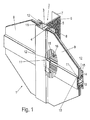
- a suspended structure 1 comprises a profile 2, which is oriented substantially vertically and has a U-shaped section 3, which has a leg with a profiling 4 for supporting an outer seal 11 and a second leg with a groove 5. At the groove 5, an inner seal 12 is retracted. Between the seals 11 and 12, a plate-shaped filling element 9 is fixed by clamping, which is formed for example as a photovoltaic module, in particular thin-film module.
- the profile 2 comprises a perpendicular to the plane of the filling elements 9 extending support web 6, which comprises an end angled portion 7.
- the support bar 6 is used for fixing to a wall, a wall adapter or on a contact plate 71 on a facade or other part of the building.
- a wing 8 is formed integrally with the leg with the groove 5 in the form of a bar, which serves for mounting a strip-shaped holder 10.
- the holder 10 is formed as a profile, which forms a U-shaped section with a first leg 13 and a second leg 14. On the first leg 13 is an outer seal 11 and on the second leg 14 is an inner seal 12 defined by a profiling or a groove.
- a web 15 is further formed, which rests on the wing 8 and is fixed there by screws 16.
- the filling element 9 is clamped at the U-shaped portion of the holder 10 between the seals 11 and 12. As a result, the filling element 9 is circumferentially fixed on all four sides between seals 11 and 12.
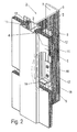
- FIG. 2 a modified embodiment of a suspended structure is shown, in which instead of the strip-shaped holder 10, which covers the gap between two filling plates 9, only an angle-shaped holder 17 is provided.
- the holder 17 is fixed by two screws 16 on the wing 8 and includes an angled portion 18 which is aligned perpendicular to the plane of the filling elements 9.
- an elastic support 19 for example made of rubber, is arranged, on which the corresponding filling element 9 is supported.
- the filling element 9 is circumferentially fixed on two sides between seals 11 and 12.
- filling elements 9 can be set on both sides of the profile 2, the profile 2 for this purpose having two U-shaped sections facing away from each other, in each of which a filling element 9 is inserted at the edge. Furthermore, several filling elements 9 can be mounted on the profile 2 in the longitudinal direction of the profile 2.
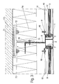
- FIG. 3 is the hanging structure of the FIG. 1 or 2 shown in a section through the profile 2.
- the profile 2 has a rearwardly projecting rear support web 6, which is fixed to a bracket mounted on the building side 70.
- a corrugation is formed on the web 6, in a corrugation engages the holder 70, wherein the corrugations are keyed by screw fillings 70 into each other.
- the holder 70 is formed in cross-section substantially T-shaped and comprises a contact plate 71 which is fixed to a wall 73 via bolts and nuts 72.
- the wall 73 may be formed, for example, concrete with appropriate anchors. Also, a determination of the holder 70 on a facade, a light roof or other structure is possible.
- an insulation 74 is provided, in which the holder 70 is arranged.
- Füflungsetti 9 are bordered at the edges and sealed between seals 11 and 12 at the U-shaped sections 3 respectively.
- the plates may, for example, form an insulation or a protection against environmental influences in order to protect the filling element 9 in the form of a photovoltaic module.
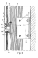
- FIG. 4 is a sectional view through the suspended structure of FIG. 1 represented in the region of the profile 10.
- the profile 2 is fixed to the support web 6 on the holder 70, wherein the profile 10 is fixed by screws 16 on the wing 8.
- the profile 10 has a hollow chamber, on the outside of which a strip-shaped cover plate 80 is mounted, which covers the gap between two adjacent filling plates 9 and on which the respective outer seals 11 are fixed. Furthermore, a spacer 32 for supporting the upper filling element 9 is arranged on the profile 10.
- FIG. 5 a modified embodiment of a hanging structure 1 'is shown in which, accordingly FIG. 2 the filling elements 9 are supported by holders 17, which are mounted on the wings 8.
- a holder 20 is mounted for lines on the right side, which may be formed integrally with the profile 2 or is defined as an additional component, for example by gluing or screwing.
- two spaced apart support webs 6 'on the profile 2' are formed, which are each fixed to a web 70 'of a carrier 71.
- the carrier 71 is mounted on a wall of a building and can thus support the profile 2 '.
- the profile 2 may be formed in different configurations, as shown in the FIGS. 6A to 6E is shown.
- FIG. 6A is a profile 2 "provided, which comprises a rectangular hollow chamber, wherein two walls of the hollow chamber forming the support webs 6" of the profile 2 "and can be mounted on a holder 70 ',
- the profile has as in the previous embodiments two U shaped sections 3, where the filling elements 9 can be inserted at the edge.
- support webs 6 'are which form no closed hollow profile, but an open hollow profile.
- a wing 8 'on the support web 6' is formed, which has a greater distance to a mounted filling element 9 than the wing 8 on the opposite side.
- other components can be mounted on the wing 8 ', which have a larger footprint.
- a closed hollow profile for the formation of support webs 6 " is provided, on which on the right side an angled wing 8" is mounted, which has a higher strength and also form a lateral surface for mounting.
- On the left side of the wing 8 is slightly curved, for example, when two adjacent filling elements 9 are to be mounted at an angle to each other.
- FIG. 6D is a further embodiment of a profile shown in which a support web 6 according to the FIGS. 1 and 2 is provided.
- the profile 2 '"again comprises two U-shaped sections 3 for fixing the filling elements 9, as shown in FIGS FIGS. 1 and 2 is shown.
- a wing 8 "'integrally a holder 20 for lines, such as electrical lines or fluid-carrying lines, integrally formed.
- a profile wings 8 are formed on opposite sides, where a screw 22 is formed.
- a V-shaped portion 21 is formed at the end of the wing 8, can be inserted into the screws for the attachment of components.
- FIG. 7A a further embodiment of a suspended structure is shown, in which a hollow profile for the formation of support webs 6 "is provided, wherein in the hollow chamber an integrally formed strip-shaped fastening element 60 is provided on both sides of the hollow profile laterally projecting wings 8 are formed, for mounting a Furthermore, a plate 31 is fastened by means of screws 16 on each wing 9.
- the U-shaped section for fixing the filling elements 9 is not formed in one piece in this exemplary embodiment, but is formed by a hollow profile with a groove 5 'for one Seal 12 and a cover strip 3 'formed with a groove 4' for an outer seal 11 '
- the cover strip 3' can be fixed by screws on the hollow profile, for this purpose on the cover strip 3 'side facing a screw 30 is formed.
- an integrally formed profile with two U-shaped sections 3 is provided for enclosing the filling elements 9, a hollow profile being provided for forming supporting webs 6 ".
- wings 8 are provided, on which holders 10 and 17 are mounted, wherein on the wing 8, a holder 20 is fixed for lines.
- the profiles 2, 2 ', 2 are preferably formed as extruded metal profiles, in particular aluminum.
- the profiles 2, 2', 2" are used in particular for the definition of photovoltaic modules on facades or roofs, whereby other structures are retrofitted with the suspended structure according to the invention can.
- the holder 17 ' may also have a prismatic or cylindrical contour instead of a winkelform, wherein it is provided with an elastic support 19.
Abstract
Description
Die vorliegende Erfindung betrifft eine Hängekonstruktion, insbesondere zur Montage an einer Fassade oder einem Dach, mit einem plattenförmigen Füllungselement, das zumindest an gegenüberliegenden Seiten an einem Profil randseitig eingefasst ist, wobei jedes Profil einen im Wesentlichen senkrecht zum Füllungselement verlaufenden Tragsteg aufweist, der an einer Unterkonstruktion festlegbar istThe present invention relates to a suspended structure, in particular for mounting on a facade or a roof, with a plate-shaped filling element, which is bordered at least on opposite sides of a profile edge, wherein each profile has a substantially perpendicular to the filling element supporting web, which on a Substructure can be specified
Es gibt Pfosten-Riegel-Konstruktionen, die als Fassaden eingesetzt werden. Hierbei werden Pfosten und Riegel aneinander befestigt und können die auftretenden Belastungen aufnehmen. Für den Einsatz von Photovoltaikmodulen sind solche Pfosten-Riegel-Konstruktionen zu aufwändig.There are mullion and transom constructions used as facades. Here, posts and bars are attached to each other and can absorb the loads occurring. For the use of photovoltaic modules such post-and-beam constructions are too complex.
Es ist daher Aufgabe der vorliegenden Erfindung, eine Hängekonstruktion zu schaffen, die auf einfache Weise die Montage von plattenförmigen Füllungselementen ermöglicht, und sowohl bei der Erstellung als auch bei der Renovierung von Fassaden montiert werden kann.It is therefore an object of the present invention to provide a suspended structure, which allows the installation of plate-shaped filling elements in a simple manner, and can be mounted both in the construction and in the renovation of facades.
Diese Aufgabe wird mit einer Hängekonstruktion mit den Merkmalen des Anspruches 1 gelöst.This object is achieved with a suspended structure with the features of claim 1.
Erfindungsgemäß ist an jedem Profil ein Flügel vorgesehen, an dem ein Halter für ein Füllungselement montiert ist. Dadurch können die Gewichtslasten durch das Füllungselement und andere Kräfte direkt über den Halter auf das Profil abgetragen werden, ohne dass eine aufwändige Verbindungskonstruktion gewählt werden muss. Der Halter kann auf einfache Weise an dem Flügel montiert, beispielsweise verschraubt, werden.According to the invention, a wing is provided on each profile, on which a holder for a filling element is mounted. As a result, the weight loads can be removed by the filling element and other forces directly on the holder on the profile without a complex connection structure must be selected. The holder can be easily mounted on the wing, for example, screwed, be.
Vorzugsweise ist der Flügel als integral mit dem Profil ausgebildete Leiste ausgebildet. Dadurch kann der Halter für das Füllungselement in beliebiger Höhe entlang der Leiste montiert werden. Zudem kann für eine stabile Abstützung der Füllungselemente auch eine Vielzahl von Befestigungsmitteln entlang des Flügels montiert werden.Preferably, the wing is formed as integrally formed with the profile bar. As a result, the holder for the filling element can be mounted at any height along the bar. In addition, a variety of fasteners along the wing can be mounted for a stable support of the filling elements.
Vorzugsweise ist an dem Profil ein U-förmiger Abschnitt ausgebildet, in den das Füllungselement randseitig eingefügt ist. Der U-förmige Abschnitt kann dabei integral mit dem Profil ausgebildet sein, das beispielsweise als metallisches Extrusionsprofiil, insbesondere aus Aluminium, ausgebildet ist. Der Flügel kann dabei als Steg parallel zur Ebene des Füllungselementes ausgebildet sein, aber auch winkelförmige Konturen des Flügels für eine höhere Festigkeit oder andere Formen sind möglich. Zudem können an dem Flügel auch weitere Bauteile, wie Halter für Leitungen, befestigt sein.Preferably, a U-shaped section is formed on the profile, in which the filling element is inserted at the edge. The U-shaped portion may be formed integrally with the profile, which is formed for example as a metallic Extrusionsprofiil, in particular aluminum. The wing may be formed as a web parallel to the plane of the filling element, but also angular contours of the wing for a higher strength or other shapes are possible. In addition, other components, such as holders for cables, can be attached to the wing.
Um mit einem Profil an gegenüberliegenden Seiten Füllungselemente festzulegen, weist jedes Profil vorzugsweise zwei U-förmige Abschnitte auf, die in unterschiedliche Richtungen ausgerichtet sind. Dadurch verringert sich die Anzahl der notwendigen Bauteile der Hängekonstruktion. Vorzugsweise ist jeweils ein Flügel auf der zum Füllungselement gewandten Seite des Tragsteges und ein U-förmiger Abschnitt an der gegenüberliegenden Seite ausgebildet. Dadurch ist das Profil im Querschnitt im Wesentlichen T-förmig ausgebildet. Statt eines Tragsteges können dabei auch mehrere Tragstege vorgesehen sein, beispielsweise auch als geschlossenes Hohlprofil. Dadurch können auch größere Gewichtslasten über das Profil abgetragen werden.In order to define filling elements with a profile on opposite sides, each profile preferably has two U-shaped sections, which are aligned in different directions. This reduces the number of necessary components of the suspended structure. Preferably, in each case a wing is formed on the side facing the filling element of the support web and a U-shaped portion on the opposite side. As a result, the profile is formed in cross-section substantially T-shaped. Instead of a support web can also be provided a plurality of support webs, for example, as a closed hollow profile. As a result, larger weight loads can be removed via the profile.
Der Halter zur Abstützung des Füllungselementes ist vorzugsweise als Winkel ausgebildet, so dass das Füllungselement nur an gegenüberliegenden Seiten in dem Profil eingefasst ist und über den Halter abgestützt wird. Für ein geschlossenes Erscheinungsbild ist es auch möglich, statt eines winkelförmigen Halters eine Leiste an dem Flügel zu montieren, die einen Spalt zwischen zwei Füllungsplatten überdeckt. Dadurch kann die Hängekonstruktion nach außen geschlossen ausgebildet werden.The holder for supporting the filling element is preferably formed as an angle, so that the filling element is bordered only on opposite sides in the profile and is supported on the holder. For a closed appearance, it is also possible to mount a strip on the wing, instead of an angle-shaped holder, which has a gap between two Covering filling plates. As a result, the suspended structure can be formed closed to the outside.
Für eine stabile Festlegung der Füllungselemente sind diese vorzugsweise randseitig zwischen zwei Dichtungen klemmend festgelegt. Die Dichtungen können dabei an entsprechenden Schenkeln des Profils montiert sein. Als Füllungselemente werden vorzugsweise Photovoltaikmodule eingesetzt, die über die Hängekonstruktion an einer Fassade oder einem Dach montiert werden.For a stable fixing of the filling elements, these are preferably fixed in a clamping manner on the edge side between two seals. The seals can be mounted on corresponding legs of the profile. As filling elements photovoltaic modules are preferably used, which are mounted on the hanging structure on a facade or a roof.
Die Erfindung wird nachfolgend anhand mehrerer Ausführungsbeispiele mit Bezug auf die beigefügten Zeichnungen näher erläutert. Es zeigen:
- Figur 1
- eine perspektivische Ansicht einer erfindungsgemäßen Hängekonstruktion;
Figur 2- eine perspektivische Ansicht einer modifizierten Hängekonstruktion;
Figur 3- eine Schnittansicht durch die Hängekonstruktion der
Figur 1 ; Figur 4- eine Schnittansicht durch die Hängekonstruktion der
Figur 1 ; Figur 5- eine Schnittansicht durch eine modifizierte Hängekonstruktion;
- Figuren 6A bis 6E
- mehrere Querschnittsansichten von Profilen für eine erfindungsgemäße Hängekonstruktion, und
- Figuren 7A und 7B
- zwei Beispiele für modifizierte Hängekonstruktionen.
- FIG. 1
- a perspective view of a suspended structure according to the invention;
- FIG. 2
- a perspective view of a modified suspension construction;
- FIG. 3
- a sectional view through the hanging structure of
FIG. 1 ; - FIG. 4
- a sectional view through the hanging structure of
FIG. 1 ; - FIG. 5
- a sectional view through a modified suspension structure;
- FIGS. 6A to 6E
- several cross-sectional views of profiles for a suspension construction according to the invention, and
- FIGS. 7A and 7B
- two examples of modified suspended structures.
Eine Hängekonstruktion 1 umfasst ein Profil 2, das im Wesentlichen vertikal ausgerichtet ist und einen U-förmigen Abschnitt 3 aufweist, der einen Schenkel mit einer Profilierung 4 zur Abstützung einer äußeren Dichtung 11 sowie einen zweiten Schenkel mit einer Nut 5 aufweist. An der Nut 5 ist eine innere Dichtung 12 eingezogen. Zwischen den Dichtungen 11 und 12 ist ein plattenförmiges Füllungselement 9 klemmend festgelegt, das beispielsweise als Photovoltaikmodul, insbesondere Dünnschichtmodul, ausgebildet ist.A suspended structure 1 comprises a
Das Profil 2 umfasst einen senkrecht zur Ebene der Füllungselemente 9 verlaufenden Tragsteg 6, der einen endseitig abgewinkelten Abschnitt 7 umfasst. Der Tragsteg 6 dient zur Fixierung an einer Wand, einem Wandadapter oder an einer Anlageplatte 71 an einer Fassade oder einem anderem Gebäudeteil.The
An dem Profil 2 ist integral mit dem Schenkel mit der Nut 5 ein Flügel 8 in Form einer Leiste ausgebildet, die zur Montage eines leistenförmigen Halters 10 dient. Der Halter 10 ist als Profil ausgebildet, das einen U-förmigen Abschnitt mit einem ersten Schenkel 13 und einem zweiten Schenkel 14 ausbildet. An dem ersten Schenkel 13 ist eine äußere Dichtung 11 und an dem zweiten Schenkel 14 ist eine innere Dichtung 12 über eine Profilierung bzw. eine Nut festgelegt. An dem Halter 10 ist ferner ein Steg 15 ausgebildet, der auf dem Flügel 8 aufliegt und dort über Schrauben 16 festgelegt ist. Das Füllungselement 9 ist an dem U-förmigen Abschnitt des Halters 10 zwischen den Dichtungen 11 und 12 eingeklemmt. Dadurch ist das Füllungselement 9 umlaufend an allen vier Seiten zwischen Dichtungen 11 und 12 festgelegt.On the
In
Wie in den
In
An dem Profil 2 sind an den U-förmigen Abschnitten 3 jeweils Füflungselemente 9 randseitig eingefasst und zwischen Dichtungen 11 und 12 eingeklemmt. An dem Flügel 8 sind zusätzlich zu einem Halter 17, 17', optional auch Platten (nicht dargestellt) oder Profile 10 über Schrauben 16 festgelegt. Die Platten können beispielsweise eine Isolierung oder einen Schutz vor Umgebungseinflüssen ausbilden, um das Füllungselement 9 in Form eines Photovoltaikmoduls zu schützen.At the
In
In
Bei dem in
Bei der Hängekonstruktion kann das Profil 2 in unterschiedlichen Ausgestaltungen ausgebildet sein, wie dies in den
Bei dem Ausführungsbeispiel der
Bei dem in
Bei dem in
In
Bei dem im
In
In dem in
Die Profile 2, 2', 2" sind vorzugsweise als extrudierte Metallprofile ausgebildet, insbesondere aus Aluminium. Die Profile 2, 2', 2" dienen insbesondere zur Festlegung von Photovoltaikmodulen an Fassaden oder Dächern, wobei auch andere Bauwerke mit der erfindungsgemäßen Hängekonstruktion nachgerüstet werden können.The
Der Halter 17' kann statt einer winkelform auch eine prismatische oder zylindrische Kontur besitzen, wobei er mit einer elastischen Auflage 19 versehen ist. Die Anbindung an den Flügel erfolgt über Schrauben und/oder form-, kraft- und/oder formschlüssige Verbindungsmittel.The holder 17 'may also have a prismatic or cylindrical contour instead of a winkelform, wherein it is provided with an
Claims (15)
Applications Claiming Priority (1)
| Application Number | Priority Date | Filing Date | Title |
|---|---|---|---|
| DE202010005492U DE202010005492U1 (en) | 2010-05-25 | 2010-05-25 | suspended construction |
Publications (3)
| Publication Number | Publication Date |
|---|---|
| EP2390432A2 true EP2390432A2 (en) | 2011-11-30 |
| EP2390432A3 EP2390432A3 (en) | 2012-02-22 |
| EP2390432B1 EP2390432B1 (en) | 2014-03-26 |
Family
ID=42814076
Family Applications (1)
| Application Number | Title | Priority Date | Filing Date |
|---|---|---|---|
| EP11167058.4A Active EP2390432B1 (en) | 2010-05-25 | 2011-05-23 | Suspended construction |
Country Status (2)
| Country | Link |
|---|---|
| EP (1) | EP2390432B1 (en) |
| DE (1) | DE202010005492U1 (en) |
Cited By (1)
| Publication number | Priority date | Publication date | Assignee | Title |
|---|---|---|---|---|
| US8991121B1 (en) * | 2013-05-23 | 2015-03-31 | Baker Metal Products, Inc. | Thermally improved curtain wall connection system |
Families Citing this family (5)
| Publication number | Priority date | Publication date | Assignee | Title |
|---|---|---|---|---|
| DE102014011705A1 (en) * | 2014-08-07 | 2016-02-11 | Jasmin Fischer | Photovoltaic (PV) facade systems with phase change materials (PCM) - PV-PCM facades |
| US10673373B2 (en) | 2016-02-12 | 2020-06-02 | Solarcity Corporation | Building integrated photovoltaic roofing assemblies and associated systems and methods |
| EP3409862B1 (en) * | 2017-05-30 | 2020-04-08 | Voestalpine Sadef NV | An assembly adapted to support panels |
| CH717550A1 (en) * | 2020-06-18 | 2021-12-30 | Rene Schmid | PV module facade construction for integration into existing facade surfaces. |
| AT17697U3 (en) * | 2022-02-09 | 2023-04-15 | Kremser Ing Helmut | component holder |
Family Cites Families (5)
| Publication number | Priority date | Publication date | Assignee | Title |
|---|---|---|---|---|
| US3734550A (en) * | 1971-09-16 | 1973-05-22 | Engineered Products Inc | Building construction assembly |
| US4936065A (en) * | 1989-01-17 | 1990-06-26 | Dunmon Corporation | Non-foldable composite attachment system |
| US5245808A (en) * | 1989-12-01 | 1993-09-21 | Kawneer Company, Inc. | Retainer and weatherseal for structurally bonded glazing |
| DE10024168C1 (en) * | 2000-05-17 | 2002-01-31 | Rp Technik Gmbh | Fastening arrangement, for facing module, has pressure plate provided centrally on outer face of substructure to act upon edge of holder section and by spring element located in holding position enabling clipping-in of facing module |
| DE20010299U1 (en) * | 2000-06-08 | 2000-11-16 | Schueco Int Kg | Facade and / or light roof construction and mounting device for fastening solar panels to a facade and / or light roof construction |
-
2010
- 2010-05-25 DE DE202010005492U patent/DE202010005492U1/en not_active Expired - Lifetime
-
2011
- 2011-05-23 EP EP11167058.4A patent/EP2390432B1/en active Active
Non-Patent Citations (1)
| Title |
|---|
| None |
Cited By (1)
| Publication number | Priority date | Publication date | Assignee | Title |
|---|---|---|---|---|
| US8991121B1 (en) * | 2013-05-23 | 2015-03-31 | Baker Metal Products, Inc. | Thermally improved curtain wall connection system |
Also Published As
| Publication number | Publication date |
|---|---|
| EP2390432A3 (en) | 2012-02-22 |
| EP2390432B1 (en) | 2014-03-26 |
| DE202010005492U1 (en) | 2010-09-30 |
Similar Documents
| Publication | Publication Date | Title |
|---|---|---|
| EP2390432B1 (en) | Suspended construction | |
| EP2174074A1 (en) | Assembly frame for the integrated mounting of photovoltaic modules and solar collectors on buildings | |
| EP2238393A2 (en) | Solar module fastening system | |
| DE202008002264U1 (en) | Holding device for plate-shaped elements | |
| EP3245344B1 (en) | Post-beam construction | |
| WO2016198305A1 (en) | Photovoltaic module assembly bracket, and photovoltaic system | |
| DE3812223C2 (en) | ||
| EP3365510B1 (en) | Arrangement for wall, ceiling, or roof cladding of a building structure | |
| DE202011100947U1 (en) | Device for fixing photovoltaic modules on a flat roof | |
| EP2670927A1 (en) | Fastening arrangement for glass balustrades | |
| EP0298328B1 (en) | Façade wall | |
| AT10386U1 (en) | PARTITION SYSTEM | |
| DE102008055953A1 (en) | Integrated roof system, attachment of insert profiles on sandwich panels with undercut grooves | |
| EP1582643A2 (en) | Mullion-Transom system with less visible supports | |
| DE202016105087U1 (en) | Retaining rail for a French balcony as well as holding device and arrangement for it | |
| DE202012101578U1 (en) | roof hook | |
| DE102017125674B4 (en) | Holding device for a surface element, fall protection and French balcony | |
| DE202007003873U1 (en) | Sealing profile for use in crossbar-pile construction for angular glazing and vertical facade, has web exhibiting reference rip line that lies between center part and web, so that web is completely removable from center part | |
| EP2447621A1 (en) | Stand system for mounting solar modules | |
| EP2224078B1 (en) | Construction kit for producing canopies | |
| DE202013100602U1 (en) | Flood protection system for building openings | |
| EP3323954B1 (en) | Post and crossmember structure | |
| EP2436848A2 (en) | Support structure | |
| DE202016001119U1 (en) | Arrangement for fixing plate-shaped components to walls and roofs of buildings | |
| DE102008013263A1 (en) | Attachment system for plate shaped element of slanting roof covered with roof slabs, has side unit on lower surface of plate shaped element, where prominent attachment bars are provided |
Legal Events
| Date | Code | Title | Description |
|---|---|---|---|
| AK | Designated contracting states |
Kind code of ref document: A2 Designated state(s): AL AT BE BG CH CY CZ DE DK EE ES FI FR GB GR HR HU IE IS IT LI LT LU LV MC MK MT NL NO PL PT RO RS SE SI SK SM TR |
|
| AX | Request for extension of the european patent |
Extension state: BA ME |
|
| PUAI | Public reference made under article 153(3) epc to a published international application that has entered the european phase |
Free format text: ORIGINAL CODE: 0009012 |
|
| PUAL | Search report despatched |
Free format text: ORIGINAL CODE: 0009013 |
|
| AK | Designated contracting states |
Kind code of ref document: A3 Designated state(s): AL AT BE BG CH CY CZ DE DK EE ES FI FR GB GR HR HU IE IS IT LI LT LU LV MC MK MT NL NO PL PT RO RS SE SI SK SM TR |
|
| AX | Request for extension of the european patent |
Extension state: BA ME |
|
| RIC1 | Information provided on ipc code assigned before grant |
Ipc: F24J 2/52 20060101ALN20120116BHEP Ipc: E06B 3/54 20060101ALI20120116BHEP Ipc: E04B 2/96 20060101AFI20120116BHEP |
|
| 17P | Request for examination filed |
Effective date: 20120210 |
|
| 17Q | First examination report despatched |
Effective date: 20130128 |
|
| GRAP | Despatch of communication of intention to grant a patent |
Free format text: ORIGINAL CODE: EPIDOSNIGR1 |
|
| RIC1 | Information provided on ipc code assigned before grant |
Ipc: E06B 3/54 20060101ALI20131001BHEP Ipc: E04B 2/96 20060101AFI20131001BHEP Ipc: F24J 2/52 20060101ALN20131001BHEP |
|
| INTG | Intention to grant announced |
Effective date: 20131015 |
|
| GRAS | Grant fee paid |
Free format text: ORIGINAL CODE: EPIDOSNIGR3 |
|
| GRAA | (expected) grant |
Free format text: ORIGINAL CODE: 0009210 |
|
| AK | Designated contracting states |
Kind code of ref document: B1 Designated state(s): AL AT BE BG CH CY CZ DE DK EE ES FI FR GB GR HR HU IE IS IT LI LT LU LV MC MK MT NL NO PL PT RO RS SE SI SK SM TR |
|
| REG | Reference to a national code |
Ref country code: GB Ref legal event code: FG4D Free format text: NOT ENGLISH |
|
| REG | Reference to a national code |
Ref country code: CH Ref legal event code: EP |
|
| REG | Reference to a national code |
Ref country code: AT Ref legal event code: REF Ref document number: 659101 Country of ref document: AT Kind code of ref document: T Effective date: 20140415 |
|
| REG | Reference to a national code |
Ref country code: IE Ref legal event code: FG4D Free format text: LANGUAGE OF EP DOCUMENT: GERMAN |
|
| REG | Reference to a national code |
Ref country code: DE Ref legal event code: R096 Ref document number: 502011002516 Country of ref document: DE Effective date: 20140508 |
|
| PG25 | Lapsed in a contracting state [announced via postgrant information from national office to epo] |
Ref country code: LT Free format text: LAPSE BECAUSE OF FAILURE TO SUBMIT A TRANSLATION OF THE DESCRIPTION OR TO PAY THE FEE WITHIN THE PRESCRIBED TIME-LIMIT Effective date: 20140326 Ref country code: NO Free format text: LAPSE BECAUSE OF FAILURE TO SUBMIT A TRANSLATION OF THE DESCRIPTION OR TO PAY THE FEE WITHIN THE PRESCRIBED TIME-LIMIT Effective date: 20140626 |
|
| REG | Reference to a national code |
Ref country code: CH Ref legal event code: NV Representative=s name: ISLER AND PEDRAZZINI AG, CH |
|
| REG | Reference to a national code |
Ref country code: NL Ref legal event code: VDEP Effective date: 20140326 |
|
| REG | Reference to a national code |
Ref country code: LT Ref legal event code: MG4D |
|
| PG25 | Lapsed in a contracting state [announced via postgrant information from national office to epo] |
Ref country code: SE Free format text: LAPSE BECAUSE OF FAILURE TO SUBMIT A TRANSLATION OF THE DESCRIPTION OR TO PAY THE FEE WITHIN THE PRESCRIBED TIME-LIMIT Effective date: 20140326 Ref country code: FI Free format text: LAPSE BECAUSE OF FAILURE TO SUBMIT A TRANSLATION OF THE DESCRIPTION OR TO PAY THE FEE WITHIN THE PRESCRIBED TIME-LIMIT Effective date: 20140326 |
|
| PG25 | Lapsed in a contracting state [announced via postgrant information from national office to epo] |
Ref country code: RS Free format text: LAPSE BECAUSE OF FAILURE TO SUBMIT A TRANSLATION OF THE DESCRIPTION OR TO PAY THE FEE WITHIN THE PRESCRIBED TIME-LIMIT Effective date: 20140326 Ref country code: HR Free format text: LAPSE BECAUSE OF FAILURE TO SUBMIT A TRANSLATION OF THE DESCRIPTION OR TO PAY THE FEE WITHIN THE PRESCRIBED TIME-LIMIT Effective date: 20140326 Ref country code: LV Free format text: LAPSE BECAUSE OF FAILURE TO SUBMIT A TRANSLATION OF THE DESCRIPTION OR TO PAY THE FEE WITHIN THE PRESCRIBED TIME-LIMIT Effective date: 20140326 |
|
| PG25 | Lapsed in a contracting state [announced via postgrant information from national office to epo] |
Ref country code: EE Free format text: LAPSE BECAUSE OF FAILURE TO SUBMIT A TRANSLATION OF THE DESCRIPTION OR TO PAY THE FEE WITHIN THE PRESCRIBED TIME-LIMIT Effective date: 20140326 Ref country code: RO Free format text: LAPSE BECAUSE OF FAILURE TO SUBMIT A TRANSLATION OF THE DESCRIPTION OR TO PAY THE FEE WITHIN THE PRESCRIBED TIME-LIMIT Effective date: 20140326 Ref country code: CZ Free format text: LAPSE BECAUSE OF FAILURE TO SUBMIT A TRANSLATION OF THE DESCRIPTION OR TO PAY THE FEE WITHIN THE PRESCRIBED TIME-LIMIT Effective date: 20140326 Ref country code: BG Free format text: LAPSE BECAUSE OF FAILURE TO SUBMIT A TRANSLATION OF THE DESCRIPTION OR TO PAY THE FEE WITHIN THE PRESCRIBED TIME-LIMIT Effective date: 20140626 Ref country code: CY Free format text: LAPSE BECAUSE OF FAILURE TO SUBMIT A TRANSLATION OF THE DESCRIPTION OR TO PAY THE FEE WITHIN THE PRESCRIBED TIME-LIMIT Effective date: 20140326 Ref country code: IS Free format text: LAPSE BECAUSE OF FAILURE TO SUBMIT A TRANSLATION OF THE DESCRIPTION OR TO PAY THE FEE WITHIN THE PRESCRIBED TIME-LIMIT Effective date: 20140726 Ref country code: NL Free format text: LAPSE BECAUSE OF FAILURE TO SUBMIT A TRANSLATION OF THE DESCRIPTION OR TO PAY THE FEE WITHIN THE PRESCRIBED TIME-LIMIT Effective date: 20140326 |
|
| PG25 | Lapsed in a contracting state [announced via postgrant information from national office to epo] |
Ref country code: ES Free format text: LAPSE BECAUSE OF FAILURE TO SUBMIT A TRANSLATION OF THE DESCRIPTION OR TO PAY THE FEE WITHIN THE PRESCRIBED TIME-LIMIT Effective date: 20140326 Ref country code: PL Free format text: LAPSE BECAUSE OF FAILURE TO SUBMIT A TRANSLATION OF THE DESCRIPTION OR TO PAY THE FEE WITHIN THE PRESCRIBED TIME-LIMIT Effective date: 20140326 Ref country code: SK Free format text: LAPSE BECAUSE OF FAILURE TO SUBMIT A TRANSLATION OF THE DESCRIPTION OR TO PAY THE FEE WITHIN THE PRESCRIBED TIME-LIMIT Effective date: 20140326 |
|
| PG25 | Lapsed in a contracting state [announced via postgrant information from national office to epo] |
Ref country code: LU Free format text: LAPSE BECAUSE OF FAILURE TO SUBMIT A TRANSLATION OF THE DESCRIPTION OR TO PAY THE FEE WITHIN THE PRESCRIBED TIME-LIMIT Effective date: 20140523 Ref country code: PT Free format text: LAPSE BECAUSE OF FAILURE TO SUBMIT A TRANSLATION OF THE DESCRIPTION OR TO PAY THE FEE WITHIN THE PRESCRIBED TIME-LIMIT Effective date: 20140728 |
|
| REG | Reference to a national code |
Ref country code: DE Ref legal event code: R097 Ref document number: 502011002516 Country of ref document: DE |
|
| PG25 | Lapsed in a contracting state [announced via postgrant information from national office to epo] |
Ref country code: DK Free format text: LAPSE BECAUSE OF FAILURE TO SUBMIT A TRANSLATION OF THE DESCRIPTION OR TO PAY THE FEE WITHIN THE PRESCRIBED TIME-LIMIT Effective date: 20140326 Ref country code: MC Free format text: LAPSE BECAUSE OF FAILURE TO SUBMIT A TRANSLATION OF THE DESCRIPTION OR TO PAY THE FEE WITHIN THE PRESCRIBED TIME-LIMIT Effective date: 20140326 |
|
| PLBE | No opposition filed within time limit |
Free format text: ORIGINAL CODE: 0009261 |
|
| STAA | Information on the status of an ep patent application or granted ep patent |
Free format text: STATUS: NO OPPOSITION FILED WITHIN TIME LIMIT |
|
| REG | Reference to a national code |
Ref country code: IE Ref legal event code: MM4A |
|
| 26N | No opposition filed |
Effective date: 20150106 |
|
| REG | Reference to a national code |
Ref country code: DE Ref legal event code: R097 Ref document number: 502011002516 Country of ref document: DE Effective date: 20150106 |
|
| PG25 | Lapsed in a contracting state [announced via postgrant information from national office to epo] |
Ref country code: IE Free format text: LAPSE BECAUSE OF NON-PAYMENT OF DUE FEES Effective date: 20140523 |
|
| PG25 | Lapsed in a contracting state [announced via postgrant information from national office to epo] |
Ref country code: SI Free format text: LAPSE BECAUSE OF FAILURE TO SUBMIT A TRANSLATION OF THE DESCRIPTION OR TO PAY THE FEE WITHIN THE PRESCRIBED TIME-LIMIT Effective date: 20140326 |
|
| PG25 | Lapsed in a contracting state [announced via postgrant information from national office to epo] |
Ref country code: MT Free format text: LAPSE BECAUSE OF FAILURE TO SUBMIT A TRANSLATION OF THE DESCRIPTION OR TO PAY THE FEE WITHIN THE PRESCRIBED TIME-LIMIT Effective date: 20140326 |
|
| PG25 | Lapsed in a contracting state [announced via postgrant information from national office to epo] |
Ref country code: SM Free format text: LAPSE BECAUSE OF FAILURE TO SUBMIT A TRANSLATION OF THE DESCRIPTION OR TO PAY THE FEE WITHIN THE PRESCRIBED TIME-LIMIT Effective date: 20140326 |
|
| REG | Reference to a national code |
Ref country code: FR Ref legal event code: PLFP Year of fee payment: 6 |
|
| PG25 | Lapsed in a contracting state [announced via postgrant information from national office to epo] |
Ref country code: GR Free format text: LAPSE BECAUSE OF FAILURE TO SUBMIT A TRANSLATION OF THE DESCRIPTION OR TO PAY THE FEE WITHIN THE PRESCRIBED TIME-LIMIT Effective date: 20140627 |
|
| PG25 | Lapsed in a contracting state [announced via postgrant information from national office to epo] |
Ref country code: BE Free format text: LAPSE BECAUSE OF FAILURE TO SUBMIT A TRANSLATION OF THE DESCRIPTION OR TO PAY THE FEE WITHIN THE PRESCRIBED TIME-LIMIT Effective date: 20140531 Ref country code: HU Free format text: LAPSE BECAUSE OF FAILURE TO SUBMIT A TRANSLATION OF THE DESCRIPTION OR TO PAY THE FEE WITHIN THE PRESCRIBED TIME-LIMIT; INVALID AB INITIO Effective date: 20110523 Ref country code: TR Free format text: LAPSE BECAUSE OF FAILURE TO SUBMIT A TRANSLATION OF THE DESCRIPTION OR TO PAY THE FEE WITHIN THE PRESCRIBED TIME-LIMIT Effective date: 20140326 |
|
| PGFP | Annual fee paid to national office [announced via postgrant information from national office to epo] |
Ref country code: CH Payment date: 20160526 Year of fee payment: 6 Ref country code: GB Payment date: 20160523 Year of fee payment: 6 |
|
| PGFP | Annual fee paid to national office [announced via postgrant information from national office to epo] |
Ref country code: IT Payment date: 20160524 Year of fee payment: 6 Ref country code: AT Payment date: 20160519 Year of fee payment: 6 Ref country code: FR Payment date: 20160523 Year of fee payment: 6 |
|
| REG | Reference to a national code |
Ref country code: CH Ref legal event code: PL |
|
| REG | Reference to a national code |
Ref country code: AT Ref legal event code: MM01 Ref document number: 659101 Country of ref document: AT Kind code of ref document: T Effective date: 20170523 |
|
| GBPC | Gb: european patent ceased through non-payment of renewal fee |
Effective date: 20170523 |
|
| PG25 | Lapsed in a contracting state [announced via postgrant information from national office to epo] |
Ref country code: AT Free format text: LAPSE BECAUSE OF NON-PAYMENT OF DUE FEES Effective date: 20170523 |
|
| PG25 | Lapsed in a contracting state [announced via postgrant information from national office to epo] |
Ref country code: CH Free format text: LAPSE BECAUSE OF NON-PAYMENT OF DUE FEES Effective date: 20170531 Ref country code: LI Free format text: LAPSE BECAUSE OF NON-PAYMENT OF DUE FEES Effective date: 20170531 |
|
| REG | Reference to a national code |
Ref country code: FR Ref legal event code: ST Effective date: 20180131 |
|
| PG25 | Lapsed in a contracting state [announced via postgrant information from national office to epo] |
Ref country code: GB Free format text: LAPSE BECAUSE OF NON-PAYMENT OF DUE FEES Effective date: 20170523 |
|
| PG25 | Lapsed in a contracting state [announced via postgrant information from national office to epo] |
Ref country code: IT Free format text: LAPSE BECAUSE OF NON-PAYMENT OF DUE FEES Effective date: 20170523 Ref country code: FR Free format text: LAPSE BECAUSE OF NON-PAYMENT OF DUE FEES Effective date: 20170531 |
|
| PG25 | Lapsed in a contracting state [announced via postgrant information from national office to epo] |
Ref country code: MK Free format text: LAPSE BECAUSE OF FAILURE TO SUBMIT A TRANSLATION OF THE DESCRIPTION OR TO PAY THE FEE WITHIN THE PRESCRIBED TIME-LIMIT Effective date: 20140326 |
|
| PG25 | Lapsed in a contracting state [announced via postgrant information from national office to epo] |
Ref country code: AL Free format text: LAPSE BECAUSE OF FAILURE TO SUBMIT A TRANSLATION OF THE DESCRIPTION OR TO PAY THE FEE WITHIN THE PRESCRIBED TIME-LIMIT Effective date: 20140326 |
|
| PGFP | Annual fee paid to national office [announced via postgrant information from national office to epo] |
Ref country code: DE Payment date: 20230627 Year of fee payment: 13 |
|
| P01 | Opt-out of the competence of the unified patent court (upc) registered |
Effective date: 20230813 |