EP2390120A1 - Akustische Entkopplung in Fahrzeugfahrwerken - Google Patents
Akustische Entkopplung in Fahrzeugfahrwerken Download PDFInfo
- Publication number
- EP2390120A1 EP2390120A1 EP11164537A EP11164537A EP2390120A1 EP 2390120 A1 EP2390120 A1 EP 2390120A1 EP 11164537 A EP11164537 A EP 11164537A EP 11164537 A EP11164537 A EP 11164537A EP 2390120 A1 EP2390120 A1 EP 2390120A1
- Authority
- EP
- European Patent Office
- Prior art keywords
- strut
- damping
- chassis
- radhausdom
- intermediate layers
- Prior art date
- Legal status (The legal status is an assumption and is not a legal conclusion. Google has not performed a legal analysis and makes no representation as to the accuracy of the status listed.)
- Granted
Links
- 239000000463 material Substances 0.000 claims abstract description 19
- 230000009365 direct transmission Effects 0.000 claims abstract description 6
- 238000013016 damping Methods 0.000 claims description 25
- 239000002184 metal Substances 0.000 claims description 14
- 229910052751 metal Inorganic materials 0.000 claims description 14
- 239000000725 suspension Substances 0.000 claims description 13
- 150000002739 metals Chemical class 0.000 claims description 12
- 229920001971 elastomer Polymers 0.000 claims description 4
- 239000000806 elastomer Substances 0.000 claims description 2
- 239000006096 absorbing agent Substances 0.000 abstract description 5
- 230000035939 shock Effects 0.000 abstract description 5
- 238000005096 rolling process Methods 0.000 description 6
- 230000005540 biological transmission Effects 0.000 description 4
- 229910000831 Steel Inorganic materials 0.000 description 3
- 229920002635 polyurethane Polymers 0.000 description 3
- 239000004814 polyurethane Substances 0.000 description 3
- 239000010959 steel Substances 0.000 description 3
- 229920005830 Polyurethane Foam Polymers 0.000 description 2
- 230000006978 adaptation Effects 0.000 description 2
- 239000011496 polyurethane foam Substances 0.000 description 2
- 239000005060 rubber Substances 0.000 description 2
- 239000003190 viscoelastic substance Substances 0.000 description 2
- OKTJSMMVPCPJKN-UHFFFAOYSA-N Carbon Chemical compound [C] OKTJSMMVPCPJKN-UHFFFAOYSA-N 0.000 description 1
- 229910001018 Cast iron Inorganic materials 0.000 description 1
- 230000002238 attenuated effect Effects 0.000 description 1
- 230000007547 defect Effects 0.000 description 1
- 229910002804 graphite Inorganic materials 0.000 description 1
- 239000010439 graphite Substances 0.000 description 1
- 238000004519 manufacturing process Methods 0.000 description 1
- 239000004033 plastic Substances 0.000 description 1
- 229920003023 plastic Polymers 0.000 description 1
Images


Classifications
-
- B—PERFORMING OPERATIONS; TRANSPORTING
- B60—VEHICLES IN GENERAL
- B60G—VEHICLE SUSPENSION ARRANGEMENTS
- B60G15/00—Resilient suspensions characterised by arrangement, location or type of combined spring and vibration damper, e.g. telescopic type
- B60G15/08—Resilient suspensions characterised by arrangement, location or type of combined spring and vibration damper, e.g. telescopic type having fluid spring
- B60G15/12—Resilient suspensions characterised by arrangement, location or type of combined spring and vibration damper, e.g. telescopic type having fluid spring and fluid damper
-
- B—PERFORMING OPERATIONS; TRANSPORTING
- B32—LAYERED PRODUCTS
- B32B—LAYERED PRODUCTS, i.e. PRODUCTS BUILT-UP OF STRATA OF FLAT OR NON-FLAT, e.g. CELLULAR OR HONEYCOMB, FORM
- B32B1/00—Layered products having a non-planar shape
-
- B—PERFORMING OPERATIONS; TRANSPORTING
- B32—LAYERED PRODUCTS
- B32B—LAYERED PRODUCTS, i.e. PRODUCTS BUILT-UP OF STRATA OF FLAT OR NON-FLAT, e.g. CELLULAR OR HONEYCOMB, FORM
- B32B15/00—Layered products comprising a layer of metal
- B32B15/04—Layered products comprising a layer of metal comprising metal as the main or only constituent of a layer, which is next to another layer of the same or of a different material
- B32B15/06—Layered products comprising a layer of metal comprising metal as the main or only constituent of a layer, which is next to another layer of the same or of a different material of natural rubber or synthetic rubber
-
- B—PERFORMING OPERATIONS; TRANSPORTING
- B32—LAYERED PRODUCTS
- B32B—LAYERED PRODUCTS, i.e. PRODUCTS BUILT-UP OF STRATA OF FLAT OR NON-FLAT, e.g. CELLULAR OR HONEYCOMB, FORM
- B32B15/00—Layered products comprising a layer of metal
- B32B15/04—Layered products comprising a layer of metal comprising metal as the main or only constituent of a layer, which is next to another layer of the same or of a different material
- B32B15/08—Layered products comprising a layer of metal comprising metal as the main or only constituent of a layer, which is next to another layer of the same or of a different material of synthetic resin
-
- B—PERFORMING OPERATIONS; TRANSPORTING
- B32—LAYERED PRODUCTS
- B32B—LAYERED PRODUCTS, i.e. PRODUCTS BUILT-UP OF STRATA OF FLAT OR NON-FLAT, e.g. CELLULAR OR HONEYCOMB, FORM
- B32B25/00—Layered products comprising a layer of natural or synthetic rubber
- B32B25/04—Layered products comprising a layer of natural or synthetic rubber comprising rubber as the main or only constituent of a layer, which is next to another layer of the same or of a different material
-
- B—PERFORMING OPERATIONS; TRANSPORTING
- B32—LAYERED PRODUCTS
- B32B—LAYERED PRODUCTS, i.e. PRODUCTS BUILT-UP OF STRATA OF FLAT OR NON-FLAT, e.g. CELLULAR OR HONEYCOMB, FORM
- B32B27/00—Layered products comprising a layer of synthetic resin
- B32B27/06—Layered products comprising a layer of synthetic resin as the main or only constituent of a layer, which is next to another layer of the same or of a different material
-
- B—PERFORMING OPERATIONS; TRANSPORTING
- B32—LAYERED PRODUCTS
- B32B—LAYERED PRODUCTS, i.e. PRODUCTS BUILT-UP OF STRATA OF FLAT OR NON-FLAT, e.g. CELLULAR OR HONEYCOMB, FORM
- B32B27/00—Layered products comprising a layer of synthetic resin
- B32B27/40—Layered products comprising a layer of synthetic resin comprising polyurethanes
-
- B—PERFORMING OPERATIONS; TRANSPORTING
- B32—LAYERED PRODUCTS
- B32B—LAYERED PRODUCTS, i.e. PRODUCTS BUILT-UP OF STRATA OF FLAT OR NON-FLAT, e.g. CELLULAR OR HONEYCOMB, FORM
- B32B2307/00—Properties of the layers or laminate
- B32B2307/10—Properties of the layers or laminate having particular acoustical properties
- B32B2307/102—Insulating
-
- B—PERFORMING OPERATIONS; TRANSPORTING
- B60—VEHICLES IN GENERAL
- B60G—VEHICLE SUSPENSION ARRANGEMENTS
- B60G2202/00—Indexing codes relating to the type of spring, damper or actuator
- B60G2202/10—Type of spring
- B60G2202/15—Fluid spring
- B60G2202/152—Pneumatic spring
-
- B—PERFORMING OPERATIONS; TRANSPORTING
- B60—VEHICLES IN GENERAL
- B60G—VEHICLE SUSPENSION ARRANGEMENTS
- B60G2202/00—Indexing codes relating to the type of spring, damper or actuator
- B60G2202/30—Spring/Damper and/or actuator Units
- B60G2202/31—Spring/Damper and/or actuator Units with the spring arranged around the damper, e.g. MacPherson strut
- B60G2202/314—The spring being a pneumatic spring
-
- B—PERFORMING OPERATIONS; TRANSPORTING
- B60—VEHICLES IN GENERAL
- B60G—VEHICLE SUSPENSION ARRANGEMENTS
- B60G2204/00—Indexing codes related to suspensions per se or to auxiliary parts
- B60G2204/10—Mounting of suspension elements
- B60G2204/12—Mounting of springs or dampers
- B60G2204/126—Mounting of pneumatic springs
-
- B—PERFORMING OPERATIONS; TRANSPORTING
- B60—VEHICLES IN GENERAL
- B60G—VEHICLE SUSPENSION ARRANGEMENTS
- B60G2206/00—Indexing codes related to the manufacturing of suspensions: constructional features, the materials used, procedures or tools
- B60G2206/01—Constructional features of suspension elements, e.g. arms, dampers, springs
- B60G2206/70—Materials used in suspensions
- B60G2206/73—Rubber; Elastomers
Definitions
- the invention relates to a vehicle chassis, with a supported by a strut wheel, the strut clamped between the chassis and body and is provided with a spring and a damping device for suspension and damping of the body movements, in which at least the connection between the body and strut with a Intermediate layer is provided, which has acoustically damping materials.
- Struts with steel springs or air springs are used today, especially in passenger cars as a particularly comfortable suspension elements and ensure a pleasant Fahrgefiihl. This is the case in particular with air springs, which can be adjusted depending on the road conditions.
- An air spring system or level control system consists of the air spring and the damping device comprehensive air spring struts for each wheel or at least for each axis, from the air supply system with a compressor, a memory, a regenerable dryer, and from other switchable or permanently set pneumatic controls and points to in usually an electronic control on.
- Air springs which are clamped between the chassis and body and having an air spring bellows, which in turn are mounted between a usually body-side air spring cover and a chassis-side rolling piston, the expert knows in a variety of versions.
- the air spring is in operation under one internal overpressure.
- the air spring bellows rolls under load and during spring movements to form a rolled fold on the outer contour of a concentric component, usually on the air spring piston / rolling piston.
- Such air spring is often used in road or rail vehicles to achieve a comfortable suspension.
- the air bag is associated with a damping device, namely either a hydraulic shock absorber or an air damping, which is integrated in the air suspension, ie a so-called "air spring damper unit".
- air springs in which the air bag forms only one side of a roll fold, namely usually on the rolling piston, as well as air springs, in which the rolling bellows is clamped to form a two-sided (rolling) fold between the air spring cover and rolling piston.
- Air springs with unilateral roll folds are often found in passenger cars, while the often larger and more sustainable air springs with roll creases on both sides are more likely to be installed in trucks and rail vehicles.
- So for the invention was the task of providing sufficient acoustic decoupling at critical points, without affecting the driving dynamics significantly, for example, in the rear seats of a sedan, where the connection points of the struts to the body in the vicinity of the ear of the rear passengers are located.
- the acoustically damping materials have the highest possible acoustically effective internal friction, ie the largest possible loss factor "d", and are arranged so that a direct transmission of structure-borne noise between the chassis and body is avoided.
- connection between the body and strut has liners of intrinsically damping metals, so-called “hidamets (High Damping Metals)", with a direct transmission of structure-borne noise between the chassis and body is thereby avoided that no direct contact, ie there is no direct contact between strut and body.
- metals with intrinsic damping or "internal friction” have a microstructure that provides damping in the transmission of body vibrations, ie, which converts the vibrational energy in the material into heat.
- Such a capability commonly known only with viscoelastic materials, also possesses certain metals, the most common of which is certainly cast iron, which has a high proportion of lamellar graphite.
- intrinsically damping metals with defined built-structural defects While viscoelastic materials for many uses only are conditionally suitable, metals, we provided in the application of the invention, at the same time transmit and absorb forces, which is highly desirable when used in a vehicle chassis.
- connection between the body and the strut includes intermediate layers of sandwich materials, which have alternating layers or layers of metals and elastomers, that is, for example, have alternating layers of metal and rubber or plastic.
- sandwich materials which have alternating layers or layers of metals and elastomers, that is, for example, have alternating layers of metal and rubber or plastic.
- a further advantageous structural design is that the intermediate layers between strut and Radhausdom are arranged. Such a connection is easy to manufacture and reliably prevents the transmission of structure-borne noise.
- the intermediate layers are formed as sleeves and arranged between threaded bolts for connecting the strut in Radhausdom and Radhausdom. This measure can be combined in a particularly simple way with the other measures.
- a further advantageous embodiment consists in that a plurality of intermediate layers in the form of a package, in a so-called "stack" are put together. Achieved by this Any adaptation of the damping characteristic to the strength of the sound transmission.
- a further advantageous embodiment is that the different intermediate layers have an acoustically effective internal friction on different frequencies, so that an adaptation to certain frequencies can be done and particularly unpleasant noise can be attenuated stronger.
- the Fig. 1 shows the upper part of a shock absorber of a vehicle chassis, namely the spring shroud 1 of an air spring strut not shown here for a wheel, wherein the strut is clamped between not shown here in detail suspension and the body belonging to the wheel arch 2.
- connection between the body and strut includes acoustically damping materials that have an acoustically effective internal friction and are arranged so that a direct transmission of structure-borne noise between the chassis and body is avoided.
- the Fig. 2 shows on the right side a connection between body and strut, which is designed so that intermediate layers of intrinsically damping metals. 3 are provided, and on the left side a connection between the body and strut, in which the intermediate layers of sandwich materials 4 are made, which have alternating layers or layers of metals and polyurethane.
- the liners are arranged in both cases between strut cover 1 and Radhausdom 2.
- Another intermediate layer is arranged in the form of a sleeve 5 between the nut head 6 for connection of the strut and threaded bolt 7 for connection of the strut and Radhausdom 2.
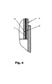
- the Fig. 3 shows the upper part of another embodiment of a suspension strut of a vehicle chassis, in which the entire strut cover 8 consists of sandwich material 9, which has alternating layers or layers of metal 10 and polyurethane 11, as the Fig. 4 in detail shows.
Landscapes
- Engineering & Computer Science (AREA)
- Mechanical Engineering (AREA)
- Vehicle Body Suspensions (AREA)
Abstract
Description
- Die Erfindung betrifft ein Fahrzeugfahrwerk, mit einem durch ein Federbein abgestützten Rad, wobei das Federbein zwischen Fahrwerk und Karosserie eingespannt und mit einer Feder- und einer Dämpfungseinrichtung zur Federung und Dämpfung der Karosseriebewegungen versehen ist, bei dem mindestens die Verbindung zwischen Karosserie und Federbein mit einer Zwischenlage versehen ist, die akustisch dämpfende Materialien aufweist.
- Federbeine mit Stahlfedern oder Luftfedern dienen heute insbesondere in Personenkraftwagen als besonders komfortable Federungselemente und sorgen für ein angenehmes Fahrgefiihl. Dies ist insbesondere bei Luftfedern der Fall, die je nach Straßenverhältnissen angepasst werden kann. Ein Luftfedersystem oder Niveauregelsystem besteht dabei aus den die Luftfeder und den Dämpfungseinrichtung umfassenden Luftfederbeinen für jedes Rad oder mindestens für jede Achse, aus der Luftversorgungsanlage mit einem Verdichter, einem Speicher, einem regenerierbaren Trockner, sowie aus weiteren schaltbaren oder festeingestellten pneumatischen Steuerelementen und weist dazu in aller Regel eine elektronische Steuerung auf.
- Luftfedern, die zwischen Fahrwerk und Karosserie eingespannt sind und die einen Luftfederbalg aufweisen, der wiederum zwischen einem üblicherweise karosserieseitigen Luftfederdeckel und einem fahrwerkseitigen Abrollkolben befestigt sind, kennt der Fachmann in einer Vielzahl von Ausführungen. Die Luftfeder steht im Betrieb unter einem inneren Überdruck. Der Luftfederbalg rollt unter Last und bei Federbewegungen unter Bildung einer Rollfalte auf der Außenkontur eines konzentrischen Bauteiles ab, üblicherweise auf dem Luftfederkolben/Abrollkolben. Eine derartige Luftfeder wird häufig in Straßen- oder Schienenfahrzeugen eingesetzt, um eine komfortable Federung zu erreichen. Dem Luftfederbalg ist eine Dämpfungseinrichtung zugeordnet, nämlich entweder ein hydraulischer Stoßdämpfer oder eine Luftdämpfung, die in der Luftfederung integriert ist, d.h. eine so genannte "Luftfeder-Dämpfereinheit".
- Dabei existieren sowohl Luftfedern, bei denen der Luftfederbalg nur einseitig eine Rollfalte bildet, nämlich in der Regel auf dem Abrollkolben, als auch Luftfedern, bei denen der Rollbalg unter Bildung einer beidseitigen (Roll-)Falte zwischen Luftfederdeckel und Abrollkolben eingespannt ist. Luftfedern mit einseitiger Rollfalte sind oft in Pkw zu finden, während die oft größeren und tragfähigeren Luftfedern mit beidseitiger Rollfalte eher in LKW und Schienenfahrzeuge eingebaut werden.
- Bei einer Luftfeder entsteht die einzige mechanische Verbindung zwischen Rad und Karosserie durch den Gummibalg/Luftfederbalg. Es besteht daher bereits eine recht gute akustische Entkopplung. Doch trotz allem Fahrkomfort und guter Geräuschdämpfung verbleibt ein Rest an Geräuschübertragung, der insbesondere bei besonders hochwertigen Fahrzeugen störend sein kann. Diese Geräusche können vom Reifen-Fahrbahn-Kontakt und von Relativbewegungen der Radfiihrungsteile stammen.
- Gerade bei Kraftfahrzeugen der gehobenen Klasse sind daher nicht nur bei den üblichen Stahlfederungen, sondern zunehmend auch bei Luftfederungen oder Luftfeder- und Dämpfereinheiten besondere Maßnahmen zur akustischen Entkopplung zwischen Fahrwerk und Karosserie wichtig.
- Bei Federbeinen mit Stahlfederung wurden bisher z. B. Scheiben aus porösem, elastischem Polyurethan-Schaumstoff zwischen Karosserie und Federbein gelegt. Bei Luftfedern wurden bisher wenig zusätzliche Maßnahmen für die Akustikentkopplung getroffen, jedoch sind auch hier Ausführungen getestet worden, bei denen eine Akustikentkopplung auf Basis von PUR-Schaumstoff vorhanden war. Nachteilig dabei ist es, dass das Federbein damit elastisch an der Karosserie angebunden ist und dadurch die Fahrdynamik beeinflusst wird.
- Für die Erfindung bestand also die Aufgabe, eine ausreichende eine akustische Entkopplung an kritischen Stellen bereitzustellen, ohne die Fahrdynamik wesentlich zu beeinflussen, beispielsweise auf den Rücksitzen einer Limousine, wo die Anschlussstellen der Federbeine an die Karosserie sich in der Nähe zum Ohr der Fond-Passagiere befinden.
- Gelöst wird diese Aufgabe durch die Merkmale des Hauptanspruchs. Weitere vorteilhafte Ausbildungen sind in den Unteransprüchen offenbart.
- Dabei weisen die akustisch dämpfende Materialien eine möglichst hohe akustisch wirksame innerer Reibung auf, also einen möglichst großen Verlustfaktor "d", und sind so angeordnet, dass eine direkte Übertragung von Körperschall zwischen Fahrwerk und Karosserie vermieden wird. Durch eine solche Anordnung und Ausbildung wird der Schall/Körperschall nicht geleitet und im Fahrzeug auch nicht mehr wahrnehmbar.
- Eine vorteilhafte Weiterbildung besteht darin, dass die Verbindung zwischen Karosserie und Federbein Zwischenlagen aus intrinsisch dämpfenden Metallen aufweist, so genannte "Hidamets (High Damping Metals)", wobei eine direkte Übertragung von Körperschall zwischen Fahrwerk und Karosserie dadurch vermieden wird, dass keine direkte Berührung, d.h. kein direkter Kontakt zwischen Federbein und Karosserie besteht. Solche Metalle mit intrinsischer Dämpfung oder "innerer Reibung" weisen eine Mikrostruktur auf, die eine Dämpfung bereitstellt bei der Übertragung von Körperschwingungen, d.h. die die Schwingungsenergie im Material in Wärme umwandelt. Eine solche, üblicherweise nur bei viscoelastischen Materialien bekannte Fähigkeit, besitzen auch bestimmte Metalle, von denen das bekannteste sicher Gusseisen ist, welches eine hohen Anteil an Lamellengraphit aufweist. Auch kennt man intrinsisch dämpfende Metalle mit definiert eingebauten Strukturdefekten. Während viscoelastische Materialien für viele Anwendungszwecke nur bedingt geeignet sind, können Metalle, wir in der erfindungsgemäßen Anwendung vorgesehen, gleichzeitig Kräfte übertragen und dämpfen, was bei einem Einsatz in einem Fahrzeugfahrwerk überaus gewünscht ist.
- Eine weitere vorteilhafte Ausbildung besteht darin, dass die Verbindung zwischen Karosserie und Federbein Zwischenlagen aus Sandwichmaterialien beinhaltet, welche abwechselnde Lagen oder Schichten von Metallen und Elastomeren aufweisen, also etwa abwechselnde Schichten von Metall und Gummi oder Kunststoff aufweisen. Auch dabei wird eine direkte Übertragung von Körperschall zwischen Fahrwerk und Karosserie dadurch vermieden, dass keine direkte Berührung, d.h. kein direkter Kontakt zwischen Federbein und Karosserie besteht. Mit solchen sehr einfach aufgebauten Sandwichmaterialien ergibt sich eine ähnliche Dämpfung wie mit Materialien mit intrinsischer Dämpfung. Natürlich können auch beide Maßnahmen, d.h. Sandwichmaterialien und oder mit Materialien mit intrinsischer Dämpfung kombiniert werden.
- Eine weitere vorteilhafte konstruktive Ausbildung besteht darin, dass die Zwischenlagen zwischen Federbein und Radhausdom angeordnet sind. Eine solche Anbindung ist einfach herzustellen und verhindert sicher die Übertragung von Körperschall. Gleiches gilt für eine weitere vorteilhafte Ausbildung, die darin besteht, dass die Zwischenlagen zwischen Mutternkopf zum Anschluss des Federbeins im Radhausdom und Radhausdom angeordnet sind.
- Eine weitere vorteilhafte und ergänzend anwendbare konstruktive Ausbildung besteht darin, dass die Zwischenlagen als Hülsen ausgebildet und zwischen Gewindebolzen zum Anschluss des Federbeins im Radhausdom und Radhausdom angeordnet sind. Diese Maßnahme kann auf besonders einfache Weise mit den übrigen Maßnahmen kombiniert werden.
- Eine weitere vorteilhafte Ausbildung besteht darin, dass mehrere Zwischenlagen in Form einer Packung, in einem so genannten "Stack" zusammengestellt sind. Dadurch erreicht man eine beliebige Anpassung der Dämpfungseigenschaft an die Stärke der Schallübertragung.
- Eine weitere vorteilhafte Ausbildung besteht darin, dass die unterschiedlichen Zwischenlagen eine auf unterschiedliche Frequenzen akustisch wirksame innere Reibung aufweisen, so dass auch eine Anpassung auf bestimmte Frequenzen erfolgen kann und besonders unangenehme Geräusch stärker bedämpft werden können.
- Anhand eines Ausführungsbeispieles soll die Erfindung näher erläutert werden. Es zeigen
- Fig. 1
- den oberen Teil eines Federbeins eines erfindungsgemäßen Fahrzeugfahrwerks ,
- Fig. 2
- zwei verschiedene Ausführungen von Zwischenlagen für das erfindungsgemäße Fahrzeugfahrwerk ,
- Fig. 3
- einer weiter Ausführung eines Federbeins eines erfindungsgemäßen Fahrzeugfahrwerks,
- Fig. 4
- eine Detailansicht der
Fig. 3 . - Die
Fig. 1 zeigt den oberen Teil eines Federbeins eines Fahrzeugfahrwerks, nämlich den Federbeindeckel 1 eines hier nicht weiter dargestellten Luftfederbeins für ein Rad, wobei das Federbein zwischen hier ebenfalls nicht näher dargestelltem Fahrwerk und dem zur Karosserie gehörigen Radhausdom 2 eingespannt ist. - Die Verbindung zwischen Karosserie und Federbein beinhaltet akustisch dämpfende Materialien, die eine akustisch wirksame innerer Reibung aufweisen und so angeordnet sind, dass eine direkte Übertragung von Körperschall zwischen Fahrwerk und Karosserie vermieden wird.
- Die
Fig. 2 zeigt dabei auf der rechten Seite eine Verbindung zwischen Karosserie und Federbein, die so gestaltet ist, dass Zwischenlagen aus intrinsisch dämpfenden Metallen 3 vorgesehen sind, und auf der linken Seite eine Verbindung zwischen Karosserie und Federbein, bei der die Zwischenlagen aus Sandwichmaterialien 4 bestehen, welche abwechselnde Lagen oder Schichten von Metallen und Polyurethan aufweisen. - Die Zwischenlagen sind in beiden Fällen zwischen Federbeindeckel 1 und Radhausdom 2 angeordnet sind.
- Eine weitere Zwischenlage ist in Form eine Hülse 5 zwischen Mutternkopf 6 zum Anschluss des Federbeins und Gewindebolzen 7 zum Anschluss des Federbeins und Radhausdom 2 angeordnet.
- Die
Fig. 3 zeigt den oberen Teil einer anderen Ausführung eines Federbeins eines Fahrzeugfahrwerks, bei dem der gesamte Federbeindeckel 8 aus Sandwichmaterial 9 besteht, welches abwechselnde Lagen oder Schichten von Metall 10 und Polyurethan 11 aufweist, wie dieFig. 4 im Detail zeigt. -
- 1
- Federbeindeckel
- 2
- Radhausdom
- 3
- Intrinsisch dämpfendes Material
- 4
- Sandwichmaterial
- 5
- Hülse
- 6
- Mutternkopf
- 7
- Gewindebolzen
- 8
- Federbeindeckel
- 9
- Sandwichmaterial
- 10
- Metall
- 11
- Polyurethan
Claims (8)
- Fahrzeugfahrwerk, mit einem durch ein Federbein abgestützten Rad, wobei das Federbein zwischen Fahrwerk und Karosserie eingespannt und mit einer Feder- und einer Dämpfungseinrichtung zur Federung und Dämpfung der Karosseriebewegungen versehen ist, bei dem mindestens die Verbindung zwischen Karosserie und Federbein akustisch dämpfende Materialien (3, 4, 9) aufweist, dadurch gekennzeichnet, dass die akustisch dämpfenden Materialien (3, 4, 9) eine akustisch wirksame innerer Reibung aufweisen und so angeordnet sind, dass eine direkte Übertragung von Körperschall zwischen Fahrwerk und Karosserie vermieden wird.
- Fahrzeugfahrwerk nach Anspruch 1, bei dem die Verbindung zwischen Karosserie und Federbein Zwischenlagen aus intrinsisch dämpfenden Metallen (3) aufweist.
- Fahrzeugfahrwerk nach Anspruch 1 oder 2, bei dem die Verbindung zwischen Karosserie und Federbein Zwischenlagen aus Sandwichmaterialien (4) beinhaltet, welche abwechselnde Lagen oder Schichten von Metallen (10) und Elastomeren (11) aufweisen.
- Fahrzeugfahrwerk Anspruch 2 oder 3, bei dem die Zwischenlagen zwischen Federbein und Radhausdom angeordnet sind.
- Fahrzeugfahrwerk nach einem der Ansprüche 2 bis 4, bei dem die Zwischenlagen zwischen Mutternkopf (6) zum Anschluss des Federbeins im Radhausdom und Radhausdom angeordnet sind.
- Fahrzeugfahrwerk nach einem der Ansprüche 2 bis 5, bei dem die Zwischenlagen als Hülsen (5) ausgebildet und zwischen Gewindebolzen (7) zum Anschluss des Federbeins im Radhausdom und Radhausdom angeordnet sind.
- Fahrzeugfahrwerk nach einem der Ansprüche 2 bis 6, bei dem mehrere Zwischenlagen in Form einer Packung zusammengestellt sind.
- Fahrzeugfahrwerk nach Anspruch 7, bei dem die unterschiedlichen Zwischenlagen eine auf unterschiedliche Frequenzen akustisch wirksame innere Reibung aufweisen.
Applications Claiming Priority (1)
| Application Number | Priority Date | Filing Date | Title |
|---|---|---|---|
| DE102010017084A DE102010017084A1 (de) | 2010-05-26 | 2010-05-26 | Akustische Entkopplung in Fahrzeugfahrwerken |
Publications (2)
| Publication Number | Publication Date |
|---|---|
| EP2390120A1 true EP2390120A1 (de) | 2011-11-30 |
| EP2390120B1 EP2390120B1 (de) | 2013-04-24 |
Family
ID=44509939
Family Applications (1)
| Application Number | Title | Priority Date | Filing Date |
|---|---|---|---|
| EP11164537.0A Not-in-force EP2390120B1 (de) | 2010-05-26 | 2011-05-03 | Akustische Entkopplung in Fahrzeugfahrwerken |
Country Status (2)
| Country | Link |
|---|---|
| EP (1) | EP2390120B1 (de) |
| DE (1) | DE102010017084A1 (de) |
Cited By (4)
| Publication number | Priority date | Publication date | Assignee | Title |
|---|---|---|---|---|
| WO2014090870A1 (de) * | 2012-12-14 | 2014-06-19 | Continental Teves Ag & Co. Ohg | Fahrzeugfahrwerk mit akustiklager |
| WO2016131629A1 (de) | 2015-02-20 | 2016-08-25 | Thyssenkrupp Steel Europe Ag | Fahrwerkkomponente, verfahren zu seiner herstellung und verwendung |
| DE102018201607A1 (de) | 2018-02-02 | 2019-08-08 | Bayerische Motoren Werke Aktiengesellschaft | Luftfederbeinverbindung mit einer Kraftfahrzeugkarosserie |
| WO2020161043A1 (de) * | 2019-02-04 | 2020-08-13 | Continental Teves Ag & Co. Ohg | Vorrichtung zur befestigung einer luftfeder mit akustischer entkopplung |
Families Citing this family (1)
| Publication number | Priority date | Publication date | Assignee | Title |
|---|---|---|---|---|
| DE102017215348B4 (de) | 2016-09-02 | 2024-06-13 | Continental Automotive Technologies GmbH | Luftfederbein mit Akustiklager |
Citations (11)
| Publication number | Priority date | Publication date | Assignee | Title |
|---|---|---|---|---|
| FR1340117A (fr) * | 1962-12-04 | 1963-10-11 | Gomma Antivibranti Applic | Dispositif pour isoler contre les vibrations les carrosseries de voitures automobiles |
| EP0318696A2 (de) * | 1987-12-04 | 1989-06-07 | Bridgestone/Firestone, Inc. | Luftfederaufhängung mit zweiseitiger Isolierung |
| JPH03244844A (ja) * | 1990-02-20 | 1991-10-31 | Tokico Ltd | エアサスペンション |
| DE4214093A1 (de) * | 1991-05-31 | 1992-12-03 | Nissan Motor | Stuetzlager fuer eine federbein-radaufhaengung |
| US5232209A (en) * | 1990-12-13 | 1993-08-03 | Caoutchouc Manufacture Et Plastiques S.A. | Macpherson strut assembly or the like |
| DE19716733A1 (de) * | 1997-04-14 | 1998-10-15 | J & S Gmbh Werkzeugbau Stanz U | Abschirmblech |
| DE19960457A1 (de) * | 1999-03-06 | 2000-09-14 | Porsche Ag | Lagerung für ein Dämpferbein oder eine Luftfeder einer Radaufhängung |
| EP1054386A2 (de) * | 1999-05-19 | 2000-11-22 | Nichias Corporation | Schwingungsdämpfende Scheibe und Methode zu deren Befestigung an einer Wärmedämmplatte |
| US20020145242A1 (en) * | 2000-11-20 | 2002-10-10 | Honda Giken Kogyo Kabushiki Kaisha | Liquid-encapsulated damper mount and hydraulic damper mounting structure in suspension of automobile |
| DE69914149T2 (de) * | 1998-10-07 | 2004-09-02 | Fuji Jukogyo K.K. | Fahrzeugaufhängungssystem |
| JP2005138657A (ja) * | 2003-11-05 | 2005-06-02 | Sekisui Chem Co Ltd | 自動車の防音構造 |
-
2010
- 2010-05-26 DE DE102010017084A patent/DE102010017084A1/de not_active Withdrawn
-
2011
- 2011-05-03 EP EP11164537.0A patent/EP2390120B1/de not_active Not-in-force
Patent Citations (11)
| Publication number | Priority date | Publication date | Assignee | Title |
|---|---|---|---|---|
| FR1340117A (fr) * | 1962-12-04 | 1963-10-11 | Gomma Antivibranti Applic | Dispositif pour isoler contre les vibrations les carrosseries de voitures automobiles |
| EP0318696A2 (de) * | 1987-12-04 | 1989-06-07 | Bridgestone/Firestone, Inc. | Luftfederaufhängung mit zweiseitiger Isolierung |
| JPH03244844A (ja) * | 1990-02-20 | 1991-10-31 | Tokico Ltd | エアサスペンション |
| US5232209A (en) * | 1990-12-13 | 1993-08-03 | Caoutchouc Manufacture Et Plastiques S.A. | Macpherson strut assembly or the like |
| DE4214093A1 (de) * | 1991-05-31 | 1992-12-03 | Nissan Motor | Stuetzlager fuer eine federbein-radaufhaengung |
| DE19716733A1 (de) * | 1997-04-14 | 1998-10-15 | J & S Gmbh Werkzeugbau Stanz U | Abschirmblech |
| DE69914149T2 (de) * | 1998-10-07 | 2004-09-02 | Fuji Jukogyo K.K. | Fahrzeugaufhängungssystem |
| DE19960457A1 (de) * | 1999-03-06 | 2000-09-14 | Porsche Ag | Lagerung für ein Dämpferbein oder eine Luftfeder einer Radaufhängung |
| EP1054386A2 (de) * | 1999-05-19 | 2000-11-22 | Nichias Corporation | Schwingungsdämpfende Scheibe und Methode zu deren Befestigung an einer Wärmedämmplatte |
| US20020145242A1 (en) * | 2000-11-20 | 2002-10-10 | Honda Giken Kogyo Kabushiki Kaisha | Liquid-encapsulated damper mount and hydraulic damper mounting structure in suspension of automobile |
| JP2005138657A (ja) * | 2003-11-05 | 2005-06-02 | Sekisui Chem Co Ltd | 自動車の防音構造 |
Cited By (8)
| Publication number | Priority date | Publication date | Assignee | Title |
|---|---|---|---|---|
| WO2014090870A1 (de) * | 2012-12-14 | 2014-06-19 | Continental Teves Ag & Co. Ohg | Fahrzeugfahrwerk mit akustiklager |
| WO2016131629A1 (de) | 2015-02-20 | 2016-08-25 | Thyssenkrupp Steel Europe Ag | Fahrwerkkomponente, verfahren zu seiner herstellung und verwendung |
| DE102015203128A1 (de) | 2015-02-20 | 2016-08-25 | Thyssenkrupp Ag | Fahrwerkkomponente, Verfahren zu seiner Herstellung und Verwendung |
| DE102018201607A1 (de) | 2018-02-02 | 2019-08-08 | Bayerische Motoren Werke Aktiengesellschaft | Luftfederbeinverbindung mit einer Kraftfahrzeugkarosserie |
| WO2020161043A1 (de) * | 2019-02-04 | 2020-08-13 | Continental Teves Ag & Co. Ohg | Vorrichtung zur befestigung einer luftfeder mit akustischer entkopplung |
| CN113272163A (zh) * | 2019-02-04 | 2021-08-17 | 大陆-特韦斯贸易合伙股份公司及两合公司 | 用于固定具有声学解耦功能的空气弹簧的装置 |
| US11827066B2 (en) | 2019-02-04 | 2023-11-28 | Continental Teves Ag & Co. Ohg | Device for securing a pneumatic spring with an acoustic decoupling function |
| CN113272163B (zh) * | 2019-02-04 | 2024-03-22 | 大陆汽车科技有限公司 | 用于固定具有声学解耦功能的空气弹簧的装置 |
Also Published As
| Publication number | Publication date |
|---|---|
| EP2390120B1 (de) | 2013-04-24 |
| DE102010017084A1 (de) | 2011-12-01 |
Similar Documents
| Publication | Publication Date | Title |
|---|---|---|
| EP2605923B1 (de) | Luftfederbein mit elastischer kolbenlagerung | |
| EP2780607B1 (de) | Luftfeder | |
| DE102011112130A1 (de) | Luftfedervorrichtung für ein Kraftfahrzeug | |
| EP2390120B1 (de) | Akustische Entkopplung in Fahrzeugfahrwerken | |
| DE4214093C2 (de) | Stützlager für eine Federbein-Radaufhängung | |
| DE102013211666A1 (de) | Luftfeder | |
| EP2847487B1 (de) | Luftfeder und verfahren zum umschlagen eines luftfederbalges einer luftfeder | |
| DE10323528A1 (de) | Elastomerfeder, insbesondere für Schienenfahrzeuge | |
| DE102015200181A1 (de) | Federunterlage für eine Fahrzeugradaufhängung und Fahrzeugradaufhängung | |
| DE102004025765A1 (de) | Federvorrichtung, insbesondere für den Schienenfahrzeugbereich | |
| EP2003363A2 (de) | Luftfedereinrichtung | |
| DE102011055399A1 (de) | Federsystem für ein Schienenfahrzeug | |
| DE102018201435A1 (de) | Achsaufhängung | |
| EP2180204B1 (de) | Zusatzfeder mit Gleitfläche | |
| DE102014109887B4 (de) | Fahrzeugkarosserie-Verstärkungsstruktur | |
| DE102011116899A1 (de) | Federbein | |
| DE102015007127A1 (de) | Baukastensystem für eine Mehrzahl von Bauvarianten einer Luftfeder für Fahrzeuge | |
| DE102019131716B4 (de) | Hilfsrahmen für ein Kraftfahrzeug | |
| DE102012018883A1 (de) | Zusatzfeder | |
| EP3672858B1 (de) | Luftfedersystem für ein schienenfahrzeug | |
| DE202016103190U1 (de) | Radaufhängungseinheit für ein Kraftfahrzeug | |
| DE102005046505A1 (de) | Federbeinabstützung eines Fahrzeugrads | |
| DE102016210072A1 (de) | Radaufhängungseinheit für ein Kraftfahrzeug | |
| DE102012220754A1 (de) | Luftfeder | |
| DE19956039B4 (de) | Radfederung mit Zentralfeder für ein Fahrzeug |
Legal Events
| Date | Code | Title | Description |
|---|---|---|---|
| 17P | Request for examination filed |
Effective date: 20110503 |
|
| AK | Designated contracting states |
Kind code of ref document: A1 Designated state(s): AL AT BE BG CH CY CZ DE DK EE ES FI FR GB GR HR HU IE IS IT LI LT LU LV MC MK MT NL NO PL PT RO RS SE SI SK SM TR |
|
| AX | Request for extension of the european patent |
Extension state: BA ME |
|
| PUAI | Public reference made under article 153(3) epc to a published international application that has entered the european phase |
Free format text: ORIGINAL CODE: 0009012 |
|
| 17Q | First examination report despatched |
Effective date: 20111118 |
|
| RIC1 | Information provided on ipc code assigned before grant |
Ipc: B32B 5/04 20060101ALI20121119BHEP Ipc: G10K 11/168 20060101ALI20121119BHEP Ipc: B60G 15/12 20060101AFI20121119BHEP Ipc: B32B 15/06 20060101ALI20121119BHEP Ipc: G10K 11/16 20060101ALI20121119BHEP Ipc: B32B 25/04 20060101ALI20121119BHEP Ipc: B32B 15/08 20060101ALI20121119BHEP Ipc: B32B 27/40 20060101ALI20121119BHEP Ipc: B32B 27/06 20060101ALI20121119BHEP Ipc: B32B 1/00 20060101ALI20121119BHEP Ipc: B60R 13/08 20060101ALI20121119BHEP |
|
| GRAP | Despatch of communication of intention to grant a patent |
Free format text: ORIGINAL CODE: EPIDOSNIGR1 |
|
| GRAS | Grant fee paid |
Free format text: ORIGINAL CODE: EPIDOSNIGR3 |
|
| GRAA | (expected) grant |
Free format text: ORIGINAL CODE: 0009210 |
|
| AK | Designated contracting states |
Kind code of ref document: B1 Designated state(s): AL AT BE BG CH CY CZ DE DK EE ES FI FR GB GR HR HU IE IS IT LI LT LU LV MC MK MT NL NO PL PT RO RS SE SI SK SM TR |
|
| REG | Reference to a national code |
Ref country code: GB Ref legal event code: FG4D Free format text: NOT ENGLISH |
|
| REG | Reference to a national code |
Ref country code: CH Ref legal event code: EP |
|
| REG | Reference to a national code |
Ref country code: AT Ref legal event code: REF Ref document number: 608379 Country of ref document: AT Kind code of ref document: T Effective date: 20130515 |
|
| REG | Reference to a national code |
Ref country code: IE Ref legal event code: FG4D Free format text: LANGUAGE OF EP DOCUMENT: GERMAN |
|
| REG | Reference to a national code |
Ref country code: DE Ref legal event code: R096 Ref document number: 502011000645 Country of ref document: DE Effective date: 20130620 |
|
| PGFP | Annual fee paid to national office [announced via postgrant information from national office to epo] |
Ref country code: FR Payment date: 20130605 Year of fee payment: 3 |
|
| REG | Reference to a national code |
Ref country code: LT Ref legal event code: MG4D |
|
| REG | Reference to a national code |
Ref country code: NL Ref legal event code: VDEP Effective date: 20130424 |
|
| PG25 | Lapsed in a contracting state [announced via postgrant information from national office to epo] |
Ref country code: LT Free format text: LAPSE BECAUSE OF FAILURE TO SUBMIT A TRANSLATION OF THE DESCRIPTION OR TO PAY THE FEE WITHIN THE PRESCRIBED TIME-LIMIT Effective date: 20130424 Ref country code: NO Free format text: LAPSE BECAUSE OF FAILURE TO SUBMIT A TRANSLATION OF THE DESCRIPTION OR TO PAY THE FEE WITHIN THE PRESCRIBED TIME-LIMIT Effective date: 20130724 Ref country code: PT Free format text: LAPSE BECAUSE OF FAILURE TO SUBMIT A TRANSLATION OF THE DESCRIPTION OR TO PAY THE FEE WITHIN THE PRESCRIBED TIME-LIMIT Effective date: 20130826 Ref country code: SE Free format text: LAPSE BECAUSE OF FAILURE TO SUBMIT A TRANSLATION OF THE DESCRIPTION OR TO PAY THE FEE WITHIN THE PRESCRIBED TIME-LIMIT Effective date: 20130424 Ref country code: ES Free format text: LAPSE BECAUSE OF FAILURE TO SUBMIT A TRANSLATION OF THE DESCRIPTION OR TO PAY THE FEE WITHIN THE PRESCRIBED TIME-LIMIT Effective date: 20130804 Ref country code: SI Free format text: LAPSE BECAUSE OF FAILURE TO SUBMIT A TRANSLATION OF THE DESCRIPTION OR TO PAY THE FEE WITHIN THE PRESCRIBED TIME-LIMIT Effective date: 20130424 Ref country code: FI Free format text: LAPSE BECAUSE OF FAILURE TO SUBMIT A TRANSLATION OF THE DESCRIPTION OR TO PAY THE FEE WITHIN THE PRESCRIBED TIME-LIMIT Effective date: 20130424 Ref country code: IS Free format text: LAPSE BECAUSE OF FAILURE TO SUBMIT A TRANSLATION OF THE DESCRIPTION OR TO PAY THE FEE WITHIN THE PRESCRIBED TIME-LIMIT Effective date: 20130824 Ref country code: GR Free format text: LAPSE BECAUSE OF FAILURE TO SUBMIT A TRANSLATION OF THE DESCRIPTION OR TO PAY THE FEE WITHIN THE PRESCRIBED TIME-LIMIT Effective date: 20130725 |
|
| PG25 | Lapsed in a contracting state [announced via postgrant information from national office to epo] |
Ref country code: BG Free format text: LAPSE BECAUSE OF FAILURE TO SUBMIT A TRANSLATION OF THE DESCRIPTION OR TO PAY THE FEE WITHIN THE PRESCRIBED TIME-LIMIT Effective date: 20130724 Ref country code: LV Free format text: LAPSE BECAUSE OF FAILURE TO SUBMIT A TRANSLATION OF THE DESCRIPTION OR TO PAY THE FEE WITHIN THE PRESCRIBED TIME-LIMIT Effective date: 20130424 Ref country code: CY Free format text: LAPSE BECAUSE OF FAILURE TO SUBMIT A TRANSLATION OF THE DESCRIPTION OR TO PAY THE FEE WITHIN THE PRESCRIBED TIME-LIMIT Effective date: 20130424 Ref country code: RS Free format text: LAPSE BECAUSE OF FAILURE TO SUBMIT A TRANSLATION OF THE DESCRIPTION OR TO PAY THE FEE WITHIN THE PRESCRIBED TIME-LIMIT Effective date: 20130424 Ref country code: PL Free format text: LAPSE BECAUSE OF FAILURE TO SUBMIT A TRANSLATION OF THE DESCRIPTION OR TO PAY THE FEE WITHIN THE PRESCRIBED TIME-LIMIT Effective date: 20130424 Ref country code: HR Free format text: LAPSE BECAUSE OF FAILURE TO SUBMIT A TRANSLATION OF THE DESCRIPTION OR TO PAY THE FEE WITHIN THE PRESCRIBED TIME-LIMIT Effective date: 20130424 |
|
| BERE | Be: lapsed |
Owner name: CONTINENTAL TEVES A.G. & CO. OHG Effective date: 20130531 |
|
| PG25 | Lapsed in a contracting state [announced via postgrant information from national office to epo] |
Ref country code: EE Free format text: LAPSE BECAUSE OF FAILURE TO SUBMIT A TRANSLATION OF THE DESCRIPTION OR TO PAY THE FEE WITHIN THE PRESCRIBED TIME-LIMIT Effective date: 20130424 Ref country code: DK Free format text: LAPSE BECAUSE OF FAILURE TO SUBMIT A TRANSLATION OF THE DESCRIPTION OR TO PAY THE FEE WITHIN THE PRESCRIBED TIME-LIMIT Effective date: 20130424 Ref country code: SK Free format text: LAPSE BECAUSE OF FAILURE TO SUBMIT A TRANSLATION OF THE DESCRIPTION OR TO PAY THE FEE WITHIN THE PRESCRIBED TIME-LIMIT Effective date: 20130424 Ref country code: CZ Free format text: LAPSE BECAUSE OF FAILURE TO SUBMIT A TRANSLATION OF THE DESCRIPTION OR TO PAY THE FEE WITHIN THE PRESCRIBED TIME-LIMIT Effective date: 20130424 Ref country code: MC Free format text: LAPSE BECAUSE OF FAILURE TO SUBMIT A TRANSLATION OF THE DESCRIPTION OR TO PAY THE FEE WITHIN THE PRESCRIBED TIME-LIMIT Effective date: 20130424 |
|
| REG | Reference to a national code |
Ref country code: IE Ref legal event code: MM4A |
|
| PG25 | Lapsed in a contracting state [announced via postgrant information from national office to epo] |
Ref country code: RO Free format text: LAPSE BECAUSE OF FAILURE TO SUBMIT A TRANSLATION OF THE DESCRIPTION OR TO PAY THE FEE WITHIN THE PRESCRIBED TIME-LIMIT Effective date: 20130424 Ref country code: IT Free format text: LAPSE BECAUSE OF FAILURE TO SUBMIT A TRANSLATION OF THE DESCRIPTION OR TO PAY THE FEE WITHIN THE PRESCRIBED TIME-LIMIT Effective date: 20130424 Ref country code: NL Free format text: LAPSE BECAUSE OF FAILURE TO SUBMIT A TRANSLATION OF THE DESCRIPTION OR TO PAY THE FEE WITHIN THE PRESCRIBED TIME-LIMIT Effective date: 20130424 Ref country code: BE Free format text: LAPSE BECAUSE OF NON-PAYMENT OF DUE FEES Effective date: 20130531 |
|
| PLBE | No opposition filed within time limit |
Free format text: ORIGINAL CODE: 0009261 |
|
| STAA | Information on the status of an ep patent application or granted ep patent |
Free format text: STATUS: NO OPPOSITION FILED WITHIN TIME LIMIT |
|
| 26N | No opposition filed |
Effective date: 20140127 |
|
| PG25 | Lapsed in a contracting state [announced via postgrant information from national office to epo] |
Ref country code: IE Free format text: LAPSE BECAUSE OF NON-PAYMENT OF DUE FEES Effective date: 20130503 |
|
| REG | Reference to a national code |
Ref country code: DE Ref legal event code: R097 Ref document number: 502011000645 Country of ref document: DE Effective date: 20140127 |
|
| REG | Reference to a national code |
Ref country code: CH Ref legal event code: PL |
|
| PG25 | Lapsed in a contracting state [announced via postgrant information from national office to epo] |
Ref country code: CH Free format text: LAPSE BECAUSE OF NON-PAYMENT OF DUE FEES Effective date: 20140531 Ref country code: LI Free format text: LAPSE BECAUSE OF NON-PAYMENT OF DUE FEES Effective date: 20140531 |
|
| PG25 | Lapsed in a contracting state [announced via postgrant information from national office to epo] |
Ref country code: MT Free format text: LAPSE BECAUSE OF FAILURE TO SUBMIT A TRANSLATION OF THE DESCRIPTION OR TO PAY THE FEE WITHIN THE PRESCRIBED TIME-LIMIT Effective date: 20130424 |
|
| REG | Reference to a national code |
Ref country code: FR Ref legal event code: ST Effective date: 20150130 |
|
| PG25 | Lapsed in a contracting state [announced via postgrant information from national office to epo] |
Ref country code: SM Free format text: LAPSE BECAUSE OF FAILURE TO SUBMIT A TRANSLATION OF THE DESCRIPTION OR TO PAY THE FEE WITHIN THE PRESCRIBED TIME-LIMIT Effective date: 20130424 Ref country code: FR Free format text: LAPSE BECAUSE OF NON-PAYMENT OF DUE FEES Effective date: 20140602 |
|
| PG25 | Lapsed in a contracting state [announced via postgrant information from national office to epo] |
Ref country code: TR Free format text: LAPSE BECAUSE OF FAILURE TO SUBMIT A TRANSLATION OF THE DESCRIPTION OR TO PAY THE FEE WITHIN THE PRESCRIBED TIME-LIMIT Effective date: 20130424 |
|
| PG25 | Lapsed in a contracting state [announced via postgrant information from national office to epo] |
Ref country code: MK Free format text: LAPSE BECAUSE OF FAILURE TO SUBMIT A TRANSLATION OF THE DESCRIPTION OR TO PAY THE FEE WITHIN THE PRESCRIBED TIME-LIMIT Effective date: 20130424 Ref country code: HU Free format text: LAPSE BECAUSE OF FAILURE TO SUBMIT A TRANSLATION OF THE DESCRIPTION OR TO PAY THE FEE WITHIN THE PRESCRIBED TIME-LIMIT; INVALID AB INITIO Effective date: 20110503 Ref country code: LU Free format text: LAPSE BECAUSE OF NON-PAYMENT OF DUE FEES Effective date: 20130503 |
|
| GBPC | Gb: european patent ceased through non-payment of renewal fee |
Effective date: 20150503 |
|
| PG25 | Lapsed in a contracting state [announced via postgrant information from national office to epo] |
Ref country code: GB Free format text: LAPSE BECAUSE OF NON-PAYMENT OF DUE FEES Effective date: 20150503 |
|
| REG | Reference to a national code |
Ref country code: AT Ref legal event code: MM01 Ref document number: 608379 Country of ref document: AT Kind code of ref document: T Effective date: 20160503 |
|
| PG25 | Lapsed in a contracting state [announced via postgrant information from national office to epo] |
Ref country code: AT Free format text: LAPSE BECAUSE OF FAILURE TO SUBMIT A TRANSLATION OF THE DESCRIPTION OR TO PAY THE FEE WITHIN THE PRESCRIBED TIME-LIMIT Effective date: 20130424 |
|
| PG25 | Lapsed in a contracting state [announced via postgrant information from national office to epo] |
Ref country code: AT Free format text: LAPSE BECAUSE OF FAILURE TO SUBMIT A TRANSLATION OF THE DESCRIPTION OR TO PAY THE FEE WITHIN THE PRESCRIBED TIME-LIMIT Effective date: 20160503 |
|
| PG25 | Lapsed in a contracting state [announced via postgrant information from national office to epo] |
Ref country code: AL Free format text: LAPSE BECAUSE OF FAILURE TO SUBMIT A TRANSLATION OF THE DESCRIPTION OR TO PAY THE FEE WITHIN THE PRESCRIBED TIME-LIMIT Effective date: 20130424 |
|
| PGFP | Annual fee paid to national office [announced via postgrant information from national office to epo] |
Ref country code: DE Payment date: 20220531 Year of fee payment: 12 |
|
| REG | Reference to a national code |
Ref country code: DE Ref legal event code: R081 Ref document number: 502011000645 Country of ref document: DE Owner name: CONTINENTAL AUTOMOTIVE TECHNOLOGIES GMBH, DE Free format text: FORMER OWNER: CONTINENTAL TEVES AG & CO. OHG, 60488 FRANKFURT, DE |
|
| REG | Reference to a national code |
Ref country code: DE Ref legal event code: R119 Ref document number: 502011000645 Country of ref document: DE |
|
| PG25 | Lapsed in a contracting state [announced via postgrant information from national office to epo] |
Ref country code: DE Free format text: LAPSE BECAUSE OF NON-PAYMENT OF DUE FEES Effective date: 20231201 |