EP2389698B1 - Bipolarbatteriebaugruppe - Google Patents
Bipolarbatteriebaugruppe Download PDFInfo
- Publication number
- EP2389698B1 EP2389698B1 EP10701178.5A EP10701178A EP2389698B1 EP 2389698 B1 EP2389698 B1 EP 2389698B1 EP 10701178 A EP10701178 A EP 10701178A EP 2389698 B1 EP2389698 B1 EP 2389698B1
- Authority
- EP
- European Patent Office
- Prior art keywords
- substrate
- battery
- negative
- electrically conductive
- frame member
- Prior art date
- Legal status (The legal status is an assumption and is not a legal conclusion. Google has not performed a legal analysis and makes no representation as to the accuracy of the status listed.)
- Active
Links
- 239000000758 substrate Substances 0.000 claims description 178
- 239000004020 conductor Substances 0.000 claims description 52
- 239000000463 material Substances 0.000 claims description 49
- 229910000679 solder Inorganic materials 0.000 claims description 30
- 239000003792 electrolyte Substances 0.000 claims description 24
- 230000005404 monopole Effects 0.000 claims description 24
- 229920000122 acrylonitrile butadiene styrene Polymers 0.000 claims description 20
- 239000004676 acrylonitrile butadiene styrene Substances 0.000 claims description 19
- 239000000853 adhesive Substances 0.000 claims description 19
- 230000001070 adhesive effect Effects 0.000 claims description 19
- 238000001816 cooling Methods 0.000 claims description 18
- 239000010949 copper Substances 0.000 claims description 18
- 230000009466 transformation Effects 0.000 claims description 18
- XECAHXYUAAWDEL-UHFFFAOYSA-N acrylonitrile butadiene styrene Chemical compound C=CC=C.C=CC#N.C=CC1=CC=CC=C1 XECAHXYUAAWDEL-UHFFFAOYSA-N 0.000 claims description 17
- 238000000034 method Methods 0.000 claims description 16
- 238000002844 melting Methods 0.000 claims description 15
- 230000008018 melting Effects 0.000 claims description 15
- RYGMFSIKBFXOCR-UHFFFAOYSA-N Copper Chemical compound [Cu] RYGMFSIKBFXOCR-UHFFFAOYSA-N 0.000 claims description 11
- 229910052802 copper Inorganic materials 0.000 claims description 11
- ATJFFYVFTNAWJD-UHFFFAOYSA-N Tin Chemical compound [Sn] ATJFFYVFTNAWJD-UHFFFAOYSA-N 0.000 claims description 8
- 230000000712 assembly Effects 0.000 claims description 8
- 238000000429 assembly Methods 0.000 claims description 8
- 238000004519 manufacturing process Methods 0.000 claims description 7
- PXHVJJICTQNCMI-UHFFFAOYSA-N Nickel Chemical compound [Ni] PXHVJJICTQNCMI-UHFFFAOYSA-N 0.000 claims description 6
- 239000012790 adhesive layer Substances 0.000 claims description 6
- 229910052718 tin Inorganic materials 0.000 claims description 6
- 208000032953 Device battery issue Diseases 0.000 claims description 4
- 239000004793 Polystyrene Substances 0.000 claims description 4
- 230000015556 catabolic process Effects 0.000 claims description 4
- 238000006731 degradation reaction Methods 0.000 claims description 4
- 239000000203 mixture Substances 0.000 claims description 4
- 229920002223 polystyrene Polymers 0.000 claims description 4
- 239000004800 polyvinyl chloride Substances 0.000 claims description 4
- 229920000915 polyvinyl chloride Polymers 0.000 claims description 4
- WHXSMMKQMYFTQS-UHFFFAOYSA-N Lithium Chemical compound [Li] WHXSMMKQMYFTQS-UHFFFAOYSA-N 0.000 claims description 3
- BQCADISMDOOEFD-UHFFFAOYSA-N Silver Chemical compound [Ag] BQCADISMDOOEFD-UHFFFAOYSA-N 0.000 claims description 3
- HCHKCACWOHOZIP-UHFFFAOYSA-N Zinc Chemical compound [Zn] HCHKCACWOHOZIP-UHFFFAOYSA-N 0.000 claims description 3
- 229910052787 antimony Inorganic materials 0.000 claims description 3
- WATWJIUSRGPENY-UHFFFAOYSA-N antimony atom Chemical compound [Sb] WATWJIUSRGPENY-UHFFFAOYSA-N 0.000 claims description 3
- 229910052797 bismuth Inorganic materials 0.000 claims description 3
- JCXGWMGPZLAOME-UHFFFAOYSA-N bismuth atom Chemical compound [Bi] JCXGWMGPZLAOME-UHFFFAOYSA-N 0.000 claims description 3
- 229910052738 indium Inorganic materials 0.000 claims description 3
- APFVFJFRJDLVQX-UHFFFAOYSA-N indium atom Chemical compound [In] APFVFJFRJDLVQX-UHFFFAOYSA-N 0.000 claims description 3
- 239000011133 lead Substances 0.000 claims description 3
- 229910052744 lithium Inorganic materials 0.000 claims description 3
- 229910052759 nickel Inorganic materials 0.000 claims description 3
- 229910052709 silver Inorganic materials 0.000 claims description 3
- 239000004332 silver Substances 0.000 claims description 3
- 239000011135 tin Substances 0.000 claims description 3
- 229910052725 zinc Inorganic materials 0.000 claims description 3
- 239000011701 zinc Substances 0.000 claims description 3
- 239000000155 melt Substances 0.000 claims description 2
- 238000010276 construction Methods 0.000 description 54
- 239000010410 layer Substances 0.000 description 39
- 239000011888 foil Substances 0.000 description 28
- 239000002253 acid Substances 0.000 description 26
- QAOWNCQODCNURD-UHFFFAOYSA-N Sulfuric acid Chemical compound OS(O)(=O)=O QAOWNCQODCNURD-UHFFFAOYSA-N 0.000 description 18
- 229920003023 plastic Polymers 0.000 description 15
- 239000004033 plastic Substances 0.000 description 15
- 239000011149 active material Substances 0.000 description 12
- 230000000694 effects Effects 0.000 description 11
- 239000000523 sample Substances 0.000 description 11
- 238000013459 approach Methods 0.000 description 9
- 230000015572 biosynthetic process Effects 0.000 description 9
- 239000004568 cement Substances 0.000 description 9
- 238000006073 displacement reaction Methods 0.000 description 9
- UIIMBOGNXHQVGW-UHFFFAOYSA-M Sodium bicarbonate Chemical compound [Na+].OC([O-])=O UIIMBOGNXHQVGW-UHFFFAOYSA-M 0.000 description 8
- 230000002829 reductive effect Effects 0.000 description 8
- 239000012811 non-conductive material Substances 0.000 description 7
- 239000007774 positive electrode material Substances 0.000 description 7
- 229920001187 thermosetting polymer Polymers 0.000 description 7
- 239000004593 Epoxy Substances 0.000 description 6
- KFZMGEQAYNKOFK-UHFFFAOYSA-N Isopropanol Chemical compound CC(C)O KFZMGEQAYNKOFK-UHFFFAOYSA-N 0.000 description 6
- 230000006835 compression Effects 0.000 description 6
- 238000007906 compression Methods 0.000 description 6
- 230000005611 electricity Effects 0.000 description 6
- 230000005496 eutectics Effects 0.000 description 6
- 239000011521 glass Substances 0.000 description 6
- 239000007773 negative electrode material Substances 0.000 description 6
- 238000007639 printing Methods 0.000 description 6
- 239000005060 rubber Substances 0.000 description 6
- 239000002826 coolant Substances 0.000 description 5
- LQBJWKCYZGMFEV-UHFFFAOYSA-N lead tin Chemical compound [Sn].[Pb] LQBJWKCYZGMFEV-UHFFFAOYSA-N 0.000 description 5
- 229920001169 thermoplastic Polymers 0.000 description 5
- 239000004416 thermosoftening plastic Substances 0.000 description 5
- 230000002745 absorbent Effects 0.000 description 4
- 239000002250 absorbent Substances 0.000 description 4
- 230000008901 benefit Effects 0.000 description 4
- 239000012809 cooling fluid Substances 0.000 description 4
- 239000000112 cooling gas Substances 0.000 description 4
- 238000013461 design Methods 0.000 description 4
- 238000010438 heat treatment Methods 0.000 description 4
- 238000005259 measurement Methods 0.000 description 4
- 229910052751 metal Inorganic materials 0.000 description 4
- 239000002184 metal Substances 0.000 description 4
- 230000001681 protective effect Effects 0.000 description 4
- 229910000030 sodium bicarbonate Inorganic materials 0.000 description 4
- 235000017557 sodium bicarbonate Nutrition 0.000 description 4
- 238000012360 testing method Methods 0.000 description 4
- 239000004698 Polyethylene Substances 0.000 description 3
- 230000005540 biological transmission Effects 0.000 description 3
- 239000004035 construction material Substances 0.000 description 3
- 230000007797 corrosion Effects 0.000 description 3
- 238000005260 corrosion Methods 0.000 description 3
- 230000007547 defect Effects 0.000 description 3
- YADSGOSSYOOKMP-UHFFFAOYSA-N dioxolead Chemical compound O=[Pb]=O YADSGOSSYOOKMP-UHFFFAOYSA-N 0.000 description 3
- 238000007599 discharging Methods 0.000 description 3
- 239000012530 fluid Substances 0.000 description 3
- 229910000464 lead oxide Inorganic materials 0.000 description 3
- YEXPOXQUZXUXJW-UHFFFAOYSA-N oxolead Chemical compound [Pb]=O YEXPOXQUZXUXJW-UHFFFAOYSA-N 0.000 description 3
- 239000008188 pellet Substances 0.000 description 3
- -1 polyethylene Polymers 0.000 description 3
- 230000008569 process Effects 0.000 description 3
- 235000001674 Agaricus brunnescens Nutrition 0.000 description 2
- 239000004831 Hot glue Substances 0.000 description 2
- RTAQQCXQSZGOHL-UHFFFAOYSA-N Titanium Chemical group [Ti] RTAQQCXQSZGOHL-UHFFFAOYSA-N 0.000 description 2
- 239000011324 bead Substances 0.000 description 2
- 238000005422 blasting Methods 0.000 description 2
- 229910052799 carbon Inorganic materials 0.000 description 2
- 239000002131 composite material Substances 0.000 description 2
- 230000003247 decreasing effect Effects 0.000 description 2
- 238000005516 engineering process Methods 0.000 description 2
- 239000007789 gas Substances 0.000 description 2
- 231100001261 hazardous Toxicity 0.000 description 2
- 230000006872 improvement Effects 0.000 description 2
- 238000003475 lamination Methods 0.000 description 2
- 230000000670 limiting effect Effects 0.000 description 2
- 239000007788 liquid Substances 0.000 description 2
- 230000007246 mechanism Effects 0.000 description 2
- 239000007769 metal material Substances 0.000 description 2
- 238000012986 modification Methods 0.000 description 2
- 230000004048 modification Effects 0.000 description 2
- 238000005192 partition Methods 0.000 description 2
- 229920000573 polyethylene Polymers 0.000 description 2
- 239000000126 substance Substances 0.000 description 2
- 239000012815 thermoplastic material Substances 0.000 description 2
- 229910052721 tungsten Inorganic materials 0.000 description 2
- 229910017944 Ag—Cu Inorganic materials 0.000 description 1
- OKTJSMMVPCPJKN-UHFFFAOYSA-N Carbon Chemical compound [C] OKTJSMMVPCPJKN-UHFFFAOYSA-N 0.000 description 1
- 229910000881 Cu alloy Inorganic materials 0.000 description 1
- 229910000978 Pb alloy Inorganic materials 0.000 description 1
- 239000004952 Polyamide Substances 0.000 description 1
- 239000004743 Polypropylene Substances 0.000 description 1
- 229920006397 acrylic thermoplastic Polymers 0.000 description 1
- 229910045601 alloy Inorganic materials 0.000 description 1
- 239000000956 alloy Substances 0.000 description 1
- 239000006256 anode slurry Substances 0.000 description 1
- 230000004888 barrier function Effects 0.000 description 1
- 238000005452 bending Methods 0.000 description 1
- 230000009286 beneficial effect Effects 0.000 description 1
- 229920001222 biopolymer Polymers 0.000 description 1
- JWVAUCBYEDDGAD-UHFFFAOYSA-N bismuth tin Chemical compound [Sn].[Bi] JWVAUCBYEDDGAD-UHFFFAOYSA-N 0.000 description 1
- 238000006243 chemical reaction Methods 0.000 description 1
- 235000019219 chocolate Nutrition 0.000 description 1
- 239000011248 coating agent Substances 0.000 description 1
- 238000000576 coating method Methods 0.000 description 1
- 238000004891 communication Methods 0.000 description 1
- 230000001276 controlling effect Effects 0.000 description 1
- 238000005520 cutting process Methods 0.000 description 1
- 238000005137 deposition process Methods 0.000 description 1
- 238000011161 development Methods 0.000 description 1
- 238000001035 drying Methods 0.000 description 1
- 238000003487 electrochemical reaction Methods 0.000 description 1
- 239000000374 eutectic mixture Substances 0.000 description 1
- 239000000835 fiber Substances 0.000 description 1
- 239000003574 free electron Substances 0.000 description 1
- 239000003365 glass fiber Substances 0.000 description 1
- 230000009477 glass transition Effects 0.000 description 1
- 239000003292 glue Substances 0.000 description 1
- 229910021389 graphene Inorganic materials 0.000 description 1
- 229910001385 heavy metal Inorganic materials 0.000 description 1
- 229920001903 high density polyethylene Polymers 0.000 description 1
- 239000004700 high-density polyethylene Substances 0.000 description 1
- 238000007689 inspection Methods 0.000 description 1
- 230000002452 interceptive effect Effects 0.000 description 1
- 229920001684 low density polyethylene Polymers 0.000 description 1
- 239000004702 low-density polyethylene Substances 0.000 description 1
- 230000005012 migration Effects 0.000 description 1
- 238000013508 migration Methods 0.000 description 1
- 230000003278 mimic effect Effects 0.000 description 1
- 238000000465 moulding Methods 0.000 description 1
- 239000002985 plastic film Substances 0.000 description 1
- 229920000747 poly(lactic acid) Polymers 0.000 description 1
- 229920003229 poly(methyl methacrylate) Polymers 0.000 description 1
- 229920002647 polyamide Polymers 0.000 description 1
- 239000004417 polycarbonate Substances 0.000 description 1
- 229920000515 polycarbonate Polymers 0.000 description 1
- 229920000728 polyester Polymers 0.000 description 1
- 239000004626 polylactic acid Substances 0.000 description 1
- 229920001155 polypropylene Polymers 0.000 description 1
- 229920001296 polysiloxane Polymers 0.000 description 1
- 238000003825 pressing Methods 0.000 description 1
- 230000002265 prevention Effects 0.000 description 1
- 230000001737 promoting effect Effects 0.000 description 1
- 230000009467 reduction Effects 0.000 description 1
- 230000001105 regulatory effect Effects 0.000 description 1
- 238000000926 separation method Methods 0.000 description 1
- 238000007493 shaping process Methods 0.000 description 1
- 239000002356 single layer Substances 0.000 description 1
- 239000002002 slurry Substances 0.000 description 1
- 239000007787 solid Substances 0.000 description 1
- ISXSCDLOGDJUNJ-UHFFFAOYSA-N tert-butyl prop-2-enoate Chemical compound CC(C)(C)OC(=O)C=C ISXSCDLOGDJUNJ-UHFFFAOYSA-N 0.000 description 1
- XOLBLPGZBRYERU-UHFFFAOYSA-N tin dioxide Chemical compound O=[Sn]=O XOLBLPGZBRYERU-UHFFFAOYSA-N 0.000 description 1
- 229910001887 tin oxide Inorganic materials 0.000 description 1
- 238000012546 transfer Methods 0.000 description 1
- 239000013585 weight reducing agent Substances 0.000 description 1
Images


Classifications
-
- H—ELECTRICITY
- H01—ELECTRIC ELEMENTS
- H01M—PROCESSES OR MEANS, e.g. BATTERIES, FOR THE DIRECT CONVERSION OF CHEMICAL ENERGY INTO ELECTRICAL ENERGY
- H01M10/00—Secondary cells; Manufacture thereof
- H01M10/06—Lead-acid accumulators
- H01M10/18—Lead-acid accumulators with bipolar electrodes
-
- H—ELECTRICITY
- H01—ELECTRIC ELEMENTS
- H01M—PROCESSES OR MEANS, e.g. BATTERIES, FOR THE DIRECT CONVERSION OF CHEMICAL ENERGY INTO ELECTRICAL ENERGY
- H01M10/00—Secondary cells; Manufacture thereof
- H01M10/04—Construction or manufacture in general
- H01M10/0413—Large-sized flat cells or batteries for motive or stationary systems with plate-like electrodes
- H01M10/0418—Large-sized flat cells or batteries for motive or stationary systems with plate-like electrodes with bipolar electrodes
-
- H—ELECTRICITY
- H01—ELECTRIC ELEMENTS
- H01M—PROCESSES OR MEANS, e.g. BATTERIES, FOR THE DIRECT CONVERSION OF CHEMICAL ENERGY INTO ELECTRICAL ENERGY
- H01M10/00—Secondary cells; Manufacture thereof
- H01M10/06—Lead-acid accumulators
- H01M10/12—Construction or manufacture
- H01M10/126—Small-sized flat cells or batteries for portable equipment
- H01M10/127—Small-sized flat cells or batteries for portable equipment with bipolar electrodes
-
- H—ELECTRICITY
- H01—ELECTRIC ELEMENTS
- H01M—PROCESSES OR MEANS, e.g. BATTERIES, FOR THE DIRECT CONVERSION OF CHEMICAL ENERGY INTO ELECTRICAL ENERGY
- H01M10/00—Secondary cells; Manufacture thereof
- H01M10/06—Lead-acid accumulators
- H01M10/12—Construction or manufacture
- H01M10/14—Assembling a group of electrodes or separators
-
- H—ELECTRICITY
- H01—ELECTRIC ELEMENTS
- H01M—PROCESSES OR MEANS, e.g. BATTERIES, FOR THE DIRECT CONVERSION OF CHEMICAL ENERGY INTO ELECTRICAL ENERGY
- H01M10/00—Secondary cells; Manufacture thereof
- H01M10/60—Heating or cooling; Temperature control
- H01M10/61—Types of temperature control
- H01M10/613—Cooling or keeping cold
-
- H—ELECTRICITY
- H01—ELECTRIC ELEMENTS
- H01M—PROCESSES OR MEANS, e.g. BATTERIES, FOR THE DIRECT CONVERSION OF CHEMICAL ENERGY INTO ELECTRICAL ENERGY
- H01M10/00—Secondary cells; Manufacture thereof
- H01M10/60—Heating or cooling; Temperature control
- H01M10/65—Means for temperature control structurally associated with the cells
- H01M10/654—Means for temperature control structurally associated with the cells located inside the innermost case of the cells, e.g. mandrels, electrodes or electrolytes
-
- H—ELECTRICITY
- H01—ELECTRIC ELEMENTS
- H01M—PROCESSES OR MEANS, e.g. BATTERIES, FOR THE DIRECT CONVERSION OF CHEMICAL ENERGY INTO ELECTRICAL ENERGY
- H01M10/00—Secondary cells; Manufacture thereof
- H01M10/60—Heating or cooling; Temperature control
- H01M10/65—Means for temperature control structurally associated with the cells
- H01M10/655—Solid structures for heat exchange or heat conduction
- H01M10/6556—Solid parts with flow channel passages or pipes for heat exchange
- H01M10/6557—Solid parts with flow channel passages or pipes for heat exchange arranged between the cells
-
- H—ELECTRICITY
- H01—ELECTRIC ELEMENTS
- H01M—PROCESSES OR MEANS, e.g. BATTERIES, FOR THE DIRECT CONVERSION OF CHEMICAL ENERGY INTO ELECTRICAL ENERGY
- H01M10/00—Secondary cells; Manufacture thereof
- H01M10/60—Heating or cooling; Temperature control
- H01M10/65—Means for temperature control structurally associated with the cells
- H01M10/656—Means for temperature control structurally associated with the cells characterised by the type of heat-exchange fluid
- H01M10/6561—Gases
-
- H—ELECTRICITY
- H01—ELECTRIC ELEMENTS
- H01M—PROCESSES OR MEANS, e.g. BATTERIES, FOR THE DIRECT CONVERSION OF CHEMICAL ENERGY INTO ELECTRICAL ENERGY
- H01M10/00—Secondary cells; Manufacture thereof
- H01M10/60—Heating or cooling; Temperature control
- H01M10/65—Means for temperature control structurally associated with the cells
- H01M10/656—Means for temperature control structurally associated with the cells characterised by the type of heat-exchange fluid
- H01M10/6567—Liquids
-
- H—ELECTRICITY
- H01—ELECTRIC ELEMENTS
- H01M—PROCESSES OR MEANS, e.g. BATTERIES, FOR THE DIRECT CONVERSION OF CHEMICAL ENERGY INTO ELECTRICAL ENERGY
- H01M50/00—Constructional details or processes of manufacture of the non-active parts of electrochemical cells other than fuel cells, e.g. hybrid cells
- H01M50/40—Separators; Membranes; Diaphragms; Spacing elements inside cells
- H01M50/409—Separators, membranes or diaphragms characterised by the material
-
- H—ELECTRICITY
- H01—ELECTRIC ELEMENTS
- H01M—PROCESSES OR MEANS, e.g. BATTERIES, FOR THE DIRECT CONVERSION OF CHEMICAL ENERGY INTO ELECTRICAL ENERGY
- H01M50/00—Constructional details or processes of manufacture of the non-active parts of electrochemical cells other than fuel cells, e.g. hybrid cells
- H01M50/40—Separators; Membranes; Diaphragms; Spacing elements inside cells
- H01M50/463—Separators, membranes or diaphragms characterised by their shape
-
- H—ELECTRICITY
- H01—ELECTRIC ELEMENTS
- H01M—PROCESSES OR MEANS, e.g. BATTERIES, FOR THE DIRECT CONVERSION OF CHEMICAL ENERGY INTO ELECTRICAL ENERGY
- H01M50/00—Constructional details or processes of manufacture of the non-active parts of electrochemical cells other than fuel cells, e.g. hybrid cells
- H01M50/50—Current conducting connections for cells or batteries
- H01M50/528—Fixed electrical connections, i.e. not intended for disconnection
- H01M50/529—Intercell connections through partitions, e.g. in a battery casing
-
- H—ELECTRICITY
- H01—ELECTRIC ELEMENTS
- H01M—PROCESSES OR MEANS, e.g. BATTERIES, FOR THE DIRECT CONVERSION OF CHEMICAL ENERGY INTO ELECTRICAL ENERGY
- H01M50/00—Constructional details or processes of manufacture of the non-active parts of electrochemical cells other than fuel cells, e.g. hybrid cells
- H01M50/50—Current conducting connections for cells or batteries
- H01M50/572—Means for preventing undesired use or discharge
- H01M50/574—Devices or arrangements for the interruption of current
- H01M50/581—Devices or arrangements for the interruption of current in response to temperature
-
- H—ELECTRICITY
- H01—ELECTRIC ELEMENTS
- H01M—PROCESSES OR MEANS, e.g. BATTERIES, FOR THE DIRECT CONVERSION OF CHEMICAL ENERGY INTO ELECTRICAL ENERGY
- H01M10/00—Secondary cells; Manufacture thereof
- H01M10/60—Heating or cooling; Temperature control
- H01M10/62—Heating or cooling; Temperature control specially adapted for specific applications
- H01M10/625—Vehicles
-
- H—ELECTRICITY
- H01—ELECTRIC ELEMENTS
- H01M—PROCESSES OR MEANS, e.g. BATTERIES, FOR THE DIRECT CONVERSION OF CHEMICAL ENERGY INTO ELECTRICAL ENERGY
- H01M2200/00—Safety devices for primary or secondary batteries
-
- H—ELECTRICITY
- H01—ELECTRIC ELEMENTS
- H01M—PROCESSES OR MEANS, e.g. BATTERIES, FOR THE DIRECT CONVERSION OF CHEMICAL ENERGY INTO ELECTRICAL ENERGY
- H01M2200/00—Safety devices for primary or secondary batteries
- H01M2200/10—Temperature sensitive devices
- H01M2200/103—Fuse
-
- H—ELECTRICITY
- H01—ELECTRIC ELEMENTS
- H01M—PROCESSES OR MEANS, e.g. BATTERIES, FOR THE DIRECT CONVERSION OF CHEMICAL ENERGY INTO ELECTRICAL ENERGY
- H01M50/00—Constructional details or processes of manufacture of the non-active parts of electrochemical cells other than fuel cells, e.g. hybrid cells
- H01M50/50—Current conducting connections for cells or batteries
- H01M50/531—Electrode connections inside a battery casing
- H01M50/54—Connection of several leads or tabs of plate-like electrode stacks, e.g. electrode pole straps or bridges
- H01M50/541—Connection of several leads or tabs of plate-like electrode stacks, e.g. electrode pole straps or bridges for lead-acid accumulators
-
- Y—GENERAL TAGGING OF NEW TECHNOLOGICAL DEVELOPMENTS; GENERAL TAGGING OF CROSS-SECTIONAL TECHNOLOGIES SPANNING OVER SEVERAL SECTIONS OF THE IPC; TECHNICAL SUBJECTS COVERED BY FORMER USPC CROSS-REFERENCE ART COLLECTIONS [XRACs] AND DIGESTS
- Y02—TECHNOLOGIES OR APPLICATIONS FOR MITIGATION OR ADAPTATION AGAINST CLIMATE CHANGE
- Y02E—REDUCTION OF GREENHOUSE GAS [GHG] EMISSIONS, RELATED TO ENERGY GENERATION, TRANSMISSION OR DISTRIBUTION
- Y02E60/00—Enabling technologies; Technologies with a potential or indirect contribution to GHG emissions mitigation
- Y02E60/10—Energy storage using batteries
-
- Y—GENERAL TAGGING OF NEW TECHNOLOGICAL DEVELOPMENTS; GENERAL TAGGING OF CROSS-SECTIONAL TECHNOLOGIES SPANNING OVER SEVERAL SECTIONS OF THE IPC; TECHNICAL SUBJECTS COVERED BY FORMER USPC CROSS-REFERENCE ART COLLECTIONS [XRACs] AND DIGESTS
- Y02—TECHNOLOGIES OR APPLICATIONS FOR MITIGATION OR ADAPTATION AGAINST CLIMATE CHANGE
- Y02P—CLIMATE CHANGE MITIGATION TECHNOLOGIES IN THE PRODUCTION OR PROCESSING OF GOODS
- Y02P70/00—Climate change mitigation technologies in the production process for final industrial or consumer products
- Y02P70/50—Manufacturing or production processes characterised by the final manufactured product
-
- Y—GENERAL TAGGING OF NEW TECHNOLOGICAL DEVELOPMENTS; GENERAL TAGGING OF CROSS-SECTIONAL TECHNOLOGIES SPANNING OVER SEVERAL SECTIONS OF THE IPC; TECHNICAL SUBJECTS COVERED BY FORMER USPC CROSS-REFERENCE ART COLLECTIONS [XRACs] AND DIGESTS
- Y10—TECHNICAL SUBJECTS COVERED BY FORMER USPC
- Y10T—TECHNICAL SUBJECTS COVERED BY FORMER US CLASSIFICATION
- Y10T29/00—Metal working
- Y10T29/49—Method of mechanical manufacture
- Y10T29/49002—Electrical device making
- Y10T29/49108—Electric battery cell making
Definitions
- the inventions disclosed and illustrated herein relate generally to batteries, and more particularly to bipolar lead-acid battery devices.
- a conventional lead-acid battery is commonly a multi-cell structure where each cell includes a set of interdigitated monopolar positive and negative plates formed of lead or lead-alloy grids containing one or more layers of electrochemically active pastes or active materials. Positive and negative plates will generally share a common separator between them to help prevent short circuits.
- the paste on the positive electrode plate will generally include a material that provides lead dioxide (PbO 2 ), when charged, which can serve as the positive active material.
- the negative plate contains a negative active material such as sponge lead.
- An acid electrolyte such as sulfuric acid is interposed between the positive and negative plates.
- bipolar batteries have been developed that offer the potential for improvement over monopolar battery technology.
- bipolar battery construction comprises a collection of electrode plates that each contain a negative active material on one side and a positive active material on the other side, hence the terms "bipolar" and "biplate".
- the biplates generally are serially arranged in such a fashion that the positive side of one plate is directed toward the negative side of an opposing plate.
- the bipolar battery is made up of separate electrolytic cells that are defined by biplates of opposing polarities. The biplates are electrically conductive to provide a serial connection between cells.
- the biplates are typically regarded as capable of providing for improved current flow over that of conventional monopolar batteries.
- the enhanced current flow is believed to be the result of through-plate current transfer from one polarity of the biplate to the other. That is, in a conventional monopolar battery, the current must travel from one electrode plate to another of opposite polarity via a conductive path, which commonly is circuitous and of relatively considerable length.
- the significantly shortened intercell current path of a bipolar battery can thereby reduce the internal resistance of the battery, making it more efficient than the conventional monopolar battery in both discharging and charging modes of operation. Accordingly, ability to reduce internal resistance permits for the construction of a bipolar battery that is both smaller and lighter than its equivalent monopolar battery, making it a highly desirable alternative for use in the aircraft, military and electric vehicle industry where considerations of size, weight or both are of major importance.
- the bipolar battery is not without its own difficulties and problems.
- a first such difficulty involves thermal temperature control within the battery and the related desire to be able to control the temperature within the battery to produce optimum battery operating efficiency.
- Another related issue involves the desire to discontinue the flow of electricity, effectively shutting down the battery, when the battery is operating at undesirable temperature conditions, thereby helping to avoid a potentially hazardous condition.
- bipolar battery constructions have consistently used bulky end plates secured by cumbersome external structures to ensure no edge seal ruptures.
- Such bipolar batteries are generally not scalable as the thickness of the end-plate must increase with larger bipolar plate size to keep end-seal ruptures and subsequent leaking from occurring.
- bipolar batteries have generally been practically limited to small capacities to maintain high energy densities.
- bipolar battery design includes the ongoing desire to improve battery efficiency by one or more modifications for increasing energy production, reducing weight, reducing overall construction size, improving construction design to support internal compressive loads, reducing construction materials, or reducing assembly operations.
- U.S. Patent No. 4,275,130 discloses a bipolar lead acid battery construction that includes a biplate of conductive thermoplastic material, a separator plate adapted to carry active material, and means for containing and maintaining the active material and conductive biplate in operable assembly and electrical contact.
- the teachings do not appear to discuss any battery assemblies that address temperature considerations.
- U.S. Patent No. 4,510,219 discloses a lead-acid battery plate construction for use in monopolar or bipolar batteries.
- the plates described therein include a glass fiber sheet having a particulate tin oxide coating.
- the teachings of that patent do not appear directed at addressing battery temperature considerations.
- U.S. Patent No. 4,658,499 discloses a bipolar battery plate that includes metal pellets embedded in a perforated thermoplastic sheet.
- the disclosed thermoplastic materials are described as having a melting point below the melting point of lead, as the preferred metal pellet material.
- teachings of that patent do not appear directed at addressing battery temperature considerations
- U.S. Patent No. 5,585,209 describes a bipolar battery plate including a titanium core surface as a means to prevent corrosion. While the preferred materials are described as promoting temperature stability within the battery, the teachings of that patent do not appear directed at addressing an automatically controlled shut-off in the event that temperatures within the battery exceed a predetermined threshold.
- U.S. Patent No. 5,593,797 describes a bipolar battery electrode having an improved electrolyte-tight seal. While disclosing the use of conductive materials in the form of fibers or pellets within the electrode core member, the teachings of that patent likewise do not appear directed at addressing an automatically controlled shut-off in the event that temperatures within the battery exceed a predetermined threshold.
- U.S. Patent Publication No. 2004/0072074 discloses a bipolar battery electrode that is described as being substantially pore-free. The electrode is further described as including an uncured epoxy in combination with a titanium powder. Among other shortcomings in the teachings, the teachings of that patent likewise do not appear directed to temperature control features. Prior art bipolar batteries are further shown by US5510211 , CH248315 , or JP59121787 .
- a battery more particularly a lead-acid battery, and still more particularly bipolar lead acid battery that is constructed in a manner that provides improvements over conventional bipolar battery technology in one or more of the following areas: temperature control; high-temperature shut down; increased energy production; reduced weight, reduced overall construction size, improved construction design to support internal compressive loads; reduced construction materials or reduced assembly operations.
- the present teachings are able to meet one or any combination of the above needs by providing methods and structures for realizing an improved battery construction. Without intending to be limiting, among the various features of the present teachings that make such battery construction so attractive is that a robust battery can be realized by the employment of a unique pasting frame structure, by which paste may be applied to or employed in the substrates in a manner so that the appropriate desired electric conductivity can be achieved across the substrate, while also preserving a means suitable for battery shut-down in the event a predetermined temperature condition is met, and further by which adjoining plates can be suitably employed and maintained in spaced opposing relation to each other so that the internal structure creates an external seal such that no additional external structures or devices are required to seal the battery for leakage prevention.
- the present teachings contemplate a method of making a bipolar battery assembly comprising the steps of providing a substrate, forming openings in the substrate, filling the openings with an electrically conductive material, covering the substrate with first and second current collector sheets and first and second non-conductive pasting frame members.
- the electrically conductive material is an admixture that undergoes a phase transformation at a temperature that is below the thermal degradation temperature of the substrate so that at an operating temperature of the battery assembly that is below the phase transformation temperature, the dielectric substrate has an electrically conductive path via the material admixture between the first surface and the second surface of the substrate. Further, at a temperature that is above the phase transformation temperature, the electrically conductive material admixture undergoes a phase transformation that disables electrical conductivity via the electrically conductive path.
- the first current collector sheet may cover the substrate and may function as a negative current collector in a first cell of the battery on the first surface of the substrate.
- the second current collector sheet may function as a positive current collector in a second cell of the battery on the second surface of the substrate.
- the first current collector sheet and the second current collector sheet may be disposed so that the electrically conductive material and the substrate is sandwiched therebetween.
- the first non-conductive pasting frame member is positioned on the first current collector sheet in planar contact with an edge of the substrate thereby creating a leak-proof seal along the exterior of the battery; and the second non-conductive pasting frame member is positioned on the second current collector sheet in planar contact with an edge of the substrate.
- the substrate may include cooling channels embedded in the substrate.
- the cooling channels may run parallel to the face of the substrate. Further, the cooling channels may be arranged so that they do not intersect with the openings in the substrate.
- the cooling channels may also extend through the substrate, the pasting frame members and the separator frame so that a cooling conduit is formed that extends through the battery.
- the pasting frame members may also include one or more support members so that the effective distance between the edges of the battery component is reduced.
- One or more adhesive layers may also be included.
- An adhesive layer may be placed between the substrate and each of the positive and negative collector foils.
- An adhesive layer may also be placed between each of the positive and negative collector foils and their respective positive and negative non-conductive pasting frame members.
- the electrically conductive material may have a melting point so that when the battery experiences temperatures above that melting point, the electrically conductive material will fail to fill the plurality of openings. Any unfilled openings in the substrate may cause an open circuit within the battery component. Any unfilled openings in the substrate may cause increased resistance within the battery component. Any unfilled openings in the substrate may cause battery failure.
- the substrate itself has a heat distortion temperature that is sufficient to withstand any melting of the electrically conductive material that may occur.
- the structures whether from the above methods or not generally comprise a first separator frame; a negative pasting frame member having one or more edges and a supporting grid structure extending between the one or more negative pasting frame edges; a negative current collector foil; a substrate having a plurality of openings formed therein; a positive current collector foil; a positive pasting frame member having one or more edges and a supporting grid structure extending between the one or more positive pasting frame edges and a second separator frame.
- the first separator frame may include one or more edges.
- the negative pasting frame member may have one or more edges so that at least one edge of the negative pasting frame member is in planar contact with at least one edge of the separator frame.
- the substrate may also have one or more edges so that at least one edge of the substrate is in planar contact with at least one edge of the negative pasting frame member.
- the positive pasting frame member may have one or more edges so that at least one edge of the positive pasting frame member is in planar contact with at least one edge of the substrate.
- the second separator frame may have one or more edges so that at least one edge of the separator frame is in planar contact with at least one edge of the positive pasting frame member.
- edges of the pasting frame members may further include openings for receiving alignment pins or support members located on the edges of the separator frames. The locating of the alignment pins into the openings on the pasting frame members may further facilitate the forming of the external seal.
- bipolar battery constructions and materials disclosed herein provide a number of desired benefits which may include but are not limited to temperature control; high-temperature shut down; increased energy production; reduced weight; reduced overall construction size; improved construction design to support internal compressive loads; and/or reduced construction material and assembly costs.
- a method for making bipolar battery components that includes providing a dielectric substrate, forming openings in that substrate and filling those openings with an electrically conductive material admixture that undergoes a phase transformation (e.g., it chemically reacts or otherwise physically transforms from a generally self-supporting and/or hardened or state (e.g., a solid, relatively highly viscous body (such as a paste)), to a fluid such as a liquid and/or a gas) at a temperature that is below the thermal degradation temperature of the substrate (e.g., a temperature at which the material of the substrate undergoes a phase transformation that renders it as an unstable physical barrier between cells, or otherwise renders it unsuitable for functioning as a cell separator).
- a phase transformation e.g., it chemically reacts or otherwise physically transforms from a generally self-supporting and/or hardened or state (e.g., a solid, relatively highly viscous body (such as a paste)
- a fluid such as
- the electrically conductive material admixture thus is such that at an operating temperature of the battery assembly that is below its phase transformation temperature, the dielectric substrate has an electrically conductive path via the material admixture, between a first surface and an opposing second surface of the substrate, and at a temperature that is above the phase transformation temperature of the conductive material admixture, the electrically conductive material admixture undergoes a phase transformation that disables electrical conductivity via the electrically conductive path.
- a unique frame structure may be used by which one or more separator frames and one or more pasting frames, in combination with the substrate, will each lie in planar contact with adjacent frames and/or substrates so that the internal structure of the battery cell creates an external seal that prevents any liquid or air from escaping the battery.
- the edges of the pasting frame members may further include openings for receiving alignment pins or support members located on the edges of the separator frames. The locating of the alignment pins into the openings on the pasting frame members may further facilitate the forming of the external seal.
- any electrolyte introduced into the battery will be securely maintained without risk of battery leakage and subsequent battery failure. Further, no heavy end plates or external support structures are required to effectively seal the battery.
- the pasting frame members may further include support members (e.g., pins) located between the edges of the pasting frame members.
- support members e.g., pins
- the use of support members is just one approach to address the issue of compressive stress and resulting unwanted edge/peeling stress within the battery. These stresses may lead to undesirable battery leakage as discussed above.
- This use of the support pins within a battery, and the resulting internal approach discussed herein, may therefore be referred to as building a bipolar battery having an endo-skeleton.
- a feature of using the endo-skeleton build or construction approach (as compared to using an exo-skeleton build approach) to address the undesired effects of compressive stress within the battery, is that it does not result in a reduction of volumetric energy density. Additionally, it is a lightweight approach, using only a few lightweight pins with very little loss of active material. Further, the endo-skeleton build approach has been found to greatly reduce the chances of traditional bipolar battery failure mode caused by edge peeling. Further, if desired, one can add pins on the perimeter or edge of the frame members to align the separating frame member, thereby allowing it to glide up and down or back and forth during compression.
- the bipolar battery may be constructed using a combination of an endo-skeleton and exo-skeleton build approach.
- the bipolar battery can be constructed using internal support pins as described above.
- a frame structure may also be placed on the terminal side of the monopole.
- This exterior battery construction may be reinforced with an end cover as part of an aesthetic box. The combined features of an endo-skeleton and an exo-skeleton in such a construction work together to further reduce maximum edge stress and displacement.
- the bipolar battery may also be substantially free of any exo-skeleton structure.
- the construction of a conventional bipolar battery involves the placement of an electrically conductive substrate as an inter-cell partition between adjacent cells of the battery such that separation of the electrolyte in the respective cells is maintained by the conductive substrate.
- Positive active material e.g., in the form of a sheet such as a foil
- negative active material e.g., in the form of a sheet such as a foil
- the positive active material is exposed to the electrolyte of one cell and the negative active material is exposed to the electrolyte of the adjacent cell.
- the conductive substrate thereby forms a single structure electrically connecting two adjacent half cells, one positive and one negative.
- the substrate generally also will function as a supporting structure to enable collecting and transmitting current for active materials between adjacent cells.
- the substrate structure used between the cells and to which the active materials are applied may be any suitable structure. It may be a composite structure that includes at least one non-electrically conductive material and at least one electrically conductive material (e.g., a conductive material that is applied in the form of a paste in holes formed in a dielectric substrate) that provides a substantially continuous conductive flow path. For example, it may provide a conductive flow path that is substantially free of any voids, fissures or other holes or interfering non-conductive material between opposing sides of the substrate.
- a substrate can be sealed at least partially, if not entirely, about its perimeter to preclude contact between the electrolyte of adjacent cells.
- the substrate will be employed in combination with the positive and negative active material of a bipolar battery cell in a manner such that it performs one or any combination (e.g., all) of: (1) participating in the electrochemical reaction causing the evolution of free electrons, (2) serving as a cell partition, preventing the migration of electrolyte between adjacent cells, (3) intimately and effectively supporting the relevant active materials of a battery cell, (4) conducting electricity as efficiently as possible, or (5) cooperating with other battery components to form an electrolyte-tight seal about the biplate edges which may be on the outside surface of the battery.
- any combination e.g., all of: (1) participating in the electrochemical reaction causing the evolution of free electrons, (2) serving as a cell partition, preventing the migration of electrolyte between adjacent cells, (3) intimately and effectively supporting the relevant active materials of a battery cell, (4) conducting electricity as efficiently as possible, or (5) cooperating with other battery components to form an electrolyte-tight seal about the biplate edges which may be on the outside surface of the battery.
- the substrate can be formed from a variety of materials depending on the function of the battery chemistry.
- the substrate may be formed from materials that are sufficiently structurally robust to provide the backbone of a desired bipolar electrode plate.
- the substrate may be formed from suitable materials and/or is configured in a manner that permits the transmission of electricity from one surface of the substrate to an opposite substrate surface.
- the substrate plate can be formed from an electrically non-conductive material, e.g., a polymeric or plastic material, but having electrically conductive features constructed therein or thereon.
- the substrate may be formed from an electrically non-conductive material, e.g., a polymeric or plastic material, having a desired degree of structural rigidity. Further, the substrate may be formed of a material capable of withstanding temperatures that exceed the melting points of any conductive materials used in the battery construction. The substrate may also be composed of material having high chemical stability during contact with an electrolyte (e.g., sulfuric acid solution) so that the substrate does not degrade upon contact with an electrolyte.
- the substrate may be formed of a polymeric material including but not limited to thermoplastics, thermoset plastics, elastomeric containing materials or any combination thereof.
- polymeric materials examples include polyamide, polyester, polystyrene, polyethylene (including polyethylene terephthlate, high density polyethylene and low density polyethylene), polypropylene, polyvinyl chloride, bio-based plastics/biopolymers (e.g., polylactic acid), silicone, acrylonitrile butadiene styrene (ABS), or any combination thereof.
- the heat distortion temperature of a substrate formed from ABS is sufficient to withstand a solder reflow process although the temperature of said reflow process is substantially higher than the glass transition temperature of the plastic substrate.
- one possible approach is to employ a composite substrate, and more particularly a generally non-electrically conductive substrate (e.g., a dielectric substrate) that includes one or more openings formed therein.
- the openings may be machined (e.g., milled), formed during fabrication of the substrate (e.g., by a molding or shaping operation), or otherwise fabricated.
- the size and frequency of the openings formed in the substrate may affect the resistivity of the battery.
- the openings may be formed having a diameter of at least about 0.2 mm.
- the openings may be formed having a diameter of less than about 5 mm.
- the openings may be formed having a diameter from about 1.4 mm to about 1.8 mm.
- the openings may be formed having a density of at least about 0.02 openings per cm 2 .
- the openings may be formed having a density of less than about 4 openings per cm 2 .
- the openings may be formed having a density from about 2.0 openings per cm 2 to about 2.8 openings per cm 2 .
- solder material comprising a solder material comprising a mixture of any two or more of lead, tin, nickel, zinc, lithium, antimony, copper, bismuth, indium, or silver.
- solder materials include but are not limited to Sn-Ag-Cu (e.g., SnAg 3.0 Cu 0.5 , SnAg 3.5 Cu 0.7 , SnAg 3.5 Cu 0.9 , SnAg 3.8 Cu 0.7 , SnAg 3.8 Cu 0.7 Sb 0.25 , and/or SnAg 3.9 Cu 0.6 ), SnCu 0.7 , SnZn 9 , SnZn 8 Bi 3 , SnSb 5 , SnAg 2.5 Cu 0.8 Sb 0.5 , SnIn 8.0 Ag 3.5 Bi 0.5 , SnBi 57 Ag 1 , SnBi 58, SnIn 52 , and combinations thereof.
- the electrically conductive material may be substantially free of any lead
- the material may include a mixture of lead and tin.
- it may include a major portion tin and a minor portion of lead (e.g., about 55 to about 65 parts by weight tin and about 35 to about 45 parts by weight lead).
- the material may exhibit a melting temperature that is below about 240°C, 230°C, 220°C, 210°C or even below about 200°C (e.g., in the range of about 180 to about 190°C).
- the material may include a eutectic mixture.
- solder has a defined melting temperature that can be tailored, depending on the type of solder used, to melt at a temperature that may be unsafe for continued battery operation. Once the solder melts, the substrate opening containing the melted solder is no longer electrically conductive and an open circuit results within the electrode plate. An open circuit may operate to dramatically increase the resistance within the bipolar battery thereby stopping further electrical flow and shutting down unsafe reactions within the battery. Accordingly, the type of electrically conductive material selected fill the openings can vary depending on whether it is desired to include such an internal shut down mechanism within the battery, and if so at what temperature it is desired to effect such an internal shutdown.
- the substrate will be configured so that in the event of operating conditions that exceed a predetermined condition, the substrate will function to disable operation of the battery by disrupting electrical conductivity through the substrate.
- the electrically conductive material filling holes in a dielectric substrate will undergo a phase transformation (e.g., it will melt) so that electrical conductivity across the substrate is disrupted.
- the extent of the disruption may be to partially or even entirely render the function of conducting electricity through the substrate disabled.
- Yet another unique feature of the present teachings is the employment of frame structures that function to form an internal support structure that effectively produces an external seal about the battery, thereby allowing any electrolyte to be maintained within the cells with no edge peel or leakage.
- This internal support structure further reduces the need for any bulky end plates or external structures traditionally used to seal the battery. Without the need for these end plates or external structures, the number of cells used to create a battery is not limited by size and weight considerations, thus many more cells can be combined to create more power without requiring more weight and size to seal the batteries.
- the assembly may include one or more pasting frame members, separating frame members or both.
- a separating frame member may be positioned adjacent the positive pasting frame member.
- the separating frame member may operate to both separate the positive pasting frame member of one electrode assembly from the negative pasting frame member of an adjacent electrode assembly.
- the separating frame member may also provide a contained chamber for accommodating a desired volume of electrolyte therebetween.
- the separating frame member may be formed from a structurally rigid electrically nonconductive material capable of performing within a lead-acid battery environment at operating temperatures without presenting edge peel or leakage issues.
- the separating frame member and pasting frame members may be composed of polymeric materials including but not limited to thermoplastics, thermoset plastics, elastomeric containing materials or any combination thereof.
- the positive and negative pasting frame members may comprise a generally rigid frame with an open inner section that is provided to accommodate a volume of respective positive-side and negative side active material.
- the positive and negative pasting frame members may be formed from electrically nonconductive materials capable of performing within a lead-acid battery environment at operating temperatures without presenting leakage issues.
- the active materials placed within the confines of the pasting frame members include those positive and negative active materials used to form electrode surfaces in conventional bipolar batteries.
- the negative pasting frame member may be omitted from a terminating electrode assembly for the formation of a positive terminal, and the positive pasting frame member would be omitted from a terminating electrode assembly for the formation of a negative terminal.
- the battery constructions disclosed herein may also include attachments and/or support members in an effort to prevent stress-related peeling issues common to conventional bipolar batteries. Stress-related peeling issues have somewhat limited the construction of bipolar batteries of larger size and power as there are stresses placed on the battery end plates due to the compression after the battery is assembled.
- the battery construction may comprise a number of support members or pins that extend between the rigid base and the end plate.
- the pins may be positioned within the construction between the inside edges of the separating frame member to thereby reduce the effective distance between the edges within the construction.
- the pins may also reduce both the amount of maximum edge stress and end plate displacement. The placement of the pins may thus reduce the occurrence of unwanted peeling within the battery due to the effect of compressive stresses.
- the edges of the pasting frame members may further include openings for receiving alignment pins or support members located on the edges of the separator frames. The locating of the alignment pins into the openings on the pasting frame members may further facilitate the forming of an external seal.
- the pasting frame members may also include a supporting grid structure extending between the frame member edges wherein the grid structure includes a number of openings or holes extending through the grid structure to accommodate placement of support pins therethrough.
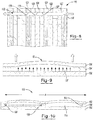
- FIG. 1 illustrates an example of a bipolar battery 10 constructed according to principles of the present teachings comprising a number of electrode plates 12 or biplates, stacked (e.g., in serial fashion) from the front to the rear (or otherwise in an arrange spanning at least partially, if not fully across the battery).
- the number and configuration of the biplates may be selected as desired to define both the length and the cross-sectional shape of the battery.
- FIG. 1 illustrates an embodiment of the bipolar battery with biplates shaped in the configuration of a square or rectangle, but other plate configurations, such as a circle, oval, hexagon and the like, can be used if desired.
- an electrode plate assembly 14 comprises a substrate 16 that is located between pasting frame members 18 and 20. Separating frame members 22 and 24 are placed in contact with respective pasting frame members 18 and 20.
- the positive and negative pasting frame members may comprise a generally rigid frame 18, 20 with an open inner section 21, 23 that is provided to accommodate a volume of respective positive-side active material 34 and negative side active material 36.
- the substrate may include a number of openings 26, holes or channels formed in the substrate and extending through the thickness of the substrate between opposite surfaces 28 and 30.
- the number and size of the openings 26 are sufficient to permit a desired flow of electricity through the substrate plate between the surfaces 28 and 30 during battery operation.
- the substrate surfaces 28 and 30 may include an electrically conductive material layer 34 and 36 respectively disposed thereon.
- the conductive material layers 34 and 36 may be provided in the form of a metallic foil.
- a preferred metallic material useful for forming the conductive material layers is one formed from lead.
- the metal foils may be attached to the substrate by a suitable adhesive capable of maintaining attachment of the foil layers to the adjacent substrate surfaces during battery operation. As noted above, during high operating temperatures sufficient to cause melting of the solder within the openings 26, the solder or other suitable conductive material diffuses in the material layers 34 and 36 leaving the openings devoid of an electrically conductive material to promote the desired open circuit condition.
- the electrode assembly 14 may also be impermeable to any unwanted leakage of electrolyte between cells.
- the conductive material used to fill the plurality of openings 26 through the substrate plate 16 completely fill the openings in such a manner so as to avoid any unwanted leakage of electrolyte therein.
- the conductive material layers 34 and 36 over the substrate plate surfaces may also operate to prevent unwanted electrolyte leakage through the plate. While it is possible that a defect in a material layer could cause leakage of electrolyte, the defect would have to be aligned with an opening through the substrate. Further, the electrically conductive material in that particular opening would have to fail to fill the opening in order for such a defect to case leakage through the electrode assembly.
- FIG. 3 illustrates an additional example substrate 40 comprising an electrically conductive interconnect layer 42 disposed internally within the substrate between the substrate layers 43 and 44, wherein the outer surfaces of the substrate layers are in contact with the electrically conductive material layers 46 and 48, respectively.
- the interconnect layer 42 may be formed from an electrically conductive material, e.g., a metallic material, and is located between two opposing substrate laminate layers that are bonded to one another.
- the substrate layers 43 and 44 can be formed from those materials described above for the substrate.
- the interconnect layer 42 permits the openings 50 running from each of the surfaces 42 and 44, and filled with a desired electrically conductive material 51, to be offset from or blind to one another so as to avoid the creation of a continuous fluid leak path through the substrate. While the conductive openings 50 running from each of the surfaces are offset from or blind to one another, they are still useful for transmitting electricity through the substrate by virtue of their connection to the common conductive interconnect layer 42.
- an electrode assembly could be formed using more than one substrate placed adjacent one another, and/or by forming a substrate construction having multiple internal layers. Such embodiments are intended to be within the scope of this invention.
- substrate plates 14 for making electrode assemblies may also be configured having one or more internal passages 52 disposed therein.
- the passages 52 can be oriented to run horizontally and/or vertically and/or diagonally within the substrate, and are ideally configured to accommodate the transmission of a cooling medium therein.
- the substrate 14 can be configured having a plurality of internal passages 52 configured and oriented to accommodate the transmission of a cooling fluid or gas therein.
- the presence of such internal cooling passages within the substrate may operate to control the temperature within the battery during operation to thereby promote optimum battery performance.
- the passages 52 can be connected by an appropriate inlet and outlet, which may be integral with or independent of the substrate.
- the inlet and outlet may direct the flow of cooling fluid or gas into and out of the multiple electrode assemblies within the battery.
- Fluid or gas control devices such as valves and the like may be used in association with the cooling passages as needed to provide a desired degree of temperature control to the bipolar battery during both operation and charging. While not shown in FIG. 3 , it is understood that such internal cooling passages 54 may be present within the particular substrate 40 presented therein.
- FIG. 4 illustrates an example laminate electrode construction 60 comprising multiple construction layers.
- a feature of such laminate electrode construction is the ability to use different material layers that are individually tailored to provide desired properties of electrical conductivity, impermeability, and corrosion resistance for use within the bipolar battery.
- the laminate electrode construction 60 is placed over each opposed substrate surface and is attached thereto, e.g., by adhesive attachment, and forms an electrically conductive material layer. While electrically conductive material layers having other types of constructions may be used, e.g., being formed from a single layer of material, the use of such a laminate electrode construction 60 provides certain desired advantages.
- the laminate electrode construction 60 may comprise an inner layer 62 formed from an electrically conductive material having a desired degree of corrosion resistance and improved conductivity.
- the inner layer 62 may be formed from a copper or copper alloy and may be provided in the form of a foil having a thickness of at least about 0.01 mm.
- the foil may have a thickness of less than about 1 mm.
- the thickness of the foil may range from about 0.05 mm to about 0.6 mm.
- Outermost layers 64 and 66 may be positioned along opposed surfaces of the inner layer and may also be formed from an electrically conductive material.
- the outermost layers 64 and 66 may be formed from lead.
- the outermost layers 64 and 66 may be provided in the form of a foil having a thickness of at least about 0.01 mm.
- the foil may have a thickness of less than about 1 mm.
- the thickness of the foil may range from about 0.05 mm to about 0.6 mm.
- the laminate electrode construction 60 may be arranged so that the outermost layers 64 and 66 are placed and held into contact with the inner layer 62 by use of intermediate layers 68 and 70, respectively.
- the intermediate layers may be formed from a an electrically conductive material having a relatively low melting point, such as the materials described previously, and the laminate construction may be formed by melting the material between the intermediate layers and pressing the layers together to ensure electrical connection therebetween.
- the intermediate layers may be formed from an electrically conductive material having a relatively low melting point, such as the materials described previously.
- a lead-tin solder material may be employed such that the layers may be pressed together at a temperature of approximately 200°C with moderate pressure to form the desired laminate electrode construction 60.
- FIG. 5 illustrates an example electrode assembly 70 prepared according to principles of the present invention.
- the electrode assembly 70 may comprise a bipolar electrode 72 that is constructed having a substrate (as shown in FIGS. 2 and 3 ) and a laminate electrode construction (as shown in FIG. 4 ) disposed along the outer surfaces of the substrate.
- the assembly 70 may further comprise one or more pasting frame members. For example it may include a positive pasting frame member 73 that is positioned adjacent one surface 74 of the electrode 72, and a negative pasting frame member 76 that is positioned adjacent an opposing surface 78 of the electrode 72.
- a separating frame member 80 may be positioned adjacent to the positive pasting frame member 73.
- the separating frame member 80 may operate to both separate the positive pasting frame member of one electrode assembly from the negative pasting frame member of an adjacent electrode assembly.
- the separating frame member 80 may also provide a contained chamber 82 for accommodating a desired volume of electrolyte therebetween.
- the separator frame 80 may also provide a displacement stop to ensure correct compression of the separator material such as an absorbent glass mat.
- the separating frame member 80 may be formed from a structurally rigid electrically nonconductive material capable of performing within a lead-acid battery environment at operating temperatures without presenting leakage issues.
- the separating frame member and pasting frame members may be composed of polymeric materials including but not limited to thermoplastics, thermoset plastics, elastomeric containing materials or any combination thereof.
- FIG. 6 illustrates an example pasting frame member 84 useful for making electrode assemblies which may include a supporting grid 86 structure positioned between the outer frame edges 88.
- the supporting grid 86 may be provided provided to both provide an enhanced degree of structural support to the pasting frame member, and to promote double sided pasting in standard pasting equipment.
- the supporting grid may provide structural support during the pasting process to prevent bowing and may also improve paste adhesion.
- protective release layers may be attached to an outer surface of the frame edges. Therefore, during post pasting operations, any active material inadvertently contacted with a frame edge can be easily removed therefrom, leaving behind a clean surface for subsequent frame attachment.
- FIG. 7 illustrates an electrode plate assembly 90 comprising an electrode 92 (including the substrate member and the outer conductive material layers disposed thereon), positive and negative pasting frame members 94 and 96 positioned onto opposite surfaces of the electrode 92, and separating frame members 98 and 100 attached to respective surfaces of the positive and negative pasting frame members 94 and 96.
- the separating frame members 98 and 100 may be attached thereto.
- the battery may then be built by stacking the electrode assemblies until the desired number of cells or voltage is achieved.
- An advantage of this stack-and-assemble method is that the pressure of the battery construction is placed uniformly across each cell, which is important to the performance of valve-regulated, lead-acid batteries.
- the battery may be filled with electrolyte through ports (not shown) present in the separating frame members.
- a valve may be attached to the separating frame member.
- the separating frame members may be configured to extend above the positive and negative pasting frame members (as shown in FIG. 7 ), which also provides additional head space for the electrolyte.
- electrode assemblies for making bipolar batteries may be configured to accommodate coolant flow therein to promote battery temperature control during normal battery operation and/or during battery charging.
- electrode assemblies of this invention may include a substrate member having one or more cooling channels disposed therein configured for facilitating the passage of a desired cooling medium therethrough to assist in controlling the internal battery temperature.
- FIG. 8 illustrates a sectional view of a bipolar battery 110 having an internal cooling system 112.
- the cooling system may comprise a cooling fluid or gas inlet and cooling fluid or gas outlet that is in communication with a cooling conduit 116 that extends through a number (e.g., all or a selected number) of the cells making up the battery.
- the cooling conduit 116 may extend through all of the cells within the battery, and may be provided in the form of aligned openings 120 that pass through the multiple substrate members 121, pasting frame members 122 and separating frame members 124.
- the cooling system may be configured to provide single or multi-pass coolant flow through the battery. Additionally, the separate members making up each battery cell can be configured to direct the flow of coolant within the battery in a manner best capable of addressing any unique battery cooling needs based on particular battery configuration and/or battery use.
- FIG. 9 depicts a conventional bipolar battery construction 130 comprising a rigid base 132, a separating frame member 134, and an end plate 136, wherein the separating frame member 134 is interposed between the rigid base and the end plate, and wherein the separating frame member includes an absorbent glass mat (AGM) 137.
- AGM absorbent glass mat
- the compression stresses caused by the AGM mat 137 can cause the end plate 136 to bow outwardly, placing maximum stress on the edge of assembly. This stress may produce unwanted internal peeling. Such edge stress has been found sufficient to peel most glues or adhesives used during bipolar battery construction. Any adhesive peeling may result in unwanted leakage of electrolyte from the battery.
- FIG. 10 illustrates a bipolar battery construction 150, prepared according to principles disclosed herein.
- the battery construction 150 comprises a rigid base 152, a separating frame member 154, and an end plate 156, wherein the separating frame member 154 is interposed between the rigid base 152 and the end plate 156, and an AGM mat 155 is disposed between the rigid base and end plate.
- a feature of the bipolar battery construction 150 is that it includes a number of support members or pins 158 that extend between the rigid base 152 and the end plate 156.
- the pins 158 are positioned within the construction between the inside edges 160 of the separating frame member 154 to thereby reduce the effective distance between the edges within the construction.
- the pins 158 may also reduce both the amount of maximum edge stress and end plate displacement. The placement of the pins 158 may thus reduce the occurrence of unwanted peeling within the battery due to the effect of compressive stresses.
- FIGS. 11 and 12 illustrate an example pasting frame member 170 comprising a supporting grid structure 172 extending between the frame member edges 174, wherein the grid structure 172 includes a number of openings or holes 176 extending through the grid structure to accommodate placement of support pins 178 (shown in FIG. 12 ) therethrough.
- the support pins 178 may have a length so that they extend between the rigid base and end plate as illustrated in FIG. 10 .
- the support pins 178 may further have a thickness so as to provide a desired level of structural support within the battery.
- the support pins 178 may be formed from an electrically nonconductive material, such as plastic or the like, that is both sufficiently rigid to provide a desired degree of support between the rigid battery members within the operating environment of a bipolar battery.
- the pins are formed from the same types of materials used to form the pasting frame members, and/or the separating frame members.
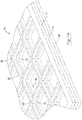
- FIGS. 13 and 14 illustrate an electrode assembly 180 comprising a positive pasting frame member 182, a separating frame member 184 disposed over the positive pasting frame member 182, and a negative pasting frame member 186 disposed over the separating frame member 184.
- the negative pasting frame member 186 may be constructed comprising a supporting grid 188 including a number of holes 190 that contain support pins 192 disposed therein.
- the support pins 192 may extend outwardly from the negative pasting frame member 186 and may be in contact with an adjacent portion of a supporting grid 194 from the positive pasting frame member 182.
- the positive pasting frame member supporting grid 194 may or may not include holes to accept placement of the support pins therein. Configured in this manner, the support pins may operate to both maintain a desired spacing between assembly members within the battery, and operate to reduce the internal edge stress existing within the battery as noted above.
- FIG. 14 illustrates a placement of the support pins 192 extending between the positive and negative pasting frame members 182 and 186.
- support pins used to construct a bipolar battery may vary depending on the particular size, configuration and/or application of the battery, and such variance is intended to be within the scope of the invention.
- support members have been described as being pins, it is to be understood that the support members can take on a variety of different shapes or configurations that are capable of performing the function noted above, and that such different shapes and configurations are understood to be within the scope of the invention.
- a substrate may be provided. It may be cut into an appropriate size and/or shape. A plurality of holes may be formed in a dielectric polymeric substrate. The substrate may be cleaned. Electrically conductive material may be applied to fill the holes. For example, it may be printed, sprayed, spread, evaporated, electroplated, or deposited by any similar deposition process. A sheet (e.g., a metal foil) is applied over each side of the substrate. It may be rolled or otherwise smoothed. The sheet may be adhered to the substrate via any suitable adhesive. Heat and/or pressure is applied for bonding the sheet to the substrate and the electrically conductive material therein.
- a sheet e.g., a metal foil
- the heat may be applied at a temperature of at least about 80°C.
- the heat may be applied at a temperature less than about 475°C.
- the pressure may be applied at greater than about 30 PSI.
- the pressure applied may be less than about 300 PSI. No pressure may be applied in some constructions.
- the resulting biplates may undergo oven heating at temperatures from about 50°C to about 200°C.
- the oven heating may be at any temperature sufficient to cure any adhesive used in the construction.
- the pasting frames may then be attached to both sides of the biplates via an adhesive.
- the biplates may be covered with a paste that may be a lead-containing paste.
- the paste may be lead oxide paste.
- the biplates may also be oven-cured after pasting.
- the biplates may then be assembled to form a battery.
- the battery assembly may include a negative monopole, a positive monopole, and a plurality of biplates therebetween.
- One or more separator frames may be placed between the monopoles and biplates.
- the separator frames may also include one or more support structures.
- One or more mat separator materials e.g., absorbent glass mats
- An adhesive e.g., a plastic cement
- the assembled battery may then be contacted with an electrolyte (e.g., sulfuric acid solution). Once filled, the fill ports may be sealed with an adhesive.
- Epoxy laminate, FR4 Micarta® board (available from Norplex Micarta, Postville, IA) is used as the substrate material.
- the substrate is 0.8 mm thick and cut to 197 x 166 mm. Seven hundred and twenty (720) 1.6 mm diameter holes 6.25 mm on center are milled into the substrate.
- the samples are lightly sanded on both faces and washed with isopropyl alcohol.
- a rubber-based, thermoset adhesive is then brushed onto both surfaces of the substrate and allowed to dry until it is tack free. Epoxy-based adhesives may also been used.
- Stencil printing is used to print a tin-lead solder paste into the holes of the substrate.
- NC650 63/37 tin-lead solder (available from FCT Assembly, Greely, CO) is used in this example.
- the solder is stencil printed first onto the positive face of the substrate. After printing, lead foil is applied to the face and rolled smooth. The foil is a 3 mil thick, 98.5% lead 1.5% tin foil. Other solders, including tin-bismuth and non-lead solders pastes may be used.
- the substrate is then flipped and solder is stencil printed onto the negative face of the substrate. After printing, lead foil, as above, is applied to the negative face and rolled smooth. Other types of foil may be used including copper, tin-plated copper, nickel-plated copper and zinc-plated copper.
- the substrate assembly is next placed into a hot-platen press. Platen temperature (top and bottom) are set for the eutectic of the solder, in this case 183°C. Pressure is applied greater than 100 PSI. The sample is pressed for 40 seconds. During this operation the solder reflows and makes electrical contact and the adhesive partially cures. The samples are then placed in an oven for 1 hour at 125°C to complete curing of the rubber-based adhesive.
- Pasting frames are then attached to the substrate assembly.
- the positive and negative pasting frames are machined from ABS plastic 1/16" thick.
- the pasting frames are attached to the substrate using a rubber-based, thermoset adhesive.
- the electrodes are placed in a jig with light pressure (1 psi) and cured overnight. After curing, the samples are cleaned using grit blasting (80 grit glass beads) until the lead foil is a uniform matte gray. The samples are then cleaned with compressed air.
- a protective film (3-mil PE tape) is applied to the positive and negative face of the pasting frames.
- the resistance of the electrode is measured using 4-point Kelvin probe over 16 points across the substrate using an Extech 380460 digital milliohm meter. All 16 resistance measurements were less than 0.1 m ⁇ , the limit of the milli-ohm meter. The samples were then dropped from a height of 8 feet. No de-lamination or damage was observed. Further, there were no changes to the resistance measurements.
- ABS Acrylonitrile-butadiene-styrene
- the substrate is 1.6 mm thick and cut to 197 mm x 186 mm. Seven hundred and twenty (720) 1.6 mm diameter holes are milled into the substrate. The samples are lightly sanded on both faces and washed with isopropyl alcohol. A rubber-based, thermoset adhesive is then brushed onto both surfaces of the substrate and allowed to dry until it is tack free.
- Stencil printing is used to print a tin-lead solder paste into the holes of the substrate.
- NC650 63/37 tin-lead solder (available from FCT Assembly, Greely, CO) is used in this example.
- the solder is stencil printed first onto the positive face of the substrate. After printing, lead foil is applied to the face and rolled smooth. The foil is 3 mil thick, 98.5% lead 1.5% tin foil.
- the substrate is then flipped and solder is stencil printed onto the negative face of the substrate. After printing, lead foil, as above, is applied to the negative face and rolled smooth.
- the substrate assembly is then placed into a hot-platen press.
- Platen temperature top and bottom are set for the eutectic of the solder, in this case 183°C. Pressure is not applied due to the low heat distortion temperature of ABS.
- the platens weight is used to make contact.
- the sample is pressed for 40 seconds. During this operation the solder reflows and makes electrical contact and the adhesive cures.
- the samples are then placed in an oven for 1 hour at 125°C to finish curing of the rubber-based adhesive.
- Pasting frames are next attached to the substrate assembly.
- the positive and negative pasting frames are machined from ABS plastic 1/16" thick.
- the pasting frames are attached to the substrate using a rubber-based, thermoset adhesive.
- the electrodes are placed in a jig with light pressure (1 psi) and cured overnight. After curing, the samples are cleaned using grit blasting (80 grit glass beads) until the lead foil is a uniform matte gray.
- the resistance of the electrode is measured using 4-point Kelvin probe over 16 points across the substrate using an Extech 380460 digital milliohm meter. The meter is sensitive to 0.1 m ⁇ . All 16 resistance measurements were less than 0.1 m ⁇ , the limit of the mill-ohm meter. The samples were then dropped from a height of 8 feet. No de-lamination or damage was observed. Further, there were no changes to the resistance measurements.
- substrate materials including polycarbonate, acrylics, polystyrene and polyvinyl chloride.
- Example 1 The effect of temperature on the resistance of bipolar electrodes made in Example 1 without pasting frames attached is studied by varying the amount of time at different temperatures in the press.
- the samples are diced using scissors into ⁇ 1.25" x 1.25" squares such that each specimen has 9 solder-filled, via holes. In some cases the foil lifted at the edge due to the cutting process. Each sample was rolled again to secure the foil to the substrate.
- the press is heated to the set point temperature and held to ensure that the platens are uniformly heated.
- Set point temperatures that were tested ranged from: 172°C (below the eutectic); 182.5°C (at the eutectic) to 192.5°C.
- the temperature was measured using a digital type-K thermal couple with resolution to 0.1°C.
- the resistance of the specimens is measured using an Extech 380460 digital milliohm meter. The meter is sensitive to 0.1 m ⁇ .
- the samples are placed between copper electrodes which are compressed using a hand-clamp. The results as a function of time in the platen at the different set point temperatures are plotted in Table A.
- the testing confirms that as the sample is exposed to temperatures above the eutectic of the solder, the resistance increases several orders of magnitude as the solder is wicked into the positive and negative current collector foils. Below the eutectic of the alloy, the resistance of the electrode remains low. This property of fusing at hazardous temperatures is beneficial to batteries made from the bipolar electrodes disclosed herein as it provides an internal fuse safety mechanism.
- Bipolar electrodes are made according to Example 1 with a varying number of holes in the substrate.
- the resistance of the specimens is measured using an Extech 380460 digital milliohm meter. The meter is sensitive to 0.1 m ⁇ .
- the results are listed in Table B and show that has the hole-density is decreased the resistance increases.
- the resistivity of the electrode can be adjusted to optimize battery performance using fewer holes for low power applications and more holes for high power applications.
- TABLE B EFFECT OF HOLE DENSITY ON ELECTRODE RESISTANCE Hole Density Holes/cm 2 Resistance m ⁇ 2.40 ⁇ 0.1 0.60 0.08 ⁇ 0.1 0.15 0.56 ⁇ 0.3
- ABS sheets 1/8" thick are cut to 197 mm x 186 mm to mimic the mechanical bending of a bipolar electrodes as made according to Example 1.
- a 4.5 mm separator frame is attached to the first ABS sheet using plastic cement.
- either 0, 1 or 4 internal support structures (4.5 mm thick 20 mm diameter ABS Endo-locks) are attached to the first ABS sheet.
- 3 sheets of BG325 absorbent glass mat (AGM) separator available from Hollingsworth & Vose, East Walpole, MA) are die cut to fit in the separator frame with the holes to accommodate the internal support structures. These are placed into the AGM.
- Plastic cement is then applied to the top surface of the separator frame and internal support structures with the second plastic plate placed on top. The assembly is then compressed resulting in 30% compression of the AGM.
- a simple vent port is attached to the separator frame to allow pressure to be applied to the sample. The sample is allowed to cure overnight.
- Electrodes are made according to Example 1.
- the electrodes are pasted with lead-oxide paste commonly used in the lead-acid battery industry using standard pasting equipment.
- the positive paste is applied first.
- the paste as not flash-dried in this example but flash drying may be used as well.
- the negative paste is then applied.
- the plates are then cured using standard cure ovens used in the lead-acid battery industry. After cure, the samples are inspected for adhesion loss, paste weight uniformity and damage. Of 70 electrodes pasted only 3 electrodes had slight paste adhesion issues.
- the variance of paste weight for the bipolar electrodes was less than 2% one-sigma deviation.
- a bipolar battery is assembled by first removing the protective film from the pasted bipole and monopole plates. A copper terminal is solder-welded to the positive monopole and to the negative monopole. A 1/8" thick piece of ABS is then glued to the outside faces of the monopole using plastic cement.
- the bipolar battery is built with a positive monopole plate, 5 bipole plates and a negative monopole plate. ABS separator frames and ABS endo-locks (1 per cell in the center) are attached to the positive face of the positive monopole plate and the 5 bipole plates using plastic cement. The separator components are 4.5 mm thick.
- BG300 AGM available from Hollingsworth & Vose, East Walpole, MA
- Plastic cement is then applied to the negative face of the separator frame and endo-lock and the negative face of the adjacent bipole plate and the negative monopole plate.
- the plates are then stacked on each other and pressed in a 6-ton jack-press to a controlled displacement.
- the assembled battery is allowed to cure overnight.
- the battery is removed from the press and the four sides of the assembly are potted with epoxy and allowed to cure for 24 hours.
- a valve assembly is attached to each separator frame.
- the valve is a 1-psi mushroom pop-valve (available from MiniValve, Yellow Springs, OH). All cells are pressure tested to 1 psi air-pressure to ensure no leaks.
- five 1/8" fill holes are drilled in the bottom of each of the six separator frames.
- the battery is placed in a shallow tub with 1.265 s.g. sulfuric acid with sufficient depth to ensure that the level of battery acid is above the bottom of the AGM separator sheet.
- the AGM wicks the sulfuric acid to complete fill in 40 minutes.
- the battery is then placed on formation while remaining in the acid.
- the battery is formed to 250 Ah/Ib of PAM using a multi-step formation schedule over 4 days. After formation the battery is removed from the acid tub. The bottom is lightly washed with sodium bicarbonate solution and then hot-melt adhesive is used to seal the bottom fill ports.
- the battery is washed again using sodium bicarbonate solution and put on rest for 24H.
- the open cell voltage of the battery is 12.91V. In other examples, batteries have been left on stand for over one month. Stand loss ranged from 0.7%/month to 4.4%/month which is consisted with commercially available lead-acid batteries.
- Electrodes are made according to Example 1.
- the electrodes are pasted with lead-oxide paste commonly used in the lead-acid battery industry using standard pasting equipment.
- the positive paste is applied first.
- the negative paste is not pasted.
- the plates are then cured using standard cure ovens used in the lead-acid battery industry. After cure, the samples are inspected for adhesion loss, paste weight uniformity and damage. After inspection, negative anode slurry is pasted into the negative pasting frame.
- the slurry is made from graphene (available from XG Sciences, East Lansing, MI) and sulfuric acid.
- a bipolar battery is assembled by first removing the protective film from the pasted bipole and monopole plates. A copper terminal is solder-welded to the positive monopole and to the negative monopole. A 1/8" thick piece of ABS is then glued to the outside faces of the monopole using plastic cement.
- the bipolar battery is built with a positive monopole plate, 5 bipole plates and a negative monopole plate. ABS separator frames and ABS endo-locks (1 per cell in the center) are attached to the positive face of the positive monopole plate and the 5 bipole plates using plastic cement. The separator components are 4.5 mm thick.
- BG300 AGM available from Hollingsworth & Vose, East Walpole, MA
- Plastic cement is then applied to the negative face of the separator frame and endo-lock and the negative face of the adjacent bipole plate and the negative monopole plate.
- the plates are then stacked on each other and pressed in a 6-ton jack-press to a controlled displacement.
- the assembled battery is allowed to cure overnight.
- the battery is removed from the press and the four sides of the assembly are potted with epoxy from Quadrant chemical and allowed to cure for 24 hours.
- a valve assembly is attached to each separator frame.
- the valve is a 1-psi mushroom pop-valve (available from MiniValve, Yellow Springs, OH). All cells are pressure tested to 1 psi air-pressure to ensure no leaks.
- five 1/8" fill holes are drilled in the bottom of each of the six separator frames.
- the battery is placed in a shallow tub with 1.265 s.g. sulfuric acid with sufficient depth to ensure that the level of battery acid is above the bottom of the AGM separator sheet.
- the AGM wicks the sulfuric acid to complete fill in 40 minutes.
- the battery is then placed on formation while remaining in the acid.
- the battery is formed to 250 Ah/Ib of PAM.
- After formation the battery is removed from the acid tub.
- the bottom is lightly washed with sodium bicarbonate solution and then hot-melt adhesive is used to seal the bottom fill ports.
- the battery is washed again using sodium bicarbonate solution and put on rest for 24H.
- the open cell voltage of the battery is 4.28.
- a single cell Pb-Carbon battery was made according to the example and was cut apart to inspect the positive active material for formation. We found the PAM to be a uniform chocolate brown color indicating formation.
Claims (16)
- Ein Verfahren für die Herstellung einer bipolaren Batterieeinheit, welche folgende Schritte umfasst: Bereitstellung eines bipolaren Substrats (16) mit einer ersten Oberfläche und einer gegenüberliegenden zweiten Oberfläche; Bildung einer Vielzahl von Öffnungen im Substrat; Befüllung der Vielzahl von Öffnungen (26) mit mindestens einer elektrisch leitfähigen Werkstoffbeimischung, die bei einer Temperatur, die niedriger ist als die Temperatur des thermischen Abbaus des Substrats, einer Phasenumwandlung unterzogen wird, sodass das dielektrische Substrat bei einer Batterie-Betriebstemperatur, die niedriger ist als die Phasenumwandlungstemperatur, über einen elektrisch leitfähigen Pfad über die Werkstoffbeimischung zwischen der ersten Oberfläche und der zweiten Oberfläche des Substrats verfügt, und bei einer Temperatur, die höher ist als die Phasenumwandlungstemperatur, wird die elektrisch leitfähige Werkstoffbeimischung einer Phasenumwandlung unterzogen, welche die elektrische Leitfähigkeit über den elektrisch leitfähigen Pfad unterbindet, wobei mindestens eine elektrisch leitfähige Werkstoffbeimischung ein Lötmaterial mit einer Mischung aus zwei oder mehr Bestandteilen von Blei, Zinn, Nickel, Zink, Lithium, Antimon, Kupfer, Bismut, Indium und Silber enthält, wobei das Substrat aus einem Werkstoff gebildet wird, der Temperaturen standhält, welche die Schmelzpunkte der dielelektrischen leitfähigen Werkstoffe überschreiten; Abdeckung des Substrats mit einem ersten Stromabnehmerblech, das als negativer Stromabnehmer in einer ersten Zelle der Batterie auf der ersten Oberfläche des Substrats fungiert, sowie einem zweiten Stromabnehmerblech, das als positiver Stromabnehmer in einer zweiten Zelle der Batterie auf der zweiten Oberfläche des Substrats fungiert; das erste und das zweite Stromabnehmerblech werden entnommen, sodass mindestens ein elektrisch leitfähiger Werkstoff und das Substrat dazwischen platziert werden;
Platzierung eines ersten nicht-leitfähigen Kleberahmenträgers (18) auf dem ersten Stromabnehmerblech in planarem Kontakt mit einer Kante des Substrats, wodurch eine auslaufsichere Abdichtung entlang der Außenseite der Batterie entsteht; und
Platzierung eines zweiten nicht-leitfähigen Kleberahmenträgers (20) auf dem zweiten Stromabnehmerblech in planarem Kontakt mit einer Kante des Substrats. - Ein Verfahren gemäß Anspruch 1 umfasst des Weiteren den Kontakt eines ersten Abscheiderahmens mit dem ersten Kleberahmenträger, den Kontakt eines zweiten Abscheiderahmenträgers mit dem zweiten Kleberahmenträger, wobei ein oder mehrere Kanten des Substrats, der Kleberahmenträger und der Abscheiderahmenträger in planarem Kontakt sind und eine externe Abdichtung auf der Batterie gebildet wird, sodass ein Elektrolyt, das in eine daraus gebildete Batteriezelle eingeleitet wird, nicht aus der Batteriezelle austreten kann.
- Das Verfahren des Anspruchs 1 oder 2, wobei das Substrat mindestens einen Kühlkanal umfasst, der in das Substrat eingelassen ist, sodass mindestens dieser eine Kühlkanal: parallel zur Seite des Substrats verläuft, die Vielzahl von Öffnungen im Substrat nicht durchkreuzt und sich durch das Substrat, die Kleberahmenträger, den Abscheiderahmen und alle Klebstoffe dazwischen erstreckt, sodass sich ein Kühlkanal bildet, der sich durch die Batterie erstreckt.
- Das Verfahren einer der Ansprüche 1 bis 3, wobei eine Klebstoffschicht zwischen einem oder mehreren Trägern des Kleberahmens, dem Stromabscheideblech und dem Substrat eingebracht wird.
- Das Verfahren einer der Ansprüche 1 bis 4, wobei das Substrat aus Acrylnitrilbutadienstyrol, Polystyrol oder Polyvinylchlorid gebildet wird.
- Das Verfahren einer der Ansprüche 1 bis 4, wobei das Substrat aus Acrylnitrilbutadienstyrol gebildet wird.
- Das Verfahren einer der Ansprüche 1 bis 6, wobei einer oder mehrere Kleberahmenträger ein oder mehrere Stützglieder zur Verringerung des effektiven Abstands zwischen den Kanten im Batterieelement umfassen.
- Eine Batterie, die aus einer Vielzahl von bipolaren Einheiten besteht, die gemäß dem Verfahren der Ansprüche 1 bis 7 hergestellt werden, und zwischen einem negativen und einem positiven Monopol angeordnet ist.
- Ein bipolarer Batterie-Laminataufbau, der Folgendes umfasst:einen ersten Abscheiderahmen mit ein oder mehreren Kanten;einen negativen Kleberahmenträger (76) mit einer oder mehreren Kanten, wobei mindestens eine Kante des negativen Kleberahmenträgers in planarem Kontakt mit mindestens einer Kante des Abscheiderahmens ist;eine stützende Gitterstruktur, die sich zwischen einem oder mehreren negativen Kleberahmenkanten befindet;ein negatives Stromabscheideblech, das am negativen Kleberahmenträger angeklebt ist; ein dielektrisches Substrat (16) mit:einer ersten und einer zweiten Oberfläche, wobei die erste Oberfläche in planarem Kontakt mit dem negativen Stromabscheideblech über eine Klebstoffschicht ist;einer oder mehrerer Kanten, sodass mindestens eine Kante in planarem Kontakt mit mindestens einer Kante des negativen Kleberahmenträgers ist; undeiner Vielzahl von Öffnungen (26), die darin gebildet werden, wobei die Vielzahl der Öffnungen mit mindestens einem elektrisch leitfähigen Werkstoff gefüllt wird, der einer Phasenumwandlung bei einer Temperatur unterzogen wird, die niedriger ist als die Temperatur des thermischen Abbaus des Substrats, sodass das dielektrische Substrat bei einer Batterie-Betriebstemperatur, die niedriger ist als die Phasenumwandlungstemperatur, über einen elektrisch leitfähigen Pfad über die Werkstoffbeimischung zwischen der ersten Oberfläche und der zweiten Oberfläche des Substrats verfügt, und bei einer Temperatur, die höher ist als die Phasenumwandlungstemperatur, wird die elektrisch leitfähige Werkstoffbeimischung einer Phasenumwandlung unterzogen, welche die elektrische Leitfähigkeit über den elektrisch leitfähigen Pfad unterbindet, wobei mindestens eine elektrisch leitfähige Werkstoffbeimischung ein Lötmaterial mit einer Mischung aus zwei oder mehr Bestandteilen von Blei, Zinn, Nickel, Zink, Lithium, Antimon, Kupfer, Bismut, Indium und Silber enthält, wobei das Substrat aus einem Werkstoff gebildet wird, der Temperaturen standhält, welche die Schmelzpunkte der dielelektrischen leitfähigen Werkstoffe überschreiten;ein positives Stromabscheideblech, das in planarem Kontakt mit der zweiten Oberfläche des Substrats über eine Klebstoffschicht ist;eine stützende Gitterstruktur, die sich zwischen einer oder mehrere Kanten des positiven Kleberahmens befindet;ein positiver Kleberahmenträger (73) mit einer oder mehreren Kanten, wobei mindestens eine Kante des negativen Kleberahmenträgers in planarem Kontakt mit mindestens einer Kante des Substrats ist; undein zweiter Abscheiderahmenträger über eine oder mehrere Kanten verfügt, wobei mindestens eine der Kanten in planarem Kontakt mit mindestens einer Kante des positiven Kleberahmenträgers ist,wobei der planare Kontakt der Kanten der Abscheiderahmen, die negativen und positiven Kleberahmenträger und das Substrat eine externe Abdichtung auf der Batterie bilden, sodass ein eingelassenes Elektrolyt nicht aus der Batterie austreten kann.
- Die Batteriestruktur gemäß Anspruch 9, wobei die Batterie grundsätzlich frei von externen Sicherungen ist, um ein Abschälen der Kanten zu verhindern.
- Die Batteriestruktur gemäß Anspruch 9 oder 10, wobei das Substrat aus Acrylnitrilbutadienstyrol, Polystyrol oder Polyvinylchlorid gebildet wird.
- Die Batteriestruktur einer der Ansprüche 9 bis 11, wobei das Substrat aus Acrylnitrilbutadienstyrol gebildet wird.
- Die Batteriestruktur einer der Ansprüche 9 bis 12, wobei der elektrisch leitfähige Werkstoff schmilzt und die Vielzahl an Öffnungen bei einer Temperatur über dem Schmelzpunkt des elektrisch leitfähigen Werkstoffs nicht füllen kann.
- Die Batteriestruktur einer der Ansprüche 9 bis 13, wobei alle ungefüllten Öffnungen in den leitfähigen Substratblechen zu mindestens einem der folgenden Zustände führen: (i) einem offenen Stromkreis in der Zelle; (ii) einem erhöhten Widerstand in der Zelle; und (iii) einem Batterieausfall.
- Die Batteriestruktur einer der Ansprüche 8 bis 14, wobei ein oder mehrere Kleberahmen ein oder mehrere Stützglieder umfassen, die an dem gegenüberliegenden Kleberahmen befestigt sind, um den effektiven Abstand zwischen den Kanten in der Batteriezelle zu verringern.
- Eine Batterie bestehend aus einer Vielzahl von Batteriestrukturen gemäß einem der Ansprüche 9 bis 15, die zwischen einem negativen und einem positiven Monopol angeordnet ist.
Applications Claiming Priority (2)
| Application Number | Priority Date | Filing Date | Title |
|---|---|---|---|
| US14627009P | 2009-01-21 | 2009-01-21 | |
| PCT/US2010/021480 WO2010085474A1 (en) | 2009-01-21 | 2010-01-20 | Bipolar battery assembly |
Publications (2)
| Publication Number | Publication Date |
|---|---|
| EP2389698A1 EP2389698A1 (de) | 2011-11-30 |
| EP2389698B1 true EP2389698B1 (de) | 2017-10-04 |
Family
ID=42101748
Family Applications (1)
| Application Number | Title | Priority Date | Filing Date |
|---|---|---|---|
| EP10701178.5A Active EP2389698B1 (de) | 2009-01-21 | 2010-01-20 | Bipolarbatteriebaugruppe |
Country Status (4)
| Country | Link |
|---|---|
| US (1) | US8357469B2 (de) |
| EP (1) | EP2389698B1 (de) |
| CN (1) | CN102272978B (de) |
| WO (1) | WO2010085474A1 (de) |
Cited By (1)
| Publication number | Priority date | Publication date | Assignee | Title |
|---|---|---|---|---|
| DE102019200814A1 (de) | 2019-01-23 | 2020-07-23 | Audi Ag | Kühleinrichtung zur Kühlung einer Batteriezelle einer Batterie für ein Kraftfahrzeug, Batteriegehäuse, Batterie und Kraftfahrzeug |
Families Citing this family (63)
| Publication number | Priority date | Publication date | Assignee | Title |
|---|---|---|---|---|
| CN102272978B (zh) | 2009-01-21 | 2014-11-26 | 高级电池概念有限责任公司 | 双极电池组件 |
| US20110236727A1 (en) * | 2010-03-29 | 2011-09-29 | Young-Cheol Jang | Secondary battery pack |
| US9077344B2 (en) * | 2010-12-07 | 2015-07-07 | Atmel Corporation | Substrate for electrical component and method |
| WO2012121948A1 (en) * | 2011-03-04 | 2012-09-13 | Demand Energy Networks, Inc. | Electrodes, batteries, electrode production methods, and battery production methods |
| US10312549B2 (en) | 2011-09-09 | 2019-06-04 | East Penn Manufacturing Co. | Bipolar battery and plate |
| US9941546B2 (en) * | 2011-09-09 | 2018-04-10 | East Penn Manufacturing Co., Inc. | Bipolar battery and plate |
| US20130065106A1 (en) * | 2011-09-09 | 2013-03-14 | Thomas Faust | Bipolar Battery and Plate |
| US8597817B2 (en) | 2011-09-09 | 2013-12-03 | East Penn Manufacturing Co., Inc. | Bipolar battery and plate |
| US9634319B2 (en) | 2011-09-09 | 2017-04-25 | East Penn Manufacturing Co., Inc. | Bipolar battery and plate |
| US10615393B2 (en) | 2011-10-24 | 2020-04-07 | Advanced Battery Concepts, LLC | Bipolar battery assembly |
| US9685677B2 (en) * | 2011-10-24 | 2017-06-20 | Advanced Battery Concepts, LLC | Bipolar battery assembly |
| CN106848137B (zh) * | 2011-10-24 | 2020-02-07 | 高级电池概念有限责任公司 | 双极电池总成 |
| US10141598B2 (en) | 2011-10-24 | 2018-11-27 | Advanced Battery Concepts, LLC | Reinforced bipolar battery assembly |
| US10446822B2 (en) | 2011-10-24 | 2019-10-15 | Advanced Battery Concepts, LLC | Bipolar battery assembly |
| US8916285B2 (en) | 2011-12-28 | 2014-12-23 | General Electric Company | Modular high temperature battery electrical configurations |
| US8808914B2 (en) | 2012-01-13 | 2014-08-19 | Energy Power Systems, LLC | Lead-acid battery design having versatile form factor |
| US9595360B2 (en) | 2012-01-13 | 2017-03-14 | Energy Power Systems LLC | Metallic alloys having amorphous, nano-crystalline, or microcrystalline structure |
| US9263721B2 (en) | 2012-01-13 | 2016-02-16 | Energy Power Systems LLC | Lead-acid battery design having versatile form factor |
| US9299980B2 (en) | 2012-03-29 | 2016-03-29 | Copperwatts Llc | Electrodes, batteries, electrode production methods, and production methods |
| CN102623756A (zh) * | 2012-04-19 | 2012-08-01 | 常州优特科新能源科技有限公司 | 薄膜复合材料双极电池及其双极板基体 |
| CN103427086B (zh) * | 2012-05-17 | 2016-03-30 | 清华大学 | 集流体制备方法 |
| CN103545530B (zh) | 2012-07-13 | 2016-04-27 | 清华大学 | 集流体、锂离子电池电极及锂离子电池 |
| TW201414054A (zh) * | 2012-09-21 | 2014-04-01 | Td Hitech Energy Inc | 蓄電組之連結結構 |
| JP6290936B2 (ja) * | 2013-03-05 | 2018-03-07 | 神華集団有限責任公司 | バイポーラ電池とその作製方法並びに自動車 |
| HU230572B1 (hu) * | 2014-05-20 | 2016-12-28 | Andrew Sárosi George | Akkumulátorrács kialakítás, az akkumulátorrácsokkal kialakított akkumulátor cella és az akkumulátor cellákkal kialakított akkumulátor |
| JP6636607B2 (ja) | 2015-07-07 | 2020-01-29 | アップル インコーポレイテッドApple Inc. | 双極型バッテリ設計 |
| WO2017147451A1 (en) * | 2016-02-25 | 2017-08-31 | Gridtential Energy, Inc. | Bipolar battery electrical termination |
| CN117638425A (zh) | 2016-09-22 | 2024-03-01 | 苹果公司 | 用于叠堆电池设计的集电器 |
| CN116387599A (zh) | 2016-11-21 | 2023-07-04 | 高级电池概念有限责任公司 | 加强的双极电池组件 |
| CN108199094A (zh) * | 2016-12-08 | 2018-06-22 | 乾碳国际公司 | 一种双极性非对称超级电容器储能装置及其双极性组件 |
| US10008752B1 (en) | 2016-12-23 | 2018-06-26 | Anhui Xinen Technology Co., Ltd. | Safety feature for energy storage device |
| CN110546790A (zh) | 2017-04-21 | 2019-12-06 | 苹果公司 | 具有电解质扩散材料的电池单元 |
| KR102392729B1 (ko) | 2017-05-19 | 2022-04-29 | 어드밴스드 배터리 컨셉츠, 엘엘씨 | 쌍극성 배터리 조립체에 유용한 배터리 플레이트 및 제조 방법 |
| WO2018213601A2 (en) | 2017-05-19 | 2018-11-22 | Cougeller Research Llc | Rechargeable battery with anion conducting polymer |
| US11018343B1 (en) | 2017-06-01 | 2021-05-25 | Apple Inc. | Current collector surface treatment |
| US10923728B1 (en) | 2017-06-16 | 2021-02-16 | Apple Inc. | Current collector structures for rechargeable battery |
| US20210143514A1 (en) | 2017-06-23 | 2021-05-13 | Advanced Battery Concepts, LLC | Reinforced bipolar battery assembly |
| US10916741B1 (en) | 2017-08-08 | 2021-02-09 | Apple Inc. | Metallized current collector devices and materials |
| US11189834B1 (en) | 2017-08-09 | 2021-11-30 | Apple Inc. | Multiple electrolyte battery cells |
| US11862801B1 (en) | 2017-09-14 | 2024-01-02 | Apple Inc. | Metallized current collector for stacked battery |
| US11335977B1 (en) * | 2017-09-21 | 2022-05-17 | Apple Inc. | Inter-cell connection materials |
| US11043703B1 (en) | 2017-09-28 | 2021-06-22 | Apple Inc. | Stacked battery components and configurations |
| EP3480867B1 (de) | 2017-11-03 | 2023-06-28 | Advanced Battery Concepts, LLC | Bipolare batterieanordnung |
| CN108336257B (zh) * | 2017-12-28 | 2020-09-01 | 广州倬粤动力新能源有限公司 | 一种水平电池 |
| US10916796B1 (en) | 2018-02-02 | 2021-02-09 | Apple Inc. | Selective charging matrix for rechargeable batteries |
| JP7099038B2 (ja) * | 2018-05-10 | 2022-07-12 | トヨタ自動車株式会社 | 蓄電装置 |
| CN113196517A (zh) | 2018-11-15 | 2021-07-30 | 高级电池概念有限责任公司 | 可用于平衡电池组件的功率和能量密度的活性材料 |
| EP3977550A1 (de) | 2019-05-24 | 2022-04-06 | Advanced Battery Concepts, LLC | Batterieanordnung mit integrierter randabdichtung und verfahren zur formung der abdichtung |
| FR3096927B1 (fr) | 2019-06-04 | 2021-05-28 | Pellenc Energy | Film conducteur composite pour la réalisation d'accumulateurs d'énergie électrique, procédé de réalisation d'un tel film, et accumulateur électrique utilisant un tel film. |
| US20230142076A1 (en) | 2020-03-16 | 2023-05-11 | Advanced Battery Concepts, LLC | Battery assembly, method of preparation, and thermal control thereof |
| WO2021247481A1 (en) * | 2020-06-02 | 2021-12-09 | Enersys Delaware Inc. | Bipole frame with improved electrical connection and bipolar batteries including the same |
| CN111799471A (zh) * | 2020-08-07 | 2020-10-20 | 北京新能源汽车技术创新中心有限公司 | 集流体、集流体的制备方法、固态电池及汽车 |
| CN111969279B (zh) * | 2020-08-26 | 2022-04-19 | 广东工业大学 | 一种动力电池装置 |
| US11588155B1 (en) | 2020-09-08 | 2023-02-21 | Apple Inc. | Battery configurations for cell balancing |
| US11600891B1 (en) | 2020-09-08 | 2023-03-07 | Apple Inc. | Battery configurations having balanced current collectors |
| US11923494B2 (en) | 2020-09-08 | 2024-03-05 | Apple Inc. | Battery configurations having through-pack fasteners |
| US11677120B2 (en) | 2020-09-08 | 2023-06-13 | Apple Inc. | Battery configurations having through-pack fasteners |
| EP3993101A1 (de) | 2020-10-28 | 2022-05-04 | Indian Oil Corporation Limited | Uni-stromnetz-bleisäurebatterie und verfahren zu deren herstellung und deren durchführung |
| DE102021123311A1 (de) | 2021-09-09 | 2023-03-09 | Audi Aktiengesellschaft | Energiespeicher für ein Kraftfahrzeug und Verfahren zum Herstellen und Demontieren eines Energiespeichers |
| WO2023049263A2 (en) | 2021-09-22 | 2023-03-30 | Advanced Battery Concepts, LLC | Method of preparing a dry battery assembly suitable for storage |
| TWI786843B (zh) * | 2021-09-23 | 2022-12-11 | 百樂電池股份有限公司 | 應用於鉛酸儲能電池之通孔型雙極板結構及其鉛酸儲能電池 |
| WO2024031096A1 (en) | 2022-08-05 | 2024-02-08 | Advanced Battery Concepts, LLC | Method of forming an electrically conductive substrate assembly for an electrode plate |
| US11978878B1 (en) | 2023-03-30 | 2024-05-07 | AEsir Technologies, Inc. | Bi-polar lithium-zinc-ion batteries |
Citations (1)
| Publication number | Priority date | Publication date | Assignee | Title |
|---|---|---|---|---|
| JPS59121787A (ja) * | 1982-12-28 | 1984-07-13 | Shin Kobe Electric Mach Co Ltd | 鉛蓄電池のバイポ−ラ電極用導電性隔壁とその製造方法 |
Family Cites Families (24)
| Publication number | Priority date | Publication date | Assignee | Title |
|---|---|---|---|---|
| CH248315A (de) | 1943-06-29 | 1947-04-30 | Asea Ab | Elektrischer Akkumulator. |
| JPS5169142A (de) * | 1974-12-02 | 1976-06-15 | Yuasa Battery Co Ltd | |
| US4275130A (en) | 1979-09-27 | 1981-06-23 | California Institute Of Technology | Bipolar battery construction |
| US4658499A (en) * | 1982-02-08 | 1987-04-21 | California Institute Of Technology | Bipolar battery plate |
| US4542082A (en) * | 1982-02-08 | 1985-09-17 | California Institute Of Technology | Bipolar battery plate |
| JPS59138076A (ja) | 1983-01-26 | 1984-08-08 | Shin Kobe Electric Mach Co Ltd | 積層式鉛蓄電池 |
| US4510219A (en) * | 1983-11-14 | 1985-04-09 | California Institute Of Technology | Battery plate containing filler with conductive coating |
| US4637970A (en) * | 1984-12-21 | 1987-01-20 | Allied Corporation | Lead-titanium, bipolar electrode in a lead-acid battery |
| US4683647A (en) * | 1986-04-07 | 1987-08-04 | C & D Power Systems, Inc. | Post seal and method of manufacture for lead-acid batteries |
| US4900643A (en) * | 1988-04-08 | 1990-02-13 | Globe-Union Inc. | Lead acid bipolar battery plate and method of making the same |
| US5035045A (en) * | 1990-09-10 | 1991-07-30 | Globe-Union Inc. | Method of joining bipolar battery frames |
| SE510853C2 (sv) * | 1991-07-01 | 1999-06-28 | Volvo Technology Transfer Ab | Bipolärt batteri |
| US5593797A (en) * | 1993-02-24 | 1997-01-14 | Trojan Battery Company | Electrode plate construction |
| WO1994029923A1 (en) * | 1993-06-10 | 1994-12-22 | Derafe, Ltd. | Bipolar lead/acid batteries |
| US5916709A (en) * | 1993-12-03 | 1999-06-29 | Bipolar Power Corporation | Bipolar lead-acid battery |
| US5582937A (en) * | 1994-10-12 | 1996-12-10 | Bipolar Technologies, Inc. | Bipolar battery cells, batteries and methods |
| US5688615A (en) * | 1995-11-03 | 1997-11-18 | Globe-Union, Inc. | Bipolar battery and method of making same |
| US6017653A (en) * | 1996-03-11 | 2000-01-25 | Gnb Technologies, Inc. | Method of manufacturing modular molded components for a bipolar battery and the resulting bipolar battery |
| US5800946A (en) * | 1996-12-06 | 1998-09-01 | Grosvenor; Victor L. | Bipolar lead-acid battery plates |
| CN100521356C (zh) * | 2001-01-19 | 2009-07-29 | 阿特拉沃达有限公司 | 电池的电极 |
| US6838331B2 (en) * | 2002-04-09 | 2005-01-04 | Micron Technology, Inc. | Method and system for dynamically operating memory in a power-saving error correction mode |
| US20090081541A1 (en) * | 2005-03-31 | 2009-03-26 | Kelley Kurtis C | Bipolar Battery Having Carbon Foam Current Collectors |
| JP4857896B2 (ja) | 2006-05-11 | 2012-01-18 | トヨタ自動車株式会社 | 組電池および車両 |
| CN102272978B (zh) | 2009-01-21 | 2014-11-26 | 高级电池概念有限责任公司 | 双极电池组件 |
-
2010
- 2010-01-20 CN CN201080004102.0A patent/CN102272978B/zh active Active
- 2010-01-20 WO PCT/US2010/021480 patent/WO2010085474A1/en active Application Filing
- 2010-01-20 US US12/690,533 patent/US8357469B2/en active Active
- 2010-01-20 EP EP10701178.5A patent/EP2389698B1/de active Active
Patent Citations (1)
| Publication number | Priority date | Publication date | Assignee | Title |
|---|---|---|---|---|
| JPS59121787A (ja) * | 1982-12-28 | 1984-07-13 | Shin Kobe Electric Mach Co Ltd | 鉛蓄電池のバイポ−ラ電極用導電性隔壁とその製造方法 |
Cited By (1)
| Publication number | Priority date | Publication date | Assignee | Title |
|---|---|---|---|---|
| DE102019200814A1 (de) | 2019-01-23 | 2020-07-23 | Audi Ag | Kühleinrichtung zur Kühlung einer Batteriezelle einer Batterie für ein Kraftfahrzeug, Batteriegehäuse, Batterie und Kraftfahrzeug |
Also Published As
| Publication number | Publication date |
|---|---|
| US8357469B2 (en) | 2013-01-22 |
| WO2010085474A1 (en) | 2010-07-29 |
| EP2389698A1 (de) | 2011-11-30 |
| CN102272978A (zh) | 2011-12-07 |
| US20100183920A1 (en) | 2010-07-22 |
| CN102272978B (zh) | 2014-11-26 |
Similar Documents
| Publication | Publication Date | Title |
|---|---|---|
| EP2389698B1 (de) | Bipolarbatteriebaugruppe | |
| US9825336B2 (en) | Bipolar battery assembly | |
| JP6503411B2 (ja) | バイポーラバッテリ組立体 | |
| EP3480867B1 (de) | Bipolare batterieanordnung | |
| US10615393B2 (en) | Bipolar battery assembly | |
| EP2899771B1 (de) | Beutelartige sekundärbatterie mit abdichtendem rand für verbesserte haltbarkeit | |
| EP2754192B1 (de) | Verfahren zur herstellung einer bipolaren batterie und einer bipolaren platte | |
| US20230197970A1 (en) | Battery plates useful in bipolar battery assemblies and methods of preparation | |
| CN105406086B (zh) | 一种电化学电池及其制备方法 | |
| US10446822B2 (en) | Bipolar battery assembly | |
| US20210143514A1 (en) | Reinforced bipolar battery assembly | |
| JPH0754714B2 (ja) | 薄形鉛蓄電池およびその製造方法 | |
| US20240105914A1 (en) | Bipolar battery plate and fabrication thereof |
Legal Events
| Date | Code | Title | Description |
|---|---|---|---|
| PUAI | Public reference made under article 153(3) epc to a published international application that has entered the european phase |
Free format text: ORIGINAL CODE: 0009012 |
|
| 17P | Request for examination filed |
Effective date: 20110822 |
|
| AK | Designated contracting states |
Kind code of ref document: A1 Designated state(s): AT BE BG CH CY CZ DE DK EE ES FI FR GB GR HR HU IE IS IT LI LT LU LV MC MK MT NL NO PL PT RO SE SI SK SM TR |
|
| DAX | Request for extension of the european patent (deleted) | ||
| 17Q | First examination report despatched |
Effective date: 20120710 |
|
| RIC1 | Information provided on ipc code assigned before grant |
Ipc: H01M 2/24 20060101ALI20161209BHEP Ipc: H01M 6/50 20060101ALI20161209BHEP Ipc: H01M 10/625 20140101ALN20161209BHEP Ipc: H01M 10/04 20060101ALI20161209BHEP Ipc: H01M 2/20 20060101ALI20161209BHEP Ipc: H01M 10/18 20060101ALI20161209BHEP Ipc: H01M 10/14 20060101ALI20161209BHEP Ipc: H01M 10/6567 20140101ALI20161209BHEP Ipc: H01M 2/34 20060101ALI20161209BHEP Ipc: H01M 10/654 20140101ALI20161209BHEP Ipc: H01M 2/18 20060101ALI20161209BHEP Ipc: H01M 2/16 20060101AFI20161209BHEP Ipc: H01M 2/28 20060101ALI20161209BHEP Ipc: H01M 10/613 20140101ALI20161209BHEP Ipc: H01M 10/6561 20140101ALI20161209BHEP Ipc: H01M 10/12 20060101ALI20161209BHEP Ipc: H01M 10/6557 20140101ALI20161209BHEP |
|
| GRAP | Despatch of communication of intention to grant a patent |
Free format text: ORIGINAL CODE: EPIDOSNIGR1 |
|
| STAA | Information on the status of an ep patent application or granted ep patent |
Free format text: STATUS: GRANT OF PATENT IS INTENDED |
|
| RIC1 | Information provided on ipc code assigned before grant |
Ipc: H01M 2/20 20060101ALI20170216BHEP Ipc: H01M 2/16 20060101AFI20170216BHEP Ipc: H01M 10/613 20140101ALI20170216BHEP Ipc: H01M 2/28 20060101ALI20170216BHEP Ipc: H01M 10/6567 20140101ALI20170216BHEP Ipc: H01M 2/24 20060101ALI20170216BHEP Ipc: H01M 10/6557 20140101ALI20170216BHEP Ipc: H01M 10/14 20060101ALI20170216BHEP Ipc: H01M 10/6561 20140101ALI20170216BHEP Ipc: H01M 10/625 20140101ALN20170216BHEP Ipc: H01M 2/18 20060101ALI20170216BHEP Ipc: H01M 10/18 20060101ALI20170216BHEP Ipc: H01M 2/34 20060101ALI20170216BHEP Ipc: H01M 10/12 20060101ALI20170216BHEP Ipc: H01M 10/04 20060101ALI20170216BHEP Ipc: H01M 6/50 20060101ALI20170216BHEP Ipc: H01M 10/654 20140101ALI20170216BHEP |
|
| INTG | Intention to grant announced |
Effective date: 20170317 |
|
| GRAA | (expected) grant |
Free format text: ORIGINAL CODE: 0009210 |
|
| GRAS | Grant fee paid |
Free format text: ORIGINAL CODE: EPIDOSNIGR3 |
|
| STAA | Information on the status of an ep patent application or granted ep patent |
Free format text: STATUS: THE PATENT HAS BEEN GRANTED |
|
| AK | Designated contracting states |
Kind code of ref document: B1 Designated state(s): AT BE BG CH CY CZ DE DK EE ES FI FR GB GR HR HU IE IS IT LI LT LU LV MC MK MT NL NO PL PT RO SE SI SK SM TR |
|
| REG | Reference to a national code |
Ref country code: GB Ref legal event code: FG4D |
|
| REG | Reference to a national code |
Ref country code: CH Ref legal event code: EP |
|
| REG | Reference to a national code |
Ref country code: AT Ref legal event code: REF Ref document number: 934778 Country of ref document: AT Kind code of ref document: T Effective date: 20171015 |
|
| REG | Reference to a national code |
Ref country code: IE Ref legal event code: FG4D |
|
| REG | Reference to a national code |
Ref country code: DE Ref legal event code: R096 Ref document number: 602010045709 Country of ref document: DE |
|
| REG | Reference to a national code |
Ref country code: FR Ref legal event code: PLFP Year of fee payment: 9 |
|
| REG | Reference to a national code |
Ref country code: NL Ref legal event code: MP Effective date: 20171004 |
|
| REG | Reference to a national code |
Ref country code: LT Ref legal event code: MG4D |
|
| REG | Reference to a national code |
Ref country code: AT Ref legal event code: MK05 Ref document number: 934778 Country of ref document: AT Kind code of ref document: T Effective date: 20171004 |
|
| PG25 | Lapsed in a contracting state [announced via postgrant information from national office to epo] |
Ref country code: NL Free format text: LAPSE BECAUSE OF FAILURE TO SUBMIT A TRANSLATION OF THE DESCRIPTION OR TO PAY THE FEE WITHIN THE PRESCRIBED TIME-LIMIT Effective date: 20171004 |
|
| PG25 | Lapsed in a contracting state [announced via postgrant information from national office to epo] |
Ref country code: ES Free format text: LAPSE BECAUSE OF FAILURE TO SUBMIT A TRANSLATION OF THE DESCRIPTION OR TO PAY THE FEE WITHIN THE PRESCRIBED TIME-LIMIT Effective date: 20171004 Ref country code: SE Free format text: LAPSE BECAUSE OF FAILURE TO SUBMIT A TRANSLATION OF THE DESCRIPTION OR TO PAY THE FEE WITHIN THE PRESCRIBED TIME-LIMIT Effective date: 20171004 Ref country code: FI Free format text: LAPSE BECAUSE OF FAILURE TO SUBMIT A TRANSLATION OF THE DESCRIPTION OR TO PAY THE FEE WITHIN THE PRESCRIBED TIME-LIMIT Effective date: 20171004 Ref country code: LT Free format text: LAPSE BECAUSE OF FAILURE TO SUBMIT A TRANSLATION OF THE DESCRIPTION OR TO PAY THE FEE WITHIN THE PRESCRIBED TIME-LIMIT Effective date: 20171004 Ref country code: NO Free format text: LAPSE BECAUSE OF FAILURE TO SUBMIT A TRANSLATION OF THE DESCRIPTION OR TO PAY THE FEE WITHIN THE PRESCRIBED TIME-LIMIT Effective date: 20180104 |
|
| PG25 | Lapsed in a contracting state [announced via postgrant information from national office to epo] |
Ref country code: AT Free format text: LAPSE BECAUSE OF FAILURE TO SUBMIT A TRANSLATION OF THE DESCRIPTION OR TO PAY THE FEE WITHIN THE PRESCRIBED TIME-LIMIT Effective date: 20171004 Ref country code: LV Free format text: LAPSE BECAUSE OF FAILURE TO SUBMIT A TRANSLATION OF THE DESCRIPTION OR TO PAY THE FEE WITHIN THE PRESCRIBED TIME-LIMIT Effective date: 20171004 Ref country code: IS Free format text: LAPSE BECAUSE OF FAILURE TO SUBMIT A TRANSLATION OF THE DESCRIPTION OR TO PAY THE FEE WITHIN THE PRESCRIBED TIME-LIMIT Effective date: 20180204 Ref country code: HR Free format text: LAPSE BECAUSE OF FAILURE TO SUBMIT A TRANSLATION OF THE DESCRIPTION OR TO PAY THE FEE WITHIN THE PRESCRIBED TIME-LIMIT Effective date: 20171004 Ref country code: GR Free format text: LAPSE BECAUSE OF FAILURE TO SUBMIT A TRANSLATION OF THE DESCRIPTION OR TO PAY THE FEE WITHIN THE PRESCRIBED TIME-LIMIT Effective date: 20180105 Ref country code: BG Free format text: LAPSE BECAUSE OF FAILURE TO SUBMIT A TRANSLATION OF THE DESCRIPTION OR TO PAY THE FEE WITHIN THE PRESCRIBED TIME-LIMIT Effective date: 20180104 |
|
| REG | Reference to a national code |
Ref country code: DE Ref legal event code: R097 Ref document number: 602010045709 Country of ref document: DE |
|
| PG25 | Lapsed in a contracting state [announced via postgrant information from national office to epo] |
Ref country code: DK Free format text: LAPSE BECAUSE OF FAILURE TO SUBMIT A TRANSLATION OF THE DESCRIPTION OR TO PAY THE FEE WITHIN THE PRESCRIBED TIME-LIMIT Effective date: 20171004 Ref country code: SK Free format text: LAPSE BECAUSE OF FAILURE TO SUBMIT A TRANSLATION OF THE DESCRIPTION OR TO PAY THE FEE WITHIN THE PRESCRIBED TIME-LIMIT Effective date: 20171004 Ref country code: EE Free format text: LAPSE BECAUSE OF FAILURE TO SUBMIT A TRANSLATION OF THE DESCRIPTION OR TO PAY THE FEE WITHIN THE PRESCRIBED TIME-LIMIT Effective date: 20171004 Ref country code: CZ Free format text: LAPSE BECAUSE OF FAILURE TO SUBMIT A TRANSLATION OF THE DESCRIPTION OR TO PAY THE FEE WITHIN THE PRESCRIBED TIME-LIMIT Effective date: 20171004 |
|
| PLBE | No opposition filed within time limit |
Free format text: ORIGINAL CODE: 0009261 |
|
| STAA | Information on the status of an ep patent application or granted ep patent |
Free format text: STATUS: NO OPPOSITION FILED WITHIN TIME LIMIT |
|
| PG25 | Lapsed in a contracting state [announced via postgrant information from national office to epo] |
Ref country code: PL Free format text: LAPSE BECAUSE OF FAILURE TO SUBMIT A TRANSLATION OF THE DESCRIPTION OR TO PAY THE FEE WITHIN THE PRESCRIBED TIME-LIMIT Effective date: 20171004 Ref country code: SM Free format text: LAPSE BECAUSE OF FAILURE TO SUBMIT A TRANSLATION OF THE DESCRIPTION OR TO PAY THE FEE WITHIN THE PRESCRIBED TIME-LIMIT Effective date: 20171004 Ref country code: RO Free format text: LAPSE BECAUSE OF FAILURE TO SUBMIT A TRANSLATION OF THE DESCRIPTION OR TO PAY THE FEE WITHIN THE PRESCRIBED TIME-LIMIT Effective date: 20171004 |
|
| REG | Reference to a national code |
Ref country code: CH Ref legal event code: PL |
|
| 26N | No opposition filed |
Effective date: 20180705 |
|
| PG25 | Lapsed in a contracting state [announced via postgrant information from national office to epo] |
Ref country code: LU Free format text: LAPSE BECAUSE OF NON-PAYMENT OF DUE FEES Effective date: 20180120 |
|
| REG | Reference to a national code |
Ref country code: IE Ref legal event code: MM4A |
|
| REG | Reference to a national code |
Ref country code: BE Ref legal event code: MM Effective date: 20180131 |
|
| PG25 | Lapsed in a contracting state [announced via postgrant information from national office to epo] |
Ref country code: CH Free format text: LAPSE BECAUSE OF NON-PAYMENT OF DUE FEES Effective date: 20180131 Ref country code: BE Free format text: LAPSE BECAUSE OF NON-PAYMENT OF DUE FEES Effective date: 20180131 Ref country code: LI Free format text: LAPSE BECAUSE OF NON-PAYMENT OF DUE FEES Effective date: 20180131 Ref country code: SI Free format text: LAPSE BECAUSE OF FAILURE TO SUBMIT A TRANSLATION OF THE DESCRIPTION OR TO PAY THE FEE WITHIN THE PRESCRIBED TIME-LIMIT Effective date: 20171004 |
|
| PG25 | Lapsed in a contracting state [announced via postgrant information from national office to epo] |
Ref country code: IE Free format text: LAPSE BECAUSE OF NON-PAYMENT OF DUE FEES Effective date: 20180120 |
|
| PG25 | Lapsed in a contracting state [announced via postgrant information from national office to epo] |
Ref country code: IT Free format text: LAPSE BECAUSE OF NON-PAYMENT OF DUE FEES Effective date: 20180120 |
|
| PG25 | Lapsed in a contracting state [announced via postgrant information from national office to epo] |
Ref country code: MC Free format text: LAPSE BECAUSE OF FAILURE TO SUBMIT A TRANSLATION OF THE DESCRIPTION OR TO PAY THE FEE WITHIN THE PRESCRIBED TIME-LIMIT Effective date: 20171004 |
|
| PG25 | Lapsed in a contracting state [announced via postgrant information from national office to epo] |
Ref country code: MT Free format text: LAPSE BECAUSE OF NON-PAYMENT OF DUE FEES Effective date: 20180120 |
|
| PG25 | Lapsed in a contracting state [announced via postgrant information from national office to epo] |
Ref country code: TR Free format text: LAPSE BECAUSE OF FAILURE TO SUBMIT A TRANSLATION OF THE DESCRIPTION OR TO PAY THE FEE WITHIN THE PRESCRIBED TIME-LIMIT Effective date: 20171004 |
|
| PG25 | Lapsed in a contracting state [announced via postgrant information from national office to epo] |
Ref country code: HU Free format text: LAPSE BECAUSE OF FAILURE TO SUBMIT A TRANSLATION OF THE DESCRIPTION OR TO PAY THE FEE WITHIN THE PRESCRIBED TIME-LIMIT; INVALID AB INITIO Effective date: 20100120 Ref country code: PT Free format text: LAPSE BECAUSE OF FAILURE TO SUBMIT A TRANSLATION OF THE DESCRIPTION OR TO PAY THE FEE WITHIN THE PRESCRIBED TIME-LIMIT Effective date: 20171004 |
|
| PG25 | Lapsed in a contracting state [announced via postgrant information from national office to epo] |
Ref country code: MK Free format text: LAPSE BECAUSE OF NON-PAYMENT OF DUE FEES Effective date: 20171004 Ref country code: CY Free format text: LAPSE BECAUSE OF FAILURE TO SUBMIT A TRANSLATION OF THE DESCRIPTION OR TO PAY THE FEE WITHIN THE PRESCRIBED TIME-LIMIT Effective date: 20171004 |
|
| REG | Reference to a national code |
Ref country code: DE Ref legal event code: R079 Ref document number: 602010045709 Country of ref document: DE Free format text: PREVIOUS MAIN CLASS: H01M0002160000 Ipc: H01M0050409000 |
|
| P01 | Opt-out of the competence of the unified patent court (upc) registered |
Effective date: 20230524 |
|
| PGFP | Annual fee paid to national office [announced via postgrant information from national office to epo] |
Ref country code: GB Payment date: 20231130 Year of fee payment: 15 |
|
| PGFP | Annual fee paid to national office [announced via postgrant information from national office to epo] |
Ref country code: FR Payment date: 20231212 Year of fee payment: 15 |
|
| PGFP | Annual fee paid to national office [announced via postgrant information from national office to epo] |
Ref country code: DE Payment date: 20231205 Year of fee payment: 15 |