EP2388817A2 - Presspackmodul mit Leistungsüberlagerungsverbindung - Google Patents
Presspackmodul mit Leistungsüberlagerungsverbindung Download PDFInfo
- Publication number
- EP2388817A2 EP2388817A2 EP11163977A EP11163977A EP2388817A2 EP 2388817 A2 EP2388817 A2 EP 2388817A2 EP 11163977 A EP11163977 A EP 11163977A EP 11163977 A EP11163977 A EP 11163977A EP 2388817 A2 EP2388817 A2 EP 2388817A2
- Authority
- EP
- European Patent Office
- Prior art keywords
- semiconductor
- conductive
- package
- pol
- semiconductor package
- Prior art date
- Legal status (The legal status is an assumption and is not a legal conclusion. Google has not performed a legal analysis and makes no representation as to the accuracy of the status listed.)
- Pending
Links
- 239000004065 semiconductor Substances 0.000 claims abstract description 145
- 125000006850 spacer group Chemical group 0.000 claims abstract description 26
- 239000000463 material Substances 0.000 claims description 10
- 229920002379 silicone rubber Polymers 0.000 claims description 4
- 239000004945 silicone rubber Substances 0.000 claims description 4
- 230000008878 coupling Effects 0.000 claims description 3
- 238000010168 coupling process Methods 0.000 claims description 3
- 238000005859 coupling reaction Methods 0.000 claims description 3
- 238000000151 deposition Methods 0.000 claims description 3
- 230000008021 deposition Effects 0.000 claims description 3
- 239000013013 elastic material Substances 0.000 claims description 2
- 238000007736 thin film deposition technique Methods 0.000 claims description 2
- 238000005516 engineering process Methods 0.000 abstract description 7
- 238000000034 method Methods 0.000 abstract description 7
- 238000003825 pressing Methods 0.000 abstract description 5
- 239000010410 layer Substances 0.000 description 77
- RYGMFSIKBFXOCR-UHFFFAOYSA-N Copper Chemical compound [Cu] RYGMFSIKBFXOCR-UHFFFAOYSA-N 0.000 description 37
- 229910052802 copper Inorganic materials 0.000 description 37
- 239000010949 copper Substances 0.000 description 37
- 229910052751 metal Inorganic materials 0.000 description 10
- 239000002184 metal Substances 0.000 description 10
- 229910001338 liquidmetal Inorganic materials 0.000 description 9
- 239000004642 Polyimide Substances 0.000 description 7
- 229920001721 polyimide Polymers 0.000 description 7
- 239000012790 adhesive layer Substances 0.000 description 5
- 238000009413 insulation Methods 0.000 description 5
- 239000012212 insulator Substances 0.000 description 5
- 239000006262 metallic foam Substances 0.000 description 5
- 238000004806 packaging method and process Methods 0.000 description 5
- 238000004804 winding Methods 0.000 description 5
- GYHNNYVSQQEPJS-UHFFFAOYSA-N Gallium Chemical compound [Ga] GYHNNYVSQQEPJS-UHFFFAOYSA-N 0.000 description 4
- 229920001971 elastomer Polymers 0.000 description 4
- 230000006870 function Effects 0.000 description 4
- 229910052733 gallium Inorganic materials 0.000 description 4
- 238000007747 plating Methods 0.000 description 4
- 230000015556 catabolic process Effects 0.000 description 3
- 229920000642 polymer Polymers 0.000 description 3
- ZOKXTWBITQBERF-UHFFFAOYSA-N Molybdenum Chemical compound [Mo] ZOKXTWBITQBERF-UHFFFAOYSA-N 0.000 description 2
- XUIMIQQOPSSXEZ-UHFFFAOYSA-N Silicon Chemical compound [Si] XUIMIQQOPSSXEZ-UHFFFAOYSA-N 0.000 description 2
- 229910045601 alloy Inorganic materials 0.000 description 2
- 239000000956 alloy Substances 0.000 description 2
- 239000000919 ceramic Substances 0.000 description 2
- 239000004020 conductor Substances 0.000 description 2
- RHZWSUVWRRXEJF-UHFFFAOYSA-N indium tin Chemical class [In].[Sn] RHZWSUVWRRXEJF-UHFFFAOYSA-N 0.000 description 2
- NJWNEWQMQCGRDO-UHFFFAOYSA-N indium zinc Chemical class [Zn].[In] NJWNEWQMQCGRDO-UHFFFAOYSA-N 0.000 description 2
- 230000006698 induction Effects 0.000 description 2
- 238000002955 isolation Methods 0.000 description 2
- 238000002844 melting Methods 0.000 description 2
- 230000008018 melting Effects 0.000 description 2
- 239000007769 metal material Substances 0.000 description 2
- 229910052750 molybdenum Inorganic materials 0.000 description 2
- 239000011733 molybdenum Substances 0.000 description 2
- 230000003071 parasitic effect Effects 0.000 description 2
- 229910052710 silicon Inorganic materials 0.000 description 2
- 239000010703 silicon Substances 0.000 description 2
- 230000035882 stress Effects 0.000 description 2
- 230000008646 thermal stress Effects 0.000 description 2
- 239000011800 void material Substances 0.000 description 2
- JBRZTFJDHDCESZ-UHFFFAOYSA-N AsGa Chemical compound [As]#[Ga] JBRZTFJDHDCESZ-UHFFFAOYSA-N 0.000 description 1
- 239000004593 Epoxy Substances 0.000 description 1
- JMASRVWKEDWRBT-UHFFFAOYSA-N Gallium nitride Chemical compound [Ga]#N JMASRVWKEDWRBT-UHFFFAOYSA-N 0.000 description 1
- -1 aluminum nitride Chemical compound 0.000 description 1
- 230000004888 barrier function Effects 0.000 description 1
- 230000002457 bidirectional effect Effects 0.000 description 1
- 230000000903 blocking effect Effects 0.000 description 1
- 239000003990 capacitor Substances 0.000 description 1
- 238000006243 chemical reaction Methods 0.000 description 1
- 238000001816 cooling Methods 0.000 description 1
- PMHQVHHXPFUNSP-UHFFFAOYSA-M copper(1+);methylsulfanylmethane;bromide Chemical compound Br[Cu].CSC PMHQVHHXPFUNSP-UHFFFAOYSA-M 0.000 description 1
- 230000007797 corrosion Effects 0.000 description 1
- 238000005260 corrosion Methods 0.000 description 1
- 230000003247 decreasing effect Effects 0.000 description 1
- 238000006731 degradation reaction Methods 0.000 description 1
- 238000010586 diagram Methods 0.000 description 1
- 238000009826 distribution Methods 0.000 description 1
- 230000000694 effects Effects 0.000 description 1
- 238000010292 electrical insulation Methods 0.000 description 1
- 230000005669 field effect Effects 0.000 description 1
- 238000003754 machining Methods 0.000 description 1
- 229910044991 metal oxide Inorganic materials 0.000 description 1
- 150000004706 metal oxides Chemical class 0.000 description 1
- 150000002739 metals Chemical class 0.000 description 1
- 239000002861 polymer material Substances 0.000 description 1
- HBMJWWWQQXIZIP-UHFFFAOYSA-N silicon carbide Chemical compound [Si+]#[C-] HBMJWWWQQXIZIP-UHFFFAOYSA-N 0.000 description 1
- 230000001360 synchronised effect Effects 0.000 description 1
Images


Classifications
-
- H—ELECTRICITY
- H01—ELECTRIC ELEMENTS
- H01L—SEMICONDUCTOR DEVICES NOT COVERED BY CLASS H10
- H01L24/00—Arrangements for connecting or disconnecting semiconductor or solid-state bodies; Methods or apparatus related thereto
- H01L24/01—Means for bonding being attached to, or being formed on, the surface to be connected, e.g. chip-to-package, die-attach, "first-level" interconnects; Manufacturing methods related thereto
- H01L24/18—High density interconnect [HDI] connectors; Manufacturing methods related thereto
- H01L24/23—Structure, shape, material or disposition of the high density interconnect connectors after the connecting process
- H01L24/24—Structure, shape, material or disposition of the high density interconnect connectors after the connecting process of an individual high density interconnect connector
-
- H—ELECTRICITY
- H01—ELECTRIC ELEMENTS
- H01L—SEMICONDUCTOR DEVICES NOT COVERED BY CLASS H10
- H01L23/00—Details of semiconductor or other solid state devices
- H01L23/48—Arrangements for conducting electric current to or from the solid state body in operation, e.g. leads, terminal arrangements ; Selection of materials therefor
-
- H—ELECTRICITY
- H01—ELECTRIC ELEMENTS
- H01L—SEMICONDUCTOR DEVICES NOT COVERED BY CLASS H10
- H01L24/00—Arrangements for connecting or disconnecting semiconductor or solid-state bodies; Methods or apparatus related thereto
- H01L24/71—Means for bonding not being attached to, or not being formed on, the surface to be connected
- H01L24/72—Detachable connecting means consisting of mechanical auxiliary parts connecting the device, e.g. pressure contacts using springs or clips
-
- H—ELECTRICITY
- H01—ELECTRIC ELEMENTS
- H01L—SEMICONDUCTOR DEVICES NOT COVERED BY CLASS H10
- H01L24/00—Arrangements for connecting or disconnecting semiconductor or solid-state bodies; Methods or apparatus related thereto
- H01L24/80—Methods for connecting semiconductor or other solid state bodies using means for bonding being attached to, or being formed on, the surface to be connected
- H01L24/82—Methods for connecting semiconductor or other solid state bodies using means for bonding being attached to, or being formed on, the surface to be connected by forming build-up interconnects at chip-level, e.g. for high density interconnects [HDI]
-
- H—ELECTRICITY
- H01—ELECTRIC ELEMENTS
- H01L—SEMICONDUCTOR DEVICES NOT COVERED BY CLASS H10
- H01L25/00—Assemblies consisting of a plurality of individual semiconductor or other solid state devices ; Multistep manufacturing processes thereof
- H01L25/03—Assemblies consisting of a plurality of individual semiconductor or other solid state devices ; Multistep manufacturing processes thereof all the devices being of a type provided for in the same subgroup of groups H01L27/00 - H01L33/00, or in a single subclass of H10K, H10N, e.g. assemblies of rectifier diodes
- H01L25/04—Assemblies consisting of a plurality of individual semiconductor or other solid state devices ; Multistep manufacturing processes thereof all the devices being of a type provided for in the same subgroup of groups H01L27/00 - H01L33/00, or in a single subclass of H10K, H10N, e.g. assemblies of rectifier diodes the devices not having separate containers
- H01L25/07—Assemblies consisting of a plurality of individual semiconductor or other solid state devices ; Multistep manufacturing processes thereof all the devices being of a type provided for in the same subgroup of groups H01L27/00 - H01L33/00, or in a single subclass of H10K, H10N, e.g. assemblies of rectifier diodes the devices not having separate containers the devices being of a type provided for in group H01L29/00
- H01L25/071—Assemblies consisting of a plurality of individual semiconductor or other solid state devices ; Multistep manufacturing processes thereof all the devices being of a type provided for in the same subgroup of groups H01L27/00 - H01L33/00, or in a single subclass of H10K, H10N, e.g. assemblies of rectifier diodes the devices not having separate containers the devices being of a type provided for in group H01L29/00 the devices being arranged next and on each other, i.e. mixed assemblies
-
- H—ELECTRICITY
- H01—ELECTRIC ELEMENTS
- H01L—SEMICONDUCTOR DEVICES NOT COVERED BY CLASS H10
- H01L25/00—Assemblies consisting of a plurality of individual semiconductor or other solid state devices ; Multistep manufacturing processes thereof
- H01L25/03—Assemblies consisting of a plurality of individual semiconductor or other solid state devices ; Multistep manufacturing processes thereof all the devices being of a type provided for in the same subgroup of groups H01L27/00 - H01L33/00, or in a single subclass of H10K, H10N, e.g. assemblies of rectifier diodes
- H01L25/04—Assemblies consisting of a plurality of individual semiconductor or other solid state devices ; Multistep manufacturing processes thereof all the devices being of a type provided for in the same subgroup of groups H01L27/00 - H01L33/00, or in a single subclass of H10K, H10N, e.g. assemblies of rectifier diodes the devices not having separate containers
- H01L25/07—Assemblies consisting of a plurality of individual semiconductor or other solid state devices ; Multistep manufacturing processes thereof all the devices being of a type provided for in the same subgroup of groups H01L27/00 - H01L33/00, or in a single subclass of H10K, H10N, e.g. assemblies of rectifier diodes the devices not having separate containers the devices being of a type provided for in group H01L29/00
- H01L25/072—Assemblies consisting of a plurality of individual semiconductor or other solid state devices ; Multistep manufacturing processes thereof all the devices being of a type provided for in the same subgroup of groups H01L27/00 - H01L33/00, or in a single subclass of H10K, H10N, e.g. assemblies of rectifier diodes the devices not having separate containers the devices being of a type provided for in group H01L29/00 the devices being arranged next to each other
-
- H—ELECTRICITY
- H01—ELECTRIC ELEMENTS
- H01L—SEMICONDUCTOR DEVICES NOT COVERED BY CLASS H10
- H01L2224/00—Indexing scheme for arrangements for connecting or disconnecting semiconductor or solid-state bodies and methods related thereto as covered by H01L24/00
- H01L2224/01—Means for bonding being attached to, or being formed on, the surface to be connected, e.g. chip-to-package, die-attach, "first-level" interconnects; Manufacturing methods related thereto
- H01L2224/02—Bonding areas; Manufacturing methods related thereto
- H01L2224/04—Structure, shape, material or disposition of the bonding areas prior to the connecting process
- H01L2224/04105—Bonding areas formed on an encapsulation of the semiconductor or solid-state body, e.g. bonding areas on chip-scale packages
-
- H—ELECTRICITY
- H01—ELECTRIC ELEMENTS
- H01L—SEMICONDUCTOR DEVICES NOT COVERED BY CLASS H10
- H01L2224/00—Indexing scheme for arrangements for connecting or disconnecting semiconductor or solid-state bodies and methods related thereto as covered by H01L24/00
- H01L2224/01—Means for bonding being attached to, or being formed on, the surface to be connected, e.g. chip-to-package, die-attach, "first-level" interconnects; Manufacturing methods related thereto
- H01L2224/02—Bonding areas; Manufacturing methods related thereto
- H01L2224/04—Structure, shape, material or disposition of the bonding areas prior to the connecting process
- H01L2224/06—Structure, shape, material or disposition of the bonding areas prior to the connecting process of a plurality of bonding areas
- H01L2224/0601—Structure
- H01L2224/0603—Bonding areas having different sizes, e.g. different heights or widths
-
- H—ELECTRICITY
- H01—ELECTRIC ELEMENTS
- H01L—SEMICONDUCTOR DEVICES NOT COVERED BY CLASS H10
- H01L2224/00—Indexing scheme for arrangements for connecting or disconnecting semiconductor or solid-state bodies and methods related thereto as covered by H01L24/00
- H01L2224/01—Means for bonding being attached to, or being formed on, the surface to be connected, e.g. chip-to-package, die-attach, "first-level" interconnects; Manufacturing methods related thereto
- H01L2224/18—High density interconnect [HDI] connectors; Manufacturing methods related thereto
- H01L2224/23—Structure, shape, material or disposition of the high density interconnect connectors after the connecting process
- H01L2224/24—Structure, shape, material or disposition of the high density interconnect connectors after the connecting process of an individual high density interconnect connector
- H01L2224/241—Disposition
- H01L2224/24135—Connecting between different semiconductor or solid-state bodies, i.e. chip-to-chip
- H01L2224/24137—Connecting between different semiconductor or solid-state bodies, i.e. chip-to-chip the bodies being arranged next to each other, e.g. on a common substrate
-
- H—ELECTRICITY
- H01—ELECTRIC ELEMENTS
- H01L—SEMICONDUCTOR DEVICES NOT COVERED BY CLASS H10
- H01L2224/00—Indexing scheme for arrangements for connecting or disconnecting semiconductor or solid-state bodies and methods related thereto as covered by H01L24/00
- H01L2224/73—Means for bonding being of different types provided for in two or more of groups H01L2224/10, H01L2224/18, H01L2224/26, H01L2224/34, H01L2224/42, H01L2224/50, H01L2224/63, H01L2224/71
- H01L2224/732—Location after the connecting process
- H01L2224/73251—Location after the connecting process on different surfaces
- H01L2224/73267—Layer and HDI connectors
-
- H—ELECTRICITY
- H01—ELECTRIC ELEMENTS
- H01L—SEMICONDUCTOR DEVICES NOT COVERED BY CLASS H10
- H01L2924/00—Indexing scheme for arrangements or methods for connecting or disconnecting semiconductor or solid-state bodies as covered by H01L24/00
- H01L2924/10—Details of semiconductor or other solid state devices to be connected
- H01L2924/102—Material of the semiconductor or solid state bodies
- H01L2924/1025—Semiconducting materials
- H01L2924/10251—Elemental semiconductors, i.e. Group IV
- H01L2924/10253—Silicon [Si]
-
- H—ELECTRICITY
- H01—ELECTRIC ELEMENTS
- H01L—SEMICONDUCTOR DEVICES NOT COVERED BY CLASS H10
- H01L2924/00—Indexing scheme for arrangements or methods for connecting or disconnecting semiconductor or solid-state bodies as covered by H01L24/00
- H01L2924/10—Details of semiconductor or other solid state devices to be connected
- H01L2924/102—Material of the semiconductor or solid state bodies
- H01L2924/1025—Semiconducting materials
- H01L2924/1026—Compound semiconductors
- H01L2924/1027—IV
- H01L2924/10272—Silicon Carbide [SiC]
-
- H—ELECTRICITY
- H01—ELECTRIC ELEMENTS
- H01L—SEMICONDUCTOR DEVICES NOT COVERED BY CLASS H10
- H01L2924/00—Indexing scheme for arrangements or methods for connecting or disconnecting semiconductor or solid-state bodies as covered by H01L24/00
- H01L2924/10—Details of semiconductor or other solid state devices to be connected
- H01L2924/102—Material of the semiconductor or solid state bodies
- H01L2924/1025—Semiconducting materials
- H01L2924/1026—Compound semiconductors
- H01L2924/1032—III-V
- H01L2924/10329—Gallium arsenide [GaAs]
-
- H—ELECTRICITY
- H01—ELECTRIC ELEMENTS
- H01L—SEMICONDUCTOR DEVICES NOT COVERED BY CLASS H10
- H01L2924/00—Indexing scheme for arrangements or methods for connecting or disconnecting semiconductor or solid-state bodies as covered by H01L24/00
- H01L2924/10—Details of semiconductor or other solid state devices to be connected
- H01L2924/102—Material of the semiconductor or solid state bodies
- H01L2924/1025—Semiconducting materials
- H01L2924/1026—Compound semiconductors
- H01L2924/1032—III-V
- H01L2924/1033—Gallium nitride [GaN]
-
- H—ELECTRICITY
- H01—ELECTRIC ELEMENTS
- H01L—SEMICONDUCTOR DEVICES NOT COVERED BY CLASS H10
- H01L2924/00—Indexing scheme for arrangements or methods for connecting or disconnecting semiconductor or solid-state bodies as covered by H01L24/00
- H01L2924/10—Details of semiconductor or other solid state devices to be connected
- H01L2924/11—Device type
- H01L2924/13—Discrete devices, e.g. 3 terminal devices
- H01L2924/1301—Thyristor
- H01L2924/1302—GTO - Gate Turn-Off thyristor
-
- H—ELECTRICITY
- H01—ELECTRIC ELEMENTS
- H01L—SEMICONDUCTOR DEVICES NOT COVERED BY CLASS H10
- H01L2924/00—Indexing scheme for arrangements or methods for connecting or disconnecting semiconductor or solid-state bodies as covered by H01L24/00
- H01L2924/10—Details of semiconductor or other solid state devices to be connected
- H01L2924/11—Device type
- H01L2924/13—Discrete devices, e.g. 3 terminal devices
- H01L2924/1301—Thyristor
- H01L2924/13034—Silicon Controlled Rectifier [SCR]
-
- H—ELECTRICITY
- H01—ELECTRIC ELEMENTS
- H01L—SEMICONDUCTOR DEVICES NOT COVERED BY CLASS H10
- H01L2924/00—Indexing scheme for arrangements or methods for connecting or disconnecting semiconductor or solid-state bodies as covered by H01L24/00
- H01L2924/10—Details of semiconductor or other solid state devices to be connected
- H01L2924/11—Device type
- H01L2924/13—Discrete devices, e.g. 3 terminal devices
- H01L2924/1304—Transistor
- H01L2924/1305—Bipolar Junction Transistor [BJT]
- H01L2924/13055—Insulated gate bipolar transistor [IGBT]
-
- H—ELECTRICITY
- H01—ELECTRIC ELEMENTS
- H01L—SEMICONDUCTOR DEVICES NOT COVERED BY CLASS H10
- H01L2924/00—Indexing scheme for arrangements or methods for connecting or disconnecting semiconductor or solid-state bodies as covered by H01L24/00
- H01L2924/10—Details of semiconductor or other solid state devices to be connected
- H01L2924/11—Device type
- H01L2924/13—Discrete devices, e.g. 3 terminal devices
- H01L2924/1304—Transistor
- H01L2924/1306—Field-effect transistor [FET]
- H01L2924/13091—Metal-Oxide-Semiconductor Field-Effect Transistor [MOSFET]
-
- H—ELECTRICITY
- H01—ELECTRIC ELEMENTS
- H01L—SEMICONDUCTOR DEVICES NOT COVERED BY CLASS H10
- H01L2924/00—Indexing scheme for arrangements or methods for connecting or disconnecting semiconductor or solid-state bodies as covered by H01L24/00
- H01L2924/19—Details of hybrid assemblies other than the semiconductor or other solid state devices to be connected
- H01L2924/1901—Structure
- H01L2924/1904—Component type
- H01L2924/19041—Component type being a capacitor
-
- H—ELECTRICITY
- H01—ELECTRIC ELEMENTS
- H01L—SEMICONDUCTOR DEVICES NOT COVERED BY CLASS H10
- H01L2924/00—Indexing scheme for arrangements or methods for connecting or disconnecting semiconductor or solid-state bodies as covered by H01L24/00
- H01L2924/30—Technical effects
- H01L2924/301—Electrical effects
- H01L2924/30105—Capacitance
-
- H—ELECTRICITY
- H01—ELECTRIC ELEMENTS
- H01L—SEMICONDUCTOR DEVICES NOT COVERED BY CLASS H10
- H01L2924/00—Indexing scheme for arrangements or methods for connecting or disconnecting semiconductor or solid-state bodies as covered by H01L24/00
- H01L2924/30—Technical effects
- H01L2924/35—Mechanical effects
- H01L2924/351—Thermal stress
-
- H—ELECTRICITY
- H02—GENERATION; CONVERSION OR DISTRIBUTION OF ELECTRIC POWER
- H02P—CONTROL OR REGULATION OF ELECTRIC MOTORS, ELECTRIC GENERATORS OR DYNAMO-ELECTRIC CONVERTERS; CONTROLLING TRANSFORMERS, REACTORS OR CHOKE COILS
- H02P2101/00—Special adaptation of control arrangements for generators
- H02P2101/15—Special adaptation of control arrangements for generators for wind-driven turbines
Definitions
- the subject matter disclosed herein relates generally to electronic devices, and more particularly, to press-pack semiconductor modules using power overlay interconnections.
- press-pack semiconductor packages may be used to control power distribution to the various applications and devices of the power electronic system.
- a press-pack semiconductor package may generally include a number of semiconductor chips which function as current switches for relatively high voltage ranges.
- the semiconductors used in the package may have certain limitations, such as maximum breakdown voltage and current carrying capability. Due to the blocking voltage limitations of each individual semiconductor, several semiconductors may be connected in series to achieve the required voltage and to function in a higher power system.
- insulated gate bipolar transistors IGBTs
- semiconductor chips may also be arranged in sub-groups within a semiconductor package. For example, several groups of series-connected IGBTs may also be arranged in parallel in the package.
- the semiconductor chips in a press-pack semiconductor stack may be interconnected by contacting the sides (e.g., the top and bottom side) of the semiconductor chips with two conductive plates.
- the two conductive plates may exert some amount of pressure against the contact points of all the semiconductors in the package.
- the commercial state of the art of semiconductor packages may use complex interconnections due to the many semiconductor chips used for higher power applications and/or the many sub-groups of chips arranged in the package.
- the contact points of all the chips in a package may not be precisely planar across the entire package. As such, the amount of pressure exerted by the conductive plates to interconnect the semiconductor chips may be calibrated and/or manipulated to ensure chip interconnection while preventing chip damage.
- Springs may be used in press-pack semiconductor packages to compensate for imprecise forces exerted to each semiconductor chip across the press-pack package.
- a spring may be positioned at the contact points of each semiconductor chip to provide compressional force against some range of force applied by either or both of the conductive plates.
- typical springs may not be sufficient to accurately align with the semiconductor chips in the package.
- a semiconductor package in one embodiment, includes a first conductive plate, a power overlay (POL) structure disposed over the first conductive plate, one or more springs disposed over the POL structure, and a second conductive plate configured to contact substantially all of the one or more springs.
- the POL structure includes a plurality of semiconductor devices, a conductive layer electrically coupling the plurality of semiconductor devices within the semiconductor package, and a dielectric layer coupled to the conductive layer.
- a semiconductor package in another embodiment, includes a collector plate and a power overlay (POL) structure disposed over the collector plate.
- the POL structure includes a plurality of semiconductor devices and a conductive layer configured to interconnect the plurality of semiconductor devices within the semiconductor package and configured to function as a first emitter for each of the plurality of semiconductor devices.
- the POL structure also includes a dielectric layer coupled to the conductive layer.
- a semiconductor package in yet another embodiment, includes a semiconductor package including a first conductive plate and a power overlay (POL) structure disposed over the first conductive plate.
- the POL structure includes a plurality of semiconductor devices, a conductive layer connecting the plurality of semiconductor devices within the semiconductor package, and a dielectric layer coupled to the conductive layer.
- the semiconductor package further includes a second conductive plate recessed away from the plurality of semiconductor devices and contacting the POL structure.
- FIG. 1 depicts a wind power converter system 10 which may include press-pack semiconductor modules, in accordance with the present disclosure.
- the wind power converter system 10 may be suitable for capturing power from wind using turbine blades 12 and converting the captured wind power into mechanical power, and the mechanical power into electrical power.
- the system 10 may include a gearbox 16 connected to the turbine rotor 14 of the turbine blades 12.
- the gearbox 16 may adapt the relatively low speed of the turbine rotor 14 with the relatively high speed of a generator 18.
- the generator 18 may convert the mechanical power into electrical power, and may be, for example, an induction generator or a synchronous generator.
- the generator 18 illustrated in FIG. 1 may be a doubly fed induction generator (DFIG), which includes a rotor winding 20 and a stator winding 22.
- the stator winding 22 of the generator 18 may be connected to a transformer 28 which transfers electrical power through inductively coupled conductors to a suitable voltage level for an electrical grid 30.
- the grid 30 may be an interconnected network which delivers electrical power to various other electrical devices or networks.
- the rotor winding 20 of the generator 18 may be connected to the grid 30 by converters 24 and 26 which decouple mechanical and electrical frequencies (e.g., to enable variable-speed operation).
- the system 10 may include two three-phase AC-DC converters 24 and 26 linked by a DC capacitor battery 32.
- the converter 24 connected to the rotor winding 20 of the generator 18 may be referred to as the rotor side converter 24, while the converter 26 connected to the grid 30 by the transformer 28 may be referred to as the grid side converter 26.
- the bidirectional converters 24 and 26 may enable vector control of the active and reactive powers delivered to the grid 30 and may also increase power quality and angular stability and decrease the harmonic content introduced into the grid 30 (e.g., via filters).
- the transistors used in the converters 24 and 26 may be suitable for switching high voltages.
- semiconductor switches may have inherent limitations for maintaining thermal stability, several semiconductor devices may be packaged together to control power for the system 10.
- the converters 24 and 26 may include several insulated gate bipolar transistors (IGBTs) 34.
- IGBTs 34, or any other transistors used in the converters 24 and 26 may be packaged in one or more press-pack semiconductor packages structured and/or manufactured according to the embodiments described herein.
- a POL structure 40 may include a copper layer 42 which provides conductive routes within the package, a dielectric (e.g., including polyimide and/or epoxy), referred to as the polyimide layer 44 which provides insulation within the package, and an adhesive layer 46 which may attach the semiconductor devices 48 to the polyimide layer 44.
- a dielectric e.g., including polyimide and/or epoxy
- an adhesive layer 46 which may attach the semiconductor devices 48 to the polyimide layer 44.
- traditional packaging techniques typically use polymer materials and wire bonding interconnection technology which generally cannot be subjected to continuous exposure of relatively high temperatures without possible degradation and unreliability.
- Organic adhesion layers used in traditional packaging techniques may also cause undesirable levels of thermal stress on packaging structures for applications involving very cold temperatures or wide thermal cycles.
- polymers in packaging structures which are not hermetically sealed may also cause problems in high moisture environments, since polymers tend to absorb moisture, which may undesirably raise the dielectric constants of the polymers and increasing parasitic capacitances.
- POL structures may have a low thermal resistance cooling path and one or more air gaps in the dielectric structure to relieve stresses at certain elevated temperatures.
- POL technology may also provide a more robust interconnect structure capable of withstanding thermal stresses caused by operation at elevated temperatures, along with decreased probability of damaging the semiconductor devices during the pressing of the conductive plates.
- the POL structure may enable the stacking of multiple layers of devices for increased voltage capabilities.
- Different embodiments include various power overlay designs which include structures providing conductive routes between semiconductor devices in the package, as well as structures providing compliance to protect the devices from damage during the pressing of conductive plates.
- FIG. 3 A cross-sectional side view of a press-pack semiconductor package including POL interconnections and a spacer is illustrated in FIG. 3 .
- the package 50 illustrated in FIG. 3 (as well as those illustrated in FIGS. 4-9 which will be later discussed) may not be drawn to scale.
- the package 50 may include several semiconductor die 48 disposed between an emitter plate 58 and a collector plate 60.
- the spacers may be disposed over the collector plate 60 along with the die 48.
- the semiconductor die 48 may refer to semiconductor devices such as insulated gate bipolar transistors (IGBTs), metal oxide semiconductor field effect transistors (MOSFETs), bipolar junction transistors (BJTs), integrated gate-commutated thyristors (IGCTs), gate turn-off (GTO) thyristors, Silicon Controlled Rectifiers (SCRs), diodes or other devices or combinations of devices including materials such as Silicon (Si), Silicon Carbide (SiC), Gallium Nitride (GaN), Gallium Arsenide (GaAs), etc.
- the semiconductor die 48 refer to any suitable semiconductor device which may be used in power conversion in a wind power converter system 10, as described in FIG. 1 .
- the die 48 may be in contact with the collector plate 60 and may be interconnected within the package 50 by a POL structure including a copper layer 42, a polyimide layer 44, and an adhesive layer 46.
- the copper layer 42 may be attached to the die 48 to provide conductive routes between the contact(s) 52 of each die 48 in the package 50.
- the copper layer 42 may connect the emitter and/or anode regions at one or more die 48 in the package 50.
- Some embodiments may include a die 48 having more than one connected contact 52.
- the left die 48a which may be an IGBT, may have two contacts 52a and 52b (e.g., at two emitter pads) connected in parallel, with no isolation disposed between each of the contacts 52.
- the copper layer 42 may connect one IGBT to other IGBTs via their emitter pads.
- Some embodiments may also include die 48 which is connected to provide gate isolation.
- the right die 48b may include a contact 52c at the emitter pad of the IGBT and a contact 52d at the gate pad of the IGBT. The contacts 52c and 52d may be isolated.
- the POL structure may be substantially planar over a layer of die 48, and the spring forces resulting from the pressing of the emitter plate 58 and/or the collector plate 60 against the die 48 may be distributed to spacers 56 disposed beneath the springs 54.
- the spacers 56 may be compliant against the force of the spring 54, and may provide stress relief for the die 48 against the force of the spring 54.
- the spacers 56 may be integrated into the collector plate 60, by machining or pre-attachment.
- the areas between the die 48 and the spacers 56 may be filled with gel 62 or any other material which may provide insulation to each die 48 and may be sufficiently compressible to withstand lateral expansion from the spacers 56.
- the emitter plate 58 may interconnect the emitter or anodes of the die 48 in the package 50 via conductive routes provided by the copper layer 42 of the POL structure.
- the copper layer 42 may be sufficiently thick to serve as the emitter region of the package, and the emitter plate 58 may be eliminated.
- the package 70 may include a POL structure interconnecting several semiconductor die 48 disposed on a collector plate 60.
- the POL structure includes a copper plate 72 which may be sufficiently thick to serve as the emitter plate for the package 70.
- the copper plate 72 may be approximately several hundred micrometers thick in some embodiments.
- the copper plate 72 may be substantially planarized by, for example, pulse plating or grinding, and may be separated from the gate 76 of the device by providing insulation between the gate contact 76 and the emitter plate 72.
- Some embodiments may include die 48 which may be insulated between the emitter and gate junctions via an insulator 74.
- a higher voltage may be achieved in a single package by stacking two layers of die 48 and POL structures in series.
- the package 78 illustrated in FIG. 5 may include an additional layer of die disposed over the emitter plate 72 as well as an additional POL structure including a second adhesive layer, a second polyimide layer, and a second emitter plate which also connects the additional layer of die within the package 78.
- the voltage capability of the package 78 may be increased without significantly increasing the size of the package 78.
- FIG. 6 is an illustration of a cross-sectional side view of a press-pack semiconductor packaged with a recessed emitter plate.
- the package 80 includes a recessed emitter plate 82 which is recessed to separate the emitter plate 82 from the conductive routes to the device gates 86. Some of the recessed areas may be filled with insulator 74 or a gel material suitable for providing gate insulation between the emitter plate 82 and the portions of the POL copper layer 42 which connect and/or route the gates 86.
- emitter plate 82 may be recessed to not exert direct force on the die 48 in the package 80, and to exert force on the portion of the copper layer 42 which is directly over one or more of the spacers 84 in the package 80.
- the spacers 84 may be relatively compliant and may be selected based on coefficient of thermal expansion properties.
- the spacers 84 may be made of materials such as molybdenum (with the polyimide layer 44 providing electrical insulation to the POL copper layer 42) or ceramic, for example.
- the recessed emitter plate 82 may be recessed to exert force on the spacers 84 rather than on the die 48, possible damage to the die 48 may be reduced and/or prevented during the pressing of the emitter plate 82 against the copper layer 42 in the package 80.
- FIG. 7 A cross-sectional side view of another embodiment of a press-pack semiconductor packaged with a recessed emitter plate and a liquid metal layer is illustrated in FIG. 7 .
- the package 90 of FIG. 7 may also include a recessed emitter plate 82 which may be recessed to exert force on the spacers 84 in the package, thus reducing and/or preventing damage to the die 48.
- the package 90 may include a liquid metal layer 92 in the contact area between the emitter plate 82 and the POL copper layer 42. The liquid metal layer 92 may accommodate for nonuniformities of the emitter plate 82 and/or the copper layer 42 and provide an improved conductive contact between the emitter plate 82 and the copper layer 42.
- the liquid metal layer 92 may include pure gallium, gallium based alloys, indium zinc composites, indium tin composites, and/or any metal material having a melting point of approximately below 50°C.
- the package 90 may include one or more barrier layers between the liquid metal layer 92 and the recessed emitter plate 82 and/or the POL copper layer 42 to protect the surfaces of the plate 82 and /or the copper layer 42 from corrosion by the liquid metal layer 92.
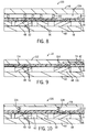
- a cross sectional side view of semiconductor press-pack illustrated in FIG. 8 , includes a POL interconnection pressed by metal posts 102 disposed within a rubber mat 104 in the package 100.
- the rubber mat 104 may include a combination of silicone rubber, or any other material which may act as a spring to distribute uniform pressure to all the die 48 in the package 100.
- the package 100 may also include spacers 56 which may be suitable for withstanding force exerted by the emitter plate 58 through the rubber mat 104.
- the spacers 56 may be compliant and may protect the die 48 from possible damage resulting from the force of the mat 104 against the layer of die 48.
- the rubber mat 104 and metal posts 102 may be replaced by a metal foam which is sufficiently compliant and provides electrical and thermal conductivity.
- FIG. 9 is an illustration of a cross-sectional side view of a press-pack semiconductor package including a porous emitter plate.
- the package 110 includes a POL structure including a copper layer 42 and a polyimide layer 44, attached to a layer of die 48 in the package 110 by an adhesive layer 46.
- a porous copper emitter plate 112 may press against the POL structure and against the die 48.
- the porous copper emitter plate 112 may be grown from the POL copper layer 42, and may be plated thick and planarized through plating (e.g., pulse plating, conventional plating, mechanical grinding, or any combination thereof).
- the emitter plate 112 may be recessed to separate the gate 116 of the device from the emitter 112, and the recessed region may be filled with an insulator 74 to provide gate insulation.
- the porosity of the emitter plate 112 may render the emitter plate 112 sufficiently compliant to make contact with the die 48 without the aid of springs or additional spacers (e.g., spring 54 and spacer 56 as in FIG. 3 ).
- the emitter plate 112 may have a porosity of approximately 25-80%.
- the emitter plate 112 may include metal foam, and may include a porous conductive metal.
- the volume of the metal foam of the emitter plate 112 may have approximately 10-95% void spaces.
- FIG. 10 A cross-sectional side view of another embodiment of a press-pack semiconductor package including copper springs grown from a POL copper layer is illustrated in FIG. 10 .
- the package 120 may include a POL copper layer 122 which grows copper springs 124 near a back portion of the die 48.
- the copper springs 124 may be grown through microfabrication or glancing angle deposition (or GLAD), and may take the form of any structure, including spring-like structures, levers, or any other structure suitable for enabling contact with the emitter plate 58. Further, any suitable metal may be used to grow the copper springs 124.
- the package 120 may also include spacers 56 disposed between the die 48 which may be compliant against force exerted by the emitter plate 58.
Landscapes
- Engineering & Computer Science (AREA)
- Microelectronics & Electronic Packaging (AREA)
- Power Engineering (AREA)
- Computer Hardware Design (AREA)
- Physics & Mathematics (AREA)
- Condensed Matter Physics & Semiconductors (AREA)
- General Physics & Mathematics (AREA)
- Die Bonding (AREA)
- Cooling Or The Like Of Semiconductors Or Solid State Devices (AREA)
Applications Claiming Priority (1)
| Application Number | Priority Date | Filing Date | Title |
|---|---|---|---|
| US12/771,892 US8531027B2 (en) | 2010-04-30 | 2010-04-30 | Press-pack module with power overlay interconnection |
Publications (2)
| Publication Number | Publication Date |
|---|---|
| EP2388817A2 true EP2388817A2 (de) | 2011-11-23 |
| EP2388817A3 EP2388817A3 (de) | 2017-11-08 |
Family
ID=44315177
Family Applications (1)
| Application Number | Title | Priority Date | Filing Date |
|---|---|---|---|
| EP11163977.9A Pending EP2388817A3 (de) | 2010-04-30 | 2011-04-27 | Presspackmodul mit Leistungsüberlagerungsverbindung |
Country Status (3)
| Country | Link |
|---|---|
| US (1) | US8531027B2 (de) |
| EP (1) | EP2388817A3 (de) |
| CN (1) | CN102237344B (de) |
Cited By (1)
| Publication number | Priority date | Publication date | Assignee | Title |
|---|---|---|---|---|
| EP2940731A1 (de) * | 2014-04-28 | 2015-11-04 | Siemens Aktiengesellschaft | Transistoranordnung für einen spannverband und spannverband mit zumindest einer solchen transistoranordnung |
Families Citing this family (28)
| Publication number | Priority date | Publication date | Assignee | Title |
|---|---|---|---|---|
| US9299630B2 (en) * | 2012-07-30 | 2016-03-29 | General Electric Company | Diffusion barrier for surface mount modules |
| US8941208B2 (en) * | 2012-07-30 | 2015-01-27 | General Electric Company | Reliable surface mount integrated power module |
| US9337163B2 (en) * | 2012-11-13 | 2016-05-10 | General Electric Company | Low profile surface mount package with isolated tab |
| US9209151B2 (en) | 2013-09-26 | 2015-12-08 | General Electric Company | Embedded semiconductor device package and method of manufacturing thereof |
| US9177943B2 (en) * | 2013-10-15 | 2015-11-03 | Ixys Corporation | Power device cassette with auxiliary emitter contact |
| US9806051B2 (en) | 2014-03-04 | 2017-10-31 | General Electric Company | Ultra-thin embedded semiconductor device package and method of manufacturing thereof |
| CN105336723B (zh) | 2014-07-28 | 2018-09-14 | 通用电气公司 | 半导体模块、半导体模块组件及半导体装置 |
| US9613843B2 (en) | 2014-10-13 | 2017-04-04 | General Electric Company | Power overlay structure having wirebonds and method of manufacturing same |
| EP3189545B1 (de) * | 2014-10-24 | 2018-05-02 | ABB Schweiz AG | Halbleitermodul und stapelanordnung von halbleitermodulen |
| US9818837B2 (en) * | 2014-12-10 | 2017-11-14 | Semiconductor Components Industries, Llc | Process of forming an electronic device having an electronic component |
| KR102543528B1 (ko) * | 2015-12-07 | 2023-06-15 | 현대모비스 주식회사 | 전력 모듈 패키지 및 그 제조방법 |
| WO2017220949A1 (en) * | 2016-06-20 | 2017-12-28 | Zhuzhou Crrc Times Electric Co. Ltd. | A semiconductor device sub-assembly |
| WO2018129272A1 (en) * | 2017-01-06 | 2018-07-12 | Massachusetts Institute Of Technology | Nanocomposite surfaces with electrically switchable adhesion |
| US10541209B2 (en) | 2017-08-03 | 2020-01-21 | General Electric Company | Electronics package including integrated electromagnetic interference shield and method of manufacturing thereof |
| US10541153B2 (en) | 2017-08-03 | 2020-01-21 | General Electric Company | Electronics package with integrated interconnect structure and method of manufacturing thereof |
| US10804115B2 (en) | 2017-08-03 | 2020-10-13 | General Electric Company | Electronics package with integrated interconnect structure and method of manufacturing thereof |
| CN108281405B (zh) * | 2017-12-11 | 2019-08-27 | 全球能源互联网研究院有限公司 | 一种功率器件封装结构及方法 |
| CN108281406B (zh) * | 2017-12-11 | 2020-02-07 | 全球能源互联网研究院有限公司 | 一种功率器件封装结构及其制造方法 |
| CN108376702B (zh) * | 2018-01-07 | 2022-06-21 | 北京工业大学 | 一种用于压接式igbt模块的弹性多孔结构电极 |
| US10778112B2 (en) * | 2018-04-04 | 2020-09-15 | General Electric Company | DFIG converter with active filter |
| CN108649022B (zh) * | 2018-05-17 | 2020-04-10 | 江苏芯澄半导体有限公司 | 一种宽禁带半导体碳化硅功率模块高温封装结构 |
| CN108682655B (zh) * | 2018-05-17 | 2020-01-17 | 江苏芯澄半导体有限公司 | 一种宽禁带半导体碳化硅功率模块高温封装方法 |
| CN112385037A (zh) * | 2018-07-11 | 2021-02-19 | 丹尼克斯半导体有限公司 | 半导体器件子组件 |
| CN110912421B (zh) * | 2018-09-14 | 2023-04-14 | 通用电气航空系统有限责任公司 | 电力覆盖架构 |
| US10985537B2 (en) | 2018-09-14 | 2021-04-20 | Ge Aviation Systems Llc | Power overlay architecture |
| CN111162015A (zh) * | 2019-12-20 | 2020-05-15 | 珠海格力电器股份有限公司 | 一种智能功率模块及封装方法 |
| US11398445B2 (en) | 2020-05-29 | 2022-07-26 | General Electric Company | Mechanical punched via formation in electronics package and electronics package formed thereby |
| JP3243789U (ja) | 2020-10-15 | 2023-09-21 | ヒタチ・エナジー・スウィツァーランド・アクチェンゲゼルシャフト | パワー半導体モジュール |
Family Cites Families (15)
| Publication number | Priority date | Publication date | Assignee | Title |
|---|---|---|---|---|
| JP3258200B2 (ja) * | 1995-05-31 | 2002-02-18 | 株式会社東芝 | 圧接型半導体装置 |
| US5637922A (en) | 1994-02-07 | 1997-06-10 | General Electric Company | Wireless radio frequency power semiconductor devices using high density interconnect |
| US5808874A (en) * | 1996-05-02 | 1998-09-15 | Tessera, Inc. | Microelectronic connections with liquid conductive elements |
| DE19732738A1 (de) * | 1997-07-30 | 1999-02-04 | Asea Brown Boveri | Leistungshalbleiterbauelemente mit druckausgleichender Kontaktplatte |
| CN1236982A (zh) * | 1998-01-22 | 1999-12-01 | 株式会社日立制作所 | 压力接触型半导体器件及其转换器 |
| US6331476B1 (en) * | 1998-05-26 | 2001-12-18 | Mausushita Electric Industrial Co., Ltd. | Thin film transistor and producing method thereof |
| US6306680B1 (en) | 1999-02-22 | 2001-10-23 | General Electric Company | Power overlay chip scale packages for discrete power devices |
| US6242282B1 (en) | 1999-10-04 | 2001-06-05 | General Electric Company | Circuit chip package and fabrication method |
| US6232151B1 (en) * | 1999-11-01 | 2001-05-15 | General Electric Company | Power electronic module packaging |
| US7095111B2 (en) * | 2003-03-31 | 2006-08-22 | Intel Corporation | Package with integrated wick layer and method for heat removal |
| US7232710B2 (en) * | 2003-12-17 | 2007-06-19 | Ut-Battelle, Llc | Method of making cascaded die mountings with springs-loaded contact-bond options |
| DE102004018477B4 (de) * | 2004-04-16 | 2008-08-21 | Infineon Technologies Ag | Halbleitermodul |
| JP2006269148A (ja) * | 2005-03-23 | 2006-10-05 | Alps Electric Co Ltd | スパイラル接触子 |
| US7262444B2 (en) | 2005-08-17 | 2007-08-28 | General Electric Company | Power semiconductor packaging method and structure |
| DE102007036566A1 (de) * | 2007-08-03 | 2009-02-19 | Siemens Ag | Federkontaktierung von elektrischen Kontaktflächen eines elektronischen Bauteils |
-
2010
- 2010-04-30 US US12/771,892 patent/US8531027B2/en active Active
-
2011
- 2011-04-27 EP EP11163977.9A patent/EP2388817A3/de active Pending
- 2011-04-29 CN CN201110119566.2A patent/CN102237344B/zh active Active
Non-Patent Citations (1)
| Title |
|---|
| None |
Cited By (1)
| Publication number | Priority date | Publication date | Assignee | Title |
|---|---|---|---|---|
| EP2940731A1 (de) * | 2014-04-28 | 2015-11-04 | Siemens Aktiengesellschaft | Transistoranordnung für einen spannverband und spannverband mit zumindest einer solchen transistoranordnung |
Also Published As
| Publication number | Publication date |
|---|---|
| EP2388817A3 (de) | 2017-11-08 |
| US8531027B2 (en) | 2013-09-10 |
| US20110266665A1 (en) | 2011-11-03 |
| CN102237344B (zh) | 2016-08-24 |
| CN102237344A (zh) | 2011-11-09 |
Similar Documents
| Publication | Publication Date | Title |
|---|---|---|
| US8531027B2 (en) | Press-pack module with power overlay interconnection | |
| Lee et al. | A review of SiC power module packaging technologies: Challenges, advances, and emerging issues | |
| US10283436B2 (en) | Power electronics module with first and second coolers | |
| Abebe et al. | Integrated motor drives: state of the art and future trends | |
| EP2722879B1 (de) | Halbleitereinheit und halbleitervorrichtung damit | |
| CN108172617B (zh) | 一种圆形大尺寸igbt芯片压接封装结构及制造方法 | |
| CN110199388A (zh) | 用于并联功率装置的具有低电感和快速切换的高功率多层模块 | |
| US11081422B2 (en) | Self-healing PDMS encapsulation and repair of power modules | |
| US20080277687A1 (en) | High power density switch module with improved thermal management and packaging | |
| US20130020672A1 (en) | System and Method for Packaging of High-Voltage Semiconductor Devices | |
| WO2017138402A1 (ja) | 半導体装置、パワーモジュール、およびその製造方法 | |
| JP2012015222A (ja) | 半導体装置 | |
| US10147699B2 (en) | Pressure contact type semiconductor apparatus | |
| JP3617306B2 (ja) | 加圧接触型半導体装置、及びこれを用いた変換器 | |
| US20240153862A1 (en) | Double-side cooled power modules with sintered-silver interposers | |
| Zhang et al. | Packaging of an 8-kV silicon carbide diode module with double-side cooling and sintered-silver joints | |
| EP3460840B1 (de) | Vorrichtungen zum befestigen und abdichten einer halbleiterkühlstruktur | |
| WO2021181831A1 (ja) | 電気回路体、電力変換装置、および電気回路体の製造方法 | |
| EP3410481A1 (de) | Leistungshalbleiter-chipmodul | |
| Lu et al. | Review of Double Sided Cooling Power Modules for Driving Electric Vehicles | |
| WO2000008683A1 (en) | Flat semiconductor device, method for manufacturing the same, and converter comprising the same | |
| US20220352137A1 (en) | High power density 3d semiconductor module packaging | |
| Ang et al. | Packaging issues for high-voltage power electronic modules | |
| EP3065164A1 (de) | Leistungshalbleiteranordnung und Verfahren zur Erzeugung einer Leistungshalbleiteranordnung | |
| CN211788994U (zh) | 功率模块的封装结构和电子设备 |
Legal Events
| Date | Code | Title | Description |
|---|---|---|---|
| AK | Designated contracting states |
Kind code of ref document: A2 Designated state(s): AL AT BE BG CH CY CZ DE DK EE ES FI FR GB GR HR HU IE IS IT LI LT LU LV MC MK MT NL NO PL PT RO RS SE SI SK SM TR |
|
| AX | Request for extension of the european patent |
Extension state: BA ME |
|
| PUAI | Public reference made under article 153(3) epc to a published international application that has entered the european phase |
Free format text: ORIGINAL CODE: 0009012 |
|
| RIC1 | Information provided on ipc code assigned before grant |
Ipc: H01L 25/07 20060101ALI20170502BHEP Ipc: H01L 23/48 20060101AFI20170502BHEP |
|
| PUAL | Search report despatched |
Free format text: ORIGINAL CODE: 0009013 |
|
| AK | Designated contracting states |
Kind code of ref document: A3 Designated state(s): AL AT BE BG CH CY CZ DE DK EE ES FI FR GB GR HR HU IE IS IT LI LT LU LV MC MK MT NL NO PL PT RO RS SE SI SK SM TR |
|
| AX | Request for extension of the european patent |
Extension state: BA ME |
|
| RIC1 | Information provided on ipc code assigned before grant |
Ipc: H01L 25/07 20060101ALI20171004BHEP Ipc: H01L 23/48 20060101AFI20171004BHEP |
|
| STAA | Information on the status of an ep patent application or granted ep patent |
Free format text: STATUS: REQUEST FOR EXAMINATION WAS MADE |
|
| 17P | Request for examination filed |
Effective date: 20180508 |
|
| RBV | Designated contracting states (corrected) |
Designated state(s): AL AT BE BG CH CY CZ DE DK EE ES FI FR GB GR HR HU IE IS IT LI LT LU LV MC MK MT NL NO PL PT RO RS SE SI SK SM TR |
|
| STAA | Information on the status of an ep patent application or granted ep patent |
Free format text: STATUS: EXAMINATION IS IN PROGRESS |
|
| 17Q | First examination report despatched |
Effective date: 20210305 |
|
| STAA | Information on the status of an ep patent application or granted ep patent |
Free format text: STATUS: EXAMINATION IS IN PROGRESS |
|
| P01 | Opt-out of the competence of the unified patent court (upc) registered |
Effective date: 20230530 |
|
| RAP1 | Party data changed (applicant data changed or rights of an application transferred) |
Owner name: GENERAL ELECTRIC RENOVABLES ESPANA, S.L. |