EP2388423A2 - Antrieb für einen Flügel einer Tür oder eines Fensters - Google Patents
Antrieb für einen Flügel einer Tür oder eines Fensters Download PDFInfo
- Publication number
- EP2388423A2 EP2388423A2 EP11166150A EP11166150A EP2388423A2 EP 2388423 A2 EP2388423 A2 EP 2388423A2 EP 11166150 A EP11166150 A EP 11166150A EP 11166150 A EP11166150 A EP 11166150A EP 2388423 A2 EP2388423 A2 EP 2388423A2
- Authority
- EP
- European Patent Office
- Prior art keywords
- hydraulic
- drive
- hydraulic reservoir
- reservoir
- hydraulic fluid
- Prior art date
- Legal status (The legal status is an assumption and is not a legal conclusion. Google has not performed a legal analysis and makes no representation as to the accuracy of the status listed.)
- Granted
Links
Images

Classifications
-
- E—FIXED CONSTRUCTIONS
- E05—LOCKS; KEYS; WINDOW OR DOOR FITTINGS; SAFES
- E05F—DEVICES FOR MOVING WINGS INTO OPEN OR CLOSED POSITION; CHECKS FOR WINGS; WING FITTINGS NOT OTHERWISE PROVIDED FOR, CONCERNED WITH THE FUNCTIONING OF THE WING
- E05F3/00—Closers or openers with braking devices, e.g. checks; Construction of pneumatic or liquid braking devices
- E05F3/04—Closers or openers with braking devices, e.g. checks; Construction of pneumatic or liquid braking devices with liquid piston brakes
- E05F3/10—Closers or openers with braking devices, e.g. checks; Construction of pneumatic or liquid braking devices with liquid piston brakes with a spring, other than a torsion spring, and a piston, the axes of which are the same or lie in the same direction
- E05F3/102—Closers or openers with braking devices, e.g. checks; Construction of pneumatic or liquid braking devices with liquid piston brakes with a spring, other than a torsion spring, and a piston, the axes of which are the same or lie in the same direction with rack-and-pinion transmission between driving shaft and piston within the closer housing
-
- E—FIXED CONSTRUCTIONS
- E05—LOCKS; KEYS; WINDOW OR DOOR FITTINGS; SAFES
- E05F—DEVICES FOR MOVING WINGS INTO OPEN OR CLOSED POSITION; CHECKS FOR WINGS; WING FITTINGS NOT OTHERWISE PROVIDED FOR, CONCERNED WITH THE FUNCTIONING OF THE WING
- E05F3/00—Closers or openers with braking devices, e.g. checks; Construction of pneumatic or liquid braking devices
- E05F3/04—Closers or openers with braking devices, e.g. checks; Construction of pneumatic or liquid braking devices with liquid piston brakes
- E05F3/10—Closers or openers with braking devices, e.g. checks; Construction of pneumatic or liquid braking devices with liquid piston brakes with a spring, other than a torsion spring, and a piston, the axes of which are the same or lie in the same direction
-
- E—FIXED CONSTRUCTIONS
- E05—LOCKS; KEYS; WINDOW OR DOOR FITTINGS; SAFES
- E05F—DEVICES FOR MOVING WINGS INTO OPEN OR CLOSED POSITION; CHECKS FOR WINGS; WING FITTINGS NOT OTHERWISE PROVIDED FOR, CONCERNED WITH THE FUNCTIONING OF THE WING
- E05F3/00—Closers or openers with braking devices, e.g. checks; Construction of pneumatic or liquid braking devices
- E05F3/04—Closers or openers with braking devices, e.g. checks; Construction of pneumatic or liquid braking devices with liquid piston brakes
- E05F3/12—Special devices controlling the circulation of the liquid, e.g. valve arrangement
-
- E—FIXED CONSTRUCTIONS
- E05—LOCKS; KEYS; WINDOW OR DOOR FITTINGS; SAFES
- E05F—DEVICES FOR MOVING WINGS INTO OPEN OR CLOSED POSITION; CHECKS FOR WINGS; WING FITTINGS NOT OTHERWISE PROVIDED FOR, CONCERNED WITH THE FUNCTIONING OF THE WING
- E05F3/00—Closers or openers with braking devices, e.g. checks; Construction of pneumatic or liquid braking devices
- E05F3/22—Additional arrangements for closers, e.g. for holding the wing in opened or other position
- E05F3/227—Additional arrangements for closers, e.g. for holding the wing in opened or other position mounted at the top of wings, e.g. details related to closer housings, covers, end caps or rails therefor
-
- E—FIXED CONSTRUCTIONS
- E05—LOCKS; KEYS; WINDOW OR DOOR FITTINGS; SAFES
- E05F—DEVICES FOR MOVING WINGS INTO OPEN OR CLOSED POSITION; CHECKS FOR WINGS; WING FITTINGS NOT OTHERWISE PROVIDED FOR, CONCERNED WITH THE FUNCTIONING OF THE WING
- E05F15/00—Power-operated mechanisms for wings
- E05F15/50—Power-operated mechanisms for wings using fluid-pressure actuators
- E05F15/53—Power-operated mechanisms for wings using fluid-pressure actuators for swinging wings
-
- E—FIXED CONSTRUCTIONS
- E05—LOCKS; KEYS; WINDOW OR DOOR FITTINGS; SAFES
- E05Y—INDEXING SCHEME ASSOCIATED WITH SUBCLASSES E05D AND E05F, RELATING TO CONSTRUCTION ELEMENTS, ELECTRIC CONTROL, POWER SUPPLY, POWER SIGNAL OR TRANSMISSION, USER INTERFACES, MOUNTING OR COUPLING, DETAILS, ACCESSORIES, AUXILIARY OPERATIONS NOT OTHERWISE PROVIDED FOR, APPLICATION THEREOF
- E05Y2201/00—Constructional elements; Accessories therefor
- E05Y2201/10—Covers; Housings
-
- E—FIXED CONSTRUCTIONS
- E05—LOCKS; KEYS; WINDOW OR DOOR FITTINGS; SAFES
- E05Y—INDEXING SCHEME ASSOCIATED WITH SUBCLASSES E05D AND E05F, RELATING TO CONSTRUCTION ELEMENTS, ELECTRIC CONTROL, POWER SUPPLY, POWER SIGNAL OR TRANSMISSION, USER INTERFACES, MOUNTING OR COUPLING, DETAILS, ACCESSORIES, AUXILIARY OPERATIONS NOT OTHERWISE PROVIDED FOR, APPLICATION THEREOF
- E05Y2201/00—Constructional elements; Accessories therefor
- E05Y2201/40—Motors; Magnets; Springs; Weights; Accessories therefor
- E05Y2201/43—Motors
- E05Y2201/448—Fluid motors; Details thereof
-
- E—FIXED CONSTRUCTIONS
- E05—LOCKS; KEYS; WINDOW OR DOOR FITTINGS; SAFES
- E05Y—INDEXING SCHEME ASSOCIATED WITH SUBCLASSES E05D AND E05F, RELATING TO CONSTRUCTION ELEMENTS, ELECTRIC CONTROL, POWER SUPPLY, POWER SIGNAL OR TRANSMISSION, USER INTERFACES, MOUNTING OR COUPLING, DETAILS, ACCESSORIES, AUXILIARY OPERATIONS NOT OTHERWISE PROVIDED FOR, APPLICATION THEREOF
- E05Y2800/00—Details, accessories and auxiliary operations not otherwise provided for
-
- E—FIXED CONSTRUCTIONS
- E05—LOCKS; KEYS; WINDOW OR DOOR FITTINGS; SAFES
- E05Y—INDEXING SCHEME ASSOCIATED WITH SUBCLASSES E05D AND E05F, RELATING TO CONSTRUCTION ELEMENTS, ELECTRIC CONTROL, POWER SUPPLY, POWER SIGNAL OR TRANSMISSION, USER INTERFACES, MOUNTING OR COUPLING, DETAILS, ACCESSORIES, AUXILIARY OPERATIONS NOT OTHERWISE PROVIDED FOR, APPLICATION THEREOF
- E05Y2800/00—Details, accessories and auxiliary operations not otherwise provided for
- E05Y2800/15—Applicability
- E05Y2800/17—Universally applicable
- E05Y2800/172—Universally applicable on different wing or frame locations
-
- E—FIXED CONSTRUCTIONS
- E05—LOCKS; KEYS; WINDOW OR DOOR FITTINGS; SAFES
- E05Y—INDEXING SCHEME ASSOCIATED WITH SUBCLASSES E05D AND E05F, RELATING TO CONSTRUCTION ELEMENTS, ELECTRIC CONTROL, POWER SUPPLY, POWER SIGNAL OR TRANSMISSION, USER INTERFACES, MOUNTING OR COUPLING, DETAILS, ACCESSORIES, AUXILIARY OPERATIONS NOT OTHERWISE PROVIDED FOR, APPLICATION THEREOF
- E05Y2900/00—Application of doors, windows, wings or fittings thereof
- E05Y2900/10—Application of doors, windows, wings or fittings thereof for buildings or parts thereof
- E05Y2900/13—Type of wing
- E05Y2900/132—Doors
Definitions
- the invention relates to a drive for a wing of a door or a window according to claim 1.
- an electro-hydraulic drive for wings of doors with a cylinder-piston unit whose piston working space is connected on the inlet side to the pressure side of an electrically driven hydraulic pump and the outlet side to a hydraulic reservoir.
- the piston working chamber accommodates a piston which is drivingly coupled to the vane and acted upon by a closing spring in the closing direction of the vane.
- a pressure compensation element can be provided which receives volume changes of the hydraulic fluid.
- a drive for a wing of a window or a door comprising a housing and a spring-loaded piston arranged in the housing.
- the housing is filled with a hydraulic fluid, which serves to control the piston movement when opening and closing the wing, including overflow and valves are provided.
- a gas volume enclosed by an elastic enveloping body is provided on whose lateral surface the pressure of the hydraulic fluid acts.
- a disadvantage is the complex sealing of the elastic enveloping body, which could possibly also be leaking due to aging.
- the invention has for its object to provide a simple, reliable pressure compensation device for a drive for a wing of a door or a window.
- Electro-hydraulic drives for the wings of a door or a window can be designed as drives arranged on the door frame or on the wing of the door or of the window, and have a toothed piston, in the teeth of which a pinion of an output shaft meshes.
- a linkage or guided in a slide sliding arm is arranged, which cooperates with the wing for opening and closing.
- the piston is acted upon in the filled with the hydraulic fluid housing with a spring.
- overflow channels and valves for the hydraulic fluid are arranged in the drive, which serve to control the behavior of the drive.
- the proposed pressure compensation device for compensating temperature-induced volume change of the hydraulic fluid is arranged in the hydraulic reservoir.
- the hydraulic pump sucks the hydraulic fluid out of the hydraulic reservoir.
- the longitudinal extent of the hydraulic reservoir is aligned at least approximately horizontally.
- a flexible intake hose protrudes into the hydraulic reservoir, which at its open end has an at least as heavy a nozzle that this nozzle always comes to rest on the bottom of the hydraulic reservoir.
- a gas volume for example air, is provided which, due to its lower density, is located above the opening hydraulic passages relative to the hydraulic fluid. As a result, the gas volume in the hydraulic reservoir is included. Since gases are compressible or expandable, a temperature-induced change in the volume of the hydraulic fluid is compensated.
- the pressure compensation device acts independently of position, whereby the drive is suitable for alternative installation methods. This position independence is important in an alternative mounting on the hinge side or the hinge opposite side of a door or in the optional mounting on the wing or on the frame of the door, since the drive must also be mounted rotated by 180 °.
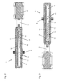
- Fig. 1 is an electro-hydraulically formed drive 1 shown in section.
- the drive 1 comprises a housing 2 with a displaceably guided in the cylindrical receiving space 5 piston 7, in the toothing of the pinion of an output shaft 8 meshes.
- a closing spring 6 is arranged axially between an end face of the piston 3 and a right end of the housing 2.
- the receiving space 5 of the housing 2 is completely filled with hydraulic fluid 9, since the hydraulic system of the drive 1 was vented during filling.
- 2 hydraulic channels 10 are provided in the housing.
- the drive 1 is further provided with a hydraulic pump 3 and a motor 4, whereby an automatic operation is possible by using control elements for the recognition of persons.
- the intake region of the hydraulic pump 3 is located in a hydraulic reservoir 11, which likewise communicates with the receiving chamber 5 via hydraulic channels 10. In the assembled state of the drive 1, the longitudinal extent of the hydraulic reservoir 11 is aligned at least approximately horizontally.
- a lever arm or a linkage is arranged for opening and closing the wing of the door, which is connected thereto in a conventional manner with the wing.
- the piston 7 is displaced in the direction of the closing spring 6 by means of the motor 4 driven by the hydraulic pump 3, whereby it is compressed.
- the energy stored thereby in the closing spring 6 is in turn available again for closing the leaf of the door, for which purpose no operation by the motor 4 and the hydraulic pump 3 is required.
- a suction element 13 is arranged at the bottom of the hydraulic reservoir 11 for the removal of hydraulic fluid 9.
- the suction element 13 is arranged at a connection of the hydraulic pump 3 and comprises a hose 14 and a spigot 15.
- the spout 15 may also be directly articulated, for example by means of a ball joint, connected to the connection of the hydraulic pump 3.
- a gas volume 12 is provided in the hydraulic reservoir 11.
- Fig. 2 is one of two possible ways of mounting shown, as required for example for an alternative mounting of the drive 1 on the tape opposite side or the hinge side or even with double-leaf doors.
- the second possible method of installation is a 180 ° rotated assembly, as in the Fig. 3 is shown.
- the engine 4 is then opposite to in Fig. 2 shown left arrangement, which is possible through the continuous output shaft 8, which allows a connection possibility for the linkage or the sliding arm for connecting the wing of the door on both sides of the housing 2.
- the opening into the hydraulic reservoir 11 hydraulic channels 10 are arranged approximately centrally in the hydraulic reservoir 11.
- the gas volume 12 located above the hydraulic fluid 9 is selected such that it reaches at most as far as the hydraulic channels 10 at the lowest intended operating temperature. This condition is in the Fig. 3 shown.
- Fig. 2 shows a state in contrast higher temperature, wherein the volume of the hydraulic fluid 9 has increased, which is compensated by compression of the gas volume 12.
- the suction element 13 is designed so that it always drops with its open end to the bottom of the hydraulic reservoir 11.
- the suction element is advantageous 13 designed to be flexible, so that at least the nozzle 15 regardless of the position of the drive 1 according to the mounting always in the hydraulic fluid 9 remains, whereby no gas from the gas volume 12 is sucked by the hydraulic pump 3 or passes through the hydraulic channels 10 into the receiving space 5 ,
- the comparatively heavy nozzle 15, which may be made of metal, for example, is fixed to a flexible hose 14, whereby the nozzle 15, following gravity, comes to rest in the hydraulic fluid 9 at the bottom of the hydraulic reservoir 11 for the removal of hydraulic fluid 9.
- the ratio of hose 14 and nozzle 15 is not fixed.
- the nozzle 15 may also be arranged as a short tail on a then slightly longer hose 14.
Landscapes
- Power-Operated Mechanisms For Wings (AREA)
- Fluid-Damping Devices (AREA)
Abstract
Description
- Die Erfindung betrifft einen Antrieb für einen Flügel einer Tür oder eines Fensters nach Anspruch 1.
- Aus der
DE 32 02 966 C2 ist ein elektrohydraulischer Antrieb für Flügel von Türen bekannt, mit einem Zylinder-Kolben-Aggregat, dessen Kolbenarbeitsraum einlassseitig an die Druckseite einer elektrisch angetriebenen Hydraulikpumpe und auslassseitig an ein Hydraulikreservoir angeschlossen ist. Der Kolbenarbeitsraum nimmt einen mit dem Flügel antriebsmäßig gekoppelten und mittels Schließfeder in Schließrichtung des Flügels beaufschlagten Kolben verschiebbar auf. Durch Einschalten der Hydraulikpumpe wird der Kolben gegen die Kraft der Schließfeder vorgeschoben, wodurch der Flügel in Offenstellung gelangt. Im Hydraulikreservoir kann ein Druckausgleichselement vorgesehen sein, das Volumenänderungen der Hydraulikflüssigkeit aufnimmt. - Aus der
EP 2 075 398 A2 ist ein Antrieb für einen Flügel eines Fensters oder einer Tür bekannt, mit einem Gehäuse und einem in dem Gehäuse angeordneten, federbeaufschlagten Kolben. Das Gehäuse ist mit einer Hydraulikflüssigkeit gefüllt, die zur Steuerung der Kolbenbewegung beim Öffnen und Schließen des Flügels dient, wozu Überströmkanäle und Ventile vorgesehen sind. Zum Ausgleich der Volumenänderung der Hydraulikflüssigkeit, z.B. infolge Wärmeausdehnung, ist ein von einem elastischen Hüllkörper umschlossenes Gasvolumen vorgesehen, auf dessen Mantelfläche der Druck der Hydraulikflüssigkeit wirkt. Nachteilig ist die aufwändige Abdichtung des elastischen Hüllkörpers, der möglicherweise auch durch Alterung undicht werden könnte. - Aus der
DE 34 11 189 A1 ist ein als Türschließer ausgebildeter Antrieb bekannt, mit einem auf einer Hubkurvenscheibe abgestützten Dämpfungskolben, welcher eine als Speicherzylinder dienende Aushöhlung aufweist, in welcher ein Druckausgleichskolben angeordnet ist, der in Richtung auf die Aushöhlung des Dämpfungskolbens unter Belastung einer Druckfeder steht und eine Druckausgleichseinrichtung für das im Türschließer vorhandene Druckmittel bildet. Bei einem Druckanstieg innerhalb des Türantriebs wird der Druckausgleichskolben gegen die Druckfeder verschoben. Problematisch ist dabei die Abdichtung des Luftvolumens in der Aushöhlung des Dämpfungskolbens durch den Druckausgleichskolben. - Der Erfindung liegt die Aufgabe zugrunde, eine einfache, zuverlässige Druckausgleichseinrichtung für einen Antrieb für einen Flügel einer Tür oder eines Fensters zu schaffen.
- Die Aufgabe wird durch die Merkmale des Patentanspruchs 1 gelöst.
- Die Unteransprüche bilden vorteilhafte Ausgestaltungsmöglichkeiten der Erfindung.
- Elektrohydraulische Antriebe für Flügel einer Tür oder eines Fensters können als am Türrahmen oder auf dem Flügel der Tür bzw. des Fensters angeordnete Antriebe ausgebildet sein, und einen verzahnten Kolben aufweisen, in dessen Verzahnung ein Ritzel einer Abtriebswelle kämmt. An der Abtriebswelle ist dabei in bekannter Weise ein Gestänge oder ein in einer Gleitschiene geführter Gleitarm angeordnet, der mit dem Flügel zum Öffnen und Schließen zusammenwirkt. Der Kolben ist im mit der Hydraulikflüssigkeit gefüllten Gehäuse mit einer Feder beaufschlagt. Weiterhin sind Überströmkanäle und Ventile für die Hydraulikflüssigkeit im Antrieb angeordnet, welche zur Steuerung des Verhaltens des Antriebs dienen.
- Die vorgeschlagene Druckausgleichseinrichtung zum Ausgleich temperaturbedingter Volumenänderung der Hydraulikflüssigkeit ist im Hydraulikreservoir angeordnet.
- Aus dem Hydraulikreservoir heraus saugt die Hydraulikpumpe die Hydraulikflüssigkeit an. In montiertem Zustand des Antriebs ist die Längserstreckung des Hydraulikreservoirs zumindest annähernd waagrecht ausgerichtet. Zum Ansaugen der Hydraulikflüssigkeit ragt in das Hydraulikreservoir ein flexibler Ansaugschlauch hinein, der an seinem offenen Ende einen zumindest so schweren Stutzen aufweist, dass dieser Stutzen stets am Grund des Hydraulikreservoirs zu liegen kommt. Die Rückführung der Hydraulikflüssigkeit aus dem Aufnahmeraum von Kolben und Schließfeder in das Hydraulikreservoir hinein erfolgt über einen oder mehrere Hydraulikkanäle, die mittig, in Bezug auf die vertikale Erstreckung, in das Hydraulikreservoir münden. Im Hydraulikreservoir ist ein Gasvolumen, beispielsweise Luft, vorgesehen, das sich, aufgrund seiner geringeren Dichte, gegenüber der Hydraulikflüssigkeit oberhalb der einmündenden Hydraulikkanäle befindet. Dadurch ist das Gasvolumen im Hydraulikreservoir eingeschlossen. Da Gase kompressibel bzw. expandierbar sind, wird eine temperaturbedingte Änderung des Volumens der Hydraulikflüssigkeit kompensiert.
- Die Druckausgleichseinrichtung wirkt lageunabhängig, wodurch der Antrieb für alternative Montageweisen geeignet ist. Diese Lageunabhängigkeit ist bei einer alternativen Montage auf der Bandseite bzw. der Bandgegenseite einer Tür oder bei der wahlweisen Montage auf dem Flügel oder auf dem Rahmen der Tür wichtig, da der Antrieb dabei auch um 180° gedreht anbaubar sein muss.
- Im Nachfolgenden wird ein Ausführungsbeispiel in der Zeichnung anhand der Figuren näher erläutert.
- Dabei zeigen:
- Fig. 1
- einen waagrechten Längsschnitt durch einen elektrohydraulischen Antrieb;
- Fig. 2
- einen Längsschnitt durch das Hydraulikreservoir in einer ersten Montageweise des Antriebs;
- Fig. 3
- einen Längsschnitt durch das Hydraulikreservoir in einer zweiten Montageweise des Antriebs.
- In
Fig. 1 ist ein elektrohydraulisch ausgebildeter Antrieb 1 im Schnitt dargestellt. Der Antrieb 1 umfasst ein Gehäuse 2 mit einem im zylindrischen Aufnahmeraum 5 verschiebbar geführten Kolben 7, in dessen Verzahnung das Ritzel einer Abtriebswelle 8 kämmt. Eine Schließfeder 6 ist axial zwischen einer Stirnfläche des Kolbens 3 und einem rechten Ende des Gehäuses 2 angeordnet. - Der Aufnahmeraum 5 des Gehäuses 2 ist vollständig mit Hydraulikflüssigkeit 9 gefüllt, da das Hydrauliksystem des Antriebs 1 während des Befüllens entlüftet wurde.
- Durch das Entlüften wird ein durch ein im Aufnahmeraum 5 des Gehäuses 2 ansonsten vorhandenes Luftpolster bedingtes, für den Bediener nachteiliges "Durchfallen" des Flügels der Tür verhindert. D.h. nachteilig wäre dann am Flügel durch das komprimierbare Luftpolster zunächst kein oder nur ein sehr geringer Widerstand spürbar, bis das Luftpolster so weit komprimiert ist, dass die Hydraulik des Antriebs wirksam wird. Durch das fehlende Luftpolster bei vollständiger Befüllung mit Hydraulikflüssigkeit, erfolgt jedoch bei einer Temperaturerhöhung nachteilig ein Druckanstieg im Gehäuse 2 des Antriebs 1.
- Damit der Kolben 3 seine Verschiebebewegung im Gehäuse 2 unter Dämpfung durch die Hydraulikflüssigkeit 9 ausführen kann, sind im Gehäuse 2 Hydraulikkanäle 10 vorgesehen. Es können auch weitere Hydraulikkanäle 10 vorgesehen sein, in denen Ventile zur Steuerung des Verhaltens des Antriebs 1 angeordnet sein können. Der Antrieb 1 ist weiterhin mit einer Hydraulikpumpe 3 und einem Motor 4 versehen, wodurch unter Verwendung von Ansteuerelementen zur Personenerkennung ein automatischer Betrieb möglich ist. Der Ansaugbereich der Hydraulikpumpe 3 befindet sich in einem Hydraulikreservoir 11, das ebenfalls über Hydraulikkanäle 10 mit dem Aufnahmeraum 5 in Verbindung steht. In montiertem Zustand des Antriebs 1 ist die Längserstreckung des Hydraulikreservoirs 11 zumindest annähernd waagrecht ausgerichtet.
- An der Abtriebswelle 8 des Antriebs 1 ist zum Öffnen und Schließen des Flügels der Tür ein Hebelarm bzw. ein Gestänge angeordnet, das dazu in an sich bekannter Weise mit dem Flügel verbunden ist.
- Zum Öffnen der Tür wird durch die mittels des Motors 4 angetriebene Hydraulikpumpe 3 der Kolben 7 in Richtung auf die Schließfeder 6 verschoben, wodurch diese komprimiert wird. Die dadurch in der Schließfeder 6 gespeicherte Energie steht umgekehrt zum Schließen des Flügels der Tür wieder zur Verfügung, wozu kein Betrieb durch den Motor 4 und die Hydraulikpumpe 3 erforderlich ist.
- In
Fig. 2 ist das Hydraulikreservoir 11 im Längsschnitt dargestellt. Im Hydraulikreservoir 11 ist ein Ansaugelement 13 am Grund des Hydraulikreservoirs 11 zur Entnahme von Hydraulikflüssigkeit 9 angeordnet. Das Ansaugelement 13 ist an einem Anschluss der Hydraulikpumpe 3 angeordnet und umfasst einen Schlauch 14 und einen Stutzen 15. Alternativ kann der Stutzen 15 auch direkt gelenkig, beispielsweise mittels eines Kugelgelenks, am Anschluss der Hydraulikpumpe 3 angeschlossen sein. Zur Kompensation des Druckanstiegs ist in dem Hydraulikreservoir 11 ein Gasvolumen 12 vorgesehen. - In der
Fig. 2 ist eine von zwei möglichen Montageweisen gezeigt, wie diese beispielsweise für eine alternative Montage des Antriebs 1 auf der Bandgegenseite bzw. der Bandseite oder auch bei zweiflügeligen Türen erforderlich ist. Die zweite mögliche Montageweise ist eine um 180° gedrehte Montage, wie diese in derFig. 3 dargestellt ist. Der Motor 4 befindet sich dann gegenüber der inFig. 2 gezeigten Anordnung links, was durch die durchgehende Abtriebswelle 8, die eine Anschlussmöglichkeit für das Gestänge bzw. den Gleitarm zur Anbindung des Flügels der Tür beiderseits des Gehäuses 2 erlaubt, möglich ist. - Die in das Hydraulikreservoir 11 einmündenden Hydraulikkanäle 10 sind in etwa mittig im Hydraulikreservoir 11 angeordnet. Das sich oberhalb der Hydraulikflüssigkeit 9 befindende Gasvolumen 12 ist so gewählt, dass es bei niedrigster vorgesehener Betriebstemperatur maximal bis an die Hydraulikkanäle 10 heranreicht. Dieser Zustand ist in der
Fig. 3 gezeigt.Fig. 2 zeigt einen Zustand, bei demgegenüber höherer Temperatur, wobei das Volumen der Hydraulikflüssigkeit 9 zugenommen hat, was durch Kompression des Gasvolumens 12 kompensiert ist. - Das Ansaugelement 13 ist so ausgebildet, dass es mit seinem offenen Ende stets auf den Grund des Hydraulikreservoirs 11 absinkt. Vorteilhaft ist das Ansaugelement 13 dazu flexibel ausgebildet, sodass zumindest dessen Stutzen 15 unabhängig von der Lage des Antriebs 1 entsprechend der Montageweise immer in der Hydraulikflüssigkeit 9 verbleibt, wodurch kein Gas aus dem Gasvolumen 12 durch die Hydraulikpumpe 3 angesaugt wird oder über die Hydraulikkanäle 10 in den Aufnahmeraum 5 gelangt. Dazu ist der vergleichsweise schwere Stutzen 15, der beispielsweise aus Metall sein kann, an einem flexiblen Schlauch 14 festgelegt, wodurch der Stutzen 15, der Schwerkraft folgend, in der Hydraulikflüssigkeit 9 auf dem Grund des Hydraulikreservoirs 11 zur Entnahme von Hydraulikflüssigkeit 9 zu liegen kommt.
- Das Verhältnis von Schlauch 14 und Stutzen 15 ist dabei nicht festgelegt. Der Stutzen 15 kann auch als kurzes Endstück an einem dann etwas längeren Schlauch 14 angeordnet sein.
-
- 1
- Antrieb
- 2
- Gehäuse
- 3
- Hydraulikpumpe
- 4
- Motor
- 5
- Aufnahmeraum
- 6
- Schließfeder
- 7
- Kolben
- 8
- Abtriebswelle
- 9
- Hydraulikflüssigkeit
- 10
- Hydraulikkanal
- 11
- Hydraulikreservoir
- 12
- Gasvolumen
- 13
- Ansaugelement
- 14
- Schlauch
- 15
- Stutzen
Claims (6)
- Antrieb (1) für einen Flügel eines Fensters oder einer Tür, mit einem Gehäuse (2) und einem in dem Gehäuse (2) angeordneten, mit einer Schließfeder (6) beaufschlagten Kolben (7), der mit einer Abtriebswelle (8) zum Öffnen und/oder Schließen des Flügels zusammenwirkt, wobei in dem mit einer Hydraulikflüssigkeit (9) gefüllten Gehäuse (2) des Antriebs (1) eine Druckausgleichseinrichtung angeordnet ist,
dadurch gekennzeichnet,
dass die Druckausgleichseinrichtung in einem Hydraulikreservoir (11) ausgebildet ist, indem in Bezug auf die vertikale Erstreckung des Hydraulikreservoirs (11) wenigstens ein mittig angeordneter Hydraulikkanal (10) von Hydraulikflüssigkeit (9) überdeckt ist, wodurch ein Gasvolumen (12) abgeschlossen ist, und wobei ein Ansaugelement (13) am Grund des Hydraulikreservoirs (11) zur Entnahme von Hydraulikflüssigkeit (9) angeordnet ist. - Antrieb nach Anspruch 1,
dadurch gekennzeichnet, dass das Ansaugelement (13) zumindest teilweise flexibel ausgebildet ist. - Antrieb nach Anspruch 1,
dadurch gekennzeichnet, dass das Ansaugelement (13) einen Schlauch (14) und einem Stutzen (15) umfasst. - Antrieb nach Anspruch 1,
dadurch gekennzeichnet, dassderStutzen(15)des Ansaugelements (13) gelenkig im Hydraulikreservoirs (11) angeordnet ist. - Antrieb nach einem der Ansprüche 1 bis 4,
dadurch gekennzeichnet, dass das Ansaugelement (13) mit seinem offenen Ende in der Hydraulikflüssigkeit (9) aufgrund der Schwerkraft auf den Grund des Hydraulikreservoirs (11) absinkt. - Antrieb nach Anspruch 1,
dadurch gekennzeichnet, dass das Gasvolumen (12)bei einer niedrigsten vorgesehenen Betriebstemperatur des Antriebs (1) maximal gerade bis an die in das Hydraulikreservoirs (11) einmündenden Hydraulikkanäle (10) heranreicht.
Priority Applications (1)
| Application Number | Priority Date | Filing Date | Title |
|---|---|---|---|
| PL11166150T PL2388423T3 (pl) | 2010-05-17 | 2011-05-16 | Napęd skrzydła drzwi albo okna |
Applications Claiming Priority (1)
| Application Number | Priority Date | Filing Date | Title |
|---|---|---|---|
| DE102010029026.2A DE102010029026B4 (de) | 2010-05-17 | 2010-05-17 | Antrieb für einen Flügel einer Tür oder eines Fensters |
Publications (3)
| Publication Number | Publication Date |
|---|---|
| EP2388423A2 true EP2388423A2 (de) | 2011-11-23 |
| EP2388423A3 EP2388423A3 (de) | 2013-12-04 |
| EP2388423B1 EP2388423B1 (de) | 2015-07-08 |
Family
ID=44454127
Family Applications (1)
| Application Number | Title | Priority Date | Filing Date |
|---|---|---|---|
| EP11166150.0A Active EP2388423B1 (de) | 2010-05-17 | 2011-05-16 | Antrieb für einen Flügel einer Tür oder eines Fensters |
Country Status (5)
| Country | Link |
|---|---|
| EP (1) | EP2388423B1 (de) |
| DE (1) | DE102010029026B4 (de) |
| DK (1) | DK2388423T3 (de) |
| ES (1) | ES2547733T3 (de) |
| PL (1) | PL2388423T3 (de) |
Cited By (1)
| Publication number | Priority date | Publication date | Assignee | Title |
|---|---|---|---|---|
| CN110965884A (zh) * | 2018-09-28 | 2020-04-07 | 亚萨合莱有限公司 | 闭门器 |
Citations (3)
| Publication number | Priority date | Publication date | Assignee | Title |
|---|---|---|---|---|
| DE3411189A1 (de) | 1984-03-27 | 1985-10-10 | Dorma-Baubeschlag Gmbh & Co Kg, 5828 Ennepetal | Selbsttaetiger tuerschliesser |
| DE3202966C2 (de) | 1982-01-29 | 1989-06-29 | Geze Grundstuecks- Und Beteiligungsgesellschaft Mbh, 7250 Leonberg, De | |
| EP2075398A2 (de) | 2007-12-28 | 2009-07-01 | GEZE GmbH | Antrieb für einen Flügel eines Fensters oder einer Tür |
Family Cites Families (7)
| Publication number | Priority date | Publication date | Assignee | Title |
|---|---|---|---|---|
| FR1312541A (fr) * | 1961-11-07 | 1962-12-21 | Perfectionnement aux amortisseurs télescopiques hydrauliques | |
| CH456288A (de) * | 1966-09-20 | 1968-05-15 | Grescha Ges Grefe & Scharf | Hydraulisches Betätigungsgerät zur Verstellung von Belüftungs- und Entlüftungsvorrichtungen |
| DE2208349C3 (de) * | 1972-02-22 | 1979-12-06 | J. Saajos Rakennustakomo, Lohja (Finnland) | Hydraulischer Türschließer |
| CH574037A5 (en) * | 1973-10-30 | 1976-03-31 | Landert Motoren Ag | Door opener and closer system - has self-regulating vaned pump enclosed in fluid tank housing with motor |
| US5259090A (en) * | 1991-07-31 | 1993-11-09 | Emhart Inc | Fluid door closer with means to permit entrapped gases to move |
| DE4433648A1 (de) * | 1994-09-21 | 1996-03-28 | Scharwaechter Gmbh Co Kg | Türfeststeller, insbesondere für Kraftwagentüren |
| DE202008008483U1 (de) * | 2008-06-26 | 2009-11-05 | Seidel, Jürgen | Flasche |
-
2010
- 2010-05-17 DE DE102010029026.2A patent/DE102010029026B4/de not_active Withdrawn - After Issue
-
2011
- 2011-05-16 ES ES11166150.0T patent/ES2547733T3/es active Active
- 2011-05-16 DK DK11166150.0T patent/DK2388423T3/en active
- 2011-05-16 PL PL11166150T patent/PL2388423T3/pl unknown
- 2011-05-16 EP EP11166150.0A patent/EP2388423B1/de active Active
Patent Citations (3)
| Publication number | Priority date | Publication date | Assignee | Title |
|---|---|---|---|---|
| DE3202966C2 (de) | 1982-01-29 | 1989-06-29 | Geze Grundstuecks- Und Beteiligungsgesellschaft Mbh, 7250 Leonberg, De | |
| DE3411189A1 (de) | 1984-03-27 | 1985-10-10 | Dorma-Baubeschlag Gmbh & Co Kg, 5828 Ennepetal | Selbsttaetiger tuerschliesser |
| EP2075398A2 (de) | 2007-12-28 | 2009-07-01 | GEZE GmbH | Antrieb für einen Flügel eines Fensters oder einer Tür |
Cited By (2)
| Publication number | Priority date | Publication date | Assignee | Title |
|---|---|---|---|---|
| CN110965884A (zh) * | 2018-09-28 | 2020-04-07 | 亚萨合莱有限公司 | 闭门器 |
| CN110965884B (zh) * | 2018-09-28 | 2023-08-08 | 亚萨合莱有限公司 | 闭门器 |
Also Published As
| Publication number | Publication date |
|---|---|
| DK2388423T3 (en) | 2015-09-14 |
| EP2388423B1 (de) | 2015-07-08 |
| DE102010029026B4 (de) | 2016-04-28 |
| EP2388423A3 (de) | 2013-12-04 |
| ES2547733T3 (es) | 2015-10-08 |
| PL2388423T3 (pl) | 2015-12-31 |
| DE102010029026A1 (de) | 2011-11-17 |
Similar Documents
| Publication | Publication Date | Title |
|---|---|---|
| DE102010002625B4 (de) | Hydraulische Stelleinrichtung für einen Türflügel eines Omnibusses | |
| EP2075398B1 (de) | Antrieb für einen Flügel eines Fensters oder einer Tür | |
| DE202008005721U1 (de) | Türschließer mit einer hydraulischen Schließverzögerung | |
| EP1828522B1 (de) | Türantrieb, insbesondere drehtürantrieb | |
| DE102016208182B4 (de) | Antrieb | |
| DE102010030303B4 (de) | Antrieb zum Öffnen und/oder Schließen eines beweglichen Flügels einer Tür oder eines Fensters | |
| EP2388423B1 (de) | Antrieb für einen Flügel einer Tür oder eines Fensters | |
| DE102010029024B4 (de) | Antrieb für einen Flügel einer Tür oder eines Fensters | |
| EP2694816B1 (de) | Luftregler für kompressoren, insbesondere schraubenkompressoren | |
| DE102012210814B4 (de) | Antrieb zum Öffnen und/oder Schließen eines beweglichen Flügels einer Tür oder eines Fensters sowie Verfahren zum Betrieb dieses Antriebs | |
| DE10361085B4 (de) | Hydraulisch-mechanische Schließfolgeregelung | |
| EP2388422B1 (de) | Antrieb für einen Flügel einer Tür oder eines Fensters | |
| DE10329562B4 (de) | Elektrohydraulischer Antrieb zum Öffnen und Schließen eines bewegbaren Flügels | |
| DE102011078396B4 (de) | Antrieb zum Öffnen und/oder Schließen eines beweglichen Flügels einer Tür oder eines Fensters | |
| DE102017209915B4 (de) | Antrieb für einen Fenster- oder Türflügel | |
| EP1620626B2 (de) | Hydraulisch-mechanische schliessfolgerelung | |
| DE102010061837B4 (de) | Ventil für einen Antrieb einer Tür oder eines Fensters | |
| DE102004031936B4 (de) | Türschließer | |
| DE102005057772A1 (de) | Abdeckung für eine Öffnung eines Kraftfahrzeugs mit Faltverdeck | |
| DE102005030696A1 (de) | Verfahren zum Betrieb eines elektrohydraulischen Türantriebes | |
| DE1135336B (de) | Daempfungsvorrichtung fuer Tuerschliesser mit hydraulischer Daempfung | |
| DE102016211148A1 (de) | Antrieb für einen Tür- oder Fensterflügel | |
| DE102011055492A1 (de) | Gleitschienenanordnung für einen Türantrieb |
Legal Events
| Date | Code | Title | Description |
|---|---|---|---|
| AK | Designated contracting states |
Kind code of ref document: A2 Designated state(s): AL AT BE BG CH CY CZ DE DK EE ES FI FR GB GR HR HU IE IS IT LI LT LU LV MC MK MT NL NO PL PT RO RS SE SI SK SM TR |
|
| AX | Request for extension of the european patent |
Extension state: BA ME |
|
| PUAI | Public reference made under article 153(3) epc to a published international application that has entered the european phase |
Free format text: ORIGINAL CODE: 0009012 |
|
| PUAL | Search report despatched |
Free format text: ORIGINAL CODE: 0009013 |
|
| AK | Designated contracting states |
Kind code of ref document: A3 Designated state(s): AL AT BE BG CH CY CZ DE DK EE ES FI FR GB GR HR HU IE IS IT LI LT LU LV MC MK MT NL NO PL PT RO RS SE SI SK SM TR |
|
| AX | Request for extension of the european patent |
Extension state: BA ME |
|
| RIC1 | Information provided on ipc code assigned before grant |
Ipc: E05F 3/10 20060101AFI20131030BHEP |
|
| 17P | Request for examination filed |
Effective date: 20140527 |
|
| RBV | Designated contracting states (corrected) |
Designated state(s): AL AT BE BG CH CY CZ DE DK EE ES FI FR GB GR HR HU IE IS IT LI LT LU LV MC MK MT NL NO PL PT RO RS SE SI SK SM TR |
|
| GRAP | Despatch of communication of intention to grant a patent |
Free format text: ORIGINAL CODE: EPIDOSNIGR1 |
|
| INTG | Intention to grant announced |
Effective date: 20150305 |
|
| GRAS | Grant fee paid |
Free format text: ORIGINAL CODE: EPIDOSNIGR3 |
|
| GRAA | (expected) grant |
Free format text: ORIGINAL CODE: 0009210 |
|
| AK | Designated contracting states |
Kind code of ref document: B1 Designated state(s): AL AT BE BG CH CY CZ DE DK EE ES FI FR GB GR HR HU IE IS IT LI LT LU LV MC MK MT NL NO PL PT RO RS SE SI SK SM TR |
|
| REG | Reference to a national code |
Ref country code: GB Ref legal event code: FG4D Free format text: NOT ENGLISH |
|
| REG | Reference to a national code |
Ref country code: AT Ref legal event code: REF Ref document number: 735572 Country of ref document: AT Kind code of ref document: T Effective date: 20150715 Ref country code: CH Ref legal event code: EP |
|
| REG | Reference to a national code |
Ref country code: IE Ref legal event code: FG4D Free format text: LANGUAGE OF EP DOCUMENT: GERMAN |
|
| REG | Reference to a national code |
Ref country code: DE Ref legal event code: R096 Ref document number: 502011007242 Country of ref document: DE |
|
| REG | Reference to a national code |
Ref country code: DK Ref legal event code: T3 Effective date: 20150908 |
|
| REG | Reference to a national code |
Ref country code: SE Ref legal event code: TRGR |
|
| REG | Reference to a national code |
Ref country code: NL Ref legal event code: FP |
|
| REG | Reference to a national code |
Ref country code: ES Ref legal event code: FG2A Ref document number: 2547733 Country of ref document: ES Kind code of ref document: T3 Effective date: 20151008 |
|
| REG | Reference to a national code |
Ref country code: LT Ref legal event code: MG4D |
|
| REG | Reference to a national code |
Ref country code: PL Ref legal event code: T3 |
|
| PG25 | Lapsed in a contracting state [announced via postgrant information from national office to epo] |
Ref country code: LT Free format text: LAPSE BECAUSE OF FAILURE TO SUBMIT A TRANSLATION OF THE DESCRIPTION OR TO PAY THE FEE WITHIN THE PRESCRIBED TIME-LIMIT Effective date: 20150708 Ref country code: NO Free format text: LAPSE BECAUSE OF FAILURE TO SUBMIT A TRANSLATION OF THE DESCRIPTION OR TO PAY THE FEE WITHIN THE PRESCRIBED TIME-LIMIT Effective date: 20151008 Ref country code: LV Free format text: LAPSE BECAUSE OF FAILURE TO SUBMIT A TRANSLATION OF THE DESCRIPTION OR TO PAY THE FEE WITHIN THE PRESCRIBED TIME-LIMIT Effective date: 20150708 Ref country code: GR Free format text: LAPSE BECAUSE OF FAILURE TO SUBMIT A TRANSLATION OF THE DESCRIPTION OR TO PAY THE FEE WITHIN THE PRESCRIBED TIME-LIMIT Effective date: 20151009 |
|
| PG25 | Lapsed in a contracting state [announced via postgrant information from national office to epo] |
Ref country code: IS Free format text: LAPSE BECAUSE OF FAILURE TO SUBMIT A TRANSLATION OF THE DESCRIPTION OR TO PAY THE FEE WITHIN THE PRESCRIBED TIME-LIMIT Effective date: 20151108 Ref country code: HR Free format text: LAPSE BECAUSE OF FAILURE TO SUBMIT A TRANSLATION OF THE DESCRIPTION OR TO PAY THE FEE WITHIN THE PRESCRIBED TIME-LIMIT Effective date: 20150708 Ref country code: RS Free format text: LAPSE BECAUSE OF FAILURE TO SUBMIT A TRANSLATION OF THE DESCRIPTION OR TO PAY THE FEE WITHIN THE PRESCRIBED TIME-LIMIT Effective date: 20150708 Ref country code: PT Free format text: LAPSE BECAUSE OF FAILURE TO SUBMIT A TRANSLATION OF THE DESCRIPTION OR TO PAY THE FEE WITHIN THE PRESCRIBED TIME-LIMIT Effective date: 20151109 |
|
| REG | Reference to a national code |
Ref country code: DE Ref legal event code: R097 Ref document number: 502011007242 Country of ref document: DE |
|
| PG25 | Lapsed in a contracting state [announced via postgrant information from national office to epo] |
Ref country code: EE Free format text: LAPSE BECAUSE OF FAILURE TO SUBMIT A TRANSLATION OF THE DESCRIPTION OR TO PAY THE FEE WITHIN THE PRESCRIBED TIME-LIMIT Effective date: 20150708 Ref country code: SK Free format text: LAPSE BECAUSE OF FAILURE TO SUBMIT A TRANSLATION OF THE DESCRIPTION OR TO PAY THE FEE WITHIN THE PRESCRIBED TIME-LIMIT Effective date: 20150708 Ref country code: CZ Free format text: LAPSE BECAUSE OF FAILURE TO SUBMIT A TRANSLATION OF THE DESCRIPTION OR TO PAY THE FEE WITHIN THE PRESCRIBED TIME-LIMIT Effective date: 20150708 |
|
| PLBE | No opposition filed within time limit |
Free format text: ORIGINAL CODE: 0009261 |
|
| STAA | Information on the status of an ep patent application or granted ep patent |
Free format text: STATUS: NO OPPOSITION FILED WITHIN TIME LIMIT |
|
| REG | Reference to a national code |
Ref country code: FR Ref legal event code: PLFP Year of fee payment: 6 |
|
| PG25 | Lapsed in a contracting state [announced via postgrant information from national office to epo] |
Ref country code: RO Free format text: LAPSE BECAUSE OF FAILURE TO SUBMIT A TRANSLATION OF THE DESCRIPTION OR TO PAY THE FEE WITHIN THE PRESCRIBED TIME-LIMIT Effective date: 20150708 |
|
| 26N | No opposition filed |
Effective date: 20160411 |
|
| PG25 | Lapsed in a contracting state [announced via postgrant information from national office to epo] |
Ref country code: SI Free format text: LAPSE BECAUSE OF FAILURE TO SUBMIT A TRANSLATION OF THE DESCRIPTION OR TO PAY THE FEE WITHIN THE PRESCRIBED TIME-LIMIT Effective date: 20150708 |
|
| REG | Reference to a national code |
Ref country code: FR Ref legal event code: PLFP Year of fee payment: 7 |
|
| REG | Reference to a national code |
Ref country code: FR Ref legal event code: PLFP Year of fee payment: 8 |
|
| PG25 | Lapsed in a contracting state [announced via postgrant information from national office to epo] |
Ref country code: SM Free format text: LAPSE BECAUSE OF FAILURE TO SUBMIT A TRANSLATION OF THE DESCRIPTION OR TO PAY THE FEE WITHIN THE PRESCRIBED TIME-LIMIT Effective date: 20150708 Ref country code: CY Free format text: LAPSE BECAUSE OF FAILURE TO SUBMIT A TRANSLATION OF THE DESCRIPTION OR TO PAY THE FEE WITHIN THE PRESCRIBED TIME-LIMIT Effective date: 20150708 Ref country code: HU Free format text: LAPSE BECAUSE OF FAILURE TO SUBMIT A TRANSLATION OF THE DESCRIPTION OR TO PAY THE FEE WITHIN THE PRESCRIBED TIME-LIMIT; INVALID AB INITIO Effective date: 20110516 |
|
| PG25 | Lapsed in a contracting state [announced via postgrant information from national office to epo] |
Ref country code: MT Free format text: LAPSE BECAUSE OF FAILURE TO SUBMIT A TRANSLATION OF THE DESCRIPTION OR TO PAY THE FEE WITHIN THE PRESCRIBED TIME-LIMIT Effective date: 20150708 Ref country code: TR Free format text: LAPSE BECAUSE OF FAILURE TO SUBMIT A TRANSLATION OF THE DESCRIPTION OR TO PAY THE FEE WITHIN THE PRESCRIBED TIME-LIMIT Effective date: 20150708 Ref country code: MC Free format text: LAPSE BECAUSE OF FAILURE TO SUBMIT A TRANSLATION OF THE DESCRIPTION OR TO PAY THE FEE WITHIN THE PRESCRIBED TIME-LIMIT Effective date: 20150708 Ref country code: MK Free format text: LAPSE BECAUSE OF FAILURE TO SUBMIT A TRANSLATION OF THE DESCRIPTION OR TO PAY THE FEE WITHIN THE PRESCRIBED TIME-LIMIT Effective date: 20150708 |
|
| PG25 | Lapsed in a contracting state [announced via postgrant information from national office to epo] |
Ref country code: BG Free format text: LAPSE BECAUSE OF FAILURE TO SUBMIT A TRANSLATION OF THE DESCRIPTION OR TO PAY THE FEE WITHIN THE PRESCRIBED TIME-LIMIT Effective date: 20150708 |
|
| PG25 | Lapsed in a contracting state [announced via postgrant information from national office to epo] |
Ref country code: AL Free format text: LAPSE BECAUSE OF FAILURE TO SUBMIT A TRANSLATION OF THE DESCRIPTION OR TO PAY THE FEE WITHIN THE PRESCRIBED TIME-LIMIT Effective date: 20150708 |
|
| PGFP | Annual fee paid to national office [announced via postgrant information from national office to epo] |
Ref country code: LU Payment date: 20230519 Year of fee payment: 13 |
|
| PGFP | Annual fee paid to national office [announced via postgrant information from national office to epo] |
Ref country code: NL Payment date: 20230519 Year of fee payment: 13 Ref country code: IE Payment date: 20230522 Year of fee payment: 13 Ref country code: FR Payment date: 20230526 Year of fee payment: 13 Ref country code: DK Payment date: 20230524 Year of fee payment: 13 |
|
| PGFP | Annual fee paid to national office [announced via postgrant information from national office to epo] |
Ref country code: BE Payment date: 20230519 Year of fee payment: 13 |
|
| PGFP | Annual fee paid to national office [announced via postgrant information from national office to epo] |
Ref country code: ES Payment date: 20230724 Year of fee payment: 13 |
|
| P01 | Opt-out of the competence of the unified patent court (upc) registered |
Free format text: CASE NUMBER: UPC_APP_117888/2023 Effective date: 20230510 |
|
| REG | Reference to a national code |
Ref country code: DK Ref legal event code: EBP Effective date: 20240531 |
|
| REG | Reference to a national code |
Ref country code: NL Ref legal event code: MM Effective date: 20240601 |
|
| PG25 | Lapsed in a contracting state [announced via postgrant information from national office to epo] |
Ref country code: LU Free format text: LAPSE BECAUSE OF NON-PAYMENT OF DUE FEES Effective date: 20240516 |
|
| PG25 | Lapsed in a contracting state [announced via postgrant information from national office to epo] |
Ref country code: LU Free format text: LAPSE BECAUSE OF NON-PAYMENT OF DUE FEES Effective date: 20240516 |
|
| PG25 | Lapsed in a contracting state [announced via postgrant information from national office to epo] |
Ref country code: NL Free format text: LAPSE BECAUSE OF NON-PAYMENT OF DUE FEES Effective date: 20240601 |
|
| REG | Reference to a national code |
Ref country code: BE Ref legal event code: MM Effective date: 20240531 |
|
| PG25 | Lapsed in a contracting state [announced via postgrant information from national office to epo] |
Ref country code: DK Free format text: LAPSE BECAUSE OF NON-PAYMENT OF DUE FEES Effective date: 20240531 |
|
| PG25 | Lapsed in a contracting state [announced via postgrant information from national office to epo] |
Ref country code: IE Free format text: LAPSE BECAUSE OF NON-PAYMENT OF DUE FEES Effective date: 20240516 |
|
| PG25 | Lapsed in a contracting state [announced via postgrant information from national office to epo] |
Ref country code: BE Free format text: LAPSE BECAUSE OF NON-PAYMENT OF DUE FEES Effective date: 20240531 |
|
| PG25 | Lapsed in a contracting state [announced via postgrant information from national office to epo] |
Ref country code: FR Free format text: LAPSE BECAUSE OF NON-PAYMENT OF DUE FEES Effective date: 20240531 |
|
| REG | Reference to a national code |
Ref country code: ES Ref legal event code: FD2A Effective date: 20250630 |
|
| PGFP | Annual fee paid to national office [announced via postgrant information from national office to epo] |
Ref country code: FI Payment date: 20250526 Year of fee payment: 15 |
|
| PGFP | Annual fee paid to national office [announced via postgrant information from national office to epo] |
Ref country code: DE Payment date: 20250531 Year of fee payment: 15 Ref country code: PL Payment date: 20250508 Year of fee payment: 15 |
|
| PG25 | Lapsed in a contracting state [announced via postgrant information from national office to epo] |
Ref country code: ES Free format text: LAPSE BECAUSE OF NON-PAYMENT OF DUE FEES Effective date: 20240517 |
|
| PGFP | Annual fee paid to national office [announced via postgrant information from national office to epo] |
Ref country code: GB Payment date: 20250521 Year of fee payment: 15 |
|
| PGFP | Annual fee paid to national office [announced via postgrant information from national office to epo] |
Ref country code: IT Payment date: 20250527 Year of fee payment: 15 |
|
| PGFP | Annual fee paid to national office [announced via postgrant information from national office to epo] |
Ref country code: CH Payment date: 20250601 Year of fee payment: 15 |
|
| PGFP | Annual fee paid to national office [announced via postgrant information from national office to epo] |
Ref country code: AT Payment date: 20250522 Year of fee payment: 15 |
|
| PGFP | Annual fee paid to national office [announced via postgrant information from national office to epo] |
Ref country code: SE Payment date: 20250521 Year of fee payment: 15 |