EP2388206A1 - Food packaging with cover and sealing system for a package - Google Patents
Food packaging with cover and sealing system for a package Download PDFInfo
- Publication number
- EP2388206A1 EP2388206A1 EP11173466A EP11173466A EP2388206A1 EP 2388206 A1 EP2388206 A1 EP 2388206A1 EP 11173466 A EP11173466 A EP 11173466A EP 11173466 A EP11173466 A EP 11173466A EP 2388206 A1 EP2388206 A1 EP 2388206A1
- Authority
- EP
- European Patent Office
- Prior art keywords
- frame
- lid
- cover
- container
- side wall
- Prior art date
- Legal status (The legal status is an assumption and is not a legal conclusion. Google has not performed a legal analysis and makes no representation as to the accuracy of the status listed.)
- Granted
Links
- 238000004806 packaging method and process Methods 0.000 title claims description 28
- 235000013305 food Nutrition 0.000 title claims description 17
- 238000007789 sealing Methods 0.000 title description 3
- 238000005304 joining Methods 0.000 claims description 5
- 230000002093 peripheral effect Effects 0.000 claims description 5
- 210000002105 tongue Anatomy 0.000 description 14
- 238000003780 insertion Methods 0.000 description 13
- 230000037431 insertion Effects 0.000 description 13
- 239000000843 powder Substances 0.000 description 13
- 235000013336 milk Nutrition 0.000 description 5
- 239000008267 milk Substances 0.000 description 5
- 210000004080 milk Anatomy 0.000 description 5
- 238000003860 storage Methods 0.000 description 5
- 230000003247 decreasing effect Effects 0.000 description 4
- 230000000694 effects Effects 0.000 description 4
- 239000000463 material Substances 0.000 description 4
- 239000004033 plastic Substances 0.000 description 4
- 230000000750 progressive effect Effects 0.000 description 4
- 238000009825 accumulation Methods 0.000 description 3
- 210000003811 finger Anatomy 0.000 description 3
- 230000003014 reinforcing effect Effects 0.000 description 3
- 230000000295 complement effect Effects 0.000 description 2
- 230000007423 decrease Effects 0.000 description 2
- 235000013350 formula milk Nutrition 0.000 description 2
- 230000014759 maintenance of location Effects 0.000 description 2
- 235000008476 powdered milk Nutrition 0.000 description 2
- 230000000717 retained effect Effects 0.000 description 2
- 239000002689 soil Substances 0.000 description 2
- 210000003813 thumb Anatomy 0.000 description 2
- 101100441413 Caenorhabditis elegans cup-15 gene Proteins 0.000 description 1
- 239000004743 Polypropylene Substances 0.000 description 1
- 244000052616 bacterial pathogen Species 0.000 description 1
- 239000011324 bead Substances 0.000 description 1
- 239000011248 coating agent Substances 0.000 description 1
- 238000000576 coating method Methods 0.000 description 1
- 238000011109 contamination Methods 0.000 description 1
- 230000008021 deposition Effects 0.000 description 1
- 238000000605 extraction Methods 0.000 description 1
- 238000002347 injection Methods 0.000 description 1
- 239000007924 injection Substances 0.000 description 1
- 238000001746 injection moulding Methods 0.000 description 1
- 238000002955 isolation Methods 0.000 description 1
- 238000004519 manufacturing process Methods 0.000 description 1
- 239000002184 metal Substances 0.000 description 1
- 238000000034 method Methods 0.000 description 1
- -1 polypropylene Polymers 0.000 description 1
- 229920001155 polypropylene Polymers 0.000 description 1
- 238000002360 preparation method Methods 0.000 description 1
- 238000003466 welding Methods 0.000 description 1
Images


Classifications
-
- B—PERFORMING OPERATIONS; TRANSPORTING
- B65—CONVEYING; PACKING; STORING; HANDLING THIN OR FILAMENTARY MATERIAL
- B65D—CONTAINERS FOR STORAGE OR TRANSPORT OF ARTICLES OR MATERIALS, e.g. BAGS, BARRELS, BOTTLES, BOXES, CANS, CARTONS, CRATES, DRUMS, JARS, TANKS, HOPPERS, FORWARDING CONTAINERS; ACCESSORIES, CLOSURES, OR FITTINGS THEREFOR; PACKAGING ELEMENTS; PACKAGES
- B65D51/00—Closures not otherwise provided for
- B65D51/24—Closures not otherwise provided for combined or co-operating with auxiliary devices for non-closing purposes
-
- B—PERFORMING OPERATIONS; TRANSPORTING
- B65—CONVEYING; PACKING; STORING; HANDLING THIN OR FILAMENTARY MATERIAL
- B65D—CONTAINERS FOR STORAGE OR TRANSPORT OF ARTICLES OR MATERIALS, e.g. BAGS, BARRELS, BOTTLES, BOXES, CANS, CARTONS, CRATES, DRUMS, JARS, TANKS, HOPPERS, FORWARDING CONTAINERS; ACCESSORIES, CLOSURES, OR FITTINGS THEREFOR; PACKAGING ELEMENTS; PACKAGES
- B65D43/00—Lids or covers for rigid or semi-rigid containers
- B65D43/14—Non-removable lids or covers
- B65D43/22—Devices for holding in closed position, e.g. clips
-
- B—PERFORMING OPERATIONS; TRANSPORTING
- B65—CONVEYING; PACKING; STORING; HANDLING THIN OR FILAMENTARY MATERIAL
- B65D—CONTAINERS FOR STORAGE OR TRANSPORT OF ARTICLES OR MATERIALS, e.g. BAGS, BARRELS, BOTTLES, BOXES, CANS, CARTONS, CRATES, DRUMS, JARS, TANKS, HOPPERS, FORWARDING CONTAINERS; ACCESSORIES, CLOSURES, OR FITTINGS THEREFOR; PACKAGING ELEMENTS; PACKAGES
- B65D43/00—Lids or covers for rigid or semi-rigid containers
- B65D43/14—Non-removable lids or covers
- B65D43/16—Non-removable lids or covers hinged for upward or downward movement
- B65D43/162—Non-removable lids or covers hinged for upward or downward movement the container, the lid and the hinge being made of one piece
-
- B—PERFORMING OPERATIONS; TRANSPORTING
- B65—CONVEYING; PACKING; STORING; HANDLING THIN OR FILAMENTARY MATERIAL
- B65D—CONTAINERS FOR STORAGE OR TRANSPORT OF ARTICLES OR MATERIALS, e.g. BAGS, BARRELS, BOTTLES, BOXES, CANS, CARTONS, CRATES, DRUMS, JARS, TANKS, HOPPERS, FORWARDING CONTAINERS; ACCESSORIES, CLOSURES, OR FITTINGS THEREFOR; PACKAGING ELEMENTS; PACKAGES
- B65D51/00—Closures not otherwise provided for
- B65D51/24—Closures not otherwise provided for combined or co-operating with auxiliary devices for non-closing purposes
- B65D51/246—Closures not otherwise provided for combined or co-operating with auxiliary devices for non-closing purposes provided with eating utensils or spatulas
- B65D51/247—Closures not otherwise provided for combined or co-operating with auxiliary devices for non-closing purposes provided with eating utensils or spatulas located between an inner and an outer closure
-
- B—PERFORMING OPERATIONS; TRANSPORTING
- B65—CONVEYING; PACKING; STORING; HANDLING THIN OR FILAMENTARY MATERIAL
- B65D—CONTAINERS FOR STORAGE OR TRANSPORT OF ARTICLES OR MATERIALS, e.g. BAGS, BARRELS, BOTTLES, BOXES, CANS, CARTONS, CRATES, DRUMS, JARS, TANKS, HOPPERS, FORWARDING CONTAINERS; ACCESSORIES, CLOSURES, OR FITTINGS THEREFOR; PACKAGING ELEMENTS; PACKAGES
- B65D2251/00—Details relating to container closures
- B65D2251/10—Details of hinged closures
- B65D2251/1016—Means for locking the closure in closed position
- B65D2251/1058—Latching mechanisms
-
- B—PERFORMING OPERATIONS; TRANSPORTING
- B65—CONVEYING; PACKING; STORING; HANDLING THIN OR FILAMENTARY MATERIAL
- B65D—CONTAINERS FOR STORAGE OR TRANSPORT OF ARTICLES OR MATERIALS, e.g. BAGS, BARRELS, BOTTLES, BOXES, CANS, CARTONS, CRATES, DRUMS, JARS, TANKS, HOPPERS, FORWARDING CONTAINERS; ACCESSORIES, CLOSURES, OR FITTINGS THEREFOR; PACKAGING ELEMENTS; PACKAGES
- B65D2543/00—Lids or covers essentially for box-like containers
- B65D2543/00009—Details of lids or covers for rigid or semi-rigid containers
- B65D2543/00444—Contact between the container and the lid
- B65D2543/00481—Contact between the container and the lid on the inside or the outside of the container
- B65D2543/0049—Contact between the container and the lid on the inside or the outside of the container on the inside, or a part turned to the inside of the mouth of the container
- B65D2543/00518—Skirt
Definitions
- This type of package has an easy-to-use closure system and is commonly used in the food industry, for example to contain powdery, granular or flaky food products.
- the document FR 2 747 107 A1 describes an example of food packaging of this type with the lid hinged by an elastic hinge on a frame covering the top of the container.
- the cover externally covers the upper periphery of the frame.
- the cover thus offers an easy grip and is then particularly easy to handle.
- the disadvantage encountered is the deposition of powder in the corners or edges formed under the lid, especially after a rollover of the package, for example during a transport.
- the purpose of the invention is therefore to provide a resealable package making easy the handling of the lid and limiting at the closure the asperities likely to retain the powder or small grains contained in the package.
- the packaging of the aforementioned type with a top wall cover is characterized in that the cover has a side wall extending from the top wall and an inner skirt extending from the side wall and at a distance of the upper wall to define with the side wall a continuous groove, in that the frame has an upper face which comprises a projecting annular projection extending in the extension of the inner face of the frame, and in that the inner skirt s is at least partially supported on said inner face of the frame for the closed position.
- an ergonomic packaging and easy to handle that can be used to contain powdered milk without accumulation of powder on the upper edges of the frame or container.
- the presence of the inner skirt limits or even eliminates asperities in the interior volume of the package that are likely to retain the powder. If a powdery or granular content of the packaging is thrown against the inside of the closed lid (for example following a turnaround during transport), there will be no accumulation of powder above the container during next opening of the package.
- the insertion of the annular projection frame in the groove can advantageously contribute to a centering of the lid during closure. Insertion into this groove can also provide improved sealing.
- the cover may delimit a relatively large interior volume by raising the upper wall relative to the groove. This volume gain under the cover is advantageously obtained with a side wall portion extending above the groove, which limits the size of the groove and thus save material for packaging.
- the frame is attached to the container and the closure system comprises a hinge connecting the hinged frame to the cover, said frame having a gradually decreasing height profile away from the hinge.
- the side wall and the inner skirt meet to form, in vertical section, the branches of a Y. This limits the amount of plastic material required for the manufacture of the lid.
- the inner skirt extends beyond the side wall.
- the closure is facilitated, especially when the cover has a certain flexibility and has a lower height opposite the hinge, thanks to the guiding / centering effect caused by this inner skirt.
- the frame has a peripheral outer face with respect to which the annular projection is shifted inwards, the side wall of the lid extending in the extension of said outer face of the frame for the closed position. So the lid brings a surplus of volume
- the annular projection has a substantially constant height and is arranged obliquely with respect to the upper face of the container.
- the inner skirt has a free end beveled on its outer side and is adjusted by all of its periphery against the inside of the frame. This has the effect of making more progressive and less hard the radial contact of the inner skirt against the inner face of the frame.
- the packaging comprises a metering device with a cup, the frame comprising, preferably on the hinge side, a tab retaining member delimiting with the inner face of the frame an upwardly open housing intended for the receiving a wall portion of the bucket of the measuring utensil, the inner skirt extending, in the closed position of the lid, to near said housing to cooperate with the bucket received in the housing.
- a metering device with a cup
- the frame comprising, preferably on the hinge side, a tab retaining member delimiting with the inner face of the frame an upwardly open housing intended for the receiving a wall portion of the bucket of the measuring utensil, the inner skirt extending, in the closed position of the lid, to near said housing to cooperate with the bucket received in the housing.
- the cover comprises radial ribs protruding from the inner skirt towards the inside of the lid, and joining the upper wall of the lid.
- the radial ribs towards the central axis stiffen the skirt and promote centering during closure.
- the frame has an outer edge adjacent to the annular projection, the outer edge of the frame being in contact, in the closed position of the lid, with the free edge of the side wall, the free edge of the side wall. having a width identical to the width of said outer edge.
- the present invention therefore aims to overcome one or more of the aforementioned disadvantages by providing a resealable package with an inner storage of a metering device that reduces the opportunities for soil, and also meets the constraints of space and convenience.
- the packaging of the above-mentioned type comprising a metering device with a cup
- the inner side wall of the frame comprises at least one retaining member which has a base extending from the frame towards the central axis of the container. container and extended by a tongue extending upwardly away from said inner side wall, the retaining member delimiting with the inner side wall an insertion housing adapted to receive with a small clearance a wall portion of the bucket of the metering utensil, the metering utensil being held in an interior storage position along the lid by the retaining member for said closed position.
- the lid comprises a tubular-shaped lateral wall and a transverse upper wall, the tongue of the body of retainer comprising an upper free end arranged, for the closed position of the lid, with a determined spacing in the direction of the central axis relative to the upper wall of the lid, the determined spacing being less than the depth of the bucket.
- the metering device attached to the retainer can not go back in the closed package and the bucket remains attached to the hook. There is therefore no risk of the metering device falling into the container with the food product.
- the frame has a height having a maximum at the side of the retaining member.
- the frame may have a lower height away from the body / support retaining, which facilitates the removal of the measuring utensil on the hook without touching the edges or the inside of the frame.
- the removal and extraction of the utensil are more intuitive for the user.
- the tongue extends over a height representing 40 to 80% of said maximum height of the frame.
- the frame has a gradually decreasing height profile away from the retaining member.
- the height of the frame varies about a factor of 2: 1 between its maximum and its minimum.
- the retaining member comprises at least three bearing zones each exerting pressure on a wall portion of the bucket to obtain a clamping of the bucket.
- the utensil is stalled reliably by one side.
- two of the support zones are each formed by a rib of the frame emerging towards the central axis.
- the ribs may have a triangular shape, with the maximum thickness near the inlet of the insertion housing to increase support when the bucket is fully inserted into the housing.
- the lid has a tubular inner skirt, a portion of which extends, in the closed position of the lid, to near said housing.
- the inner skirt is supported radially on an upper portion of said inner side wall of the frame and may contribute for example to maintaining the bucket in the housing.
- the bucket is covered by the cover both from above and frontally by the inner skirt.
- An object of the invention is also to provide a closure system for conveniently storing the measuring utensil at the closure device.
- the package 1 comprises a container 2 and a closure system 3.
- a locking device 4 as illustrated in particular in the Figures 2A and 2B can equip the closure system 3.
- the container 2 is rigid or semi-rigid, for example metal, cardboard with a food coating or other suitable material for food packaging.
- This container 2 is open on one side opposite its bottom or base 20 and can have any shape: cylindrical, frustoconical, parallelepiped, with a constriction, etc. as can be appreciated by the skilled person.
- Container 2 has in the embodiment shown a tubular side wall 22 which extends from the base 20 along a vertical central axis Z to an upper face 23.
- the upper face 23 has a wide opening 24 surrounded by a frame or circumference 25.
- the container 2 with this wide opening 24 is adapted to contain powdered infant milk that must be extracted through the opening using of an appropriate utensil. It is therefore a relatively deep container that requires making the opening 24 in the widest possible way to facilitate the removal of the powder near the bottom 20 of the container 2.
- the opening 24 and the container 2 may be characterized by a substantially identical inner diameter.
- a lid which is sealingly sealed for example on an inner edge or around the periphery 25 of the container 2.
- the milk powder is perfectly preserved in the container 2 until the first use, during which the lid is torn off.
- the closure system 3 comprises firstly a cover 31 of relatively convex shape, so that it can be considered that it has a substantially flat upper wall P, forming a lid bottom, and a substantially coaxial side wall with the central axis Z.
- the lid 31 also has an inner face facing the opening 24 in the closed position and which has generally the shape of a bowl because of the convex shape of the lid 31.
- the closure system 3 further comprises a frame 32 which defines the opening 24.
- the frame 32 can be mounted in an adjusted manner on an upper part or neck of the container 2.
- the frame 32 is fixed preferably irremovably to this part of the container 2, in particular by snapping, but this attachment could also be provided by bonding or welding.
- a groove 300 allows the insertion and snapping of the neck of the container 2.
- the frame 32 could correspond to a border which is an integral part of the container 2.
- the opening 24 may be slightly narrowed relative to the section of the container, for example due to the presence of a shaving edge.
- the frame 32 may delimit an opening of different dimensions and preferably greater than that of the narrowed opening.
- the cover 31 and the frame 32 are hinged together by a connection allowing the cover 31 to be movable relative to the frame 32 and the container 2 between an open position, shown in FIG. figure 1 , for which the opening 24 is widely accessible, and a closed position, shown in FIG. figure 8 , for which the cover 31 covers this opening. It is therefore a resealable package whose lid 31 is handled at each use, for example for the preparation of bottles.
- the link is here a hinge connection 30 whose pivot axis is perpendicular to the central axis Z.
- it is a hinge 30 made of plastic formed by a fold line, which allows to make the cover 31 and the frame 32 in one piece. This is a piece obtained by injection into a mold of a plastic material, such as polypropylene.
- the hinge connection 30 can be obtained by two separate parts assembled, and it is also possible to provide another type of connection between the frame 32 and the cover 31.
- the lid 31 can then be removably mounted on the upper part or neck of the container 2.
- the frame 32 has a protruding member with a catch flange 33 used for locking.
- the locking device 4 comprises on the cover 31 a tab or locking plate 41 articulated on a pivot axis 400 perpendicular to the central axis Z.
- the plate 41 has on either side of the axis 400 a portion of 410 and a catching portion 420.
- the actuating portion 410 extends to a first free end 42 gripped from above in the closed position of the cover 31, while the hooking portion 420 s' extends in the opposite direction from the pivot axis 400 to a second free end 43.
- the plate 41 occupies a gripping position for which the hooking portion 420 engages with the rim
- the unlocking is effected by manually actuating the actuating portion 410 towards the central axis Z.
- the annular peripheral portion of the lid has a side wall 220 having a height at least equal to the height of the actuating portion 410 of the wafer 41.
- the upper face defined by the upper portion of the lid 31 has a depression 47 opening into the side wall 220.
- the depression 47 is formed in the side wall 220 of the cover 31 and can extend to the lower end of the cover 31.
- the depression 47 is defined by a recessed portion of the upper wall P of the cover 31 having a radially outward opening which is delimited by the geometry break with the outer profile of the entire cover 31. It should be noted that the portion 410 of the locking plate 41 is located at the outlet of the depression 47.
- the depression 47 preferably has an increasing depth towards the outlet of the depression 47, as is visible on the Figures 2A , 3A and 3B . This allows the insertion of an index for example between the depression 47 and the plate 41 of locking.
- the width of the depression 47 can also be increasing towards the lateral outlet.
- the depression 47 is then delimited by a U-shaped edge of the upper face of the cover 31.
- the shape of the depression 47 is chosen so that its outlet is wide enough for the user to easily hold between two fingers the operating zone of the locking plate 41.
- the locking plate 41 can then pivot in the depression 47 to take the unlock position.
- the lock plate has a large clearance due to the depression 47 of the cover 31.
- the free end 42 of the actuating portion 410 may be at least three times further from the pivot axis 400 that does not is the free end 43 of the attachment portion 420.
- the plate 41 can therefore react as a lever, with a default lever return in the setting position facilitates locking.
- the locking plate 41 extends in the extension of the peripheral side wall 220 for the setting position.
- the cover 31 has a contour devoid of projection, allowing the stacking of several closure systems 3.
- figure 5 illustrates the continuity of the contour of the cover 31. Therefore, the entire locking device 4 is integrated in the outer profile of the entire cover 31, and even of the entire package 1 because of the correspondence between the profile of the cover 31 and the container portion 2 when the lower end of the cover 31 rests on the upper face of the frame 32.
- the locking plate 41 is connected to the side wall 220 of the cover 31 by at least two elements 440 of an elastic hinge. Between these two elements 440 is formed a spacing f adjacent to the depression 47. This spacing f is in the extension of a continuous groove 60 formed between the side wall 220 and an inner skirt 21 of the cover 31.
- the frame 32 has an upper face which has a projecting annular projection 320 extending in the extension of the inner face of the side wall of the frame 32.
- a projection comprising the engagement flange 33 extends from this annular projection in an upward direction.
- the profile of the rim 33 can be simply rectangular.
- the engagement flange 33 for example protrudes away from the central axis Z so as to have a free end located near the inner face of the locking plate 41.
- the socket flange 33 fits into the gap f between the side wall 220 and the hook portion 420, bearing against the side wall 220.
- the engagement flange 33 is constituted by a portion of the frame 32 situated opposite the locking lug 41, and more precisely positioned on the outer periphery of the upper face of the frame 32.
- the cross section of the locking plate 41 is not necessarily a perfect rectangle.
- the radially inner face of the locking plate 41 may have one or more ribs for adjusting its rigidity, and thus the force required to move the free end 43 away from the engagement flange 33.
- the locking plate 41 may thus comprise a rib or similar reinforcing element R projecting towards the central axis Z. This reinforcing element R extends above the spacing f and may constitute an abutment for an upper face. of the socket flange 33, when the lid 31 is in the closed position.
- the engagement flange 33 may prolong the outlet of the depression 47 when the lid 31 is in the closed position.
- the portion of the projecting frame 32 defining the engagement flange 33 can close the spacing f and be biased radially towards the outside by the side wall 220 of the cover 31.
- the projection of the frame 32 is housed by default under the reinforcing element R for the closed position of the cover 31, when the locking plate 41 pivoting is not requested by the user.
- the hooking portion 420 may comprise one or more lugs 430 oriented radially inwardly relative to the central axis Z and engaging with the engagement flange 33 from below for the locking position.
- Each lug 430 generally has the shape of a projecting rib extending horizontally across the inner face of the locking plate 41 with a trapezoidal profile, quarter-round or substantially triangular.
- two spaced apart pins 430 may thus extend with increasing thickness from the free end 43 of the hooking portion 420 to a substantially horizontal level adjacent to the pivot axis 400 of the wafer. locking 41.
- a snap is thus obtained thanks to the lugs 430 of the hooking portion 420. Nevertheless, to obtain such a snap, it is not absolutely necessary that the lugs 430 or the attachment portion 420 necessarily has such a profile. Indeed, at least one lug 430 could have a different profile, for example the shape of a bead, in particular with a profile of the rim 33 substantially different from a rectangle.
- the lid 31 can then no longer pivot about the axis defined by the hinge 30 disposed opposite the locking device 4 or be lifted by a translational movement. In other words, it is thus understood that it is possible in the locking position to carry the package 1 by the gripping zone of the locking plate 41 without triggering the opening of the cover 31, since the actuating portion 410 is not pivoted towards the depression 47 of the cover 31.
- the purpose of the locking device 4 is to prevent unintentional exit of the product after a first opening when the lid has been torn off, but is not intended to achieve a tight closure as previously obtained with the operculum.
- the cover 31 furthermore comprises 6 breakable indicator lamps, associated with the locking plate 41 to form a tamper device testifying to the absence of tampering on the package 1. More particularly in the embodiment example shown, each of the tamper evidence 6 is in the form of a plastic tooth integrally formed with the lid 31.
- the tamper indicator 6 is attached on at least one side to the side wall 220 of the cover 31. A or several frangible links in the form of breakable bridges connect the indicator 6 to a lateral edge of the locking plate 41.
- the tamper evidence 6 is trapezoidal and the frangible link is located on a vertex remote from the side wall 220.
- the latch 41 has a semi-circular edge to which the tamper evidence 6 is frangibly attached. before the first opening of the lid 31.
- the frangible connections with the tamper evidence 6 are preferably located laterally on either side of a median plane of the wafer 41 parallel to the central axis Z, and so as not to do not interfere with the operation of the locking plate 41.
- the The median plane of the locking plate 41 is a plane of symmetry which passes through the central axis Z.
- the pivot axis 400 of the locking plate 41 is orthogonal to this median plane.
- Each of the burglar witnesses 6, preferably two in number, is arranged at the outlet of the depression 47 and each tooth which constitutes the witness 6 is shaped to extend in the extension of the outer profile of the entire lid 31.
- the fact of making the tamper evidence 6 integral with the cover 31 avoids a possible fall of these witnesses 6 inside the container 2.
- the connection of these break-in lamps 6 with the side wall 220 of the cover 31 is made at the edge formed between a lateral face of the depression 47 and a face of the lateral periphery of the cover 31.
- breakable breakable breaker 6 it has been mentioned here a breakable breakable breaker 6 but, of course, the number of bridges and their arrangement could be significantly different. For example, a break-in light might partially cover the front or rear surface of lock pad 41.
- the cycle of use of the package 1 can be carried out as follows. After injection molding of the entire closure device 3 with the locking and tamper-proof devices (4, 6), a single piece is obtained which can be configured in the closed position with the lid 31 folded onto the frame 32 With the locking devices 4 and inviolability, this configuration is retained.
- the closure device 3 thus formed can then be easily mounted on the container 2 previously filled and sealed, for example by snapping.
- Package 1 is then ready for sale. Any manual opening attempt will result in breakage of at least one of the frangible links, and will therefore generally be readily detectable by the consumer.
- a protruding rib 450 may be provided on the outer face of the actuating portion 410, for example with the same shape as the free edge of the actuating portion 410 (C-shaped in the embodiment shown). This rib 450 facilitates the setting and the pressure action exerted by the thumb on the actuating portion 410 to unlock.
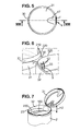
- a method of fixing a metering device 100 permitted with a package 1 according to the invention will now be described in connection with the figures 1 and 6 to 9 .
- the cover 31 can be curved and has a significant height (for example between 2 and 5 cm).
- the cover 31 thus has a side wall 220 which facilitates its handling and a top wall P to cover the opening 24.
- One or more objects, in particular a metering utensil 100 when the package contains milk powder, can then stored in the interior volume defined by the lid 31.
- the lid 31 is hinged to the frame 32 and the interior volume for the storage of the measuring utensil 100 is located between the opening 24 of the container and the upper wall P of the cover 31 for the closed position.
- the metering device 100 can be packaged in a bag and placed between the lid and the lid 31 in the package 1 ready for sale.
- the metering utensil 100 has a bucket 15 connected to a handle 16.
- the dimensions, in particular the length, of the utensil make it possible to arrange the latter in the plane of the frame 32.
- a single hooking zone is provided on the radially inner side wall of the frame 32 to hold the measuring utensil 100 in the upper part of the packaging by the bucket 15. 1.
- the frame 32 can here correspond both to a portion of the container 2 to an element attached to the container 2, as can be appreciated by those skilled in the art.
- the inner side wall has at least one retaining member which has a base b extending from the frame 32 towards the central axis Z of the container 2 and is extended by a tongue 5 extending upwardly away from the inner wall of the frame 32.
- the retaining member delimits with this inner side wall an insertion housing L adapted to receive with a small clearance a wall portion of the bucket 15 of the measuring utensil 100.
- the tongue 5 may be ribbed for a gain in rigidity, for example by means of two parallel ribs 55 projecting towards the central axis Z.
- the retaining member The function performed by the retaining member is to wedge the bucket wall portion inserted in the housing L.
- the tongue 5 may have a generally rectangular profile or more generally adapted to the wall shape of the bucket 15 of the housing. metering device. At least a portion of the tongue 5 may be parallel to the central axis Z.
- the tongue 5 may comprise at least one free end in contact with the wall portion of the bucket 15 inserted in the housing L.
- the tongue 5 of the retaining member comprises an upper free end arranged, for the closed position of the cover 31, with a determined spacing relative to the upper wall P in the closed position of the cover 31. This determined spacing is less than the depth of the bucket 15 to prevent the bucket portion 15 inserted in the insertion housing L out of this housing L, which would cause the metering utensil 100 to fall inside the container 2.
- the figure 7 illustrates the position of the metering device 100 to the frame 32 fixed by the retaining member.
- the handle 16 is disengaged with respect to the frame 32 and can be freely grasped by the user for use of the metering device 100.
- the retention of the bucket 15 can be carried out with an inverted position of the bucket with respect to the example of the figure 7 , with the bucket opening upwards.
- the tongue 5 can be inserted in a hollow defined at the bottom of the bucket. More generally, one or more tongues of the aforementioned type can be used to grip at least one wall portion of the bucket 15.
- the retaining member comprises at least three bearing zones each exerting a pressure on the wall portion of the bucket 15 to obtain a clamping of the bucket 15 of the metering device 100.
- Two of these zones each support is for example formed by a rib 52 of the inner frame side wall 32, emerging towards the central axis Z.
- the third bearing zone is provided by the side of the tongue 5 vis-à-vis the inner side wall of the frame 32.
- ribs 52 in contact with the outside of the wall portion of the bucket.
- These ribs 52 ensure for example both a clamping and guiding function.
- the thickness of the ribs 52 decreases towards the bottom of the housing L, which bottom is formed by the base b of the retaining member.
- This configuration of the ribs 52 produces an initial axis of insertion into the housing L of the bucket wall portion 15 which is slightly inclined with respect to the direction of the central axis Z, as can be seen in FIG. figure 9 .
- the tongue 5 extends in a global direction substantially parallel to the central axis Z.
- the single attachment zone is located on the hinge 30 side.
- the height of the frame 32 has a maximum H2 on the side of the retaining member, the height decreasing on either side of this maximum H2, preferably in a progressive manner, to reach a reduced height on the opposite side to this retaining member.
- the lid 31 may have a plane of symmetry corresponding to the section plane of the figure 1 .
- This plane of symmetry may include the central axis Z and crosses respectively median hinge 30, the depression 47 and the plate 41 of the locking device.
- the profile of the cover 31 is complementary to the profile of the frame 32.
- the maximum H2 height of the frame 32 is thus located on the side of the hinge 30, while the maximum H1 height the cover 31 is located opposite, that is to say on the side of the locking device 4 in the example shown.
- the lid 31 thus has a minimum height on the hinge side 30. This minimum is for example of the order of 1 or 2 cm and the maximum height H1 of the cover 31 is approximately double or triple compared to this minimum.
- the height of the metering device 100 in the fixing position on the retaining member (corresponding substantially to the depth of the bucket 15) is typically between 1 and 3 cm.
- the metering device 100 can therefore be positioned under the cover 31 in the closed position while being housed inside the volume defined by the cover 31 and the frame 32.
- the cover 31 comprises an inner skirt 21 for defining with the outer side wall 220 of the cover 31 a continuous groove 60.
- This groove 60 can completely surround the inner skirt 21.
- the side wall 220 deviates radially from the central axis Z towards a free edge of the side wall 220.
- the inner skirt 21 is substantially cylindrical about the central axis Z for example.
- the inner skirt 21 and the side wall 220 preferentially share the same central axis Z in a coaxial configuration.
- the frame 32 has an upper face which defines a wide opening 24 through which the user can use with a suitable tool powdered milk or similar content.
- the upper face of the frame 32 has a projecting annular projection 320 inserted in the groove 60 for the closed position of the cover 31. This projection annular 320 of the frame 32 thus contributes to a centering of the lid 31 during closure.
- the projecting annular projection 320 advantageously extends in the extension of the inner face of the side wall of the frame 32.
- the inside of the frame has a continuous appearance and preferably without a flange.
- the retaining member for the bucket 15 of the measuring utensil 100 is situated at a level lower than the annular projection 320. With the exception of this retaining member, the entire inner side wall of the frame 32 located above the lid is smooth. At the point where the junction with the lid 31 is thus removed, any surface such as an interior rim where the milk powder could be deposited is removed. Practically, closing the lid 31 thus arranged can be done without any discomfort.
- the annular projection 320 fits into the groove 60 without however joining the bottom of this groove 60.
- the height of the annular projection 320 is for example between 1 and 4 mm. It should be noted that the annular projection 320 extends mainly below a plane orthogonal to the central axis Z and passing through the axis of articulation of the hinge 30. On the figures 1 , 4 and 7 , it is visible that only part of the annular projection 320 near the hinge 30 exceeds above this plane (horizontal in the example of the figure 1 ) passing through the hinge 30.
- the inner skirt 21 preferentially covers an upper band of the inner side face of the frame 32 in this closed position and can thus fit through its entire periphery against the inside of the frame 32.
- the end free 210 of the inner skirt 21 is rounded or beveled to make more progressive the contact of the inner skirt 21 against the inner side wall of the frame 32 during the lowering of the lid 31.
- the inner skirt 21 may have, on the side close to the hinge 30 and on its inner face, one or more projecting contact surfaces for exerting, when closing the lid 31, a bearing on the cup 15 received in the body of the detention.
- This support makes it possible to drive the bucket wall portion inserted in the housing L in the direction of the base b.
- the protruding surface can be beveled to achieve this effect of driving the bucket 15 of the metering device 100 into the housing L.
- the effect produced by the projecting surface could, alternatively or additionally, lead to a beginning of lifting of the bucket during the operation of opening the lid 31.
- the hinge 30 it should be noted as illustrated in particular in the figure 7 that the depression 47 locally narrows the tubular volume defined by the inner skirt 21.
- the frame 32 has an outer peripheral face with respect to which the annular projection 320 is shifted inwards.
- the outer edge of the frame 32 adjacent to the annular projection 320 is covered by the edge of the side wall 220 as visible on the figure 8 .
- This edge-to-edge connection makes it possible to maintain a smooth outer profile for the frame-cover assembly, the outer skirt formed by the side wall 220 joining and extending the outer face of the frame 32 for the closed position.
- the side wall 220 and the inner skirt 21 meet and form in vertical section the branches of a Y, as illustrated in Figures 8 and 9 .
- the side wall 220 of the cover 31 is preferably in radial contact with the annular projection 320 for the closed position of the cover 31.
- the profile of the junction between the cover 31 and the frame 32 is curved and generally oblique, with the maximum height H1 of the cover 31 opposite the hinge 30.
- the profile of the wall Lateral 220 of the cover 31 has a gradually decreasing height towards the hinge 30.
- the frame 32 has a side wall whose height decreases progressively to the area where the engagement edge 33 is located.
- the annular projection 320 has a preferentially constant height and therefore has the same oblique profile as the side wall of the frame 32.
- the oblique profile of the junction from the hinge 30 and the rounded or beveled shape at the free end of the skirt internal 21 make the engagement of the inner skirt 21 with the inner side wall of the frame 32 more progressive when closing the lid 31. Therefore, the effort exerted by the user is more continuous, which increases the comfort of 'use. Indeed, it avoids a sudden engagement of the cover 31 on the frame 32 which generates a hard point of contact.
- the inner skirt 21 may extend below the edge-to-edge joining level between the cover 31 and the frame 32 for the closed position.
- the cover 31 may comprise radial ribs protruding from the inner skirt 21 towards the inside of the cover 31 to stiffen the latter. These ribs have for example a triangular profile and join the upper wall P of the cover 31.
- closure system 3 has been described in two parts with a cover 31 articulated or more generally removable relative to a frame 32 which is mounted on the container 2, it is clear that the cover 31 can seal the opening 24 by direct mounting on a container 2 of corresponding shape, with or without articulation by a hinge.
Abstract
Description
La présente invention se rapporte à un emballage avec couvercle de fermeture refermable destiné à un produit alimentaire. Plus particulièrement, l'invention se rapporte à un emballage comprenant :
- un récipient s'étendant selon un axe central depuis une base jusqu'à une face supérieure présentant une ouverture délimitée par un cadre, le cadre présentant une face intérieure ; et
- un système de fermeture comprenant un couvercle monté articulé par rapport au récipient entre une position d'ouverture et une position de fermeture pour laquelle il obture l'ouverture du récipient, le couvercle présentant une paroi supérieure.
- a container extending along a central axis from a base to an upper face having an opening defined by a frame, the frame having an inner face; and
- a closure system comprising a lid mounted hinged to the container between an open position and a closed position for which it closes the opening of the container, the lid having an upper wall.
Ce type d'emballage a un système de fermeture facile d'utilisation et est couramment employé dans le domaine alimentaire, par exemple pour contenir des produits alimentaires pulvérulents, granulaires ou floconneux. Le document
Il existe donc un besoin pour des emballages dotés d'un couvercle pratique et rapide à ouvrir et qui évitent l'accumulation de produit dans des parties supérieures de l'emballage.There is therefore a need for packaging with a convenient and quick-open lid that avoids accumulation of product in upper parts of the package.
L'invention a donc ici pour but de fournir un emballage refermable rendant facile la manipulation du couvercle et limitant au niveau de la fermeture les aspérités susceptibles de retenir la poudre ou les grains de petite taille contenus dans l'emballage.The purpose of the invention is therefore to provide a resealable package making easy the handling of the lid and limiting at the closure the asperities likely to retain the powder or small grains contained in the package.
A cet effet, l'emballage du type précité avec un couvercle à paroi supérieure est caractérisé en ce que le couvercle présente une paroi latérale s'étendant depuis la paroi supérieure et une jupe intérieure s'étendant à partir de la paroi latérale et à distance de la paroi supérieure pour définir avec la paroi latérale une rainure continue, en ce que le cadre présente une face supérieure qui comporte une projection annulaire saillante s'étendant dans le prolongement de la face intérieure du cadre, et en ce que la jupe intérieure s'appuie au moins partiellement sur ladite face intérieure du cadre pour la position de fermeture.For this purpose, the packaging of the aforementioned type with a top wall cover is characterized in that the cover has a side wall extending from the top wall and an inner skirt extending from the side wall and at a distance of the upper wall to define with the side wall a continuous groove, in that the frame has an upper face which comprises a projecting annular projection extending in the extension of the inner face of the frame, and in that the inner skirt s is at least partially supported on said inner face of the frame for the closed position.
Ainsi, il est permis d'obtenir un emballage ergonomique et manipulable sans effort, que l'on peut utiliser pour contenir du lait en poudre sans accumulation de poudre sur des rebords supérieurs du cadre ou du récipient. En effet, la présence de la jupe intérieure limite, voire supprime, les aspérités dans le volume intérieur de l'emballage qui sont susceptibles de retenir la poudre. Si un contenu poudreux ou granuleux de l'emballage est projeté contre l'intérieur du couvercle fermé (par exemple suite à un retournement lors d'un transport), on ne retrouvera pas d'accumulation de poudre au-dessus du récipient lors de l'ouverture suivante de l'emballage.Thus, it is possible to obtain an ergonomic packaging and easy to handle, that can be used to contain powdered milk without accumulation of powder on the upper edges of the frame or container. Indeed, the presence of the inner skirt limits or even eliminates asperities in the interior volume of the package that are likely to retain the powder. If a powdery or granular content of the packaging is thrown against the inside of the closed lid (for example following a turnaround during transport), there will be no accumulation of powder above the container during next opening of the package.
De plus, l'insertion de la projection annulaire du cadre dans la rainure peut contribuer avantageusement à un centrage du couvercle lors de la fermeture. L'insertion dans cette rainure peut aussi procurer une amélioration de l'étanchéité. Egalement, le couvercle peut délimiter un volume intérieur relativement important grâce à la surélévation de la paroi supérieure par rapport à la rainure. Ce gain de volume sous le couvercle est avantageusement obtenu avec une portion de paroi latérale s'étendant au-dessus de la rainure, ce qui permet de limiter les dimensions de la rainure et réaliser ainsi une économie de matière pour l'emballage.In addition, the insertion of the annular projection frame in the groove can advantageously contribute to a centering of the lid during closure. Insertion into this groove can also provide improved sealing. Also, the cover may delimit a relatively large interior volume by raising the upper wall relative to the groove. This volume gain under the cover is advantageously obtained with a side wall portion extending above the groove, which limits the size of the groove and thus save material for packaging.
Selon une autre particularité, le cadre est rapporté sur le récipient et le système de fermeture comprend une charnière reliant de manière articulée le cadre au couvercle, ledit cadre présentant un profil de hauteur progressivement décroissante en s'éloignant de la charnière.According to another feature, the frame is attached to the container and the closure system comprises a hinge connecting the hinged frame to the cover, said frame having a gradually decreasing height profile away from the hinge.
Selon une autre particularité, la paroi latérale et la jupe intérieure se rejoignent pour former, en section verticale, les branches d'un Y. Ceci limite la quantité de matière plastique nécessaire à la fabrication du couvercle.According to another feature, the side wall and the inner skirt meet to form, in vertical section, the branches of a Y. This limits the amount of plastic material required for the manufacture of the lid.
Selon une autre particularité, la jupe intérieure s'étend au-delà de la paroi latérale. Ainsi, la fermeture est facilitée, notamment lorsque le couvercle présente une certaine flexibilité et a une moindre hauteur à l'opposé de la charnière, grâce à l'effet de guidage/centrage provoqué par cette jupe intérieure.In another feature, the inner skirt extends beyond the side wall. Thus, the closure is facilitated, especially when the cover has a certain flexibility and has a lower height opposite the hinge, thanks to the guiding / centering effect caused by this inner skirt.
Selon une autre particularité, le cadre présente une face extérieure périphérique par rapport à laquelle la projection annulaire est décalée vers l'intérieur, la paroi latérale du couvercle s'étendant dans le prolongement de ladite face extérieure du cadre pour la position de fermeture. Ainsi le couvercle apporte un surplus de volumeAccording to another feature, the frame has a peripheral outer face with respect to which the annular projection is shifted inwards, the side wall of the lid extending in the extension of said outer face of the frame for the closed position. So the lid brings a surplus of volume
(notamment en hauteur) par rapport au cadre, ce qui peut permettre de loger un ou plusieurs objets dans le volume défini par le couvercle.(especially in height) relative to the frame, which can accommodate one or more objects in the volume defined by the lid.
Selon une autre particularité, la projection annulaire a une hauteur sensiblement constante et est disposée obliquement par rapport à la face supérieure du récipient.According to another feature, the annular projection has a substantially constant height and is arranged obliquely with respect to the upper face of the container.
Selon une autre particularité, la jupe intérieure présente une extrémité libre biseautée sur son côté extérieur et s'ajuste par l'ensemble de sa périphérie contre l'intérieur du cadre. Ceci a pour effet de rendre plus progressif et moins dur le contact radial de la jupe intérieure contre la face intérieur du cadre.According to another feature, the inner skirt has a free end beveled on its outer side and is adjusted by all of its periphery against the inside of the frame. This has the effect of making more progressive and less hard the radial contact of the inner skirt against the inner face of the frame.
Selon une autre particularité, l'emballage comprend un ustensile doseur à godet, le cadre comprenant, de préférence du côté de la charnière, un organe de retenue à languette délimitant avec la face intérieure du cadre un logement ouvert vers le haut et destiné à la réception d'une portion de paroi du godet de l'ustensile doseur, la jupe intérieure s'étendant, dans la position de fermeture du couvercle, jusqu'à proximité dudit logement pour coopérer avec le godet reçu dans le logement. Ceci permet par exemple d'enfoncer un peu plus le godet dans le logement lorsque l'on ferme le couvercle, ou encore de désengager en partie le godet du logement lors de l'ouverture, mais aussi d'exercer une force d'appui sur le godet reçu dans le logement.According to another particularity, the packaging comprises a metering device with a cup, the frame comprising, preferably on the hinge side, a tab retaining member delimiting with the inner face of the frame an upwardly open housing intended for the receiving a wall portion of the bucket of the measuring utensil, the inner skirt extending, in the closed position of the lid, to near said housing to cooperate with the bucket received in the housing. This allows for example to push a little more bucket in the housing when closing the lid, or to partially disengage the bucket housing when opening, but also to exert a force on the bucket received in the housing.
Selon une autre particularité, le couvercle comprend des nervures radiales saillantes depuis la jupe intérieure vers l'intérieur du couvercle, et rejoignant la paroi supérieure du couvercle. Les nervures radiales vers l'axe central permettent de rigidifier la jupe et favorisent le centrage lors de la fermeture.According to another feature, the cover comprises radial ribs protruding from the inner skirt towards the inside of the lid, and joining the upper wall of the lid. The radial ribs towards the central axis stiffen the skirt and promote centering during closure.
Selon une autre particularité, le cadre présente un bord extérieur adjacent à la projection annulaire, le bord extérieur du cadre étant en contact, dans la position de fermeture du couvercle, avec le bord libre de la paroi latérale, le bord libre de la paroi latérale ayant une largeur identique à la largeur dudit bord extérieur.According to another feature, the frame has an outer edge adjacent to the annular projection, the outer edge of the frame being in contact, in the closed position of the lid, with the free edge of the side wall, the free edge of the side wall. having a width identical to the width of said outer edge.
L'invention se rapporte également à un système de fermeture pour emballage comprenant :
- un cadre annulaire délimitant une ouverture, le cadre présentant une face intérieure ;
- un couvercle articulé sur le cadre et mobile entre une position d'ouverture et une position de fermeture pour laquelle il obture l'ouverture par le dessus, le couvercle présentant une paroi supérieure ;
- an annular frame defining an opening, the frame having an inner face;
- a cover hinged to the frame and movable between an open position and a closed position for which it closes the opening from above, the cover having an upper wall;
Indépendamment ou en combinaison avec ce qui précède, étant entendu que chacun des exemples et des détails de réalisation qui vont être décrits par la suite peuvent être utilisés isolément, l'invention se rapporte ici à un système de fermeture et à un emballage destiné notamment aux produits alimentaires, cet emballage comprenant :
- un récipient s'étendant selon un axe central depuis une base jusqu'à une face supérieure présentant une ouverture délimitée par un cadre, le cadre présentant une paroi latérale radialement intérieure ;
- un couvercle mobile entre une position d'ouverture et une position de fermeture pour laquelle il obture l'ouverture ;
- un ustensile doseur présentant un godet relié à un manche, dimensionné pour être agencé dans le plan du cadre.
- a container extending along a central axis from a base to an upper face having an opening defined by a frame, the frame having a radially inner side wall;
- a cover movable between an open position and a closed position for which it closes the opening;
- a measuring utensil having a bucket connected to a handle, dimensioned to be arranged in the plane of the frame.
Il est connu, par le document
Il est également connu, par le document
Il existe donc un besoin pour des emballages alimentaires permettant de ranger un ustensile doseur à l'intérieur et limitant les contacts susceptibles de contaminer l'aliment, tout en étant pratique à manipuler pour l'utilisateur.There is therefore a need for food packaging for storing a metering utensil inside and limiting the contacts likely to contaminate the food, while being convenient to handle for the user.
La présente invention a donc pour but de pallier un ou plusieurs des inconvénients susmentionnés en fournissant un emballage refermable avec un rangement intérieur d'un ustensile doseur qui diminue les occasions de souillure, et répond également aux contraintes d'encombrement et d'ordre pratique.The present invention therefore aims to overcome one or more of the aforementioned disadvantages by providing a resealable package with an inner storage of a metering device that reduces the opportunities for soil, and also meets the constraints of space and convenience.
A cet effet, l'emballage du type précité comprenant un ustensile doseur à godet est caractérisé en ce que la paroi latérale intérieure du cadre comporte au moins un organe de retenue qui présente une base s'étendant depuis le cadre vers l'axe central du récipient et prolongée par une languette s'étendant vers le haut à distance de ladite paroi latérale intérieure, l'organe de retenue délimitant avec la paroi latérale intérieure un logement d'insertion apte à recevoir avec un faible jeu une portion de paroi du godet de l'ustensile doseur, l'ustensile doseur étant maintenu dans une position de rangement intérieur le long du couvercle par l'organe de retenue pour ladite position de fermeture.For this purpose, the packaging of the above-mentioned type comprising a metering device with a cup is characterized in that the inner side wall of the frame comprises at least one retaining member which has a base extending from the frame towards the central axis of the container. container and extended by a tongue extending upwardly away from said inner side wall, the retaining member delimiting with the inner side wall an insertion housing adapted to receive with a small clearance a wall portion of the bucket of the metering utensil, the metering utensil being held in an interior storage position along the lid by the retaining member for said closed position.
Ainsi, il est permis avec ces dispositions de loger l'ustensile doseur de façon rapide sous le couvercle avant sa fermeture, sans contact ni avec l'intérieur du couvercle ni avec le godet puisque le manche est directement accessible par son extrémité libre.Thus, it is permitted with these provisions to accommodate the metering device quickly under the lid before closing, without contact with the inside of the lid or with the bucket since the handle is directly accessible by its free end.
Selon une autre particularité, le couvercle comporte une paroi latérale de forme tubulaire et une paroi supérieure transversale, la languette de l'organe de retenue comprenant une extrémité libre supérieure disposée, pour la position de fermeture du couvercle, avec un écartement déterminé suivant la direction de l'axe central par rapport à la paroi supérieure du couvercle, l'écartement déterminé étant inférieur à la profondeur du godet.According to another particularity, the lid comprises a tubular-shaped lateral wall and a transverse upper wall, the tongue of the body of retainer comprising an upper free end arranged, for the closed position of the lid, with a determined spacing in the direction of the central axis relative to the upper wall of the lid, the determined spacing being less than the depth of the bucket.
Ainsi, l'ustensile doseur accroché à l'organe de retenue ne peut pas remonter dans l'emballage fermé et le godet reste solidaire du crochet. Il n'y a donc aucun risque de chute de l'ustensile doseur dans le récipient avec le produit alimentaire.Thus, the metering device attached to the retainer can not go back in the closed package and the bucket remains attached to the hook. There is therefore no risk of the metering device falling into the container with the food product.
Selon une autre particularité, le cadre a une hauteur présentant un maximum au niveau du côté de l'organe de retenue.According to another feature, the frame has a height having a maximum at the side of the retaining member.
Ainsi, le cadre peut avoir une hauteur moindre à distance de l'organe/support de retenue, ce qui facilite la dépose de l'ustensile doseur sur le crochet sans toucher les bords ou l'intérieur du cadre. La dépose et l'extraction de l'ustensile sont plus intuitives pour l'utilisateur.Thus, the frame may have a lower height away from the body / support retaining, which facilitates the removal of the measuring utensil on the hook without touching the edges or the inside of the frame. The removal and extraction of the utensil are more intuitive for the user.
Selon une autre particularité, la languette s'étend sur une hauteur représentant de 40 à 80% de dudit maximum de hauteur du cadre.According to another feature, the tongue extends over a height representing 40 to 80% of said maximum height of the frame.
Selon une autre particularité, le cadre présente un profil de hauteur progressivement décroissante en s'éloignant de l'organe de retenue. Ainsi, la saisie du manche du godet se fait avec un minimum de gêne du cadre, qui a une hauteur moindre du côté du manche que celle du côté du godet.According to another feature, the frame has a gradually decreasing height profile away from the retaining member. Thus, the seizure of the handle of the bucket is done with a minimum of discomfort of the frame, which has a lower height of the side of the handle than that of the side of the bucket.
Selon une autre particularité, la hauteur du cadre varie environ d'un facteur 2:1 entre son maximum et son minimum.In another feature, the height of the frame varies about a factor of 2: 1 between its maximum and its minimum.
Selon une autre particularité, l'organe de retenue comprend au moins trois zones d'appui exerçant chacun une pression sur une portion de paroi du godet pour obtenir un serrage du godet. Ainsi, l'ustensile est calé de manière fiable par un seul côté.According to another particularity, the retaining member comprises at least three bearing zones each exerting pressure on a wall portion of the bucket to obtain a clamping of the bucket. Thus, the utensil is stalled reliably by one side.
Selon une autre particularité, deux des zones d'appui sont chacune formées par une nervure du cadre ressortant vers l'axe central. Les nervures peuvent avoir une forme triangulaire, avec le maximum d'épaisseur à proximité de l'entrée du logement d'insertion pour accroître l'appui quant le godet est complètement inséré dans le logement.According to another feature, two of the support zones are each formed by a rib of the frame emerging towards the central axis. The ribs may have a triangular shape, with the maximum thickness near the inlet of the insertion housing to increase support when the bucket is fully inserted into the housing.
Selon une autre particularité, le couvercle comporte une jupe intérieure tubulaire dont une partie s'étend, dans la position de fermeture du couvercle, jusqu'à proximité dudit logement. La jupe intérieure s'appuie radialement sur une partie supérieure de ladite paroi latérale intérieure du cadre et peut contribuer par exemple au maintien du godet dans le logement.According to another feature, the lid has a tubular inner skirt, a portion of which extends, in the closed position of the lid, to near said housing. The inner skirt is supported radially on an upper portion of said inner side wall of the frame and may contribute for example to maintaining the bucket in the housing.
Pour la position de fermeture, le godet est donc recouvert par le couvercle à la fois par le haut et frontalement par la jupe intérieure.For the closed position, the bucket is covered by the cover both from above and frontally by the inner skirt.
Un objet de l'invention est également de fournir un système de fermeture permettant de ranger de façon pratique l'ustensile doseur au niveau du dispositif de fermeture.An object of the invention is also to provide a closure system for conveniently storing the measuring utensil at the closure device.
Pour cela, il est proposé un système de fermeture pour emballage, comprenant ;
- un cadre s'étendant selon une forme générale tubulaire autour d'un axe central et délimitant une ouverture, le cadre présentant une paroi latérale radialement intérieure ;
- un couvercle articulé sur le cadre et mobile entre une position d'ouverture et une position de fermeture pour laquelle il obture l'ouverture par le dessus ;
- un ustensile doseur présentant un godet relié à un manche, dimensionné pour être agencé dans le plan du cadre ;
- a frame extending in a generally tubular shape about a central axis and defining an opening, the frame having a radially inner side wall;
- a cover hinged to the frame and movable between an open position and a closed position for which it closes the opening from above;
- a measuring utensil having a bucket connected to a handle, dimensioned to be arranged in the plane of the frame;
Il est avantageusement permis grâce à ces dispositions, avec une prise de l'ustensile simplement au niveau du manche, de respectivement insérer le godet dans le logement d'insertion avant fermeture du couvercle ou d'extraire le godet de l'organe de retenue après ouverture du couvercle. On comprend que ce système de fermeture, qui résout un problème de rangement d'un ustensile doseur, est utilisable indépendamment du système de verrouillage retenu et/ou indépendamment de la présence d'une jupe intérieure avec le couvercle.It is advantageously allowed thanks to these provisions, with a catch of the utensil simply at the handle, respectively to insert the bucket in the insertion housing before closing the lid or to extract the cup from the retainer after opening the lid. It is understood that this closure system, which solves a storage problem of a measuring utensil, is used independently of the locking system and / or regardless of the presence of an inner skirt with the lid.
D'autres caractéristiques et avantages de l'invention ressortiront de la description qui va suivre, donnée à titre d'exemple non limitatif, en référence aux figures dans lesquelles :
- la
figure 1 est une vue en coupe d'un emballage selon l'invention comprenant un dispositif de verrouillage et un couvercle en position d'ouverture, ainsi qu'un ustensile doseur associé ; - les
figures 2A et 2B représentent chacune selon le plan de coupe VIII-VIII de lafigure 5 le dispositif de verrouillage avec les deux parties de ce dispositif respectivement avant et après verrouillage ;
- les
figures 3A et 3B représentent deux vues en perspective de la partie du dispositif de verrouillage lié au couvercle ; - la
figure 4 est une vue en perspective de l'emballage de lafigure 1 ; - la
figure 5 est une vue de dessus du couvercle ; - la
figure 6 est une vue en perspective détaillant la zone de jonction du couvercle et du cadre ; - la
figure 7 est une vue en perspective illustrant l'accrochage de l'ustensile doseur dans l'emballage ; - la
figure 8 est une vue en coupe selon le plan VIII-VIII du système de fermeture en position de fermeture ; et - la
figure 9 est une vue, selon le même plan de coupe que pour lafigure 1 , illustrant plus en détail les formes complémentaires du cadre et du couvercle.
- the
figure 1 is a sectional view of a package according to the invention comprising a locking device and a lid in the open position, and an associated metering device; - the
Figures 2A and 2B each represent according to the sectional plan VIII-VIII of thefigure 5 the locking device with the two parts of this device respectively before and after locking;
- the
Figures 3A and 3B represent two perspective views of the part of the locking device connected to the lid; - the
figure 4 is a perspective view of the packaging of thefigure 1 ; - the
figure 5 is a top view of the lid; - the
figure 6 is a perspective view detailing the junction area of the cover and the frame; - the
figure 7 is a perspective view illustrating the attachment of the metering device in the package; - the
figure 8 is a sectional view along the plane VIII-VIII of the closure system in the closed position; and - the
figure 9 is a view, according to the same sectional plan as for thefigure 1 , illustrating in more detail the complementary shapes of the frame and the lid.
Sur les différentes figures, des références identiques indiquent des éléments identiques ou similaires.In the various figures, identical references indicate identical or similar elements.
En référence à la
Le récipient 2 possède dans le mode de réalisation représenté une paroi latérale tubulaire 22 qui s'étend à partir de la base 20 selon un axe central vertical Z jusqu'à une face supérieure 23. Dans l'exemple des
Dans le cas d'utilisation de l'emballage 1 pour contenir de la poudre de lait, on prévoit un opercule, non représenté, qui est scellé de manière étanche par exemple sur une bordure intérieure ou sur le pourtour 25 du récipient 2. Ainsi, la poudre de lait est parfaitement préservée dans le récipient 2 jusqu'à la première utilisation, lors de laquelle l'opercule est arraché.In the case of using the package 1 to contain milk powder, there is provided a lid, not shown, which is sealingly sealed for example on an inner edge or around the
En référence aux
Le système de fermeture 3 comporte de plus un cadre 32 qui délimite l'ouverture 24. Dans un mode de réalisation préféré, le cadre 32 peut être monté de manière ajustée sur une partie supérieure ou col du récipient 2. Le cadre 32 est fixé de préférence de manière inamovible à cette partie du récipient 2, notamment par encliquetage, mais cette fixation pourrait être également assurée par collage ou soudage. Dans l'exemple non limitatif des
L'ouverture 24 peut être légèrement rétrécie par rapport à la section du récipient, par exemple en raison de la présence d'un bord d'arasage. Dans ce cas, le cadre 32 peut délimiter une ouverture de dimensions différentes et préférentiellement supérieures à celle de l'ouverture rétrécie.The
En référence aux
La liaison est ici une liaison charnière 30 dont l'axe de pivotement est perpendiculaire à l'axe central Z. Dans le mode de réalisation représenté, il s'agit d'une charnière 30 en plastique formée par une ligne de pliage, qui permet de réaliser le couvercle 31 et le cadre 32 en une seule pièce. Il s'agit d'une pièce obtenue par injection dans un moule d'une matière plastique, comme par exemple du polypropylène. Mais, bien entendu, la liaison charnière 30 peut être obtenue par deux pièces distinctes assemblées, et il est également possible de prévoir un autre type de liaison entre le cadre 32 et le couvercle 31. Dans des variantes où le cadre fait partie du récipient 2, on comprend que le couvercle 31 peut alors être monté amovible sur la partie supérieure ou col du récipient 2.The link is here a
Comme cela est visible aux
En exerçant une pression avec le doigt ou le pouce sur une zone préférentiellement centrale de la portion d'actionnement 410, comme indiquée par la flèche A à la
En référence aux
La dépression 47 est définie par une portion en creux de la paroi supérieure P du couvercle 31 présentant un débouché radialement extérieur qui est délimité par la rupture de géométrie avec le profil extérieur de l'ensemble du couvercle 31. Il est à noter que la portion d'actionnement 410 de la plaquette de verrouillage 41 est située au niveau du débouché de la dépression 47. La dépression 47 a préférentiellement une profondeur croissante en direction du débouché de la dépression 47, comme cela est visible sur les
Plus généralement, la forme de la dépression 47 est choisie de manière à ce que son débouché soit suffisamment large pour que l'utilisateur puisse tenir facilement entre deux doigts la zone d'actionnement de la plaquette de verrouillage 41. La plaquette de verrouillage 41 peut alors pivoter dans la dépression 47 pour prendre la position de déverrouillage. La plaquette de verrouillage possède un débattement important grâce à la dépression 47 du couvercle 31. A titre d'exemple non limitatif, l'extrémité libre 42 de la portion d'actionnement 410 peut être au moins trois fois plus éloignée de l'axe 400 de pivotement que ne l'est l'extrémité libre 43 de la portion d'accrochage 420. La plaquette 41 peut donc réagir comme un levier, avec un retour de levier par défaut dans la position de prise facilite le verrouillage.More generally, the shape of the
Comme illustré à la
En référence aux
Dans le mode de réalisation représenté, le rebord de prise 33 est constitué par une portion du cadre 32 située en regard de la patte de verrouillage 41, et plus précisément positionnée sur la périphérie extérieure de la face supérieure du cadre 32.In the embodiment shown, the
Il est à noter que la section transversale de la plaquette de verrouillage 41 n'est pas nécessairement un rectangle parfait. La face radialement intérieure de la plaquette de verrouillage 41 peut présenter une ou plusieurs nervures pour ajuster sa rigidité, et donc la force nécessaire pour éloigner l'extrémité libre 43 du rebord de prise 33. Comme illustré dans les
En référence à la
La portion d'accrochage 420 peut comporter un ou plusieurs ergots 430 orientés radialement vers l'intérieur par rapport à l'axe central Z et venant en prise avec le rebord de prise 33 par le dessous pour la position de verrouillage. Chaque ergot 430 présente globalement la forme d'une nervure saillante s'étendant horizontalement en travers de la face intérieure de la plaquette de verrouillage 41 avec un profil trapézoïdal, en quart de rond ou sensiblement triangulaire. A titre d'exemple, deux ergots 430 espacés peuvent s'étendre ainsi avec une épaisseur croissante depuis l'extrémité libre 43 de la portion d'accrochage 420 jusqu'à un niveau sensiblement horizontal adjacent à l'axe 400 de pivotement de la plaquette de verrouillage 41.The hooking
Un encliquetage est ainsi obtenu grâce aux ergots 430 de la portion d'accrochage 420. Néanmoins, pour obtenir un tel encliquetage, il n'est pas absolument nécessaire que les ergots 430 ou la portion d'accrochage 420 ait nécessairement un tel profil. En effet, au moins un ergot 430 pourrait avoir un profil différent, par exemple la forme d'un bourrelet, notamment avec un profil du rebord de prise 33 sensiblement différent d'un rectangle.A snap is thus obtained thanks to the
Le couvercle 31 ne peut alors plus pivoter autour de l'axe défini par la charnière 30 disposée à l'opposé du dispositif de verrouillage 4 ni être soulevé par un mouvement de translation. Autrement dit, on comprend ainsi qu'il est possible dans la position de verrouillage de porter l'emballage 1 par la zone de préhension de la plaquette de verrouillage 41 sans déclencher l'ouverture du couvercle 31, dès lors que la portion d'actionnement 410 n'est pas pivotée vers la dépression 47 du couvercle 31.The
Le dispositif de verrouillage 4 a pour but d'éviter une sortie involontaire du produit après une première ouverture lorsque l'opercule a été arraché, mais n'a pas pour but de réaliser une fermeture étanche telle qu'elle a été obtenue préalablement avec l'opercule.The purpose of the
Dans le mode de réalisation des
Dans le mode de réalisation des
Chacun des témoins 6 d'effraction, préférentiellement au nombre de deux, est agencé au niveau du débouché de la dépression 47 et chaque dent qui constitue le témoin 6 est conformée pour s'étendre dans le prolongement du profil extérieur de l'ensemble du couvercle 31. Ceci confère à l'emballage 1 un aspect particulièrement esthétique et limite les possibilités d'accrochage avec tout objet au cours de son cycle d'utilisation. De plus, le fait de rendre les témoins 6 d'effraction solidaires du couvercle 31 évite une chute éventuelle de ces témoins 6 à l'intérieur du récipient 2. Dans l'exemple des
Il a été mentionné ici un pontet sécable par témoin 6 d'effraction mais, bien entendu, le nombre de pontets et leur disposition pourrait être sensiblement différente. Par exemple, un témoin 6 d'effraction pourrait recouvrir partiellement la surface avant ou arrière de la plaquette de verrouillage 41.It has been mentioned here a breakable
Le cycle d'utilisation de l'emballage 1 peut se dérouler de la manière suivante. Après moulage par injection de l'ensemble du dispositif de fermeture 3 avec les dispositifs de verrouillage et d'inviolabilité (4, 6), on obtient une seule pièce qui peut être configurée en position de fermeture avec le couvercle 31 rabattu sur le cadre 32. Grâce aux dispositifs de verrouillage 4 et d'inviolabilité, cette configuration est conservée.The cycle of use of the package 1 can be carried out as follows. After injection molding of the
Le dispositif de fermeture 3 ainsi constitué peut alors être aisément monté sur le récipient 2 préalablement rempli et operculé, par exemple par encliquetage. L'emballage 1 est alors prêt à la vente. Toute tentative d'ouverture manuelle entraînera une rupture d'au moins une des liaisons frangibles, et sera donc généralement aisément détectable par le consommateur.The
Lors de la première utilisation, l'utilisateur rompra par pivotement de la plaquette 41 les liaisons frangibles des témoins 6 d'effraction. Le fait de déverrouiller ainsi le dispositif de verrouillage 4 permet de déplacer le couvercle 31. Par une pression exercée sur la zone extérieure, visible à la
En refermant l'emballage 1, c'est-à-dire en rabattant le couvercle 31, le verrouillage est assuré automatiquement par l'encliquetage de la portion d'accrochage 420 avec le rebord de prise 33. Ensuite, pour une nouvelle utilisation, il suffit d'exercer à nouveau une pression sur la zone centrale de la portion d'actionnement 410 pour libérer le dispositif de verrouillage 4.By closing the package 1, that is to say by folding the
Un mode de fixation d'un ustensile doseur 100 permis avec un emballage 1 conforme à l'invention va à présent être décrit en liaison avec les
En référence à la
Initialement, l'ustensile doseur 100 peut être conditionné dans un sachet et placé entre l'opercule et le couvercle 31 dans l'emballage 1 prêt à la vente. L'ustensile doseur 100 présente un godet 15 relié à un manche 16. Les dimensions, en particulier la longueur, de l'ustensile, permettent d'agencer ce dernier dans le plan du cadre 32. Pour un récipient 2 de type circulaire, on comprend que la longueur de l'ustensile doseur 100 reste inférieure au diamètre intérieur du cadre 32.Initially, the
Pour ne pas engendrer de contacts susceptibles de souiller l'aliment, il est prévu sur la paroi latérale radialement intérieure du cadre 32 une unique zone d'accrochage pour retenir par le godet 15 l'ustensile doseur 100 dans la partie supérieure de l'emballage 1. Le cadre 32 peut ici correspondre aussi bien à une partie du récipient 2 qu'à un élément rapporté sur le récipient 2, comme peut l'apprécier l'homme du métier. Comme illustré à la
La fonction réalisée par l'organe de retenue est de caler la portion de paroi de godet insérée dans le logement L. Pour cela, la languette 5 peut avoir un profil globalement rectangulaire ou plus généralement adapté à la forme de paroi du godet 15 de l'ustensile doseur. Au moins une portion de la languette 5 peut être parallèle à l'axe central Z. La languette 5 peut comporter au moins une extrémité libre en contact avec la portion de paroi du godet 15 inséré dans le logement L.The function performed by the retaining member is to wedge the bucket wall portion inserted in the housing L. For this, the
En référence à la
Dans un mode de réalisation préféré, l'organe de retenue comprend au moins trois zones d'appui exerçant chacune une pression sur la portion de paroi du godet 15 pour obtenir un serrage du godet 15 de l'ustensile doseur 100. Deux de ces zones d'appui sont par exemple chacune formées par une nervure 52 de la paroi latérale intérieure cadre 32, ressortant vers l'axe central Z. La troisième zone d'appui est fournie par le côté de la languette 5 en vis-à-vis de la paroi latérale intérieure du cadre 32.In a preferred embodiment, the retaining member comprises at least three bearing zones each exerting a pressure on the wall portion of the
En référence aux
Dans le mode de réalisation avec une charnière élastique 30 qui relie le couvercle 31 au cadre 32, l'unique zone d'accrochage est située du côté de la charnière 30. Comme illustré notamment à la
En référence aux
Un agencement du couvercle 31 adapté pour un emballage alimentaire conforme à l'invention et destiné à de la poudre de lait va à présent être plus particulièrement décrit en liaison avec les
Comme cela est visible dans les
En référence aux
La projection annulaire saillante 320 s'étend avantageusement dans le prolongement de la face intérieure de la paroi latérale du cadre 32. Ainsi, l'intérieur du cadre à un aspect continu et préférentiellement dépourvue de rebord. Dans le mode de réalisation représenté, l'organe de retenue pour le godet 15 de l'ustensile doseur 100 est situé à un niveau plus bas que la projection annulaire 320. Si l'on excepte cet organe de retenue, l'ensemble de la paroi latérale intérieure du cadre 32 située au dessus de l'opercule est lisse. On supprime ainsi à l'endroit de la jonction avec le couvercle 31 toute surface telle qu'un rebord intérieur où pourrait se déposer la poudre de lait. Pratiquement, la fermeture du couvercle 31 ainsi agencé peut s'effectuer sans aucune gêne.The projecting
En référence à la
La jupe intérieure 21 recouvre de façon préférentiellement continue une bande supérieure de la face latérale intérieure du cadre 32 dans cette position de fermeture et peut s'ajuster ainsi par l'ensemble de sa périphérie contre l'intérieur du cadre 32. L'extrémité libre 210 de la jupe intérieure 21 est arrondie ou biseautée pour rendre plus progressif le contact de la jupe intérieure 21 contre la paroi latérale intérieure du cadre 32 lors de l'abaissement du couvercle 31.The
La jupe intérieure 21 peut présenter, du côté proche de la charnière 30 et sur sa face intérieure, une ou plusieurs surfaces saillantes de contact pour exercer, lors de la fermeture du couvercle 31, un appui sur le godet 15 reçu dans l'organe de retenue. Cet appui permet d'enfoncer la portion de paroi de godet insérée dans le logement L en direction de la base b. La surface saillante peut être biseautée pour obtenir cet effet d'enfoncement du godet 15 de l'ustensile doseur 100 dans le logement L. L'effet produit par la surface saillante pourrait, de façon alternative ou complémentaire, entraîner un début de soulèvement du godet lors de l'opération d'ouverture du couvercle 31. A l'opposé de la charnière 30, il est à noter comme illustré notamment à la
En référence à la
La paroi latérale 220 et la jupe intérieure 21 se rejoignent et forment en section verticale les branches d'un Y, comme illustré aux
En référence aux
Comme cela est visible sur les
Selon une forme de réalisation non représentée, le couvercle 31 peut comporter des nervures radiales saillantes depuis la jupe intérieure 21 vers l'intérieur du couvercle 31 pour rigidifier ce dernier. Ces nervures ont par exemple un profil triangulaire et rejoignent la paroi supérieure P du couvercle 31.According to an embodiment not shown, the
Bien entendu, le mode de réalisation décrit cidessus n'est nullement limitatif et de nombreuses variantes concernant la géométrie des pièces constituant les dispositifs de verrouillage et d'inviolabilité ou le dispositif de retenue du godet 15 peuvent être réalisés sans sortir de la portée de l'invention telle que revendiquée. En particulier, bien que le système de fermeture 3 ait été décrit en deux parties avec un couvercle 31 articulé ou plus généralement amovible par rapport à un cadre 32 qui se monte sur le récipient 2, il est clair que le couvercle 31 peut obturer l'ouverture 24 par montage direct sur un récipient 2 de forme correspondante, avec ou sans articulation par une charnière.Of course, the embodiment described above is in no way limiting and numerous variants concerning the geometry of the parts constituting the locking and tamper-proof devices or the
Claims (14)
emballage dans lequel la projection annulaire (320) saillante s'insère dans la rainure (60) et la jupe intérieure (21) s'appuie au moins partiellement sur ladite face intérieure du cadre (32) pour la position de fermeture du couvercle (31).
packaging in which the projecting annular projection (320) fits into the groove (60) and the inner skirt (21) bears at least partially on said inner face of the frame (32) for the lid closing position (31). ).
Applications Claiming Priority (4)
| Application Number | Priority Date | Filing Date | Title |
|---|---|---|---|
| FR0708878A FR2925467B1 (en) | 2007-12-19 | 2007-12-19 | FOOD PACKAGING WITH CLOSURE COVER |
| FR0708877A FR2925466B1 (en) | 2007-12-19 | 2007-12-19 | REFERMABLE PACKAGE WITH CLOSURE SYSTEM LATCHING DEVICE |
| FR0708879A FR2925468B1 (en) | 2007-12-19 | 2007-12-19 | PACKAGING WITH A DEVICE FOR ATTACHING A DOSER USTENSIBLE |
| EP08864632A EP2227421B1 (en) | 2007-12-19 | 2008-12-18 | Food packaging with lid and closing system for packaging |
Related Parent Applications (1)
| Application Number | Title | Priority Date | Filing Date |
|---|---|---|---|
| EP08864632.8 Division | 2008-12-18 |
Publications (2)
| Publication Number | Publication Date |
|---|---|
| EP2388206A1 true EP2388206A1 (en) | 2011-11-23 |
| EP2388206B1 EP2388206B1 (en) | 2013-01-09 |
Family
ID=40792921
Family Applications (3)
| Application Number | Title | Priority Date | Filing Date |
|---|---|---|---|
| EP11173466A Active EP2388206B1 (en) | 2007-12-19 | 2008-12-18 | Food packaging with cover and sealing system for a package |
| EP08864632A Not-in-force EP2227421B1 (en) | 2007-12-19 | 2008-12-18 | Food packaging with lid and closing system for packaging |
| EP11173317A Not-in-force EP2374727B9 (en) | 2007-12-19 | 2008-12-18 | Food packaging with cover and sealing system for a package |
Family Applications After (2)
| Application Number | Title | Priority Date | Filing Date |
|---|---|---|---|
| EP08864632A Not-in-force EP2227421B1 (en) | 2007-12-19 | 2008-12-18 | Food packaging with lid and closing system for packaging |
| EP11173317A Not-in-force EP2374727B9 (en) | 2007-12-19 | 2008-12-18 | Food packaging with cover and sealing system for a package |
Country Status (9)
| Country | Link |
|---|---|
| US (3) | US20100264156A1 (en) |
| EP (3) | EP2388206B1 (en) |
| CN (3) | CN101939229A (en) |
| AT (1) | ATE519685T1 (en) |
| DK (1) | DK2374727T3 (en) |
| ES (2) | ES2396033T3 (en) |
| PL (1) | PL2374727T3 (en) |
| RU (2) | RU2633258C2 (en) |
| WO (1) | WO2009081050A2 (en) |
Cited By (1)
| Publication number | Priority date | Publication date | Assignee | Title |
|---|---|---|---|---|
| US8302805B2 (en) | 2008-08-26 | 2012-11-06 | Aptargroup, Inc. | Closure with utensil |
Families Citing this family (30)
| Publication number | Priority date | Publication date | Assignee | Title |
|---|---|---|---|---|
| US8511499B2 (en) | 2007-12-18 | 2013-08-20 | Abbott Laboratories | Container |
| RU2461506C2 (en) | 2006-12-27 | 2012-09-20 | Эбботт Лэборетриз | Container |
| US8469223B2 (en) | 2009-06-05 | 2013-06-25 | Abbott Laboratories | Strength container |
| MX340936B (en) | 2009-12-29 | 2016-08-01 | Nestec Sa | Dispensing apparatus having an overcap and scoop. |
| US8376179B2 (en) | 2010-06-28 | 2013-02-19 | Mead Johnson Nutrition Company | Container and closure |
| US8794458B2 (en) | 2010-06-28 | 2014-08-05 | Mead Johnson Nutrition Company | Container seal |
| US20110315686A1 (en) * | 2010-06-28 | 2011-12-29 | Mead Johnson Nutrition Company | Refillable Product Dispenser System |
| IT1403607B1 (en) * | 2010-12-22 | 2013-10-31 | Luigi Zaini S P A | CONTAINER OF SURPRISES PARTICULARLY FOR CHOCOLATE OBJECTS |
| MX2012007815A (en) * | 2011-07-01 | 2013-02-07 | Weatherchem Corp | Closure with stay open mechanism. |
| SG10201604661QA (en) * | 2012-04-27 | 2016-07-28 | Abbott Lab | A Container |
| US20140020341A1 (en) * | 2012-07-20 | 2014-01-23 | Patricia Coburn | Powder supplement scooping system and method |
| USD733320S1 (en) | 2013-04-26 | 2015-06-30 | Abbott Laboratories | Container |
| GB2514893B (en) * | 2013-06-04 | 2017-12-06 | Nicoventures Holdings Ltd | Container |
| FR3008395B1 (en) * | 2013-07-09 | 2016-04-15 | Ardagh Mp Group Netherlands Bv | PACKAGING STRUCTURE FOR STORING AND DISPENSING A BULK PRODUCT |
| CA2919304C (en) * | 2013-07-29 | 2018-01-16 | Danone | Two compartment plastic containers and food product pack comprising such containers |
| WO2015065818A1 (en) * | 2013-10-28 | 2015-05-07 | Choprix Llc | Container with attachable retrieval means |
| DE102013226962A1 (en) * | 2013-12-20 | 2015-06-25 | Henkel Ag & Co. Kgaa | closure device |
| MX2017001198A (en) * | 2014-08-07 | 2017-05-03 | Aptargroup Inc | Closure for a container and utensil therefor. |
| USD790343S1 (en) | 2015-01-14 | 2017-06-27 | Mead Johnson Nutrition Company | Closure |
| USD756778S1 (en) | 2015-01-14 | 2016-05-24 | Mead Johnson Nutrition Company | Closure |
| US9580219B2 (en) * | 2015-06-30 | 2017-02-28 | Anchor Packaging | Tamper evident plastic food container |
| NL2015661B1 (en) | 2015-10-26 | 2017-05-23 | Ipn Ip Bv | A product package and production method. |
| US20180354699A1 (en) * | 2015-12-04 | 2018-12-13 | Plastek Industries, Inc. | Scoop Dock and Assembly Methods |
| WO2018077392A1 (en) * | 2016-10-25 | 2018-05-03 | N.V. Nutricia | Container, seal with blister element, and scoop therefor |
| EP3727082B1 (en) * | 2017-12-19 | 2022-01-26 | GEKA GmbH | Cosmetic receptacle system for producing cosmetic receptacles while using identical parts |
| US20210130048A1 (en) * | 2018-04-09 | 2021-05-06 | Abbott Laboratories | Powder container with first and second hinged closures |
| US10954037B1 (en) * | 2018-09-14 | 2021-03-23 | Antonio Valdes Ibarra | Container with internally incorporated hook assembly |
| FR3093709B1 (en) * | 2019-03-13 | 2021-08-27 | United Caps France | Cap for rigid container |
| IT201900007746A1 (en) * | 2019-05-31 | 2020-12-01 | Sacmi | Hinged cap for a container. |
| NL2023251B1 (en) * | 2019-06-03 | 2020-12-11 | Weener Plastics Group B V | Closure with bonded tamper evidence |
Citations (7)
| Publication number | Priority date | Publication date | Assignee | Title |
|---|---|---|---|---|
| FR2747107A1 (en) | 1996-04-04 | 1997-10-10 | Bois Jacques | Dispensing cap for instant coffee container |
| GB2318784A (en) * | 1996-10-30 | 1998-05-06 | Rexam Containers Ltd | Closure with integral dispensing device |
| DE20021262U1 (en) * | 2000-12-15 | 2001-04-05 | Jokey Plastik Wipperfuerth | Container with snap-on lid |
| EP1157936A2 (en) * | 2000-05-26 | 2001-11-28 | Kraft Foods Holdings, Inc. | Food product container with closure |
| EP1512637A1 (en) | 2003-08-29 | 2005-03-09 | Huhtamaki France S.A. | Closure lid for food containers |
| WO2005075314A2 (en) | 2004-02-05 | 2005-08-18 | N.V. Nutricia | Packaging for pulverulent material |
| WO2007010174A1 (en) * | 2005-07-21 | 2007-01-25 | Reckitt Benckiser Healthcare (Uk) Limited | Packaging with sealing lid and method for filling the package |
Family Cites Families (29)
| Publication number | Priority date | Publication date | Assignee | Title |
|---|---|---|---|---|
| US1237504A (en) * | 1916-06-08 | 1917-08-21 | Caroline Graham | Spoon-holder. |
| US2738900A (en) * | 1954-02-24 | 1956-03-20 | Wenger Harry | Canister with scoop fastening means |
| US4095716A (en) * | 1977-04-28 | 1978-06-20 | Meany William T | Combined spoon and vessel |
| US4300008A (en) * | 1980-09-25 | 1981-11-10 | Standard Oil Company (Indiana) | Preparation of 2,6-dimethyldecalin and its isomers |
| US4346812A (en) * | 1981-03-10 | 1982-08-31 | The Continental Group, Inc. | Plastic closure with reinforced central panel |
| US4500008A (en) * | 1982-09-22 | 1985-02-19 | Pdl Industries Limited | Weatherproof and/or dust proof fitting |
| SE8804229L (en) * | 1988-11-23 | 1990-05-24 | Akerlund & Rausing Licens Ab | AEROUS CLOSING DEVICE FOR PLANT CUT OFF PACKAGING |
| US4986438A (en) * | 1990-04-03 | 1991-01-22 | Placon Corporation | Recloseable nesting tab container |
| US5193759A (en) * | 1990-12-28 | 1993-03-16 | Eastman Kodak Company | Film or paper cassette |
| US5322178A (en) * | 1993-04-21 | 1994-06-21 | Plastofilm Industries, Inc. | One-hand operable latch for tub type container |
| US5353946A (en) * | 1993-07-26 | 1994-10-11 | Church & Dwight Co., Inc. | Container with reclosable lid latch |
| FR2719558B1 (en) * | 1994-05-06 | 1996-06-21 | Astra Plastique | Tamper-evident cap for closing containers. |
| US5577626A (en) * | 1995-04-11 | 1996-11-26 | Aptargroup, Inc. | Closure with opening assist feature |
| US5706974A (en) * | 1995-12-20 | 1998-01-13 | Abbott Laboratories | Can for powder products having scoop retaining means |
| DE29613099U1 (en) * | 1996-07-29 | 1996-09-26 | Zajac Gerhard | Resealable jar for food |
| JPH10278962A (en) * | 1997-04-04 | 1998-10-20 | Ryoko Yamase | Attaching structure of content take-out utensil for packaging container |
| JPH10314027A (en) * | 1997-05-19 | 1998-12-02 | P-Kotsuku Mahobin Kogyo Kk | Lid fixing construction for vessel |
| DE29817273U1 (en) * | 1998-09-25 | 1998-12-24 | Liedtke Christian | Device for holding a spoon or fork-like removal device during breaks in use |
| US7243816B2 (en) * | 2003-02-13 | 2007-07-17 | Dart Industries Inc. | Container with one-piece seal and lid spring |
| US20040238553A1 (en) * | 2003-05-30 | 2004-12-02 | Lane Gordon S. | Container with hinged cover |
| JP4525127B2 (en) * | 2004-03-26 | 2010-08-18 | 凸版印刷株式会社 | 1 piece plug for aseptic filling and packaging |
| US7673769B2 (en) * | 2004-12-03 | 2010-03-09 | Rubbermaid Incorporated | Storage bin with moveable lid and attached scoop |
| US8042704B2 (en) * | 2005-01-19 | 2011-10-25 | Plastipak Packaging, Inc. | Container with measuring device holding means |
| US20060191933A1 (en) * | 2005-02-25 | 2006-08-31 | Seaquist Closures Foreign, Inc. | Closure system with improved sealing of lid |
| US20060219652A1 (en) * | 2005-03-30 | 2006-10-05 | Owens-Illinois Closure Inc. | Plastic closure for containers |
| US7464475B2 (en) * | 2005-11-10 | 2008-12-16 | Charng-Shing Tsao | Concealed spoon in milk powder container |
| US20070284276A1 (en) * | 2006-06-09 | 2007-12-13 | Nicolaas Luttik | Container assembly having stacking means |
| US20080150198A1 (en) * | 2006-12-21 | 2008-06-26 | The Procter & Gamble Company | Process for manufacturing a container by blow molding |
| GB2475872B (en) * | 2009-12-03 | 2011-11-16 | Bapco Closures Res Ltd | Container closure with measuring spoon |
-
2008
- 2008-12-18 DK DK11173317.6T patent/DK2374727T3/en active
- 2008-12-18 EP EP11173466A patent/EP2388206B1/en active Active
- 2008-12-18 WO PCT/FR2008/052359 patent/WO2009081050A2/en active Application Filing
- 2008-12-18 CN CN200880126707XA patent/CN101939229A/en active Pending
- 2008-12-18 CN CN201210162592.8A patent/CN102730302B/en not_active Expired - Fee Related
- 2008-12-18 ES ES11173317T patent/ES2396033T3/en active Active
- 2008-12-18 ES ES11173466T patent/ES2406857T3/en active Active
- 2008-12-18 US US12/808,532 patent/US20100264156A1/en not_active Abandoned
- 2008-12-18 EP EP08864632A patent/EP2227421B1/en not_active Not-in-force
- 2008-12-18 EP EP11173317A patent/EP2374727B9/en not_active Not-in-force
- 2008-12-18 PL PL11173317T patent/PL2374727T3/en unknown
- 2008-12-18 CN CN201210162594.7A patent/CN102700818B/en not_active Expired - Fee Related
- 2008-12-18 AT AT08864632T patent/ATE519685T1/en not_active IP Right Cessation
-
2012
- 2012-06-18 US US13/525,728 patent/US8567629B2/en active Active - Reinstated
- 2012-06-18 US US13/525,713 patent/US8899436B2/en not_active Expired - Fee Related
-
2013
- 2013-04-01 RU RU2013114436A patent/RU2633258C2/en active IP Right Revival
- 2013-04-01 RU RU2013114438/12A patent/RU2013114438A/en not_active Application Discontinuation
Patent Citations (7)
| Publication number | Priority date | Publication date | Assignee | Title |
|---|---|---|---|---|
| FR2747107A1 (en) | 1996-04-04 | 1997-10-10 | Bois Jacques | Dispensing cap for instant coffee container |
| GB2318784A (en) * | 1996-10-30 | 1998-05-06 | Rexam Containers Ltd | Closure with integral dispensing device |
| EP1157936A2 (en) * | 2000-05-26 | 2001-11-28 | Kraft Foods Holdings, Inc. | Food product container with closure |
| DE20021262U1 (en) * | 2000-12-15 | 2001-04-05 | Jokey Plastik Wipperfuerth | Container with snap-on lid |
| EP1512637A1 (en) | 2003-08-29 | 2005-03-09 | Huhtamaki France S.A. | Closure lid for food containers |
| WO2005075314A2 (en) | 2004-02-05 | 2005-08-18 | N.V. Nutricia | Packaging for pulverulent material |
| WO2007010174A1 (en) * | 2005-07-21 | 2007-01-25 | Reckitt Benckiser Healthcare (Uk) Limited | Packaging with sealing lid and method for filling the package |
Cited By (1)
| Publication number | Priority date | Publication date | Assignee | Title |
|---|---|---|---|---|
| US8302805B2 (en) | 2008-08-26 | 2012-11-06 | Aptargroup, Inc. | Closure with utensil |
Also Published As
| Publication number | Publication date |
|---|---|
| WO2009081050A2 (en) | 2009-07-02 |
| ES2396033T3 (en) | 2013-02-18 |
| CN102700818A (en) | 2012-10-03 |
| EP2388206B1 (en) | 2013-01-09 |
| DK2374727T3 (en) | 2013-01-21 |
| EP2227421B1 (en) | 2011-08-10 |
| US20100264156A1 (en) | 2010-10-21 |
| CN102730302B (en) | 2015-05-20 |
| US20120248132A1 (en) | 2012-10-04 |
| RU2633258C2 (en) | 2017-10-11 |
| WO2009081050A3 (en) | 2009-08-27 |
| ATE519685T1 (en) | 2011-08-15 |
| RU2013114436A (en) | 2014-10-10 |
| US20120261301A1 (en) | 2012-10-18 |
| EP2227421A2 (en) | 2010-09-15 |
| PL2374727T3 (en) | 2013-03-29 |
| US8899436B2 (en) | 2014-12-02 |
| EP2374727B9 (en) | 2013-04-03 |
| ES2406857T3 (en) | 2013-06-10 |
| CN101939229A (en) | 2011-01-05 |
| EP2374727A1 (en) | 2011-10-12 |
| EP2374727B1 (en) | 2012-09-26 |
| RU2013114438A (en) | 2014-10-10 |
| US8567629B2 (en) | 2013-10-29 |
| CN102730302A (en) | 2012-10-17 |
| CN102700818B (en) | 2016-01-20 |
Similar Documents
| Publication | Publication Date | Title |
|---|---|---|
| EP2388206B1 (en) | Food packaging with cover and sealing system for a package | |
| EP2146904B1 (en) | Package for food product taken out with a measuring device | |
| EP2344399A1 (en) | Food packaging with a closing lid | |
| EP2144822A2 (en) | Locking device for reclosable package | |
| EP2326560B1 (en) | Package provided with a leaktight opening and closing device | |
| EP1960282A1 (en) | Closure device for a drink or liquid container | |
| EP1512637A1 (en) | Closure lid for food containers | |
| EP3019414A1 (en) | Packaging structure for the storage and distribution of a bulk product | |
| WO2007122323A1 (en) | Container closure, container equipped with same and method for making same | |
| CH425611A (en) | Device for closing a package comprising an elastic ring | |
| EP1015330B1 (en) | Drink or other liquid container with unfolding spout | |
| FR2643046A1 (en) | SEALED CONTAINER FOR USE IN PARTICULAR FOOD | |
| WO1988007007A1 (en) | Circular cover for conditioning vats for bulk goods | |
| FR2925467A1 (en) | Reclosable package for food product i.e. infantile milk powder, has frame with upper surface having projection extending in extension of lower surface of frame, and apron partially covering lower surface of frame for closing position | |
| FR2925466A1 (en) | Reclosable package for pulverulent food product, has cover including side wall and surface formed with depression, where actuating portion is arranged at opened level of depression, and is rotated in depression for taking unlocking position | |
| FR2925468A1 (en) | Food product package, has frame comprising inner side wall that includes retaining member forming insertion housing with wall to receive wall portion of cup of measuring utensil with small gap | |
| WO2004085265A2 (en) | Sealing assemblie for typically-metal containers or pots | |
| WO1999010240A2 (en) | Packaging for food product, in particular for pastry and dairy product | |
| FR3066182A1 (en) | PAINT CONTAINER HAVING A FLEXIBLE POCKET | |
| FR2659293A3 (en) | Package formed from two containers joined together | |
| EP0509896A1 (en) | Disposable package case, in particular for a refill of a cosmetic product | |
| FR2791649A1 (en) | Container for powder materials has case closed by cover with collar to selectively prevent full engagement of cover with container | |
| FR3052756A1 (en) | SERVICE CAPSULE WITH DETACHABLE TAB | |
| BE877388A (en) | CONTAINER THAT CAN BE CLOSED. | |
| FR2855154A3 (en) | Liquid vessel closure, has pouring spout with L shaped strap which has one branch for closing upper opening of spout and another branch for closing vertical opening which is in form of slot on circumference of spout |
Legal Events
| Date | Code | Title | Description |
|---|---|---|---|
| AC | Divisional application: reference to earlier application |
Ref document number: 2227421 Country of ref document: EP Kind code of ref document: P |
|
| AK | Designated contracting states |
Kind code of ref document: A1 Designated state(s): AT BE BG CH CY CZ DE DK EE ES FI FR GB GR HR HU IE IS IT LI LT LU LV MC MT NL NO PL PT RO SE SI SK TR |
|
| PUAI | Public reference made under article 153(3) epc to a published international application that has entered the european phase |
Free format text: ORIGINAL CODE: 0009012 |
|
| 17P | Request for examination filed |
Effective date: 20120522 |
|
| GRAP | Despatch of communication of intention to grant a patent |
Free format text: ORIGINAL CODE: EPIDOSNIGR1 |
|
| RIC1 | Information provided on ipc code assigned before grant |
Ipc: B65D 43/16 20060101AFI20120615BHEP Ipc: B65D 43/22 20060101ALI20120615BHEP Ipc: B65D 51/24 20060101ALI20120615BHEP |
|
| RIN1 | Information on inventor provided before grant (corrected) |
Inventor name: VANDAMME, PATRICK Inventor name: BOURDIN, FREDERIC Inventor name: LOVELL, FRANCIS |
|
| GRAS | Grant fee paid |
Free format text: ORIGINAL CODE: EPIDOSNIGR3 |
|
| GRAA | (expected) grant |
Free format text: ORIGINAL CODE: 0009210 |
|
| AC | Divisional application: reference to earlier application |
Ref document number: 2227421 Country of ref document: EP Kind code of ref document: P |
|
| AK | Designated contracting states |
Kind code of ref document: B1 Designated state(s): AT BE BG CH CY CZ DE DK EE ES FI FR GB GR HR HU IE IS IT LI LT LU LV MC MT NL NO PL PT RO SE SI SK TR |
|
| REG | Reference to a national code |
Ref country code: GB Ref legal event code: FG4D Free format text: NOT ENGLISH |
|
| REG | Reference to a national code |
Ref country code: CH Ref legal event code: EP Ref country code: AT Ref legal event code: REF Ref document number: 592603 Country of ref document: AT Kind code of ref document: T Effective date: 20130115 |
|
| REG | Reference to a national code |
Ref country code: IE Ref legal event code: FG4D Free format text: LANGUAGE OF EP DOCUMENT: FRENCH |
|
| REG | Reference to a national code |
Ref country code: DE Ref legal event code: R096 Ref document number: 602008021648 Country of ref document: DE Effective date: 20130307 |
|
| PG25 | Lapsed in a contracting state [announced via postgrant information from national office to epo] |
Ref country code: SI Free format text: LAPSE BECAUSE OF FAILURE TO SUBMIT A TRANSLATION OF THE DESCRIPTION OR TO PAY THE FEE WITHIN THE PRESCRIBED TIME-LIMIT Effective date: 20130109 |
|
| REG | Reference to a national code |
Ref country code: ES Ref legal event code: FG2A Ref document number: 2406857 Country of ref document: ES Kind code of ref document: T3 Effective date: 20130610 |
|
| REG | Reference to a national code |
Ref country code: NL Ref legal event code: VDEP Effective date: 20130109 |
|
| REG | Reference to a national code |
Ref country code: AT Ref legal event code: MK05 Ref document number: 592603 Country of ref document: AT Kind code of ref document: T Effective date: 20130109 |
|
| REG | Reference to a national code |
Ref country code: LT Ref legal event code: MG4D |
|
| PG25 | Lapsed in a contracting state [announced via postgrant information from national office to epo] |
Ref country code: AT Free format text: LAPSE BECAUSE OF FAILURE TO SUBMIT A TRANSLATION OF THE DESCRIPTION OR TO PAY THE FEE WITHIN THE PRESCRIBED TIME-LIMIT Effective date: 20130109 Ref country code: NO Free format text: LAPSE BECAUSE OF FAILURE TO SUBMIT A TRANSLATION OF THE DESCRIPTION OR TO PAY THE FEE WITHIN THE PRESCRIBED TIME-LIMIT Effective date: 20130409 Ref country code: BG Free format text: LAPSE BECAUSE OF FAILURE TO SUBMIT A TRANSLATION OF THE DESCRIPTION OR TO PAY THE FEE WITHIN THE PRESCRIBED TIME-LIMIT Effective date: 20130409 Ref country code: IS Free format text: LAPSE BECAUSE OF FAILURE TO SUBMIT A TRANSLATION OF THE DESCRIPTION OR TO PAY THE FEE WITHIN THE PRESCRIBED TIME-LIMIT Effective date: 20130509 Ref country code: LT Free format text: LAPSE BECAUSE OF FAILURE TO SUBMIT A TRANSLATION OF THE DESCRIPTION OR TO PAY THE FEE WITHIN THE PRESCRIBED TIME-LIMIT Effective date: 20130109 Ref country code: SE Free format text: LAPSE BECAUSE OF FAILURE TO SUBMIT A TRANSLATION OF THE DESCRIPTION OR TO PAY THE FEE WITHIN THE PRESCRIBED TIME-LIMIT Effective date: 20130109 |
|
| PG25 | Lapsed in a contracting state [announced via postgrant information from national office to epo] |
Ref country code: NL Free format text: LAPSE BECAUSE OF FAILURE TO SUBMIT A TRANSLATION OF THE DESCRIPTION OR TO PAY THE FEE WITHIN THE PRESCRIBED TIME-LIMIT Effective date: 20130109 Ref country code: PL Free format text: LAPSE BECAUSE OF FAILURE TO SUBMIT A TRANSLATION OF THE DESCRIPTION OR TO PAY THE FEE WITHIN THE PRESCRIBED TIME-LIMIT Effective date: 20130109 Ref country code: FI Free format text: LAPSE BECAUSE OF FAILURE TO SUBMIT A TRANSLATION OF THE DESCRIPTION OR TO PAY THE FEE WITHIN THE PRESCRIBED TIME-LIMIT Effective date: 20130109 Ref country code: GR Free format text: LAPSE BECAUSE OF FAILURE TO SUBMIT A TRANSLATION OF THE DESCRIPTION OR TO PAY THE FEE WITHIN THE PRESCRIBED TIME-LIMIT Effective date: 20130410 Ref country code: LV Free format text: LAPSE BECAUSE OF FAILURE TO SUBMIT A TRANSLATION OF THE DESCRIPTION OR TO PAY THE FEE WITHIN THE PRESCRIBED TIME-LIMIT Effective date: 20130109 Ref country code: PT Free format text: LAPSE BECAUSE OF FAILURE TO SUBMIT A TRANSLATION OF THE DESCRIPTION OR TO PAY THE FEE WITHIN THE PRESCRIBED TIME-LIMIT Effective date: 20130509 |
|
| PG25 | Lapsed in a contracting state [announced via postgrant information from national office to epo] |
Ref country code: HR Free format text: LAPSE BECAUSE OF FAILURE TO SUBMIT A TRANSLATION OF THE DESCRIPTION OR TO PAY THE FEE WITHIN THE PRESCRIBED TIME-LIMIT Effective date: 20130109 |
|
| PG25 | Lapsed in a contracting state [announced via postgrant information from national office to epo] |
Ref country code: CZ Free format text: LAPSE BECAUSE OF FAILURE TO SUBMIT A TRANSLATION OF THE DESCRIPTION OR TO PAY THE FEE WITHIN THE PRESCRIBED TIME-LIMIT Effective date: 20130109 Ref country code: RO Free format text: LAPSE BECAUSE OF FAILURE TO SUBMIT A TRANSLATION OF THE DESCRIPTION OR TO PAY THE FEE WITHIN THE PRESCRIBED TIME-LIMIT Effective date: 20130109 Ref country code: EE Free format text: LAPSE BECAUSE OF FAILURE TO SUBMIT A TRANSLATION OF THE DESCRIPTION OR TO PAY THE FEE WITHIN THE PRESCRIBED TIME-LIMIT Effective date: 20130109 Ref country code: DK Free format text: LAPSE BECAUSE OF FAILURE TO SUBMIT A TRANSLATION OF THE DESCRIPTION OR TO PAY THE FEE WITHIN THE PRESCRIBED TIME-LIMIT Effective date: 20130109 Ref country code: SK Free format text: LAPSE BECAUSE OF FAILURE TO SUBMIT A TRANSLATION OF THE DESCRIPTION OR TO PAY THE FEE WITHIN THE PRESCRIBED TIME-LIMIT Effective date: 20130109 |
|
| PLBE | No opposition filed within time limit |
Free format text: ORIGINAL CODE: 0009261 |
|
| STAA | Information on the status of an ep patent application or granted ep patent |
Free format text: STATUS: NO OPPOSITION FILED WITHIN TIME LIMIT |
|
| PG25 | Lapsed in a contracting state [announced via postgrant information from national office to epo] |
Ref country code: CY Free format text: LAPSE BECAUSE OF FAILURE TO SUBMIT A TRANSLATION OF THE DESCRIPTION OR TO PAY THE FEE WITHIN THE PRESCRIBED TIME-LIMIT Effective date: 20130109 |
|
| 26N | No opposition filed |
Effective date: 20131010 |
|
| REG | Reference to a national code |
Ref country code: DE Ref legal event code: R097 Ref document number: 602008021648 Country of ref document: DE Effective date: 20131010 |
|
| BERE | Be: lapsed |
Owner name: CIE GERVAIS DANONE Effective date: 20131231 |
|
| PG25 | Lapsed in a contracting state [announced via postgrant information from national office to epo] |
Ref country code: MC Free format text: LAPSE BECAUSE OF FAILURE TO SUBMIT A TRANSLATION OF THE DESCRIPTION OR TO PAY THE FEE WITHIN THE PRESCRIBED TIME-LIMIT Effective date: 20130109 |
|
| REG | Reference to a national code |
Ref country code: CH Ref legal event code: PL |
|
| PG25 | Lapsed in a contracting state [announced via postgrant information from national office to epo] |
Ref country code: LU Free format text: LAPSE BECAUSE OF FAILURE TO SUBMIT A TRANSLATION OF THE DESCRIPTION OR TO PAY THE FEE WITHIN THE PRESCRIBED TIME-LIMIT Effective date: 20131218 |
|
| REG | Reference to a national code |
Ref country code: IE Ref legal event code: MM4A |
|
| PG25 | Lapsed in a contracting state [announced via postgrant information from national office to epo] |
Ref country code: BE Free format text: LAPSE BECAUSE OF NON-PAYMENT OF DUE FEES Effective date: 20131231 Ref country code: LI Free format text: LAPSE BECAUSE OF NON-PAYMENT OF DUE FEES Effective date: 20131231 Ref country code: CH Free format text: LAPSE BECAUSE OF NON-PAYMENT OF DUE FEES Effective date: 20131231 Ref country code: IE Free format text: LAPSE BECAUSE OF NON-PAYMENT OF DUE FEES Effective date: 20131218 |
|
| PG25 | Lapsed in a contracting state [announced via postgrant information from national office to epo] |
Ref country code: HU Free format text: LAPSE BECAUSE OF FAILURE TO SUBMIT A TRANSLATION OF THE DESCRIPTION OR TO PAY THE FEE WITHIN THE PRESCRIBED TIME-LIMIT; INVALID AB INITIO Effective date: 20081218 |
|
| PG25 | Lapsed in a contracting state [announced via postgrant information from national office to epo] |
Ref country code: MT Free format text: LAPSE BECAUSE OF FAILURE TO SUBMIT A TRANSLATION OF THE DESCRIPTION OR TO PAY THE FEE WITHIN THE PRESCRIBED TIME-LIMIT Effective date: 20130109 |
|
| REG | Reference to a national code |
Ref country code: FR Ref legal event code: PLFP Year of fee payment: 8 |
|
| REG | Reference to a national code |
Ref country code: FR Ref legal event code: PLFP Year of fee payment: 9 |
|
| REG | Reference to a national code |
Ref country code: FR Ref legal event code: PLFP Year of fee payment: 10 |
|
| PGFP | Annual fee paid to national office [announced via postgrant information from national office to epo] |
Ref country code: TR Payment date: 20171213 Year of fee payment: 10 |
|
| PGFP | Annual fee paid to national office [announced via postgrant information from national office to epo] |
Ref country code: IT Payment date: 20191217 Year of fee payment: 12 |
|
| REG | Reference to a national code |
Ref country code: DE Ref legal event code: R119 Ref document number: 602008021648 Country of ref document: DE |
|
| GBPC | Gb: european patent ceased through non-payment of renewal fee |
Effective date: 20201218 |
|
| PG25 | Lapsed in a contracting state [announced via postgrant information from national office to epo] |
Ref country code: FR Free format text: LAPSE BECAUSE OF NON-PAYMENT OF DUE FEES Effective date: 20201231 Ref country code: IT Free format text: LAPSE BECAUSE OF NON-PAYMENT OF DUE FEES Effective date: 20201218 |
|
| PG25 | Lapsed in a contracting state [announced via postgrant information from national office to epo] |
Ref country code: DE Free format text: LAPSE BECAUSE OF NON-PAYMENT OF DUE FEES Effective date: 20210701 Ref country code: GB Free format text: LAPSE BECAUSE OF NON-PAYMENT OF DUE FEES Effective date: 20201218 |
|
| REG | Reference to a national code |
Ref country code: DE Ref legal event code: R073 Ref document number: 602008021648 Country of ref document: DE |
|
| REG | Reference to a national code |
Ref country code: GB Ref legal event code: S28 Free format text: APPLICATION FILED |
|
| REG | Reference to a national code |
Ref country code: GB Ref legal event code: S28 Free format text: RESTORATION ALLOWED Effective date: 20220509 |
|
| PG25 | Lapsed in a contracting state [announced via postgrant information from national office to epo] |
Ref country code: TR Free format text: LAPSE BECAUSE OF NON-PAYMENT OF DUE FEES Effective date: 20201218 |
|
| PG25 | Lapsed in a contracting state [announced via postgrant information from national office to epo] |
Ref country code: FR Free format text: LAPSE BECAUSE OF NON-PAYMENT OF DUE FEES Effective date: 20201231 |
|
| PGRI | Patent reinstated in contracting state [announced from national office to epo] |
Ref country code: FR Effective date: 20220516 |
|
| PGFP | Annual fee paid to national office [announced via postgrant information from national office to epo] |
Ref country code: ES Payment date: 20230105 Year of fee payment: 15 |
|
| REG | Reference to a national code |
Ref country code: DE Ref legal event code: R074 Ref document number: 602008021648 Country of ref document: DE |
|
| P01 | Opt-out of the competence of the unified patent court (upc) registered |
Effective date: 20230526 |
|
| PG25 | Lapsed in a contracting state [announced via postgrant information from national office to epo] |
Ref country code: DE Free format text: LAPSE BECAUSE OF NON-PAYMENT OF DUE FEES Effective date: 20210701 |
|
| PGRI | Patent reinstated in contracting state [announced from national office to epo] |
Ref country code: DE Effective date: 20230514 |
|
| PGFP | Annual fee paid to national office [announced via postgrant information from national office to epo] |
Ref country code: GB Payment date: 20231220 Year of fee payment: 16 |
|
| PGFP | Annual fee paid to national office [announced via postgrant information from national office to epo] |
Ref country code: FR Payment date: 20231121 Year of fee payment: 16 Ref country code: DE Payment date: 20231208 Year of fee payment: 16 |
|
| PGFP | Annual fee paid to national office [announced via postgrant information from national office to epo] |
Ref country code: ES Payment date: 20240108 Year of fee payment: 16 |