EP2387128A1 - Power control system and method and program for controlling power control system - Google Patents
Power control system and method and program for controlling power control system Download PDFInfo
- Publication number
- EP2387128A1 EP2387128A1 EP10729167A EP10729167A EP2387128A1 EP 2387128 A1 EP2387128 A1 EP 2387128A1 EP 10729167 A EP10729167 A EP 10729167A EP 10729167 A EP10729167 A EP 10729167A EP 2387128 A1 EP2387128 A1 EP 2387128A1
- Authority
- EP
- European Patent Office
- Prior art keywords
- power
- home appliance
- power control
- section
- electric power
- Prior art date
- Legal status (The legal status is an assumption and is not a legal conclusion. Google has not performed a legal analysis and makes no representation as to the accuracy of the status listed.)
- Withdrawn
Links
Images






Classifications
-
- H—ELECTRICITY
- H02—GENERATION; CONVERSION OR DISTRIBUTION OF ELECTRIC POWER
- H02J—ELECTRIC POWER NETWORKS; CIRCUIT ARRANGEMENTS OR SYSTEMS FOR SUPPLYING OR DISTRIBUTING ELECTRIC POWER; SYSTEMS FOR STORING ELECTRIC ENERGY
- H02J3/00—Circuit arrangements for AC mains or AC distribution networks
- H02J3/12—Arrangements for adjusting voltage in AC networks by changing a characteristic of the network load
- H02J3/14—Arrangements for adjusting voltage in AC networks by changing a characteristic of the network load by switching loads on to, or off from, the networks, e.g. progressively balanced loading
-
- H—ELECTRICITY
- H02—GENERATION; CONVERSION OR DISTRIBUTION OF ELECTRIC POWER
- H02J—ELECTRIC POWER NETWORKS; CIRCUIT ARRANGEMENTS OR SYSTEMS FOR SUPPLYING OR DISTRIBUTING ELECTRIC POWER; SYSTEMS FOR STORING ELECTRIC ENERGY
- H02J13/00—Circuit arrangements for providing remote monitoring or remote control of equipment in a power distribution network
- H02J13/13—Circuit arrangements for providing remote monitoring or remote control of equipment in a power distribution network characterised by the transmission of data to equipment in the power network
- H02J13/1331—Circuit arrangements for providing remote monitoring or remote control of equipment in a power distribution network characterised by the transmission of data to equipment in the power network using wireless data transmission
-
- H—ELECTRICITY
- H02—GENERATION; CONVERSION OR DISTRIBUTION OF ELECTRIC POWER
- H02J—ELECTRIC POWER NETWORKS; CIRCUIT ARRANGEMENTS OR SYSTEMS FOR SUPPLYING OR DISTRIBUTING ELECTRIC POWER; SYSTEMS FOR STORING ELECTRIC ENERGY
- H02J13/00—Circuit arrangements for providing remote monitoring or remote control of equipment in a power distribution network
- H02J13/14—Circuit arrangements for providing remote monitoring or remote control of equipment in a power distribution network the power network being locally controlled, e.g. home energy management systems [HEMS]
-
- H—ELECTRICITY
- H02—GENERATION; CONVERSION OR DISTRIBUTION OF ELECTRIC POWER
- H02J—ELECTRIC POWER NETWORKS; CIRCUIT ARRANGEMENTS OR SYSTEMS FOR SUPPLYING OR DISTRIBUTING ELECTRIC POWER; SYSTEMS FOR STORING ELECTRIC ENERGY
- H02J13/00—Circuit arrangements for providing remote monitoring or remote control of equipment in a power distribution network
- H02J13/18—Circuit arrangements for providing remote monitoring or remote control of equipment in a power distribution network characterised by the remotely-controlled equipment, e.g. converters or transformers
- H02J13/333—Circuit arrangements for providing remote monitoring or remote control of equipment in a power distribution network characterised by the remotely-controlled equipment, e.g. converters or transformers the equipment forming part of substations
-
- H—ELECTRICITY
- H02—GENERATION; CONVERSION OR DISTRIBUTION OF ELECTRIC POWER
- H02J—ELECTRIC POWER NETWORKS; CIRCUIT ARRANGEMENTS OR SYSTEMS FOR SUPPLYING OR DISTRIBUTING ELECTRIC POWER; SYSTEMS FOR STORING ELECTRIC ENERGY
- H02J2105/00—Networks for supplying or distributing electric power characterised by their spatial reach or by the load
- H02J2105/40—Networks for supplying or distributing electric power characterised by their spatial reach or by the load characterised by the loads connecting to the networks or being supplied by the networks
- H02J2105/42—Home appliances
-
- Y—GENERAL TAGGING OF NEW TECHNOLOGICAL DEVELOPMENTS; GENERAL TAGGING OF CROSS-SECTIONAL TECHNOLOGIES SPANNING OVER SEVERAL SECTIONS OF THE IPC; TECHNICAL SUBJECTS COVERED BY FORMER USPC CROSS-REFERENCE ART COLLECTIONS [XRACs] AND DIGESTS
- Y02—TECHNOLOGIES OR APPLICATIONS FOR MITIGATION OR ADAPTATION AGAINST CLIMATE CHANGE
- Y02B—CLIMATE CHANGE MITIGATION TECHNOLOGIES RELATED TO BUILDINGS, e.g. HOUSING, HOUSE APPLIANCES OR RELATED END-USER APPLICATIONS
- Y02B70/00—Technologies for an efficient end-user side electric power management and consumption
- Y02B70/30—Systems integrating technologies related to power network operation and communication or information technologies for improving the carbon footprint of the management of residential or tertiary loads, i.e. smart grids as climate change mitigation technology in the buildings sector, including also the last stages of power distribution and the control, monitoring or operating management systems at local level
-
- Y—GENERAL TAGGING OF NEW TECHNOLOGICAL DEVELOPMENTS; GENERAL TAGGING OF CROSS-SECTIONAL TECHNOLOGIES SPANNING OVER SEVERAL SECTIONS OF THE IPC; TECHNICAL SUBJECTS COVERED BY FORMER USPC CROSS-REFERENCE ART COLLECTIONS [XRACs] AND DIGESTS
- Y02—TECHNOLOGIES OR APPLICATIONS FOR MITIGATION OR ADAPTATION AGAINST CLIMATE CHANGE
- Y02B—CLIMATE CHANGE MITIGATION TECHNOLOGIES RELATED TO BUILDINGS, e.g. HOUSING, HOUSE APPLIANCES OR RELATED END-USER APPLICATIONS
- Y02B70/00—Technologies for an efficient end-user side electric power management and consumption
- Y02B70/30—Systems integrating technologies related to power network operation and communication or information technologies for improving the carbon footprint of the management of residential or tertiary loads, i.e. smart grids as climate change mitigation technology in the buildings sector, including also the last stages of power distribution and the control, monitoring or operating management systems at local level
- Y02B70/3225—Demand response systems, e.g. load shedding, peak shaving
-
- Y—GENERAL TAGGING OF NEW TECHNOLOGICAL DEVELOPMENTS; GENERAL TAGGING OF CROSS-SECTIONAL TECHNOLOGIES SPANNING OVER SEVERAL SECTIONS OF THE IPC; TECHNICAL SUBJECTS COVERED BY FORMER USPC CROSS-REFERENCE ART COLLECTIONS [XRACs] AND DIGESTS
- Y02—TECHNOLOGIES OR APPLICATIONS FOR MITIGATION OR ADAPTATION AGAINST CLIMATE CHANGE
- Y02B—CLIMATE CHANGE MITIGATION TECHNOLOGIES RELATED TO BUILDINGS, e.g. HOUSING, HOUSE APPLIANCES OR RELATED END-USER APPLICATIONS
- Y02B90/00—Enabling technologies or technologies with a potential or indirect contribution to GHG emissions mitigation
- Y02B90/20—Smart grids as enabling technology in buildings sector
-
- Y—GENERAL TAGGING OF NEW TECHNOLOGICAL DEVELOPMENTS; GENERAL TAGGING OF CROSS-SECTIONAL TECHNOLOGIES SPANNING OVER SEVERAL SECTIONS OF THE IPC; TECHNICAL SUBJECTS COVERED BY FORMER USPC CROSS-REFERENCE ART COLLECTIONS [XRACs] AND DIGESTS
- Y04—INFORMATION OR COMMUNICATION TECHNOLOGIES HAVING AN IMPACT ON OTHER TECHNOLOGY AREAS
- Y04S—SYSTEMS INTEGRATING TECHNOLOGIES RELATED TO POWER NETWORK OPERATION, COMMUNICATION OR INFORMATION TECHNOLOGIES FOR IMPROVING THE ELECTRICAL POWER GENERATION, TRANSMISSION, DISTRIBUTION, MANAGEMENT OR USAGE, i.e. SMART GRIDS
- Y04S20/00—Management or operation of end-user stationary applications or the last stages of power distribution; Controlling, monitoring or operating thereof
- Y04S20/20—End-user application control systems
- Y04S20/222—Demand response systems, e.g. load shedding, peak shaving
-
- Y—GENERAL TAGGING OF NEW TECHNOLOGICAL DEVELOPMENTS; GENERAL TAGGING OF CROSS-SECTIONAL TECHNOLOGIES SPANNING OVER SEVERAL SECTIONS OF THE IPC; TECHNICAL SUBJECTS COVERED BY FORMER USPC CROSS-REFERENCE ART COLLECTIONS [XRACs] AND DIGESTS
- Y04—INFORMATION OR COMMUNICATION TECHNOLOGIES HAVING AN IMPACT ON OTHER TECHNOLOGY AREAS
- Y04S—SYSTEMS INTEGRATING TECHNOLOGIES RELATED TO POWER NETWORK OPERATION, COMMUNICATION OR INFORMATION TECHNOLOGIES FOR IMPROVING THE ELECTRICAL POWER GENERATION, TRANSMISSION, DISTRIBUTION, MANAGEMENT OR USAGE, i.e. SMART GRIDS
- Y04S20/00—Management or operation of end-user stationary applications or the last stages of power distribution; Controlling, monitoring or operating thereof
- Y04S20/20—End-user application control systems
- Y04S20/242—Home appliances
-
- Y—GENERAL TAGGING OF NEW TECHNOLOGICAL DEVELOPMENTS; GENERAL TAGGING OF CROSS-SECTIONAL TECHNOLOGIES SPANNING OVER SEVERAL SECTIONS OF THE IPC; TECHNICAL SUBJECTS COVERED BY FORMER USPC CROSS-REFERENCE ART COLLECTIONS [XRACs] AND DIGESTS
- Y04—INFORMATION OR COMMUNICATION TECHNOLOGIES HAVING AN IMPACT ON OTHER TECHNOLOGY AREAS
- Y04S—SYSTEMS INTEGRATING TECHNOLOGIES RELATED TO POWER NETWORK OPERATION, COMMUNICATION OR INFORMATION TECHNOLOGIES FOR IMPROVING THE ELECTRICAL POWER GENERATION, TRANSMISSION, DISTRIBUTION, MANAGEMENT OR USAGE, i.e. SMART GRIDS
- Y04S40/00—Systems for electrical power generation, transmission, distribution or end-user application management characterised by the use of communication or information technologies, or communication or information technology specific aspects supporting them
- Y04S40/12—Systems for electrical power generation, transmission, distribution or end-user application management characterised by the use of communication or information technologies, or communication or information technology specific aspects supporting them characterised by data transport means between the monitoring, controlling or managing units and monitored, controlled or operated electrical equipment
- Y04S40/126—Systems for electrical power generation, transmission, distribution or end-user application management characterised by the use of communication or information technologies, or communication or information technology specific aspects supporting them characterised by data transport means between the monitoring, controlling or managing units and monitored, controlled or operated electrical equipment using wireless data transmission
Definitions
- the present invention relates to a power control system configured to control a device in order to prevent a current limiter in a main domestic power line from operating due to an overcurrent to thereby cut off electric power of the device being used, and a method and a program for controlling a power control system.
- a device requests a breaker device for use permission in use, the breaker device determines whether to permit the use, and the device operates within electric power permitted by the breaker device (for example, see Patent Document 1).
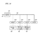
- Fig. 14 is a configuration diagram of a related-art power control system disclosed in Patent Document 1
- Fig. 15 is a flow chart showing the processing operation of a device.
- a power line network includes a breaker device 101, a power line 102, outlets 103A to 103D, devices 104 to 106, and a power supply line 107.
- control units of the devices 104 to 106 have detected a trigger caused by power consumption of a certain value or more (S101).
- this is a phenomenon, such as turning-on of a power supply or an increase in a set temperature in the case of an iron, turning-on of a power supply or a change in a set temperature in the case of an air conditioner, or turning-on of a power supply or the start of discharge of an internal microwave in the case of a microwave oven.
- the control unit detects the value of power consumption (referred to as P) necessary for this (S102).
- the power use request message includes a control code indicating that this is a power use request message, and the value of P as the amount of requested power (S103).
- the devices 104 to 106 which have received a use permission message containing the amount of allowed usable power A determine whether it is reasonable to operate themselves with reference to the values of the amount of allowed usable power indicated in the use permission message (S104 to S107). If this value of electric power is a requested value, the consumption of electric power is started with this power consumption (P) without any problem (S108). Even if the allowed power consumption (A) is smaller than the requested value (P), the consumption of electric power is started with the power consumption (A) if it is determined that power consumption of this value is reasonable (S109). If it is determined that the power consumption of this value is not reasonable, performing the consumption of electric power is stopped (S110).
- Patent Document 1 JP-A-10-94199
- An object of the present invention is to provide a power control system and a method and a program for controlling the power control system.
- the power control system includes a power control device including a priority setting section capable of setting the use priority of a home appliance connected wirelessly or via cable or an adapter connected to the home appliance.
- the home appliance or the adapter connected to the home appliance is operated within the usable power based on the inquiry result, whereby the speed of a response to the user operation can be increased.
- the usable power is lower than the required power of the inquiry, a device with a priority lower than the device which has transmitted the inquiry is instructed to reduce the electric power thereof, whereby a device with a higher priority can be used. Further, a shut-off of a breaker can be prevented.
- the present invention provides a power control system comprising: a home appliance connected wirelessly or via cable through a communication network section, or an adapter connected between a commercial power supply and the home appliance; and a power control device, wherein the home appliance or the adapter comprises: a power detecting section configured to measure or obtain power consumption of the home appliance or power consumption of a device connected to the adapter, wherein the power control device comprises: a current detecting section configured to detect a current flowing through one or more electrical systems of the commercial power supply; a voltage detecting section configured to detect a voltage of the commercial power supply; a power calculating section configured to calculate electric power from detection information of the current detecting section and the voltage detecting section; a transceiver section configured to communicate with the home appliance or the adapter connected between the commercial power supply and the home appliance; an upper limit setting section configured to set an upper limit of a current flowing through the current detecting section; a priority setting section configured to set a use priority of the home appliance or the adapter;
- the power control device includes the priority setting section capable of setting the use priority of home appliance connected wirelessly or via cable or an adapter connected to the home appliances. Accordingly, if the power control device sets the setting value of the upper limit setting section as a rated value for shut-off of a breaker, information on the required power to be used is received from the device when the home appliance (including a home appliance connected to the adapter) is operated, and electric power of a device with a lower priority than the operated device is reduced when there is no margin in the current detected by the current detecting section.
- the power control device side does not need to monitor a power consumption state or a setting state such as an operation mode of the operated device.
- an operation or power reduction can be performed according to the received information on the request even if the device side does not perform complicated control processing. Accordingly, since a complicated information processing function is also unnecessary, the system can be built cheaply.
- the present invention provides a power control system comprising: a plurality of home appliances connected wirelessly or via cable through a communication network section; and a power control device, wherein the home appliance comprises: a power detecting section configured to measure or obtain power consumption of the home appliance and output the power consumption as a power signal; a home appliance information communication section configured to perform communication of a power information signal, a power control signal, or home appliance operation information with the power control system and other home appliances through the communication network section; and a home appliance control section configured to control the home appliance based on the power control signal obtained from the home appliance information communication section and the power signal from the power detecting section, wherein the power control device comprises: a current detecting section configured to detect a current flowing through one or more electrical systems of the commercial power supply; a voltage detecting section configured to detect a voltage of the commercial power supply; a power calculating section configured to calculate electric power from detection information of the current detecting section and the voltage detecting section; a power control communication section configured to communicate with the home appliance; a current upper
- the power control section of the power control device controls electric power of a device autonomously. Therefore, since a user does not need to control electric power with his or her hands, the user can save time and effort. In addition, since electric power of a device is controlled according to the priority, a device with a high priority for the user can be used without inconvenience.
- the power control device includes the priority setting section capable of setting the use priority of home appliance connected wirelessly or via cable or an adapter connected to the home appliances. Accordingly, if the power control device sets the setting value of the upper limit setting section as a rated value for shut-off of a breaker, information on the required power to be used is received from the device when the home appliance (including a home appliance connected to the adapter) is operated, and electric power of a device with a lower priority than the operated device is reduced when there is no margin in the current detected by the current detecting section.
- the power control device side does not need to monitor a power consumption state or a setting state such as an operation mode of the operated device.
- an operation or power reduction can be performed according to the received information on the request even if the device side does not perform complicated control processing. Accordingly, since a complicated information processing function is also unnecessary, the system can be built cheaply.
- the power control section of the power control device when a first home appliance which is one of a plurality of home appliances is operated, an inquiry including the operation information is transmitted to the power control device, and the power control section of the power control device outputs a power control signal for reducing a current or electric power to a home appliance, which has a lower priority set by the priority setting section than the first home appliance, when it is determined that reducing a current or electric power is necessary in order to enable the first home appliance to be used.
- time and effort of the user can be saved.
- electric power of a device is controlled according to the priority, a device with a high priority for a user can be used without inconvenience.
- a power control system includes: a home appliance connected wirelessly or via cable through a communication network section, or an adapter connected between a commercial power supply and the home appliance; and a power control device, wherein the home appliance or the adapter includes: a power detecting section configured to measure or obtain power consumption of the home appliance or power consumption of a device connected to the adapter, wherein the power control device includes: a current detecting section configured to detect a current flowing through one or more electrical systems of the commercial power supply; a voltage detecting section configured to detect a voltage of the commercial power supply; a power calculating section configured to calculate electric power from detection information of the current detecting section and the voltage detecting section; a transceiver section configured to communicate with the home appliance or the adapter connected between the commercial power supply and the home appliance; an upper limit setting section configured to set an upper limit of a current flowing through the current detecting section; a priority setting section configured to set a use priority of the home appliance or the adapter; and a power control instructing section configured
- the power control device sets the setting value of the upper limit setting section as a rated value for shut-off of a breaker, information on the required power to be used is received from the device when the home appliance (including a home appliance connected to the adapter) is operated, and electric power of a device with a lower priority than the operated device is reduced when there is no margin in the current detected by the current detecting section. Accordingly, since it is possible to prevent a shut-off of the breaker, it is possible to efficiently use the capacity of a rated current in order to operate the device. In addition, the power control device side does not need to monitor a power consumption state or a setting state such as an operation mode at the device side.
- a second invention especially in the power control device of the first invention, if an operation of the home appliance or an operation of a device connected to the adapter is an operation related to transition to a mode in which power consumption of the device does not increase, the operation of the home appliance or the device connected to the adapter is controlled according to an instruction of the operation without transmitting the inquiry about whether the home appliance or the device can be used to the power control device.
- an inquiry is not always transmitted to the power control device whenever a device is operated, communication traffic can be reduced, and power consumption can be reduced by the reduction in communication traffic.
- a content of the inquiry about whether the home appliance or the device can be used which is transmitted to the power control device includes a required power value
- the inquiry result includes information containing a usable power value.
- one of the home appliances is an IH cooking heater.
- the priority of the IH cooking heater is set to be high, the user does not have to worry about the shut-off of a breaker at the time of cooking for a meal preparation.
- a fifth invention especially in the power control device of the fourth invention, when the IH cooking heater is operated for transition to a mode in which output power thereof increases, an inquiry is transmitted to the power control device together with information including required power.
- the power control device tries to secure the required power by performing a control to reduce electric power of a device with a lower priority than the IH cooking heater so as to use the IH cooking heater as mach as possible. If the priority of the IH cooking heater is set to be high, it is possible to perform control to reduce electric power of a device with a lower priority by operation of the IH cooking heater, so that the IH cooking heater can be used. Therefore, the user does not need to wait until the total power consumption at home is reduced or does not need to go to stop a device, which consumes a large amount of power, at the time of cooking for a meal preparation.
- a seventh invention especially in the power control device of any one of the first to sixth inventions, in a case in which the home appliance or the device connected to the adapter is an air conditioner, when electric power reduction is requested from the power control device, an instruction to change an operation mode of the air conditioner to a fan mode is given. Since this is not stopping the air conditioner but stopping a compressor of the air conditioner by changing the operation mode to the fan mode, power consumption of the air conditioner can be greatly reduced. In addition, even if the user sees the air conditioner, the user does not misunderstand that the air conditioner is stopped because the air conditioner is operating in the fan mode. Accordingly, there is no concern about failure of the air conditioner.
- At least one device included in the power control system includes a display section configured to display information including power consumption of the device collected in the power control system.
- a current exceeding the upper limit set by the upper limit setting section flows or the power consumption of a device with a low priority is reduced, it is notified through the display section. Accordingly, since the user can check the details of the control by watching the display section, the user can see that home appliances and the like operate differently. As a result, the user feels relieved.
- At least one device included in the power control system includes a Web server, and a device such as a personal computer or a television including a Web browser uses the Web browser as a display section to display information containing power consumption collected by the device including the Web server through a network.
- a display device such as liquid crystal display
- a method for controlling a power control system including a home appliance connected through a communication network section or an adapter connected between a commercial power supply and the home appliance, and a power control device.
- the home appliance or the adapter performs: a usable power inquiry transmitting step of transmitting an inquiry to the power control device together with information including required power when the home appliance is operated for transition to a mode in which output power thereof increases; an inquiry result receiving step of receiving an inquiry result; and an operation control step of controlling an operation according to the inquiry result.
- the device side can operate or reduce the power consumption according to the received information even if the device side does not perform complicated control processing. Accordingly, since a complicated information processing function is not necessary either, the system can be built cheaply.
- a method for controlling a power control system including a home appliance connected through a communication network section or an adapter connected between a commercial power supply and the home appliance, and a power control device.
- a method for controlling the IH heater includes: a usable power inquiry transmitting step of transmitting an inquiry to the power control device together with information including required power when the IH heater is operated for transition to a mode in which output power of the IH heater increases; an inquiry result receiving step of receiving an inquiry result; and a device output power deciding step of deciding to operate in a mode within usable power of the inquiry result when required power can not be as the inquiry result.
- the IH cooking heater can operate with an output of level 9 as long as it can be used at the level 9 even if the required power when the user has performed an operation corresponding to the level 10 cannot be secured. Accordingly, the user does not need to wait until the total power consumption at home is reduced or does not need to go to stop a device, which consumes a large amount of power, at the time of cooking for a meal preparation.
- a method for controlling a power control system including a home appliance connected through a communication network section or an adapter connected between a commercial power supply and the home appliance, and a power control device.
- a method for controlling the power control device includes: a priority setting step of setting a use priority of the home appliance or the adapter; a required power receiving step of receiving required power from the home appliance or the adapter; a margin power value calculating step of calculating, when the required power is received, a margin power value with respect to an upper-limit power value which is set based on an electric power value currently measured; a usable power responding step of sending a response to the home appliance or the adapter with the calculated margin power value as a usable power value; and a power reduction request step of outputting an instruction to reduce electric power of a device having a priority lower than the home appliance or the adapter which has transmitted the information regarding the required power, when the usable power is lower than the required power value.
- a program causing a computer to realize at least some of the functions of the power control system of any one of the first to ninth inventions. Moreover, since this is a program, at least some of the refrigerators and the refrigerator systems of the present invention can be easily realized by making hard resources, such as electrical and information devices, a computer, and a server, cooperate with each other. In addition, distribution or installation of a program can be easily performed by recording the program on recording media or distributing a program using a communication line.
- a fourteenth invention there is provided a power control system including a plurality of home appliances connected wirelessly or via cable through a communication network section and a power control device, wherein the home appliance includes: a power detecting section configured to measure or obtain power consumption of the home appliance and output the power consumption as a power signal; a home appliance information communication section configured to perform communication of a power information signal, a power control signal, or home appliance operation information with the power control system and other home appliances through the communication network section; and a home appliance control section configured to control the home appliance based on the power control signal obtained from the home appliance information communication section and the power signal from the power detecting section, wherein the power control device includes: a current detecting section configured to detect a current flowing through one or more electrical systems of the commercial power supply; a voltage detecting section configured to detect a voltage of the commercial power supply; a power calculating section configured to calculate electric power from detection information of the current detecting section and the voltage detecting section; a power control communication section configured to communicate with the home appliance; a
- the power control section of the power control device controls electric power of a device autonomously. Therefore, since a user does not need to control electric power with his or her hands, the user can save time and effort. In addition, since electric power of a device is controlled according to the priority, a device with a high priority for the user can be used without inconvenience.
- the first home appliance when the first home appliance is operated for a transition to a mode in which electric power of a device does not increase, the first home appliance does not transmit the inquiry to the power control device. Accordingly, when electric power of a device does not increase, communication is not performed since it is not necessary to adjust the total electric power. As a result, since it is possible to save useless time taken for communication, control, and the like, more real-time control can be performed.
- the power control section of the power control device stops transmission of the power control signal to the first home appliance until a drop in electric power by control of the home appliance having the lower priority is confirmed, and the first home appliance does not operate in response to the operation until the power control signal from the power control section of the power control device is input. Even if the power control signal is received, it takes time until electric power is actually reduced, in many cases, in order to ensure the quality and long life. Therefore, since electric power of the first home appliance is increased after checking that electric power has actually been decreased, the home appliance with higher reliability can be provided.
- the power control section gradually reduces electric power of the home appliance having the low priority by the power control signal. Accordingly, since electric power is gradually reduced, it is possible to suppress a decrease in user convenience caused by significant power reduction to some extent.
- a time for user action such as location movement or menu change, can be given by controlling electric power gradually over time.
- the power control section of the power control device changes an amount of time variation at the gradual reduction of the electric power of the home appliance having the low priority , according to a type of the target home appliance. Therefore, since a time for which electric power is gradually reduced is changed according to the target home appliances, it is possible to reduce electric power while ensuring the quality of a device with a low priority and increasing the life of the device.
- the power control section gradually increases electric power of the first home appliance by the power control signal. Therefore, since it is possible to realize a home appliance with better rising of electric power, the home appliance with higher user convenience can be provided.
- the power control section changes an amount of time variation at the gradual increase of the electric power of the first home appliance, according to a type of the first home appliance. Therefore, since the rising of electric power changes according to the kind of the first home appliance, it is possible to provide the home appliance with better convenience while ensuring the quality.
- the power control section when the electric power of the first home appliance in operation cannot be secured even though the electric power is reduced by control of the home appliance having the low priority, the power control section outputs electric power not exceeding the power upper limit as maximum power, and the first home appliance operates with the electric power less than the maximum power indicated by the power control signal from the power control section of the power control device. Therefore, even in the case where the first home appliance operates, cutoff by a current limiter does not occur since the power upper limit is not exceeded. As a result, it is possible to provide a home appliance with higher user convenience.
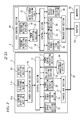
- Fig. 1 is a view showing the system configuration of a power control system of the present invention
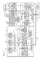
- Fig. 2 is a block diagram showing a power control device of the power control system and an IH cooking heater
- Fig. 3 is a block diagram showing an adapter connected to the power control device of the power control system and an air conditioner.
- a current clamp 2 is interposed on a power line at the input side of a distribution board 1 for supply of single-phase three-wire 200 V into the home, and input currents L1 and L2 are measured by a power control device 3.
- an IH cooking heater 4 as an AC 200 V system
- a device unit 9 and a television 10 are connected to the output line of the distribution board.
- a radio communication device 6 is built in each of the power control device 3, the IH cooking heater 4, and the adapters 5a and 5b so that the information can be transmitted.
- specified low-power radio is used as a radio communication method, and communication is performed using a transmission frequency in a 400 MHz band.
- the device unit 9 since the device unit 9 includes the radio communication device 6, it is possible to intercept the radio communication data transmitted in a space with the same system. Accordingly, the information regarding each device can be collected.
- a Web server is mounted as software in the device unit 9. Accordingly, the device unit 9 is a unit which can be constructed cheaply since a display unit capable of displaying a text, an image, or the like is not provided.
- the device unit 9 and the television 10 are connected to each other through a hub 111 in a general-purpose network.
- the television 10 includes a Web browser, so that the information and the like collected by the device unit 9 can be browsed by screen display using a Web browser of a device with a Web client function, such as the television 10 or a personal computer (not shown), through a general-purpose network.
- the general-purpose network is not particularly designated physically, and any network may be used if it is a network through which transmission and reception using an HTTP protocol are possible.
- the television may be connected to the Internet through a modem/router 112.
- Fig. 2 is a block diagram of the power control device 3 of the power control system and the IH cooking heater 4.
- the power control device 3 includes an L1 current detecting section 11a which measures a current flowing through an L1-phase power system line of single-phase three-wire 200 V, an L2 current detecting section 11b which measures a current flowing through an L2-phase power system line of single-phase three-wire 200 V, and a voltage detecting section 12 which measures a voltage with the L1 phase or the L2 phase.
- a power calculating section 13 calculates a power value on the basis of the current values and the voltage value measured by the L1 current detecting section 11a, the L2 current detecting section 11b, and the voltage detecting section 12.
- an L1-phase input power value, an L2-phase input power value, an input power value of both phases of L1 and L2, and the like are calculated as electric power.
- a control section 14 performs arithmetic processing of the input information or data and generates or transmits a control signal or data.
- a current upper limit setting section 15 sets the upper limit of a current value flowing in the L1 phase or the L2 phase.
- a priority setting section 16 determines the use priority of a device. Setting of the priority is set by a user by providing a DIP switch at the device side, for example. When the device is turned on or the setting is changed, the priority information is transmitted to the power control device 3, the power control device 3 receives the priority information from the device and sets and checks the priority of the device using the priority setting section 16, and a management section 18 updates the priority information of the managed data.
- a priority setting screen may be displayed on a television screen using the device unit 9 or the television 10 so that the user can freely set the priority of a connected device on the television screen using a remote control of the television.
- a power control instructing section 17 outputs a reduction request to a device or an adapter when it is necessary to reduce the power consumption of the device.
- a device or the amount of reduced power which is reduced by the reduction request is determined using the content of an inquiry by operation of a device, the amount of electric power calculated by the power calculating section 13, or the data of the management section 18.
- the management section 18 manages as data the above-described priority information, information regarding power consumption of a device, or a set value or states, such as a power reduction control state of a device, and stores information other than the information regarding power consumption of a device in a nonvolatile memory, such as an EEPROM, so that the data is not erased even if the supply of electric power is stopped.
- a nonvolatile memory such as an EEPROM
- a usable power determining section 19 calculates a difference between the current upper limit set by the current upper limit setting section 15 and the current value measured by the L1 current detecting section 11a or the L2 current detecting section 11b and transmits a usable power value based on the difference in response to the inquiry from a device or to a device which suppresses the use of electric power. That is, this means that the device which has received the usable power value can be further used if it is electric power within the usable power value.
- a breaker of the distribution board may operate.
- a power reduction request section 20 transmits a power reduction request to the device side with the excess as a power reduction value so that the power consumption is reduced. That is, when the device side reduces the power reduction request, the device reduces the power consumption.
- a transceiver section 21 transmits and receives data through a communication network section 10 which performs radio communication.
- the IH cooking heater 4 a heater having functions of three IH coils and one grill is used. On the IH coil, functions such as “heating”, “fried”, “cooking”, and “boiling”, which can be set with output levels of 10 levels, can be used by user's selection.
- functions such as "heating”, “fried”, “cooking”, and “boiling”, which can be set with output levels of 10 levels, can be used by user's selection.
- a grill is controlled by a heater, it is possible to select a cooking mode based on several sequence patterns, such as "grilled fish".
- the principles of heating of an IH cooking heater and the like are known, the explanation and illustration will be omitted.
- the IH cooking heater 4 includes a current detecting section 31 which measures a current flowing through a single-phase power system line of 200 V and a voltage detecting section 32 which measures a voltage.
- a power calculating section 33 calculates the value of power consumption of the IH cooking heater 4 on the basis of the current value and the voltage value measured by the current detecting section 31 and the voltage detecting section 32.
- the control section 34 performs arithmetic processing of the input information or data and generates or transmits a control signal or data.
- An operating section 35 includes switches, such as buttons which select functions of "heating”, “fried”, “cooking”, and “boiling" at each IH coil or the grill of the IH cooking heater.
- an electrostatic switch a TACT SW, a touch panel, or the like may be used as a switch of the operating section 35.
- a display section 36 displays a mode display of a function selected by the operating section 35, an operating state under operation, and the like using an LED or a liquid crystal panel.
- a mode power conversion table 37 is a table for conversion between a mode of each IH coil or a grill and required power (although detailed explanation will be given later, an example of the table is shown in Fig. 6 ).
- a required power transmitting section 38 inquires of the power control device 3 about required power for the user operation referring to the mode power conversion table.
- a device output power deciding section 39 decides a mode of maximum power within the usable power value using the mode transformation table 37 based on a usable power value received in response to the inquiry, and controls the IH coil or the heater to operate in a mode determined by an IHCH control section 40 through the control section 34.
- Fig. 3 is a block diagram showing a power control device of a power control system and an adapter connected to an air conditioner. Since the power control device 3 is the same as that in Fig. 2 , the same reference numeral is given thereto and the explanation will be omitted.
- a remote control transmitting section 41 transmits a remote control signal from a remote control light-emitting element, and can transmit an operation mode such as cooling or heating of the air conditioner 7a, a temperature, the air volume, and the like as a remote control signal.
- a remote control receiving section 42 receives a remote control signal from a remote control light-receiving element, and intercepts a remote control signal transmitted when operating a remote control attached to the air conditioner and stores the remote control signal data. This stored remote control signal data generates a stored remote control signal when canceling a power reduction state and transmits a remote control signal to the air conditioner.
- An air conditioner power reduction control section 43 receives the information regarding reduced power or usable power from the power control device 3 and outputs a remote control signal for power reduction from the remote control transmitting section 41 to the air conditioner when power reduction is necessary. Specifically, the operation mode is changed to a "fan mode".
- An advantage of changing the operation mode to the "fan mode" is that power consumption of the air conditioner can be reduced to about tens of watt since a compressor of the air conditioner is stopped.
- the user sees an indoor unit of the air conditioner, the user can see the wind come out. Accordingly, since the user does not misunderstand that the air conditioner is stopped, there is no concern about failure of the air conditioner.
- the adapter 4 includes a power plug 44 and an outlet 45. By inserting the power plug 44 into the indoor outlet and plugging the air conditioner in the outlet 45, power consumption of the air conditioner can be checked.
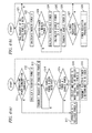
- Fig. 4(a) is a flow chart showing an operation of an IH cooking heater when the IH cooking heater of the power control system is operated
- Fig. 4(b) is a flow chart showing an operation at the power control device side of the power control system when receiving an inquiry from the IH cooking heater when the IH cooking heater is operated
- Fig. 5(a) is a flow chart showing an operation in power reduction processing of the power control device
- Fig. 5(b) is a flow chart showing an operation when an adapter to which an air conditioner is connected receives a power reduction request.
- the device side refers to adapters 5a and 5b to which the IH cooking heater 4 and the air conditioner are connected.
- Fig. 6 is an example of a table for conversion between an operation mode, such as each IH coil or a grill of an IH cooking heater, and required power.
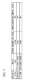
- Fig. 7 is an example of a table managed by a management section of the power control device.
- Fig. 4(a) in the IH cooking heater 4, when an operation for transition to a mode in which the heating level increases is performed (S11), the required power A is calculated (S12).
- the required power A a table regarding a mode and power consumption shown in Fig. 6 is stored, an operate mode is compared with a current mode, and the power difference is treated as required power.
- a difference value 700 W between the level 7 (1600 W) to the level 5 (900 W) is set as the required power A from Fig. 6 .
- the difference value is smaller than 0, the output power decreases. Accordingly, the IH cooking heater operates with the required power A without inquiring of the power control device 3 (S17).
- an inquiry about a device to be used with the required power A is transmitted to the power control device 3 (S13).
- the required power A is compared with the electric power B (S15). If the required power A is smaller, an output mode is determined with reference to the mode power conversion table 37 (S16), and the determined power value is transmitted to the power control device 3 as electric power C determined to be used (S18).
- a level down mode is selected if usable power is smaller than required power.
- automatic cooking control is made such that a device operates within the peak value of power consumption which is equal to or smaller than the usable power.
- the usable power is 500 W when the heating level is increased from the level 5 to the level 7, 500 W is added to the level 5 (900 W) which is a current mode.
- the device since electric power can be used up to 1400 W, the device is made to operate at the maximum level 6 which is equal to or smaller than 1400 W.
- the maximum level 6 which is equal to or smaller than 1400 W.
- the power margin D is calculated by acquiring a difference between the sum of current values detected by the L1 current detecting section 11a and the L2 current detecting section 11b and the current value (in the present embodiment, 30 A) set by the current upper limit setting section 15 and converting the margin from the rated current value into electric power (S22), as shown in Fig. 4(b) .
- Fig. 7 means that an air conditioner 1 operates with 600 W and an air conditioner 2 operates with 500 W when there are two air conditioners as devices with lower priorities than the IH cooking heater.
- a notification is sent from the air conditioner side to a power control device when the power consumption changes by 100 W or more, and the power control device monitors the current power consumption of each device by sending an inquiry to each device periodically every minute.
- each of the two air conditioners in Fig. 7 is connected to an adapter, so that an operation of the air conditioner can be controlled through the remote control transmitting section 41 of the adapter.
- the air conditioner connected to the adapter uses electric power of 20 W since the operation mode is changed to the "fan" mode. Therefore, if electric power of the two air conditioners with low priorities is reduced, maximum 1060 W can be reduced.
- the margin power A and electric power which can be reduced from a device with a low priority, are added, and devices with lower priorities are searched until the required power or more is secured.
- margin power D is smaller than the required power A, it is necessary to reduce electric power of a device with a lower priority than the IH cooking heater (S27). Accordingly, power reduction processing is performed (S28).
- Fig. 5(a) Detailed processing of the power reduction processing is shown in Fig. 5(a) .
- the operation will be described below with reference to Fig. 5(a) and Fig. 5(b) , which is a processing at the adapter side, together.
- a notification that power reduction processing is performed is given by sound or display report that (S31).
- the power control device instead of the power control device, it is also possible to output an instruction of notification wirelessly to the device unit 9 so that the content of the notification can be checked on the television 10 in the case of the configuration shown in Fig. 1 .
- the device to be controlled is a device which has a radio communication device mounted therein and which can be controlled for power reduction.
- the management section 18 searches for devices, which consume 100 W or more, in order of lower priorities (in Fig. 6 , in order of higher priority values) in the table data which manages priorities and power consumption states of devices. If there is a device to be controlled (S33), a "power reduction request" is transmitted to the device through a communication network section 50 (S34).
- the device side calculates the reducible power (S42) and transmits the reducible power value to the power control device 3 (S43). If the electric power can be reduced, a power reduction instruction is output to the device side (S44), and the power consumption is reduced (S45).
- the power control device 3 After transmitting a "power reduction request", a response of "reducible power” is received from the device side (S35). If the received "reducible power” is equal to or larger than 0 W, the device side performs power reduction control to change and update the received power reduction control state of the device to "OFF -> ON" in the table data shown in Fig. 7 (S36).
- the power control device 3 searches for a device to be controlled in order to check whether or not there is a device whose electric power can be reduced (S32), since it is not still smaller than the current upper limit set by the current upper limit setting section 15.
- processing of (S33) to (S37) is similarly repeated as a processing of performing power control of the air conditioner 1 with the next priority. This is performed until reducible power E is secured.
- an operation mode of the air conditioner is changed to a fan mode. Since this is not stopping the air conditioner but stopping a compressor of the air conditioner by changing the operation mode to the fan mode, power consumption of the air conditioner can be greatly reduced. In addition, even if the user sees the air conditioner, the user does not misunderstand that the air conditioner is stopped because the air conditioner is operating in the fan mode. Accordingly, there is no concern about failure of the air conditioner.
- under power reduction control if a display unit such as and LED is provided in a power control device and an adapter or a device under power reduction control and a display indicating "under power reduction control” is given, it is possible to notify the user that the device is operating in a state where electric power of the device has been reduced from the state set by the user. In addition, this may be displayed in detail on a screen of a television through a device unit for notification.
- a device connected to an adapter is an air conditioner.
- a function for shut-off may be mounted in an adapter using a relay, a semiconductor switch, or the like.
- a method may be used in which when a power reduction instruction is received from the power control device 3, the power supply is turned off to reduce electric power.
- a power reduction request is transmitted to each device in the order of lower priorities in order to secure the reducible power E.
- a device whose electric power is to be reduced and the amount of electric power are known, information regarding a plurality of device IDs, by which devices whose electric power is to be reduced can be uniquely distinguished, and information regarding the amount of electric power to be reduced for each device may be included in one-time transmitted telegram. In this case, it is possible to further reduce communication traffic and to increase the responsiveness.
- an adapter is connected to an air conditioner and a power reduction instruction is given from the power control device to the adapter.
- the power control device may directly transmit or receive the data to or from the air conditioner by mounting a radio communication device in the main body of the air conditioner.
- a function of the power reduction control is mounted in the main body of the air conditioner, limited electric power at home can be used more efficiently if the power reduction value requested by the power reduction request from the power reduction device can be reduced by operation change, such as lowering the number of revolutions of a compressor, for example.
- all components of the present embodiment are all or some of constituent components of the power control system, and a program for causing a computer to function as them can be similarly configured.
- constituent components described in the present embodiment may be realized in the form of a program by which hardware resources, such as electrical and information devices including a CPU (or a microcomputer), a RAM, a ROM, storage and recording media, and an I/O, a computer, and a server cooperate with each other.
- hardware resources such as electrical and information devices including a CPU (or a microcomputer), a RAM, a ROM, storage and recording media, and an I/O, a computer, and a server cooperate with each other.
- hardware resources such as electrical and information devices including a CPU (or a microcomputer), a RAM, a ROM, storage and recording media, and an I/O, a computer, and a server cooperate with each other.
- a program distribution and update of a new function or installation of a new function can be easily realized by recording the program on recording media, such as magnetic media or optical media, or distributing the program using a communication line, such as the Internet.
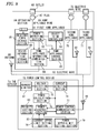
- 61 denotes a first home appliance, and the first home appliance 61 is assumed to have a higher priority when using power than priorities of second and third home appliances 70 and 71.
- 62 denotes a power detecting section, and the power detecting section 62 measures electric power used by the first home appliance 61 and outputs it as a power information signal.
- 65 denotes a home appliance control section, and a power information signal detected by the power detecting section 62 and a home appliance control signal acquired by a home appliance information communication section 64 are input to the home appliance control section 65.
- the home appliance control section 65 outputs a control signal on the basis of the power information signal and the home appliance control signal and controls an object to be controlled 63, for example, a set temperature of an air conditioner and the heating amount of an IH cooking heater.
- 84 denotes an operating section, and the operation of the first home appliance 61 is performed by the user.
- a required power storage section 85 outputs, as a required power signal, required power when an operation using the operating section 84 is performed.
- 86 denotes a device information storage section, and the device information storage section 86 stores the device information regarding the first home appliance 61 and outputs it as a device information signal.
- the home appliance information communication section 64 transmits the power information signal of the power detecting section 62, the control signal of the home appliance control section 5, the required power signal of the required power storage section 85, and the device information signal of the device information storage section 86 to the outside through an antenna 66, and receives the home appliance control signal from the outside through the antenna 66.
- a current is supplied to the first home appliance 61 through an electric wire 72, an outlet 68 set on the electric wire 72, a plug 67, and a home appliance wire 69. As described above, electric power of the first home appliance 61 is measured by the power detecting section 2.
- second and third home appliances 70 and 71 have the same configuration as the first home appliance 61. Accordingly, the second and third home appliances 70 and 71 transmit a power information signal and a control signal to the outside through the antenna 66 and receives a home appliance control signal from the outside through the antenna 66 in the same manner as described above.
- the plugs 67 of the first to third home appliances 61, 70, and 71 are connected to the electric wire 72 through the outlet 68, and electric power is supplied from the outdoor power panel through the power control device 73.
- a current detecting section 74 measures a current of the power control device 73
- a voltage detecting section 75 measures a voltage of the power control device 73.
- the current measured by the current detecting section 74 and the voltage measured by the voltage detecting section 75 are input to a power calculating section 76, and the power calculating section 76 calculates electric power and outputs the value as total electric power.
- a power control communication section 77 is connected to the antenna 66, and transmits or receives the information to or from each home appliance information communication section of the first to third home appliances 61, 70, and 71 through an electric wave 82.
- a current upper limit setting section 78 stores a current value, at which the supply of electric power is stopped due to overcurrent detection performed by a current limiter 81 or a breaker, as a current upper limit.
- a power upper-limit setting section 79 stores a power value, at which the supply of electric power is stopped due to overcurrent detection performed by the current limiter 81, as a power upper limit. Whether to stop the supply of electric power after the current limiter 81 detects either an overcurrent or overpower differs depending on the kind of the current limiter 81.
- 83 denotes a priority setting section.
- the priority setting section 83 stores the priority of power use when connected home appliances, in the example of Fig. 8 , the first to third home appliances 61, 70, and 71 are used and outputs it as a priority signal.
- the first home appliance 61 is set to have a first priority and the other devices are set to have a second priority.
- the communication signal from each home appliance, the priority signal of the priority setting section 23, the current of the current detecting section 74, the electric power of the power calculating section 76, the current upper limit of the current upper limit setting section 78, and the power upper limit of the power upper-limit setting section 79 are input to a power control section 80.
- Electric power of home appliances which can be transmitted or received through an electric wave according to the priorities of home appliances, in the example of Fig. 8 , the first to third home appliances 61, 70, and 71 is determined according to the priorities such that a current flowing through the power control device 73 does not exceed the current upper limit, and it is output to each of the home appliances as a power control signal.
- the first to third home appliances 61, 70, and 71 is determined according to required power of each device and the priorities such that electric power flowing through the power control device 73 does not exceed the power upper limit, and it is output to each of the home appliances as a power control signal.
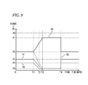
- Fig. 9 is a graph showing electric power P of each home appliance and total power, which is the sum of electric power of home appliances, in a state where a time is set on the horizontal axis and power is set on the vertical axis. In addition, cutoff power P1 of the current limiter 81 is also shown together.
- Electric power P5 that the first home appliance 61 requires, electric power P3 that the second home appliance 70 requires, and electric power P4 that the third home appliance 71 requires are also shown together in Fig. 9 .
- power upper limit P1 of the current limiter 81 is also shown together.
- total power P is electric power P2, that is, P3 + P4 which is the sum of electric power P3 of the second home appliance 70 and electric power P4 of the third home appliance 71.
- a user operates the operating section 84 to request the use of the first home appliance 61, and the required power storage section 85 outputs electric power P5 required for the operation and transmits it to the power control section 80 through the home appliance information communication section 64, the antenna 66, and the power control communication section 77.
- the total power P becomes P3 + P4 + P5 which is the sum of the home appliances. Referring to Fig. 9 , this exceeds the power upper limit P1 which is cutoff power of the current limiter 81. As a result, since a power supply is turned off by the current limiter 81, a problem in that all home appliances cannot be used occurs.
- the power control section 80 controls electric power of each home appliance so that cutoff by the current limiter 81 does not occur. In this case, the power control section 80 performs control such that users of the second and third home appliances 70 and 71 do not feel uncomfortable if possible and durability and quality of the device are not deteriorated.
- Fig. 9 if there is a request for use of the first home appliance 61 at time T1, the total power P exceeds P1, which is the power upper limit, significantly. Accordingly, electric power of the second and third home appliances 70 and 71 with low priorities is reduced. Electric power of the home appliances is controlled such that the second home appliance 70 operates with electric power indicated by 91 in Fig. 9 and the third home appliance 71 operates with electric power indicated by 92.
- the electric power of the first home appliance 61 may not increase depending on an operation. In this case, communication with the power control device 73 is not performed. This is because it is not necessary to control electric power of other devices. Accordingly, useless time taken for communication, control, and the like can be saved.
- the second and third home appliances 70 and 71 are air conditioners and these are used for cooling.
- the current cooling mode In order to reduce electric power of the air conditioner quickly, it is necessary to change the current cooling mode to an OFF mode or a fan mode.
- a sudden mode change will make the user feel uncomfortable. Therefore, by controlling the set temperature such that electric power decreases gradually as shown in Fig. 10 , a decrease in comfort can be prevented to some extent using a method, such as urging a user to move from the installation place of the air conditioner by notifying the user of limitation of electric power caused by the use of the first home appliance 61.
- the power control section 80 can suppress a decrease in user convenience, which is caused by significant power reduction, by reducing electric power gradually by a power control signal of a home appliance with a low priority.
- a time for user action such as location movement or menu change, can be given by controlling electric power gradually over time.
- the power control section 80 can ensure the quality of a device with a low priority and increase the life of the device while reducing electric power by changing a time variation when reducing the electric power of the device with a low priority gradually according to the kind of target home appliances.
- the time variation when reducing electric power of a device with a low priority gradually may become equal to or larger than a predetermined value unexpectedly. Therefore, when the time variation when reducing electric power of a device with a low priority gradually becomes equal to or larger than a predetermined value, the situation is notified to the power control section 80.
- the power control section 80 which has received the notification reduces electric power of another home appliance with a low priority gradually in order to reduce the amount of electric power more quickly.
- the power control section 80 which has received the notification informs the user that it takes a time to reduce the amount of electric power.
- electric power of the first home appliance 61 is controlled such that the total power P does not exceed the power upper limit P1 while observing electric power 31 of the second home appliance 70 and electric power 32 of the third home appliance 71.
- increasing electric power of the first home appliance 61 gradually while observing the electric power of the second and third home appliances 70 and 71 may be preferable rather than increasing the electric power of the first home appliance 61.
- the characteristic of the power control section 80 is to increase electric power by the power control signal of the first home appliance 61, it is possible to realize a home appliance with better rising of electric power. As a result, it is possible to provide the home appliance with higher user convenience.
- the power control device 20 changes a time variation when increasing electric power of the first home appliance 61 gradually according to the kind of the first home appliance 61, the rising of electric power changes according to the kind of the first home appliance 61. Accordingly, it is possible to provide a home appliance with better convenience.
- the power control section 80 outputs electric power, which does not exceed the power upper limit, as maximum power, and the first home appliance 61 operates with the electric power less than the maximum power indicated by the power control section 80 of the power control device 73. Accordingly, even in the case where the first home appliance 61 operates, cutoff by a current limiter does not occur since the power upper limit is not exceeded. As a result, it is possible to provide the home appliance with higher user convenience.
- the power control section 80 transmits a power control signal for reducing electric power to the second and third home appliances 70 and 71 due to communication failure or according to the kind of home appliances, it may take time until a change in electric power of the second and third home appliances 70 and 71 actually occurs. Therefore, a step is added in which transmission of a power control signal to the first home appliance 61 is stopped until power reduction based on control of a home appliance with a low priority is confirmed and the first home appliance 61 does not operate until the power control signal from the power control section 80 of the power control device 73 is input. Accordingly, since the power upper limit P1 is not exceeded, it is possible to provide a highly reliable home appliance.
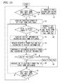
- Fig. 13 electric power of the first home appliance 61 is set to Pw1, electric power of the second home appliance 70 is set to Pw2, and electric power of the third home appliance 71 is set to Pw3.
- required power of the first home appliance 61 is set to P5
- the threshold value of the current limiter 81 is set to P1.
- the total power P is the sum of electric power of the first to third home appliances 61, 70, and 71.
- the second and third home appliances 70 and 71 are normally used, that is, the second and third home appliances 70 and 71 are normally operated without reducing the electric power Pw1 and Pw2 (steps 50 and 51).
- the required power storage section 85 of the first home appliance 61 transmits the required power P5 to the power control section 80 using the communication section (step 52). Then, it is determined whether or not whether expected power P5 + Pw1 + Pw2, which is obtained by adding the required power P5, is larger than the threshold value P1 (step 53). If the expected power P5 + Pw1 + Pw2 is smaller than the threshold value P1, it is determined that power shutdown caused by the current limiter 81 does not occur, and each device is normally used without reducing the electric power (step 54).
- the device information regarding each home appliance is acquired (step 55).
- the electric power Pw2 of the second home appliance 70 and the electric power Pw3 of the third home appliance 71 are reduced according to the device information (step 56).
- the electric power Pw1 of the first home appliance 61 is determined temporarily according to the device information (step 57).
- P1 - Pw2 - Pw3 which is the current margin power of the current limiter 81 is compared with the temporarily determined electric power Pw1 of the first home appliance 61 (step 58).
- the electric power Pw1 is changed to the margin power P1 - Pw2 - Pw3 (step 59). Then, control is made such that the first home appliance 61 operates with the determined electric power Pw1 (step 60).
- Step 61 it is determined whether or not the first home appliance 61 has been turned off. Steps S54 to 61 are repeated if the first home appliance 61 is not OFF, and the process return to step 51 if the first home appliance 61 is OFF (step 51).
- a power control system including a plurality of home appliances connected to each other by cable or wirelessly through a communication network section and a power control device.
- Each of the home appliances includes: a power detecting section which measures or checks power consumption of the home appliance and outputs the power consumption as a power information signal; and a home appliance control section which controls the home appliance on the basis of a power control signal acquired from a home appliance information communication section and a power signal from the power detecting section.
- the home appliance information communication section performs communication of a power information signal, a power control signal, or home appliance operation information with the power control system and other home appliances through the communication network section.
- the power control device includes: a current detecting section which detects a current of one or more electrical systems of the commercial power supply; a voltage detecting section which detects a voltage of the commercial power supply; a power calculating section which calculates electric power from the detection information of the current detecting section and the voltage detecting section; a power control communication section which performs communication with the home appliance; a current upper limit setting section which sets an upper limit of a current flowing through the current detecting section; a power upper limit setting section which sets an upper limit of the electric power calculated by the power calculating section; a priority setting section which sets the use priority of the home appliance; and a power control section to which the current upper limit from the current upper limit setting section, the power upper limit from the power upper limit setting section, the priority from the priority setting section, and the communication information of the home appliance from the power control communication section are input and which determines the electric power value of the home appliance as a power control signal and outputs the power control signal to the power control communication section.
- a power control section of the power control device When a first home appliance which is one of a plurality of home appliances is operated, an inquiry including the operation information is transmitted to the power control device, and a power control section of the power control device outputs a power control signal for reducing a current or electric power to a home appliance, which has a lower priority set by the priority setting section than the first home appliance, when reducing a current or electric power is necessary in order to enable the first home appliance to be used.
- the power control section of the power control device controls electric power of a device autonomously. Therefore, since a user does not need to control electric power with his or her hands, the user can save time and effort. In addition, since electric power of a device is controlled according to the priority, a device with a high priority for the user can be used without inconvenience.
- the operation on the first home appliance is a transition to a mode in which electric power of a device does not increase
- an inquiry is not transmitted to the power control device. Accordingly, when electric power of a device does not increase, communication is not performed since it is not necessary to adjust the total electric power. As a result, since it is possible to save useless time taken for communication, control, and the like, more real-time control can be performed.
- the power control section of the power control device stops transmission of the power control signal to the first home appliance until a drop in electric power by control of a home appliance with a lower priority is confirmed, and the first home appliance does not operate until the power control signal from the power control section of the power control device is input. Even if the power control signal is received, it takes time until electric power is actually reduced, in many cases, in order to ensure the quality and long life. Therefore, since electric power of the first home appliance is increased after checking that electric power has actually been decreased, the home appliance with higher reliability can be provided.
- the power control section reduces electric power gradually by a power control signal of a home appliance with a low priority. Accordingly, since electric power is gradually reduced, it is possible to suppress a decrease in user convenience caused by significant power reduction to some extent.
- a time for user action such as location movement or menu change, can be given by controlling electric power gradually over time.
- the power control section of the power control device changes a time variation when reducing electric power of a home appliance with a low priority gradually according to the kind of target home appliances. Therefore, since a time for which electric power is gradually reduced is changed according to the target home appliances, it is possible to reduce electric power while ensuring the quality of a device with a low priority and increasing the life of the device.
- the power control section increases electric power gradually by the power control signal of the first home appliance. Therefore, since it is possible to realize a home appliance with better rising of electric power, the home appliance with higher user convenience can be provided.
- the power control section changes a time variation when increasing electric power of the first home appliance gradually according to the kind of the first home appliance. Therefore, since the rising of electric power changes according to the kind of the first home appliance, it is possible to provide the home appliance with better convenience while ensuring the quality.
- the power control section when electric power at the time of operation of the first home appliance cannot be secured even if electric power is reduced by control of a home appliance with a low priority, the power control section outputs electric power not exceeding the power upper limit as maximum power, and the first home appliance operates with the electric power less than the maximum power indicated by the power control signal from the power control section of the power control device. Therefore, even in the case where the first home appliance operates, cutoff by a current limiter does not occur since the power upper limit is not exceeded. As a result, it is possible to provide a home appliance with better convenience.
- the present invention is based on Japanese Patent Application (Patent Application No. 2009-000508 ) filed on Jan. 6, 2009 and Japanese Patent Application (Patent Application No. 2009-001292 ) filed on Jan. 7, 2009, the entire content of which is incorporated herein by reference.
- the power control system, the control method of the power control system, and the program according to the present invention may also be applied to a small-scale system at home or a large-scale system outside the home in the same method. Also from the point of view of energy saving, the same method may be applied in order to set the current upper limit.
Landscapes
- Engineering & Computer Science (AREA)
- Power Engineering (AREA)
- Supply And Distribution Of Alternating Current (AREA)
- Remote Monitoring And Control Of Power-Distribution Networks (AREA)
Abstract
Description
- The present invention relates to a power control system configured to control a device in order to prevent a current limiter in a main domestic power line from operating due to an overcurrent to thereby cut off electric power of the device being used, and a method and a program for controlling a power control system.
- In an example of this kind of power control system, a device requests a breaker device for use permission in use, the breaker device determines whether to permit the use, and the device operates within electric power permitted by the breaker device (for example, see Patent Document 1).
-
Fig. 14 is a configuration diagram of a related-art power control system disclosed inPatent Document 1, andFig. 15 is a flow chart showing the processing operation of a device. - In
Fig. 14 , a power line network includes abreaker device 101, apower line 102,outlets 103A to 103D,devices 104 to 106, and apower supply line 107. - In the above configuration, in the operation shown in
Fig. 15 , it is assumed that control units of thedevices 104 to 106 have detected a trigger caused by power consumption of a certain value or more (S101). For example, this is a phenomenon, such as turning-on of a power supply or an increase in a set temperature in the case of an iron, turning-on of a power supply or a change in a set temperature in the case of an air conditioner, or turning-on of a power supply or the start of discharge of an internal microwave in the case of a microwave oven. The control unit detects the value of power consumption (referred to as P) necessary for this (S102). - Then, a power use request message is generated. The power use request message includes a control code indicating that this is a power use request message, and the value of P as the amount of requested power (S103).
- Then, at the device side, the
devices 104 to 106 which have received a use permission message containing the amount of allowed usable power A determine whether it is reasonable to operate themselves with reference to the values of the amount of allowed usable power indicated in the use permission message (S104 to S107). If this value of electric power is a requested value, the consumption of electric power is started with this power consumption (P) without any problem (S108). Even if the allowed power consumption (A) is smaller than the requested value (P), the consumption of electric power is started with the power consumption (A) if it is determined that power consumption of this value is reasonable (S109). If it is determined that the power consumption of this value is not reasonable, performing the consumption of electric power is stopped (S110). - In this way, in the power supply network, it is possible to control the amount of supplied power of a fixed amount or less and to efficiently distribute electric power.
- Patent Document 1:
JP-A-10-94199 - However, in the related-art power control system, when a device receives a use non-permission message, the device inquires about the use is sent again. As a result, two rounds of transmission and reception are required. Moreover, in the case of use non-permission, it is not possible to use a device which a user wants to use unless usable power is increased when the electric power monitored by the breaker device decreases or when the user intentionally performs an operation of reducing electric power of other devices in use. In addition, there has been a disadvantage in that even for a device which a user wants to use, that is, a device with a high priority, if permission to use the device is not given, the device cannot be used.
- An object of the present invention is to provide a power control system and a method and a program for controlling the power control system. The power control system includes a power control device including a priority setting section capable of setting the use priority of a home appliance connected wirelessly or via cable or an adapter connected to the home appliance. In accordance with a result of an inquiry about usable or required power, the home appliance or the adapter connected to the home appliance is operated within the usable power based on the inquiry result, whereby the speed of a response to the user operation can be increased. When the usable power is lower than the required power of the inquiry, a device with a priority lower than the device which has transmitted the inquiry is instructed to reduce the electric power thereof, whereby a device with a higher priority can be used. Further, a shut-off of a breaker can be prevented.
- In order to solve the above-described problems, the present invention provides a power control system comprising: a home appliance connected wirelessly or via cable through a communication network section, or an adapter connected between a commercial power supply and the home appliance; and a power control device, wherein the home appliance or the adapter comprises: a power detecting section configured to measure or obtain power consumption of the home appliance or power consumption of a device connected to the adapter, wherein the power control device comprises: a current detecting section configured to detect a current flowing through one or more electrical systems of the commercial power supply; a voltage detecting section configured to detect a voltage of the commercial power supply; a power calculating section configured to calculate electric power from detection information of the current detecting section and the voltage detecting section; a transceiver section configured to communicate with the home appliance or the adapter connected between the commercial power supply and the home appliance; an upper limit setting section configured to set an upper limit of a current flowing through the current detecting section; a priority setting section configured to set a use priority of the home appliance or the adapter; and a power control instructing section configured to output alarm notification or a power control instruction to the home appliance or the adapter when it is detected that the current flowing through the current detecting section is equal to or larger than a current value set by the upper limit setting section, wherein when the home appliance or the device connected to the adapter is operated, an inquiry about whether the home appliance or the device is usable is transmitted to the power control device, and an operation of the home appliance or the device connected to the adapter is controlled according to the inquiry result, and wherein the power control device outputs a power control instruction to a device which has a lower priority set by the priority setting section than the device which has transmitted the inquiry, based on a content of the inquiry and the detection information of the current detecting section as necessary.
- According to the power control system and the method and program for controlling the power control system of the present invention, the power control device includes the priority setting section capable of setting the use priority of home appliance connected wirelessly or via cable or an adapter connected to the home appliances. Accordingly, if the power control device sets the setting value of the upper limit setting section as a rated value for shut-off of a breaker, information on the required power to be used is received from the device when the home appliance (including a home appliance connected to the adapter) is operated, and electric power of a device with a lower priority than the operated device is reduced when there is no margin in the current detected by the current detecting section. Accordingly, since it is possible to prevent a shut-off of the breaker, it is possible to efficiently use the capacity of a rated current in order to operate the device. In addition, the power control device side does not need to monitor a power consumption state or a setting state such as an operation mode of the operated device. In addition, just by transmitting the information such as usable power to a device, an operation or power reduction can be performed according to the received information on the request even if the device side does not perform complicated control processing. Accordingly, since a complicated information processing function is also unnecessary, the system can be built cheaply.
- Further, the present invention provides a power control system comprising: a plurality of home appliances connected wirelessly or via cable through a communication network section; and a power control device, wherein the home appliance comprises: a power detecting section configured to measure or obtain power consumption of the home appliance and output the power consumption as a power signal; a home appliance information communication section configured to perform communication of a power information signal, a power control signal, or home appliance operation information with the power control system and other home appliances through the communication network section; and a home appliance control section configured to control the home appliance based on the power control signal obtained from the home appliance information communication section and the power signal from the power detecting section, wherein the power control device comprises: a current detecting section configured to detect a current flowing through one or more electrical systems of the commercial power supply; a voltage detecting section configured to detect a voltage of the commercial power supply; a power calculating section configured to calculate electric power from detection information of the current detecting section and the voltage detecting section; a power control communication section configured to communicate with the home appliance; a current upper limit setting section configured to set an upper limit of a current flowing through the current detecting section; a power upper limit setting section configured to set an upper limit of the electric power calculated by the power calculating section; a priority setting section configured to set a use priority of the home appliance; and a power control section configured to receive inputs of the current upper limit from the current upper limit setting section, the power upper limit from the power upper limit setting section, the priority from the priority setting section, and the communication information of the home appliance from the power control communication section, and to decide the electric power value of the home appliance as the power control signal and output the power control signal to the power control communication section, wherein when a first home appliance which is one of the plurality of home appliances is operated, the first home appliance transmits an inquiry including the operation information to the power control device, and wherein the power control section of the power control device outputs the power control signal for reducing a current or electric power to a home appliance having a lower priority set by the priority setting section than the first home appliance, when the power control section determines that it is necessary to reduce a current or electric power in order to enable the first home appliance to be used.
- According to the configuration and the operation of the present invention, the power control section of the power control device controls electric power of a device autonomously. Therefore, since a user does not need to control electric power with his or her hands, the user can save time and effort. In addition, since electric power of a device is controlled according to the priority, a device with a high priority for the user can be used without inconvenience.
- According to the power control system and the method and program for controlling the power control system of the present invention, the power control device includes the priority setting section capable of setting the use priority of home appliance connected wirelessly or via cable or an adapter connected to the home appliances. Accordingly, if the power control device sets the setting value of the upper limit setting section as a rated value for shut-off of a breaker, information on the required power to be used is received from the device when the home appliance (including a home appliance connected to the adapter) is operated, and electric power of a device with a lower priority than the operated device is reduced when there is no margin in the current detected by the current detecting section. Accordingly, since it is possible to prevent a shut-off of the breaker, it is possible to efficiently use the capacity of a rated current in order to operate the device. In addition, the power control device side does not need to monitor a power consumption state or a setting state such as an operation mode of the operated device. In addition, just by transmitting the information such as usable power to a device, an operation or power reduction can be performed according to the received information on the request even if the device side does not perform complicated control processing. Accordingly, since a complicated information processing function is also unnecessary, the system can be built cheaply.
- According to the power control system of the present invention, when a first home appliance which is one of a plurality of home appliances is operated, an inquiry including the operation information is transmitted to the power control device, and the power control section of the power control device outputs a power control signal for reducing a current or electric power to a home appliance, which has a lower priority set by the priority setting section than the first home appliance, when it is determined that reducing a current or electric power is necessary in order to enable the first home appliance to be used. As a result, time and effort of the user can be saved. In addition, since electric power of a device is controlled according to the priority, a device with a high priority for a user can be used without inconvenience.
-
-
Fig. 1 is a view showing the system configuration of a power control system of the present invention. -
Fig. 2 is a block diagram showing a power control device of a power control system and an IH cooking heater. -
Fig. 3 is a block diagram showing an adapter connected to a power control device of a power control system and an air conditioner. -
Fig. 4(a) is a flow chart showing an operation of an IH cooking heater when the IH cooking heater of the power control system is operated, andFig. 4(b) is a flow chart showing an operation at the power control device side of the power control system when receiving an inquiry from the IH cooking heater. -
Fig. 5(a) is a flow chart showing an operation in power reduction processing of the power control device, andFig. 5(b) is a flow chart showing an operation when an adapter to which an air conditioner is connected receives a power reduction request. -
Fig. 6 is a view showing a table for conversion between an operation mode, such as each IH coil or a grill of an IH cooking heater, and required power. -
Fig. 7 is a view showing a table managed by a management section of the power control device. -
Fig. 8 is a view showing the system configuration of a power control system of the present invention. -
Fig. 9 is a view showing the relationship between electric power and time in order to explain the operation of a power control section. -
Fig. 10 is a view showing the relationship between the set temperature and electric power in order to explain the operation of a power control section. -
Fig. 11 is a view showing the relationship between the water temperature and time, which indicates the operation of a power control section. -
Fig. 12 is a view showing the relationship between electric power and time in order to explain the operation of a power control section. -
Fig. 13 is a flow chart showing the operation of a power control section. -
Fig. 14 is a view showing the configuration of a conventional power control system. -
Fig. 15 is a flow chart showing the processing operation of a device in a conventional power control system. - According to a first invention, a power control system includes: a home appliance connected wirelessly or via cable through a communication network section, or an adapter connected between a commercial power supply and the home appliance; and a power control device, wherein the home appliance or the adapter includes: a power detecting section configured to measure or obtain power consumption of the home appliance or power consumption of a device connected to the adapter, wherein the power control device includes: a current detecting section configured to detect a current flowing through one or more electrical systems of the commercial power supply; a voltage detecting section configured to detect a voltage of the commercial power supply; a power calculating section configured to calculate electric power from detection information of the current detecting section and the voltage detecting section; a transceiver section configured to communicate with the home appliance or the adapter connected between the commercial power supply and the home appliance; an upper limit setting section configured to set an upper limit of a current flowing through the current detecting section; a priority setting section configured to set a use priority of the home appliance or the adapter; and a power control instructing section configured to output alarm notification or a power control instruction to the home appliance or the adapter when it is detected that the current flowing through the current detecting section is equal to or larger than a current value set by the upper limit setting section, wherein when the home appliance or the device connected to the adapter is operated, an inquiry about whether the home appliance or the device can be used is transmitted to the power control device, and an operation of the home appliance or the device connected to the adapter is controlled according to the inquiry result, and wherein the power control device outputs a power control instruction to a device which has a lower priority set by the priority setting section than the device which has transmitted the inquiry, based on a content of the inquiry and the detection information of the current detecting section as necessary. If the power control device sets the setting value of the upper limit setting section as a rated value for shut-off of a breaker, information on the required power to be used is received from the device when the home appliance (including a home appliance connected to the adapter) is operated, and electric power of a device with a lower priority than the operated device is reduced when there is no margin in the current detected by the current detecting section. Accordingly, since it is possible to prevent a shut-off of the breaker, it is possible to efficiently use the capacity of a rated current in order to operate the device. In addition, the power control device side does not need to monitor a power consumption state or a setting state such as an operation mode at the device side. In addition, just by transmitting the information such as usable power to a device, an operation or power reduction can be performed according to the received information on the request even if the device side does not perform complicated control processing. Accordingly, since a complicated information processing function is also unnecessary, the system can be built cheaply.
- According to a second invention, especially in the power control device of the first invention, if an operation of the home appliance or an operation of a device connected to the adapter is an operation related to transition to a mode in which power consumption of the device does not increase, the operation of the home appliance or the device connected to the adapter is controlled according to an instruction of the operation without transmitting the inquiry about whether the home appliance or the device can be used to the power control device. In this case, since an inquiry is not always transmitted to the power control device whenever a device is operated, communication traffic can be reduced, and power consumption can be reduced by the reduction in communication traffic.
- According to a third invention, especially in the power control device of the first or second invention, when the home appliance or the device connected to the adapter is operated, a content of the inquiry about whether the home appliance or the device can be used which is transmitted to the power control device includes a required power value, and the inquiry result includes information containing a usable power value. In this case, even if the power control device does not check which kind of device the home appliance or the device connected to the adapter is, the power control device can control the home appliance or the adapter to operate within the usable power value of the inquiry result since the usable power value is included in the inquiry result. Therefore, complicated information transmission and reception or processing is not necessary.
- According to a fourth invention, especially in the power control device of the third invention, one of the home appliances is an IH cooking heater. In this case, if the priority of the IH cooking heater is set to be high, the user does not have to worry about the shut-off of a breaker at the time of cooking for a meal preparation.
- According to a fifth invention, especially in the power control device of the fourth invention, when the IH cooking heater is operated for transition to a mode in which output power thereof increases, an inquiry is transmitted to the power control device together with information including required power. When the required power is added in a current state, and a current exceeding the upper limit set by the high limit setting section is expected to flow, the power control device tries to secure the required power by performing a control to reduce electric power of a device with a lower priority than the IH cooking heater so as to use the IH cooking heater as mach as possible. If the priority of the IH cooking heater is set to be high, it is possible to perform control to reduce electric power of a device with a lower priority by operation of the IH cooking heater, so that the IH cooking heater can be used. Therefore, the user does not need to wait until the total power consumption at home is reduced or does not need to go to stop a device, which consumes a large amount of power, at the time of cooking for a meal preparation.
- According to a sixth invention, especially in the power control device of the fifth invention, the IH cooking heater includes a device output power deciding section configured to decide to operate in a mode within usable power of the inquiry result when required power cannot be secured even though the power control device has controlled the device with the lower priority than the IH cooking heater. For example, when a user can set an output level of ten level (maximum output = 10) heating, the heating level is determined within the usable power and output so that the IH cooking heater operates with an output of
level 9 as long as it can be used at thelevel 9 even if the required power when the user has performed an operation corresponding to thelevel 10 cannot be secured. In this case, "heating", "cooking", "boiling", "fried", and the like using the IH cooking heater can be started with a small amount of power, unlike ON/OFF control. Accordingly, the user does not need to wait until the total power consumption at home is reduced or does not need to go to stop a device, which consumes a large amount of power, at the time of cooking for a meal preparation. In addition, by setting the priority of the IH cooking heater high, it is possible to perform control to reduce electric power of a device with a lower priority by operation of the IH cooking heater, so that the IH cooking heater can be used if possible. - According to a seventh invention, especially in the power control device of any one of the first to sixth inventions, in a case in which the home appliance or the device connected to the adapter is an air conditioner, when electric power reduction is requested from the power control device, an instruction to change an operation mode of the air conditioner to a fan mode is given. Since this is not stopping the air conditioner but stopping a compressor of the air conditioner by changing the operation mode to the fan mode, power consumption of the air conditioner can be greatly reduced. In addition, even if the user sees the air conditioner, the user does not misunderstand that the air conditioner is stopped because the air conditioner is operating in the fan mode. Accordingly, there is no concern about failure of the air conditioner.
- According to an eighth invention, especially in the power control device of any one of the first to seventh inventions, at least one device included in the power control system includes a display section configured to display information including power consumption of the device collected in the power control system. When a current exceeding the upper limit set by the upper limit setting section flows or the power consumption of a device with a low priority is reduced, it is notified through the display section. Accordingly, since the user can check the details of the control by watching the display section, the user can see that home appliances and the like operate differently. As a result, the user feels relieved.
- According to a ninth invention, especially in the power control system of any one of the first to eighth inventions, at least one device included in the power control system includes a Web server, and a device such as a personal computer or a television including a Web browser uses the Web browser as a display section to display information containing power consumption collected by the device including the Web server through a network. In this case, since the home appliances, the adapter, or the power control device does not need to mount a display device, such as liquid crystal display, therein, the home appliances, the adapter, or the power control device can be made cheaply.
- According to a tenth invention, there is provided a method for controlling a power control system including a home appliance connected through a communication network section or an adapter connected between a commercial power supply and the home appliance, and a power control device. In the method, the home appliance or the adapter performs: a usable power inquiry transmitting step of transmitting an inquiry to the power control device together with information including required power when the home appliance is operated for transition to a mode in which output power thereof increases; an inquiry result receiving step of receiving an inquiry result; and an operation control step of controlling an operation according to the inquiry result. In this case, since a device can operate according to the inquiry result from the power control device, the device side can operate or reduce the power consumption according to the received information even if the device side does not perform complicated control processing. Accordingly, since a complicated information processing function is not necessary either, the system can be built cheaply.
- According to an eleventh invention, there is provided a method for controlling a power control system including a home appliance connected through a communication network section or an adapter connected between a commercial power supply and the home appliance, and a power control device. In the method, in a case in which the home appliance is an IH heater, a method for controlling the IH heater includes: a usable power inquiry transmitting step of transmitting an inquiry to the power control device together with information including required power when the IH heater is operated for transition to a mode in which output power of the IH heater increases; an inquiry result receiving step of receiving an inquiry result; and a device output power deciding step of deciding to operate in a mode within usable power of the inquiry result when required power can not be as the inquiry result. For example, when a user can set an output level of ten level (maximum output = 10) heating, the IH cooking heater can operate with an output of
level 9 as long as it can be used at thelevel 9 even if the required power when the user has performed an operation corresponding to thelevel 10 cannot be secured. Accordingly, the user does not need to wait until the total power consumption at home is reduced or does not need to go to stop a device, which consumes a large amount of power, at the time of cooking for a meal preparation. - According to a twelfth invention, there is provided a method for controlling a power control system including a home appliance connected through a communication network section or an adapter connected between a commercial power supply and the home appliance, and a power control device. In the method, a method for controlling the power control device includes: a priority setting step of setting a use priority of the home appliance or the adapter; a required power receiving step of receiving required power from the home appliance or the adapter; a margin power value calculating step of calculating, when the required power is received, a margin power value with respect to an upper-limit power value which is set based on an electric power value currently measured; a usable power responding step of sending a response to the home appliance or the adapter with the calculated margin power value as a usable power value; and a power reduction request step of outputting an instruction to reduce electric power of a device having a priority lower than the home appliance or the adapter which has transmitted the information regarding the required power, when the usable power is lower than the required power value. By outputting a control instruction to the home appliance or the adapter according to the priority, limited electric power at home can be efficiently used.
- According to a thirteenth invention, there is provided a program causing a computer to realize at least some of the functions of the power control system of any one of the first to ninth inventions. Moreover, since this is a program, at least some of the refrigerators and the refrigerator systems of the present invention can be easily realized by making hard resources, such as electrical and information devices, a computer, and a server, cooperate with each other. In addition, distribution or installation of a program can be easily performed by recording the program on recording media or distributing a program using a communication line.
- According to a fourteenth invention, there is provided a power control system including a plurality of home appliances connected wirelessly or via cable through a communication network section and a power control device, wherein the home appliance includes: a power detecting section configured to measure or obtain power consumption of the home appliance and output the power consumption as a power signal; a home appliance information communication section configured to perform communication of a power information signal, a power control signal, or home appliance operation information with the power control system and other home appliances through the communication network section; and a home appliance control section configured to control the home appliance based on the power control signal obtained from the home appliance information communication section and the power signal from the power detecting section, wherein the power control device includes: a current detecting section configured to detect a current flowing through one or more electrical systems of the commercial power supply; a voltage detecting section configured to detect a voltage of the commercial power supply; a power calculating section configured to calculate electric power from detection information of the current detecting section and the voltage detecting section; a power control communication section configured to communicate with the home appliance; a current upper limit setting section configured to set an upper limit of a current flowing through the current detecting section; a power upper limit setting section configured to set an upper limit of the electric power calculated by the power calculating section; a priority setting section configured to set a use priority of the home appliance; and a power control section configured to receive inputs of the current upper limit from the current upper limit setting section, the power upper limit from the power upper limit setting section, the priority from the priority setting section, and the communication information of the home appliance from the power control communication section, and to decide the electric power value of the home appliance as the power control signal and output the power control signal to the power control communication section, wherein when a first home appliance which is one of the plurality of home appliances is operated, the first home appliance transmits an inquiry including the operation information to the power control device, and wherein the power control section of the power control device outputs the power control signal for reducing a current or electric power to a home appliance having a lower priority set by the priority setting section than the first home appliance, when the power control section determines that it is necessary to reduce a current or electric power in order to enable the first home appliance to be used.
- According to the configuration and the operation of the fourteenth invention, the power control section of the power control device controls electric power of a device autonomously. Therefore, since a user does not need to control electric power with his or her hands, the user can save time and effort. In addition, since electric power of a device is controlled according to the priority, a device with a high priority for the user can be used without inconvenience.
- Moreover, according to a fifteenth invention, especially in the fourteenth invention, when the first home appliance is operated for a transition to a mode in which electric power of a device does not increase, the first home appliance does not transmit the inquiry to the power control device. Accordingly, when electric power of a device does not increase, communication is not performed since it is not necessary to adjust the total electric power. As a result, since it is possible to save useless time taken for communication, control, and the like, more real-time control can be performed.
- Moreover, according to a sixteenth invention, especially in the fourteenth and fifteenth inventions, the power control section of the power control device stops transmission of the power control signal to the first home appliance until a drop in electric power by control of the home appliance having the lower priority is confirmed, and the first home appliance does not operate in response to the operation until the power control signal from the power control section of the power control device is input. Even if the power control signal is received, it takes time until electric power is actually reduced, in many cases, in order to ensure the quality and long life. Therefore, since electric power of the first home appliance is increased after checking that electric power has actually been decreased, the home appliance with higher reliability can be provided.
- Moreover, according to a seventeenth invention, especially in addition to any one of the fourteenth to sixteenth inventions, the power control section gradually reduces electric power of the home appliance having the low priority by the power control signal. Accordingly, since electric power is gradually reduced, it is possible to suppress a decrease in user convenience caused by significant power reduction to some extent. In addition, a time for user action, such as location movement or menu change, can be given by controlling electric power gradually over time.
- Moreover, according to an eighteenth invention, especially in addition to the seventeenth invention, the power control section of the power control device changes an amount of time variation at the gradual reduction of the electric power of the home appliance having the low priority , according to a type of the target home appliance. Therefore, since a time for which electric power is gradually reduced is changed according to the target home appliances, it is possible to reduce electric power while ensuring the quality of a device with a low priority and increasing the life of the device.
- Moreover, according to a nineteenth invention, especially in addition to any one of the fourteenth to eighteenth inventions, the power control section gradually increases electric power of the first home appliance by the power control signal. Therefore, since it is possible to realize a home appliance with better rising of electric power, the home appliance with higher user convenience can be provided.
- Moreover, according to a twentieth invention, especially in addition to the seventeenth invention, the power control section changes an amount of time variation at the gradual increase of the electric power of the first home appliance, according to a type of the first home appliance. Therefore, since the rising of electric power changes according to the kind of the first home appliance, it is possible to provide the home appliance with better convenience while ensuring the quality.
- Moreover, according to a twenty-first invention, especially in addition to any one of the fourteenth to twentieth inventions, when the electric power of the first home appliance in operation cannot be secured even though the electric power is reduced by control of the home appliance having the low priority, the power control section outputs electric power not exceeding the power upper limit as maximum power, and the first home appliance operates with the electric power less than the maximum power indicated by the power control signal from the power control section of the power control device. Therefore, even in the case where the first home appliance operates, cutoff by a current limiter does not occur since the power upper limit is not exceeded. As a result, it is possible to provide a home appliance with higher user convenience.
- Hereinafter, embodiments of the present invention will be described with reference to the drawings. In addition, these embodiments do not limit the present invention.
-
Fig. 1 is a view showing the system configuration of a power control system of the present invention,Fig. 2 is a block diagram showing a power control device of the power control system and an IH cooking heater, andFig. 3 is a block diagram showing an adapter connected to the power control device of the power control system and an air conditioner. - In a first embodiment of the present invention, a
current clamp 2 is interposed on a power line at the input side of adistribution board 1 for supply of single-phase three-wire 200 V into the home, and input currents L1 and L2 are measured by apower control device 3. - In addition, an
IH cooking heater 4 as an AC 200 V system, anadapter 5a to which an air conditioner is connected in L1 phase, adryer 8, and anadapter 5b to which an air conditioner is connected in L2 phase as an AC 100 V system, and adevice unit 9 and atelevision 10 are connected to the output line of the distribution board. In addition, aradio communication device 6 is built in each of thepower control device 3, theIH cooking heater 4, and theadapters - In addition, since the
device unit 9 includes theradio communication device 6, it is possible to intercept the radio communication data transmitted in a space with the same system. Accordingly, the information regarding each device can be collected. In addition, a Web server is mounted as software in thedevice unit 9. Accordingly, thedevice unit 9 is a unit which can be constructed cheaply since a display unit capable of displaying a text, an image, or the like is not provided. - In addition, the
device unit 9 and thetelevision 10 are connected to each other through ahub 111 in a general-purpose network. Thetelevision 10 includes a Web browser, so that the information and the like collected by thedevice unit 9 can be browsed by screen display using a Web browser of a device with a Web client function, such as thetelevision 10 or a personal computer (not shown), through a general-purpose network. - In addition, the general-purpose network is not particularly designated physically, and any network may be used if it is a network through which transmission and reception using an HTTP protocol are possible.
- In addition, the television may be connected to the Internet through a modem/
router 112. - In addition, although many other devices are connected at real home, the following explanation will be given using the above configuration for simplicity of explanation.
-
Fig. 2 is a block diagram of thepower control device 3 of the power control system and theIH cooking heater 4. Thepower control device 3 includes an L1current detecting section 11a which measures a current flowing through an L1-phase power system line of single-phase three-wire 200 V, an L2current detecting section 11b which measures a current flowing through an L2-phase power system line of single-phase three-wire 200 V, and avoltage detecting section 12 which measures a voltage with the L1 phase or the L2 phase. Apower calculating section 13 calculates a power value on the basis of the current values and the voltage value measured by the L1current detecting section 11a, the L2current detecting section 11b, and thevoltage detecting section 12. In addition, an L1-phase input power value, an L2-phase input power value, an input power value of both phases of L1 and L2, and the like are calculated as electric power. - A
control section 14 performs arithmetic processing of the input information or data and generates or transmits a control signal or data. - A current upper
limit setting section 15 sets the upper limit of a current value flowing in the L1 phase or the L2 phase. Regarding the setting of the upper limit, it is preferable to set the upper limit as an initial value in advance and to use an input section, such as a switch, or an external terminal to set the upper limit from a dedicated terminal, a personal computer, or the like when a change is necessary. It is assumed that the initial value of 30 A is used in the present embodiment. - A
priority setting section 16 determines the use priority of a device. Setting of the priority is set by a user by providing a DIP switch at the device side, for example. When the device is turned on or the setting is changed, the priority information is transmitted to thepower control device 3, thepower control device 3 receives the priority information from the device and sets and checks the priority of the device using thepriority setting section 16, and amanagement section 18 updates the priority information of the managed data. In addition, as another method, a priority setting screen may be displayed on a television screen using thedevice unit 9 or thetelevision 10 so that the user can freely set the priority of a connected device on the television screen using a remote control of the television. - A power
control instructing section 17 outputs a reduction request to a device or an adapter when it is necessary to reduce the power consumption of the device. A device or the amount of reduced power which is reduced by the reduction request is determined using the content of an inquiry by operation of a device, the amount of electric power calculated by thepower calculating section 13, or the data of themanagement section 18. - The
management section 18 manages as data the above-described priority information, information regarding power consumption of a device, or a set value or states, such as a power reduction control state of a device, and stores information other than the information regarding power consumption of a device in a nonvolatile memory, such as an EEPROM, so that the data is not erased even if the supply of electric power is stopped. - A usable
power determining section 19 calculates a difference between the current upper limit set by the current upperlimit setting section 15 and the current value measured by the L1current detecting section 11a or the L2current detecting section 11b and transmits a usable power value based on the difference in response to the inquiry from a device or to a device which suppresses the use of electric power. That is, this means that the device which has received the usable power value can be further used if it is electric power within the usable power value. - When the current value measured by the L1
current detecting section 11a or the L2current detecting section 11b exceeds the current upper limit set by the current upperlimit setting section 15, a breaker of the distribution board may operate. In this case, a powerreduction request section 20 transmits a power reduction request to the device side with the excess as a power reduction value so that the power consumption is reduced. That is, when the device side reduces the power reduction request, the device reduces the power consumption. - A
transceiver section 21 transmits and receives data through acommunication network section 10 which performs radio communication. - As the
IH cooking heater 4, a heater having functions of three IH coils and one grill is used. On the IH coil, functions such as "heating", "fried", "cooking", and "boiling", which can be set with output levels of 10 levels, can be used by user's selection. In addition, since a grill is controlled by a heater, it is possible to select a cooking mode based on several sequence patterns, such as "grilled fish". In addition, since the principles of heating of an IH cooking heater and the like are known, the explanation and illustration will be omitted. - The
IH cooking heater 4 includes a current detectingsection 31 which measures a current flowing through a single-phase power system line of 200 V and avoltage detecting section 32 which measures a voltage. Apower calculating section 33 calculates the value of power consumption of theIH cooking heater 4 on the basis of the current value and the voltage value measured by the current detectingsection 31 and thevoltage detecting section 32. - The
control section 34 performs arithmetic processing of the input information or data and generates or transmits a control signal or data. - An
operating section 35 includes switches, such as buttons which select functions of "heating", "fried", "cooking", and "boiling" at each IH coil or the grill of the IH cooking heater. - In addition, an electrostatic switch, a TACT SW, a touch panel, or the like may be used as a switch of the
operating section 35. In addition, adisplay section 36 displays a mode display of a function selected by the operatingsection 35, an operating state under operation, and the like using an LED or a liquid crystal panel. - A mode power conversion table 37 is a table for conversion between a mode of each IH coil or a grill and required power (although detailed explanation will be given later, an example of the table is shown in
Fig. 6 ). - A required
power transmitting section 38 inquires of thepower control device 3 about required power for the user operation referring to the mode power conversion table. - A device output
power deciding section 39 decides a mode of maximum power within the usable power value using the mode transformation table 37 based on a usable power value received in response to the inquiry, and controls the IH coil or the heater to operate in a mode determined by anIHCH control section 40 through thecontrol section 34. -
Fig. 3 is a block diagram showing a power control device of a power control system and an adapter connected to an air conditioner. Since thepower control device 3 is the same as that inFig. 2 , the same reference numeral is given thereto and the explanation will be omitted. - In an
adapter 4, the same reference numeral is given to a section having the same function as in theIH cooking heater 4 shown inFig. 2 and a different section will be described. - A remote
control transmitting section 41 transmits a remote control signal from a remote control light-emitting element, and can transmit an operation mode such as cooling or heating of theair conditioner 7a, a temperature, the air volume, and the like as a remote control signal. - A remote
control receiving section 42 receives a remote control signal from a remote control light-receiving element, and intercepts a remote control signal transmitted when operating a remote control attached to the air conditioner and stores the remote control signal data. This stored remote control signal data generates a stored remote control signal when canceling a power reduction state and transmits a remote control signal to the air conditioner. - An air conditioner power
reduction control section 43 receives the information regarding reduced power or usable power from thepower control device 3 and outputs a remote control signal for power reduction from the remotecontrol transmitting section 41 to the air conditioner when power reduction is necessary. Specifically, the operation mode is changed to a "fan mode". An advantage of changing the operation mode to the "fan mode" is that power consumption of the air conditioner can be reduced to about tens of watt since a compressor of the air conditioner is stopped. In addition, when the user sees an indoor unit of the air conditioner, the user can see the wind come out. Accordingly, since the user does not misunderstand that the air conditioner is stopped, there is no concern about failure of the air conditioner. - In addition, the
adapter 4 includes apower plug 44 and anoutlet 45. By inserting thepower plug 44 into the indoor outlet and plugging the air conditioner in theoutlet 45, power consumption of the air conditioner can be checked. - Next, the operation of the power control system of the present invention will be described using flow charts in
Figs. 4(a), 4(b) ,5(a), and 5(b) and data tables inFigs. 6 and7 . -
Fig. 4(a) is a flow chart showing an operation of an IH cooking heater when the IH cooking heater of the power control system is operated, andFig. 4(b) is a flow chart showing an operation at the power control device side of the power control system when receiving an inquiry from the IH cooking heater when the IH cooking heater is operated.Fig. 5(a) is a flow chart showing an operation in power reduction processing of the power control device, andFig. 5(b) is a flow chart showing an operation when an adapter to which an air conditioner is connected receives a power reduction request. In addition, the device side refers toadapters IH cooking heater 4 and the air conditioner are connected.Fig. 6 is an example of a table for conversion between an operation mode, such as each IH coil or a grill of an IH cooking heater, and required power.Fig. 7 is an example of a table managed by a management section of the power control device. - Hereinafter,
Figs. 4(a), 4(b) ,5(a), 5(b) ,6 , and7 will be described together. - In
Fig. 4(a) , in theIH cooking heater 4, when an operation for transition to a mode in which the heating level increases is performed (S11), the required power A is calculated (S12). Regarding the required power A, a table regarding a mode and power consumption shown inFig. 6 is stored, an operate mode is compared with a current mode, and the power difference is treated as required power. - For example, when a user performs an operation of increasing the heating level to the level 7 while the IH cooking heater is operating left IH heating at the level 5, a
difference value 700 W between the level 7 (1600 W) to the level 5 (900 W) is set as the required power A fromFig. 6 . When the difference value is smaller than 0, the output power decreases. Accordingly, the IH cooking heater operates with the required power A without inquiring of the power control device 3 (S17). - That is, when an operation for transition to a mode in which the heating level does not increase is performed (S11), useless communication with the power control device is removed by operating the IH cooking heater with the required power A without inquiring of the
power control device 3 about the required power (S17). - After returning to (S12) to calculate the required power A, an inquiry about a device to be used with the required power A is transmitted to the power control device 3 (S13). When usable power B is received from the
power control device 3 as an inquiry result (S14), the required power A is compared with the electric power B (S15). If the required power A is smaller, an output mode is determined with reference to the mode power conversion table 37 (S16), and the determined power value is transmitted to thepower control device 3 as electric power C determined to be used (S18). - In addition, as a method of determining a mode, in the case of "manual setting" shown in
Fig. 6 , a level down mode is selected if usable power is smaller than required power. In the case of "automatic cooking", control is made such that a device operates within the peak value of power consumption which is equal to or smaller than the usable power. In the case where it is not possible to make delicious rice if output power is changed, for example, like a rice cooker, automatic cooking is not started. As an example, assuming that the usable power is 500 W when the heating level is increased from the level 5 to thelevel 7, 500 W is added to the level 5 (900 W) which is a current mode. In this case, since electric power can be used up to 1400 W, the device is made to operate at themaximum level 6 which is equal to or smaller than 1400 W. Undoubtedly, when operating the device in a mode other than an operation instruction, it is preferable to reflect the display of thedisplay section 36 or to give an alarm using a buzzer or the like because the device does not operate at a level that the user has operated. - On the other hand, as processing of the
power control device 3, when the required power A is received from the IH cooking heater 4 (S21), the power margin D is calculated by acquiring a difference between the sum of current values detected by the L1current detecting section 11a and the L2current detecting section 11b and the current value (in the present embodiment, 30 A) set by the current upperlimit setting section 15 and converting the margin from the rated current value into electric power (S22), as shown inFig. 4(b) . - If the margin power D is smaller than the received required power A (S23), there is a possibility that a breaker will shut off because the rated current is exceeded when the IH cooking heater operates with the required power A. For this reason, reducible power E which may be reduced from a device with a lower priority than the IH cooking heater is calculated (S24).
- For example,
Fig. 7 means that anair conditioner 1 operates with 600 W and anair conditioner 2 operates with 500 W when there are two air conditioners as devices with lower priorities than the IH cooking heater. As an example of the operation situation of an air conditioner, a notification is sent from the air conditioner side to a power control device when the power consumption changes by 100 W or more, and the power control device monitors the current power consumption of each device by sending an inquiry to each device periodically every minute. In addition, each of the two air conditioners inFig. 7 is connected to an adapter, so that an operation of the air conditioner can be controlled through the remotecontrol transmitting section 41 of the adapter. - As described above, in the case of power reduction, the air conditioner connected to the adapter uses electric power of 20 W since the operation mode is changed to the "fan" mode. Therefore, if electric power of the two air conditioners with low priorities is reduced, maximum 1060 W can be reduced.
- That is, the margin power A and electric power, which can be reduced from a device with a low priority, are added, and devices with lower priorities are searched until the required power or more is secured.
- As a result, usable power (D + E = B) is calculated by adding the margin power D and the reducible power E (S25), and the usable power B is transmitted to the IH cooking heater (S26).
- When the margin power D is smaller than the required power A, it is necessary to reduce electric power of a device with a lower priority than the IH cooking heater (S27). Accordingly, power reduction processing is performed (S28).
- Detailed processing of the power reduction processing is shown in
Fig. 5(a) . The operation will be described below with reference toFig. 5(a) and Fig. 5(b) , which is a processing at the adapter side, together. - When it is necessary to reduce the power, a notification that power reduction processing is performed is given by sound or display report that (S31). In addition, although not shown, a notification section which can be formed cheaply, such as an LED or a buzzer, is provided in the
power control device 3. - Moreover, instead of the power control device, it is also possible to output an instruction of notification wirelessly to the
device unit 9 so that the content of the notification can be checked on thetelevision 10 in the case of the configuration shown inFig. 1 . - After the notification, processing of selecting a device to be controlled (S32) is performed.
- Here, the device to be controlled is a device which has a radio communication device mounted therein and which can be controlled for power reduction. As shown in
Fig. 6 , themanagement section 18 searches for devices, which consume 100 W or more, in order of lower priorities (inFig. 6 , in order of higher priority values) in the table data which manages priorities and power consumption states of devices. If there is a device to be controlled (S33), a "power reduction request" is transmitted to the device through a communication network section 50 (S34). - On the other hand, when the "power reduction request" is received (S41), the device side calculates the reducible power (S42) and transmits the reducible power value to the power control device 3 (S43). If the electric power can be reduced, a power reduction instruction is output to the device side (S44), and the power consumption is reduced (S45).
- As a specific example, when a user selects an operation in a heating mode of the level 9 (2500 W output expected) of a left IH coil for an IH cooking heater in a state where the IH cooking heater is in a stopped state while the
air conditioner 1 is being used with electric power of 600 W and theair conditioner 2 is being used with electric power of 500 W, total electric power may become 3600 W (600 W + 500 W + 2500 W) exceeding 3000 W equivalent to the rated current of 30 A. Therefore, reduction of 600 W which is the excess from the rated power is requested. - In the case of an adapter to which the
air conditioner 2 is connected, the air conditioner is operating in the "operation mode = heating operation (500 W)". Accordingly, when the adapter receives "electric power to be reduced = 200 W", the adapter outputs an instruction, which is for changing the operation mode of the air conditioner to "fan mode (20W)", from the air conditioner powerreduction control section 43 to the remotecontrol transmitting section 41, and the remotecontrol transmitting section 41 outputs a remote control signal to the air conditioner. Therefore, electric power to be reduced, which is replied from a power-to-be-reduced respondingsection 55, becomes 480 W (500 W before reduction - 20 W after reduction). - The
power control device 3 will be described again. After transmitting a "power reduction request", a response of "reducible power" is received from the device side (S35). If the received "reducible power" is equal to or larger than 0 W, the device side performs power reduction control to change and update the received power reduction control state of the device to "OFF -> ON" in the table data shown inFig. 7 (S36). - Then, if the reducible power received as a response is smaller than the power reduction value requested by the power reduction request (S37), the
power control device 3 searches for a device to be controlled in order to check whether or not there is a device whose electric power can be reduced (S32), since it is not still smaller than the current upper limit set by the current upperlimit setting section 15. In the state shown inFig. 6 , processing of (S33) to (S37) is similarly repeated as a processing of performing power control of theair conditioner 1 with the next priority. This is performed until reducible power E is secured. - By performing such processing, an operation of a breaker at home is prevented so that a device with a high priority set by the user can be used if possible.
- In addition, when a device connected to an adapter is an air conditioner, an operation mode of the air conditioner is changed to a fan mode. Since this is not stopping the air conditioner but stopping a compressor of the air conditioner by changing the operation mode to the fan mode, power consumption of the air conditioner can be greatly reduced. In addition, even if the user sees the air conditioner, the user does not misunderstand that the air conditioner is stopped because the air conditioner is operating in the fan mode. Accordingly, there is no concern about failure of the air conditioner.
- Moreover, regarding "under power reduction control", if a display unit such as and LED is provided in a power control device and an adapter or a device under power reduction control and a display indicating "under power reduction control" is given, it is possible to notify the user that the device is operating in a state where electric power of the device has been reduced from the state set by the user. In addition, this may be displayed in detail on a screen of a television through a device unit for notification.
- Moreover, in the explanation of the present embodiment, a device connected to an adapter is an air conditioner. In the case of a home appliance which can be controlled by a remote control, however, it can be controlled in the same method by setting it to a mode in which power consumption can be greatly reduced, such as "operation mode = fan mode", or a stop mode.
- In addition, in the case of a device which does not have a remote control like home appliances, such as a jar pot or an electric stove, a function for shut-off may be mounted in an adapter using a relay, a semiconductor switch, or the like. In this case, a method may be used in which when a power reduction instruction is received from the
power control device 3, the power supply is turned off to reduce electric power. - In addition, although transmission and reception of data have been performed using specified low-power radio communication, which does not require wires, as the
communication network section 50 in the present embodiment, power line communication or cable connection is also possible. - Moreover, in
Fig. 5(a) of the present embodiment, a power reduction request is transmitted to each device in the order of lower priorities in order to secure the reducible power E. However, since a device whose electric power is to be reduced and the amount of electric power are known, information regarding a plurality of device IDs, by which devices whose electric power is to be reduced can be uniquely distinguished, and information regarding the amount of electric power to be reduced for each device may be included in one-time transmitted telegram. In this case, it is possible to further reduce communication traffic and to increase the responsiveness. - In addition, although the operation when an IH cooking heater set to have a highest priority is operated has been described, two IH cooking heaters may be provided, or it is needless to say that an air conditioner be set to have a high priority.
- In addition, in the present embodiment, an adapter is connected to an air conditioner and a power reduction instruction is given from the power control device to the adapter. However, the power control device may directly transmit or receive the data to or from the air conditioner by mounting a radio communication device in the main body of the air conditioner. In addition, when a function of the power reduction control is mounted in the main body of the air conditioner, limited electric power at home can be used more efficiently if the power reduction value requested by the power reduction request from the power reduction device can be reduced by operation change, such as lowering the number of revolutions of a compressor, for example.
- In addition, all components of the present embodiment are all or some of constituent components of the power control system, and a program for causing a computer to function as them can be similarly configured.
- In addition, the constituent components described in the present embodiment may be realized in the form of a program by which hardware resources, such as electrical and information devices including a CPU (or a microcomputer), a RAM, a ROM, storage and recording media, and an I/O, a computer, and a server cooperate with each other. In the form of a program, distribution and update of a new function or installation of a new function can be easily realized by recording the program on recording media, such as magnetic media or optical media, or distributing the program using a communication line, such as the Internet.
- The configuration of a second embodiment of the present invention will be described with reference to
Fig. 8 . InFig. 8 , 61 denotes a first home appliance, and thefirst home appliance 61 is assumed to have a higher priority when using power than priorities of second andthird home appliances power detecting section 62 measures electric power used by thefirst home appliance 61 and outputs it as a power information signal. 65 denotes a home appliance control section, and a power information signal detected by thepower detecting section 62 and a home appliance control signal acquired by a home applianceinformation communication section 64 are input to the homeappliance control section 65. The homeappliance control section 65 outputs a control signal on the basis of the power information signal and the home appliance control signal and controls an object to be controlled 63, for example, a set temperature of an air conditioner and the heating amount of an IH cooking heater. 84 denotes an operating section, and the operation of thefirst home appliance 61 is performed by the user. A requiredpower storage section 85 outputs, as a required power signal, required power when an operation using theoperating section 84 is performed. In addition, 86 denotes a device information storage section, and the deviceinformation storage section 86 stores the device information regarding thefirst home appliance 61 and outputs it as a device information signal. - The home appliance
information communication section 64 transmits the power information signal of thepower detecting section 62, the control signal of the home appliance control section 5, the required power signal of the requiredpower storage section 85, and the device information signal of the deviceinformation storage section 86 to the outside through anantenna 66, and receives the home appliance control signal from the outside through theantenna 66. - A current is supplied to the
first home appliance 61 through anelectric wire 72, anoutlet 68 set on theelectric wire 72, aplug 67, and ahome appliance wire 69. As described above, electric power of thefirst home appliance 61 is measured by thepower detecting section 2. - In addition, second and
third home appliances first home appliance 61. Accordingly, the second andthird home appliances antenna 66 and receives a home appliance control signal from the outside through theantenna 66 in the same manner as described above. - The
plugs 67 of the first tothird home appliances electric wire 72 through theoutlet 68, and electric power is supplied from the outdoor power panel through thepower control device 73. - A current detecting
section 74 measures a current of thepower control device 73, and avoltage detecting section 75 measures a voltage of thepower control device 73. The current measured by the current detectingsection 74 and the voltage measured by thevoltage detecting section 75 are input to apower calculating section 76, and thepower calculating section 76 calculates electric power and outputs the value as total electric power. A powercontrol communication section 77 is connected to theantenna 66, and transmits or receives the information to or from each home appliance information communication section of the first tothird home appliances electric wave 82. - A current upper
limit setting section 78 stores a current value, at which the supply of electric power is stopped due to overcurrent detection performed by acurrent limiter 81 or a breaker, as a current upper limit. In addition, similarly, a power upper-limit setting section 79 stores a power value, at which the supply of electric power is stopped due to overcurrent detection performed by thecurrent limiter 81, as a power upper limit. Whether to stop the supply of electric power after thecurrent limiter 81 detects either an overcurrent or overpower differs depending on the kind of thecurrent limiter 81. - In addition, 83 denotes a priority setting section. The priority setting section 83 stores the priority of power use when connected home appliances, in the example of
Fig. 8 , the first tothird home appliances Fig. 8 , thefirst home appliance 61 is set to have a first priority and the other devices are set to have a second priority. - The communication signal from each home appliance, the priority signal of the
priority setting section 23, the current of the current detectingsection 74, the electric power of thepower calculating section 76, the current upper limit of the current upperlimit setting section 78, and the power upper limit of the power upper-limit setting section 79 are input to apower control section 80. Electric power of home appliances which can be transmitted or received through an electric wave according to the priorities of home appliances, in the example ofFig. 8 , the first tothird home appliances power control device 73 does not exceed the current upper limit, and it is output to each of the home appliances as a power control signal. - Moreover, similarly, electric power of home appliances which can be transmitted or received through an electric wave according to the priorities of home appliances, in the example of
Fig. 8 , the first tothird home appliances power control device 73 does not exceed the power upper limit, and it is output to each of the home appliances as a power control signal. - Next, the operation of the first embodiment of the present invention will be described using
Figs. 9 to 12 . First, the operation of thepower control section 80 will be described usingFig. 9 . -
Fig. 9 is a graph showing electric power P of each home appliance and total power, which is the sum of electric power of home appliances, in a state where a time is set on the horizontal axis and power is set on the vertical axis. In addition, cutoff power P1 of thecurrent limiter 81 is also shown together. - Electric power P5 that the
first home appliance 61 requires, electric power P3 that thesecond home appliance 70 requires, and electric power P4 that thethird home appliance 71 requires are also shown together inFig. 9 . In addition, power upper limit P1 of thecurrent limiter 81 is also shown together. - In
Fig. 9 , since thefirst home appliance 61 does not operate until time T1, total power P is electric power P2, that is, P3 + P4 which is the sum of electric power P3 of thesecond home appliance 70 and electric power P4 of thethird home appliance 71. - At time T1, a user operates the operating
section 84 to request the use of thefirst home appliance 61, and the requiredpower storage section 85 outputs electric power P5 required for the operation and transmits it to thepower control section 80 through the home applianceinformation communication section 64, theantenna 66, and the powercontrol communication section 77. - Assuming that the
first home appliance 61 is used with the electric power P5, the total power P becomes P3 + P4 + P5 which is the sum of the home appliances. Referring toFig. 9 , this exceeds the power upper limit P1 which is cutoff power of thecurrent limiter 81. As a result, since a power supply is turned off by thecurrent limiter 81, a problem in that all home appliances cannot be used occurs. - Therefore, the
power control section 80 controls electric power of each home appliance so that cutoff by thecurrent limiter 81 does not occur. In this case, thepower control section 80 performs control such that users of the second andthird home appliances - Hereinafter, specific power control will be described. In
Fig. 9 , if there is a request for use of thefirst home appliance 61 at time T1, the total power P exceeds P1, which is the power upper limit, significantly. Accordingly, electric power of the second andthird home appliances second home appliance 70 operates with electric power indicated by 91 inFig. 9 and thethird home appliance 71 operates with electric power indicated by 92. - However, although electric power of the
first home appliance 61 increases significantly in the example ofFig. 9 , the electric power of thefirst home appliance 61 may not increase depending on an operation. In this case, communication with thepower control device 73 is not performed. This is because it is not necessary to control electric power of other devices. Accordingly, useless time taken for communication, control, and the like can be saved. - Here, a method of reducing electric power of the second and
third home appliances Figs. 10 ,11 , and12 . - As an example, it is assumed that the second and
third home appliances Fig. 10 , a decrease in comfort can be prevented to some extent using a method, such as urging a user to move from the installation place of the air conditioner by notifying the user of limitation of electric power caused by the use of thefirst home appliance 61. - Moreover, in the case of short-term pause, changing the set temperature without reducing electric power by setting to shut-off or a fan mode from the relationship between refrigerant and power consumption of an inverter may lead to energy saving as a result since electric power required for the next rising becomes small. In addition, an abrupt change in electric power may cause a problem in durability as can be seen from a decrease in durability of a relay caused by spark at the time of switching.
- Although the above explanation is given using the air conditioner as an example, performing control such that electric power changes gradually without significantly reducing the electric power instantaneously is necessary from the point of view of comfort, energy saving, and durability.
- As another example, in the case of an air conditioner, if it can be seen that electric power of the second and
third home appliances first home appliance 61 is decreased as shown inFig. 9 , operating the air conditioner with P6, which is minimum electric power from which immediate increase in electric power is possible, instead of turning off the power supply may be preferable from the point of view of comfort because electric power returns to the current electric power P3 immediately as shown at time T4 inFig. 9 . That is, it can be seen that setting minimum electric power is preferable occasionally on the assumption that a change in electric power occurs. - Therefore, the
power control section 80 can suppress a decrease in user convenience, which is caused by significant power reduction, by reducing electric power gradually by a power control signal of a home appliance with a low priority. In addition, a time for user action, such as location movement or menu change, can be given by controlling electric power gradually over time. - In addition, changing this variation in the amount of reduction according to the kind of home appliances is preferable from the point of view of comfort and durability. That is, the
power control section 80 can ensure the quality of a device with a low priority and increase the life of the device while reducing electric power by changing a time variation when reducing the electric power of the device with a low priority gradually according to the kind of target home appliances. - In addition, the time variation when reducing electric power of a device with a low priority gradually may become equal to or larger than a predetermined value unexpectedly. Therefore, when the time variation when reducing electric power of a device with a low priority gradually becomes equal to or larger than a predetermined value, the situation is notified to the
power control section 80. In addition, thepower control section 80 which has received the notification reduces electric power of another home appliance with a low priority gradually in order to reduce the amount of electric power more quickly. Alternatively, thepower control section 80 which has received the notification informs the user that it takes a time to reduce the amount of electric power. - As shown in
Fig. 9 , electric power of thefirst home appliance 61 is controlled such that the total power P does not exceed the power upper limit P1 while observingelectric power 31 of thesecond home appliance 70 andelectric power 32 of thethird home appliance 71. At time T3 at which reductions in theelectric power 31 of thesecond home appliance 70 and theelectric power 32 of the third home appliance 7 have ended, increasing electric power of thefirst home appliance 61 gradually while observing the electric power of the second andthird home appliances first home appliance 61. - As an example, when a boiling menu is operated in an IH cooking heater as the
first home appliance 61, it is apparently possible to boil the water in the case of using electric power gradually from time T1 as shown inFig. 11 compared with the case of using electric power from time T3. Therefore, since cooking including boiling ends quickly, it is possible to improve comfort and operability of the user. - However, when a rice cooker which needs large electric power from the beginning is the first home appliance as described above, operating the rice cooker at time T3 may be better than increasing electric power gradually like the IH cooking heater described above in terms of cooking performance that cooked rice is delicious. Accordingly, it can be seen that electric power of the
first home appliance 61 needs to be changed according to the kind of thefirst home appliance 61. - Therefore, since the characteristic of the
power control section 80 is to increase electric power by the power control signal of thefirst home appliance 61, it is possible to realize a home appliance with better rising of electric power. As a result, it is possible to provide the home appliance with higher user convenience. - In addition, since the
power control device 20 changes a time variation when increasing electric power of thefirst home appliance 61 gradually according to the kind of thefirst home appliance 61, the rising of electric power changes according to the kind of thefirst home appliance 61. Accordingly, it is possible to provide a home appliance with better convenience. - In addition, when electric power at the time of operation of the
first home appliance 1 cannot be secured even if electric power is reduced by control of a home appliance with a low priority as described inFig. 9 , thepower control section 80 outputs electric power, which does not exceed the power upper limit, as maximum power, and thefirst home appliance 61 operates with the electric power less than the maximum power indicated by thepower control section 80 of thepower control device 73. Accordingly, even in the case where thefirst home appliance 61 operates, cutoff by a current limiter does not occur since the power upper limit is not exceeded. As a result, it is possible to provide the home appliance with higher user convenience. - In addition, even if the
power control section 80 transmits a power control signal for reducing electric power to the second andthird home appliances third home appliances first home appliance 61 is stopped until power reduction based on control of a home appliance with a low priority is confirmed and thefirst home appliance 61 does not operate until the power control signal from thepower control section 80 of thepower control device 73 is input. Accordingly, since the power upper limit P1 is not exceeded, it is possible to provide a highly reliable home appliance. - Next, the entire operation of the
power control section 80 will be described as an example using a flow chart inFig. 13 . InFig. 13 , electric power of thefirst home appliance 61 is set to Pw1, electric power of thesecond home appliance 70 is set to Pw2, and electric power of thethird home appliance 71 is set to Pw3. In addition, as shown inFig. 9 , required power of thefirst home appliance 61 is set to P5, and the threshold value of thecurrent limiter 81 is set to P1. In addition, the total power P is the sum of electric power of the first tothird home appliances - First, it is checked whether or not the
first home appliance 61 is operating. If thefirst home appliance 61 is not operating, the second andthird home appliances third home appliances - If the
first home appliance 61 is operated by the operatingsection 84, the requiredpower storage section 85 of thefirst home appliance 61 transmits the required power P5 to thepower control section 80 using the communication section (step 52). Then, it is determined whether or not whether expected power P5 + Pw1 + Pw2, which is obtained by adding the required power P5, is larger than the threshold value P1 (step 53). If the expected power P5 + Pw1 + Pw2 is smaller than the threshold value P1, it is determined that power shutdown caused by thecurrent limiter 81 does not occur, and each device is normally used without reducing the electric power (step 54). - If the expected power P5 + Pw1 + Pw2 is larger than the threshold value P1, it is determined that it is necessary to reduce the total electric power, and the device information regarding each home appliance is acquired (step 55). The electric power Pw2 of the
second home appliance 70 and the electric power Pw3 of thethird home appliance 71 are reduced according to the device information (step 56). In addition, the electric power Pw1 of thefirst home appliance 61 is determined temporarily according to the device information (step 57). P1 - Pw2 - Pw3 which is the current margin power of thecurrent limiter 81 is compared with the temporarily determined electric power Pw1 of the first home appliance 61 (step 58). If the electric power Pw1 is larger than the margin power, the electric power Pw1 is changed to the margin power P1 - Pw2 - Pw3 (step 59). Then, control is made such that thefirst home appliance 61 operates with the determined electric power Pw1 (step 60). - Then, it is determined whether or not the
first home appliance 61 has been turned off (step 61). Steps S54 to 61 are repeated if thefirst home appliance 61 is not OFF, and the process return to step 51 if thefirst home appliance 61 is OFF (step 51). - The above-described flow chart shown in
Fig. 13 is an example. In short, it is preferable to control electric power according to the priority. - According to an invention of the second embodiment, there is provided a power control system including a plurality of home appliances connected to each other by cable or wirelessly through a communication network section and a power control device. Each of the home appliances includes: a power detecting section which measures or checks power consumption of the home appliance and outputs the power consumption as a power information signal; and a home appliance control section which controls the home appliance on the basis of a power control signal acquired from a home appliance information communication section and a power signal from the power detecting section. The home appliance information communication section performs communication of a power information signal, a power control signal, or home appliance operation information with the power control system and other home appliances through the communication network section. The power control device includes: a current detecting section which detects a current of one or more electrical systems of the commercial power supply; a voltage detecting section which detects a voltage of the commercial power supply; a power calculating section which calculates electric power from the detection information of the current detecting section and the voltage detecting section; a power control communication section which performs communication with the home appliance; a current upper limit setting section which sets an upper limit of a current flowing through the current detecting section; a power upper limit setting section which sets an upper limit of the electric power calculated by the power calculating section; a priority setting section which sets the use priority of the home appliance; and a power control section to which the current upper limit from the current upper limit setting section, the power upper limit from the power upper limit setting section, the priority from the priority setting section, and the communication information of the home appliance from the power control communication section are input and which determines the electric power value of the home appliance as a power control signal and outputs the power control signal to the power control communication section. When a first home appliance which is one of a plurality of home appliances is operated, an inquiry including the operation information is transmitted to the power control device, and a power control section of the power control device outputs a power control signal for reducing a current or electric power to a home appliance, which has a lower priority set by the priority setting section than the first home appliance, when reducing a current or electric power is necessary in order to enable the first home appliance to be used.
- According to the configuration and the operation of the invention of the second embodiment, the power control section of the power control device controls electric power of a device autonomously. Therefore, since a user does not need to control electric power with his or her hands, the user can save time and effort. In addition, since electric power of a device is controlled according to the priority, a device with a high priority for the user can be used without inconvenience.
- Moreover, according to the invention of the second embodiment, when the operation on the first home appliance is a transition to a mode in which electric power of a device does not increase, an inquiry is not transmitted to the power control device. Accordingly, when electric power of a device does not increase, communication is not performed since it is not necessary to adjust the total electric power. As a result, since it is possible to save useless time taken for communication, control, and the like, more real-time control can be performed.
- Moreover, according to the invention of the second embodiment, the power control section of the power control device stops transmission of the power control signal to the first home appliance until a drop in electric power by control of a home appliance with a lower priority is confirmed, and the first home appliance does not operate until the power control signal from the power control section of the power control device is input. Even if the power control signal is received, it takes time until electric power is actually reduced, in many cases, in order to ensure the quality and long life. Therefore, since electric power of the first home appliance is increased after checking that electric power has actually been decreased, the home appliance with higher reliability can be provided.
- Moreover, according to the invention of the second embodiment, the power control section reduces electric power gradually by a power control signal of a home appliance with a low priority. Accordingly, since electric power is gradually reduced, it is possible to suppress a decrease in user convenience caused by significant power reduction to some extent.
- In addition, a time for user action, such as location movement or menu change, can be given by controlling electric power gradually over time.
- Moreover, according to the invention of the second embodiment, the power control section of the power control device changes a time variation when reducing electric power of a home appliance with a low priority gradually according to the kind of target home appliances. Therefore, since a time for which electric power is gradually reduced is changed according to the target home appliances, it is possible to reduce electric power while ensuring the quality of a device with a low priority and increasing the life of the device.
- Moreover, according to the invention of the second embodiment, the power control section increases electric power gradually by the power control signal of the first home appliance. Therefore, since it is possible to realize a home appliance with better rising of electric power, the home appliance with higher user convenience can be provided.
- Moreover, according to the invention of the second embodiment, the power control section changes a time variation when increasing electric power of the first home appliance gradually according to the kind of the first home appliance. Therefore, since the rising of electric power changes according to the kind of the first home appliance, it is possible to provide the home appliance with better convenience while ensuring the quality.
- Moreover, according to the invention of the second embodiment, when electric power at the time of operation of the first home appliance cannot be secured even if electric power is reduced by control of a home appliance with a low priority, the power control section outputs electric power not exceeding the power upper limit as maximum power, and the first home appliance operates with the electric power less than the maximum power indicated by the power control signal from the power control section of the power control device. Therefore, even in the case where the first home appliance operates, cutoff by a current limiter does not occur since the power upper limit is not exceeded. As a result, it is possible to provide a home appliance with better convenience.
- While the present invention has been described in detail with reference to the specific embodiments, it is apparent to those skilled in the art that various changes and modifications may be made without departing from the spirit and scope of the present invention.
- The present invention is based on Japanese Patent Application (Patent Application No.
2009-000508 2009-001292 - As described above, the power control system, the control method of the power control system, and the program according to the present invention may also be applied to a small-scale system at home or a large-scale system outside the home in the same method. Also from the point of view of energy saving, the same method may be applied in order to set the current upper limit.
-
- 1:
- distribution board
- 2:
- current clamp
- 3:
- power control device
- 4:
- IH cooking heater
- 5a, 5b:
- adapter
- 6:
- radio communication device
- 7a, 7b:
- air conditioner
- 8:
- dryer
- 9:
- device unit
- 10:
- television
- 11a:
- L1 current detecting section
- 11b:
- L2 current detecting section
- 12,
- 32: voltage detecting section
- 13:
- power calculating section
- 14, 34:
- control section
- 15:
- current upper limit setting section
- 16:
- priority setting section
- 17:
- power control instructing section
- 18:
- management section
- 19:
- usable power determining section
- 20:
- power reduction request section
- 21:
- transceiver section
- 31:
- current detecting section
- 33:
- power detecting section
- 35,
- 84: operating section
- 36:
- display section
- 37:
- mode power conversion table
- 38:
- required power transmitting section
- 39:
- device output power deciding section
- 40:
- IHCH control section
- 41:
- remote control transmitting section
- 42:
- remote control receiving section
- 43:
- air conditioner power reduction control section
- 44, 67:
- plug
- 45:
- outlet
- 50:
- communication network section
- 55:
- power-to-be-reduced responding section
- 61:
- first home appliance
- 62:
- power detecting section
- 63:
- object to be controlled
- 64:
- home appliance information communication section
- 65:
- home appliance control section
- 66:
- antenna
- 68,
- 1 03A to 103D: outlet
- 69:
- home appliance wire
- 70:
- second home appliance
- 71:
- third home appliance
- 72:
- electric wire
- 73:
- power control device
- 74:
- current detecting section
- 75:
- voltage detecting section
- 76:
- power calculating section
- 77:
- power control communication section
- 78:
- current upper limit setting section
- 79:
- power upper-limit setting section
- 80:
- power control section
- 81:
- current limiter
- 82:
- electric wave
- 83:
- priority setting section
- 84:
- operating section
- 85:
- required power storage section
- 86:
- device information storage section
- 101:
- breaker device
- 102:
- power line
- 104:
-
device 1 - 105:
-
device 2 - 106:
-
device 3 - 111:
- hub
- 112:
- modem/router
Claims (21)
- A power control system comprising:a home appliance connected wirelessly or via cable through a communication network section, or an adapter connected between a commercial power supply and the home appliance; anda power control device,wherein the home appliance or the adapter comprises:a power detecting section configured to measure or obtain power consumption of the home appliance or power consumption of a device connected to the adapter,wherein the power control device comprises:a current detecting section configured to detect a current flowing through one or more electrical systems of the commercial power supply;a voltage detecting section configured to detect a voltage of the commercial power supply;a power calculating section configured to calculate electric power from detection information of the current detecting section and the voltage detecting section;a transceiver section configured to communicate with the home appliance or the adapter connected between the commercial power supply and the home appliance;an upper limit setting section configured to set an upper limit of a current flowing through the current detecting section;a priority setting section configured to set a use priority of the home appliance or the adapter; anda power control instructing section configured to output alarm notification or a power control instruction to the home appliance or the adapter when it is detected that the current flowing through the current detecting section is equal to or larger than a current value set by the upper limit setting section,wherein when the home appliance or the device connected to the adapter is operated, an inquiry about whether the home appliance or the device is usable is transmitted to the power control device, and an operation of the home appliance or the device connected to the adapter is controlled according to the inquiry result, andwherein the power control device outputs a power control instruction to a device which has a lower priority set by the priority setting section than the device which has transmitted the inquiry, based on a content of the inquiry and the detection information of the current detecting section as necessary.
- The power control system according to claim 1,
wherein if an operation of the home appliance or an operation of a device connected to the adapter is an operation related to transition to a mode in which power consumption of the device does not increase, the operation of the home appliance or the device connected to the adapter is controlled according to an instruction of the operation without transmitting the inquiry about whether the home appliance or the device can be used to the power control device. - The power control system according to claim 1 or 2,
wherein when the home appliance or the device connected to the adapter is operated, a content of the inquiry about whether the home appliance or the device can be used transmitted to the power control device includes a required power value, and the inquiry result includes information containing a usable power value. - The power control system according to claim 3,
wherein one of the home appliances is an IH cooking heater. - The power control system according to claim 4,
wherein when the IH cooking heater is operated for transition to a mode in which output power thereof increases, an inquiry is transmitted to the power control device together with information including required power, and
wherein when the required power is added in a current state, and a current exceeding the upper limit set by the high limit setting section is expected to flow, the power control device tries to secure the required power by performing a control to reduce electric power of a device with a lower priority than the IH cooking heater so as to use the IH cooking heater as mach as possible. - The power control system according to claim 5,
wherein the IH cooking heater comprises a device output power deciding section configured to decide to operate in a mode within usable power of the inquiry result when required power cannot be secured even though the power control device has controlled the device with the lower priority than the IH cooking heater. - The power control system according to any one of claims 1 to 6,
wherein in a case in which the home appliance or the device connected to the adapter is an air conditioner, when electric power reduction is requested from the power control device, an instruction to change an operation mode of the air conditioner to a fan mode is given. - The power control system according to any one of claim 1 to 7,
wherein at least one device included in the power control system comprises a display section configured to display information including power consumption of the device collected in the power control system - The power control system according to any one of claims 1 to 8,
wherein at least one device included in the power control system comprises a Web server, and
wherein a device such as a personal computer or a television comprising a Web browser uses the Web browser as a display section to display information containing power consumption collected by the device comprising the Web server through a network. - A method for controlling a power control system comprising a home appliance connected through a communication network section or an adapter connected between a commercial power supply and the home appliance, and a power control device, said method, performed by the home appliance or the adapter, comprising:a usable power inquiry transmitting step of transmitting an inquiry to the power control device together with information including required power when the home appliance is operated for transition to a mode in which output power thereof increases;an inquiry result receiving step of receiving an inquiry result; andan operation control step of controlling an operation according to the inquiry result.
- A method for controlling a power control system comprising a home appliance connected through a communication network section or an adapter connected between a commercial power supply and the home appliance, and a power control device, said method, performed by the IH heater in a case in which the home appliance is an IH heater, comprising:a usable power inquiry transmitting step of transmitting an inquiry to the power control device together with information including required power when the IH heater is operated for transition to a mode in which output power thereof increases;an inquiry result receiving step of receiving an inquiry result; anda device output power deciding step of deciding to operate in a mode within usable power of the inquiry result when required power can not be as the inquiry result.
- A method for controlling a power control system comprising a home appliance connected through a communication network section or an adapter connected between a commercial power supply and the home appliance, and a power control device, said method, performed by the power control device, comprising:a priority setting step of setting a use priority of the home appliance or the adapter;a required power receiving step of receiving required power from the home appliance or the adapter;a margin power value calculating step of calculating, when the required power is received, a margin power value with respect to an upper-limit power value which is set based on an electric power value currently measured;a usable power responding step of sending a response to the home appliance or the adapter with the calculated margin power value as a usable power value; anda power reduction request step of outputting an instruction to reduce electric power of a device having a priority lower than the home appliance or the adapter which has transmitted the information regarding the required power, when the usable power is lower than the required power value.
- A program causing a computer to realize at least a part of the power control system according to any one of claims 1 to 7.
- A power control system comprising:a plurality of home appliances connected wirelessly or via cable through a communication network section; anda power control device,wherein the home appliance comprises:a power detecting section configured to measure or obtain power consumption of the home appliance and output the power consumption as a power signal;a home appliance information communication section configured to perform communication of a power information signal, a power control signal, or home appliance operation information with the power control system and other home appliances through the communication network section; anda home appliance control section configured to control the home appliance based on the power control signal obtained from the home appliance information communication section and the power signal from the power detecting section,wherein the power control device comprises:a current detecting section configured to detect a current flowing through one or more electrical systems of the commercial power supply;a voltage detecting section configured to detect a voltage of the commercial power supply;a power calculating section configured to calculate electric power from detection information of the current detecting section and the voltage detecting section;a power control communication section configured to communicate with the home appliance;a current upper limit setting section configured to set an upper limit of a current flowing through the current detecting section;a power upper limit setting section configured to set an upper limit of the electric power calculated by the power calculating section;a priority setting section configured to set a use priority of the home appliance; anda power control section configured to receive inputs of the current upper limit from the current upper limit setting section, the power upper limit from the power upper limit setting section, the priority from the priority setting section, and the communication information of the home appliance from the power control communication section, and to decide the electric power value of the home appliance as the power control signal and output the power control signal to the power control communication section,wherein when a first home appliance which is one of the plurality of home appliances is operated, the first home appliance transmits an inquiry including the operation information to the power control device, andwherein the power control section of the power control device outputs the power control signal for reducing a current or electric power to a home appliance having a lower priority set by the priority setting section than the first home appliance, when the power control section determines that it is necessary to reduce a current or electric power in order to enable the first home appliance to be used.
- The power control system according to claim 14,
wherein when the first home appliance is operated for a transition to a mode in which electric power of a device does not increase, the first home appliance does not transmit the inquiry to the power control device. - The power control system according to claim 14 or 15,
wherein the power control section of the power control device stops transmission of the power control signal to the first home appliance until a drop in electric power by control of the home appliance having the lower priority is confirmed, and
wherein the first home appliance does not operate in response to the operation until the power control signal from the power control section of the power control device is input. - The power control system according to any one of claims 14 to 16,
wherein the power control section of the power control device gradually reduces electric power of the home appliance having the low priority by the power control signal. - The power control system according to claim 17,
wherein the power control section of the power control device changes an amount of time variation at the gradual reduction of the electric power of the home appliance having the low priority, according to a type of the target home appliance. - The power control system according to any one of claims 14 to 18,
wherein the power control section of the power control device gradually increases electric power of the first home appliance by the power control signal. - The power control system according to claim 19,
wherein the power control section changes an amount of time variation at the gradual increase of the electric power of the first home appliance, according to a type of the first home appliance. - The power control system according to any one of claims 14 to 20,
wherein when the electric power of the first home appliance in operation cannot be secured even though the electric power is reduced by control of the home appliance having the low priority, the power control section outputs electric power not exceeding the power upper limit as maximum power, and
wherein the first home appliance operates with the electric power less than the maximum power indicated by the power control signal from the power control section of the power control device.
Applications Claiming Priority (3)
| Application Number | Priority Date | Filing Date | Title |
|---|---|---|---|
| JP2009000508A JP5456325B2 (en) | 2009-01-06 | 2009-01-06 | Power control system, control method and program for power control system |
| JP2009001292A JP5462489B2 (en) | 2009-01-07 | 2009-01-07 | Power control system |
| PCT/JP2010/000046 WO2010079747A1 (en) | 2009-01-06 | 2010-01-06 | Power control system and method and program for controlling power control system |
Publications (2)
| Publication Number | Publication Date |
|---|---|
| EP2387128A1 true EP2387128A1 (en) | 2011-11-16 |
| EP2387128A4 EP2387128A4 (en) | 2015-01-07 |
Family
ID=42316513
Family Applications (1)
| Application Number | Title | Priority Date | Filing Date |
|---|---|---|---|
| EP10729167.6A Withdrawn EP2387128A4 (en) | 2009-01-06 | 2010-01-06 | POWER CONTROL SYSTEM AND METHOD AND PROGRAM FOR CONTROLLING THIS SYSTEM |
Country Status (4)
| Country | Link |
|---|---|
| US (1) | US8761950B2 (en) |
| EP (1) | EP2387128A4 (en) |
| CN (1) | CN102341991B (en) |
| WO (1) | WO2010079747A1 (en) |
Cited By (4)
| Publication number | Priority date | Publication date | Assignee | Title |
|---|---|---|---|---|
| EP2638612A2 (en) * | 2010-11-11 | 2013-09-18 | Robert Bosch GmbH | Method for operating a local energy network |
| EP2874264A4 (en) * | 2012-07-13 | 2016-03-30 | Nitto Denko Corp | SYSTEM FOR MANAGING MULTIPLE ON-DEMAND POWER SOURCES, SYSTEM PROGRAM FOR MANAGING MULTIPLE ON-DEMAND POWER SOURCES, AND COMPUTER-READABLE RECORDING MEDIUM ON WHICH THIS PROGRAM IS RECORDED |
| WO2017221066A1 (en) * | 2016-06-23 | 2017-12-28 | Powermatic Technologies Bvba | Smart remote power management method and apparatus |
| CN113545009A (en) * | 2019-05-16 | 2021-10-22 | 深圳市欢太科技有限公司 | Scene operation method, apparatus, electronic device, and computer-readable medium |
Families Citing this family (41)
| Publication number | Priority date | Publication date | Assignee | Title |
|---|---|---|---|---|
| JP5615277B2 (en) | 2009-06-22 | 2014-10-29 | パナソニック株式会社 | Heating cooker, heating cooker control method and program |
| US20110231027A1 (en) * | 2010-03-20 | 2011-09-22 | Amarante Technologies, Inc. | Systems for monitoring power consumption |
| EP2375527B1 (en) * | 2010-04-12 | 2018-09-19 | Samsung Electronics Co., Ltd. | Demand Response Method and Demand Response System |
| GB201014782D0 (en) * | 2010-09-07 | 2010-10-20 | Fibrepoint Ltd | A modular optical data network and related system |
| JP2012094077A (en) * | 2010-10-28 | 2012-05-17 | Toshiba Corp | Household energy management system |
| JP4937401B1 (en) * | 2010-11-16 | 2012-05-23 | 株式会社東芝 | Electronic device and method for calculating input power value of power supply module in the same device |
| JP2013042589A (en) * | 2011-08-12 | 2013-02-28 | Sharp Corp | Power management device and power management system |
| CN102981419A (en) * | 2011-09-06 | 2013-03-20 | 株式会社碧陆斯 | Power supply control system and power supply control method |
| ES2402533B8 (en) * | 2011-10-25 | 2014-10-09 | Teka Industrial, S.A. | COMBINED POWER CONTROL SYSTEM CONSUMED IN AN OVEN AND A VITROCERAMIC HOB |
| US20130178994A1 (en) * | 2012-01-11 | 2013-07-11 | Nagaraju Valluri | Power metering and load control device |
| JP5955581B2 (en) * | 2012-02-23 | 2016-07-20 | 株式会社東芝 | Electric power supply and demand control device and electric power supply and demand control method |
| CN102684303B (en) * | 2012-03-27 | 2014-02-26 | 宋旭 | Intelligent power load batcher and electric equipment control system |
| JP6145669B2 (en) | 2012-03-27 | 2017-06-14 | パナソニックIpマネジメント株式会社 | Power management apparatus and power management system |
| US9465398B2 (en) | 2012-06-20 | 2016-10-11 | Causam Energy, Inc. | System and methods for actively managing electric power over an electric power grid |
| US9207698B2 (en) | 2012-06-20 | 2015-12-08 | Causam Energy, Inc. | Method and apparatus for actively managing electric power over an electric power grid |
| US9461471B2 (en) | 2012-06-20 | 2016-10-04 | Causam Energy, Inc | System and methods for actively managing electric power over an electric power grid and providing revenue grade date usable for settlement |
| CN103236737B (en) * | 2013-02-02 | 2016-01-20 | 无锡杰尔迅科技有限公司 | A kind of Domestic intelligent distribution box |
| EP2819343B1 (en) * | 2013-06-25 | 2016-12-07 | Airbus Operations GmbH | Inherent power-over-data bus signaling for secure operating mode switching |
| CN103472785B (en) * | 2013-09-04 | 2016-04-06 | 苏州市思玛特电力科技有限公司 | A kind of intelligent control algorithm for household energy management system |
| US20150127185A1 (en) * | 2013-11-07 | 2015-05-07 | Panasonic Intellectual Property Management Co., Ltd. | Power supply-demand control method and power supply-demand control apparatus |
| KR102220911B1 (en) * | 2014-01-06 | 2021-02-25 | 엘지전자 주식회사 | Refrigerator and home appliance |
| KR102173371B1 (en) * | 2014-01-06 | 2020-11-03 | 엘지전자 주식회사 | Refrigerator and home appliance |
| WO2015104740A1 (en) * | 2014-01-10 | 2015-07-16 | パナソニックIpマネジメント株式会社 | Control system and distribution board |
| CN104077907A (en) * | 2014-07-10 | 2014-10-01 | 国家电网公司 | Device and method for forwarding electricity consumption information parameters of electric energy meter |
| CN104065094B (en) * | 2014-07-10 | 2017-08-29 | 国家电网公司 | A kind of system and method for electric power virtual energy storage control |
| CN105680443A (en) * | 2014-10-07 | 2016-06-15 | 周杰 | Power control system for preventing short circuit or power failure and working method for power control system |
| CN105743110A (en) * | 2014-10-07 | 2016-07-06 | 周杰 | Operating method for power control system |
| CN104701872B (en) * | 2014-10-07 | 2018-01-02 | 湖南一二三智能科技有限公司 | A kind of electric control system |
| CN105552942A (en) * | 2014-10-07 | 2016-05-04 | 周杰 | Working method of power control system for preventing short circuits or power failure |
| CN105762819A (en) * | 2014-10-07 | 2016-07-13 | 周杰 | Power control system and working method therefor |
| US9696782B2 (en) * | 2015-02-09 | 2017-07-04 | Microsoft Technology Licensing, Llc | Battery parameter-based power management for suppressing power spikes |
| US10158148B2 (en) | 2015-02-18 | 2018-12-18 | Microsoft Technology Licensing, Llc | Dynamically changing internal state of a battery |
| CN106152372B (en) * | 2015-03-24 | 2019-04-16 | 苏州三星电子有限公司 | A kind of air conditioning electric energy control device and method |
| CN104701850B (en) * | 2015-04-06 | 2017-06-30 | 上海优裴伺新能源科技有限公司 | A power control system |
| US10591206B2 (en) * | 2016-04-04 | 2020-03-17 | C. Nelson Manufacturing Company | Method and system for device with eutectic plate |
| CN111061320B (en) * | 2018-10-16 | 2022-06-24 | 青岛海尔洗衣机有限公司 | Control method and control system of water household appliance |
| CN111061227B (en) * | 2018-10-16 | 2021-11-26 | 青岛海尔洗衣机有限公司 | Control method and control system of household appliance |
| CN110007612B (en) * | 2019-03-22 | 2023-06-13 | 青岛经济技术开发区海尔热水器有限公司 | Household appliance power adjusting method and household appliance |
| KR102770637B1 (en) | 2019-09-11 | 2025-02-24 | 삼성전자주식회사 | Electronic apparatus and control method thereof |
| KR102838278B1 (en) * | 2019-12-30 | 2025-07-25 | 엘지전자 주식회사 | Water heater controlled by frequency regulation of inverter |
| WO2021154924A1 (en) | 2020-01-28 | 2021-08-05 | Enphase Energy, Inc. | Method and apparatus for relative value generation of resources based on knapsack algorithms |
Family Cites Families (28)
| Publication number | Priority date | Publication date | Assignee | Title |
|---|---|---|---|---|
| JP3315741B2 (en) * | 1992-12-21 | 2002-08-19 | 三菱電機株式会社 | Demand control device and demand control system |
| US5572438A (en) * | 1995-01-05 | 1996-11-05 | Teco Energy Management Services | Engery management and building automation system |
| JPH1094170A (en) | 1996-09-13 | 1998-04-10 | Toshiba Corp | Power consumption control system |
| JP3402953B2 (en) | 1996-09-13 | 2003-05-06 | 株式会社東芝 | Communication method, communication system and communication device |
| IT1308762B1 (en) | 1999-06-28 | 2002-01-10 | Merloni Elettrodomestici Spa | METHOD OF MANAGEMENT OF ENERGY CONSUMPTION BY HOUSEHOLD APPLIANCES. |
| US6157008A (en) * | 1999-07-08 | 2000-12-05 | Maytag Corporation | Power distribution system for an appliance |
| WO2002013351A1 (en) * | 2000-08-04 | 2002-02-14 | Hitachi, Ltd. | Electric power device controller and working power control system using the same |
| US6868293B1 (en) * | 2000-09-28 | 2005-03-15 | Itron, Inc. | System and method for energy usage curtailment |
| US20030036810A1 (en) * | 2001-08-15 | 2003-02-20 | Petite Thomas D. | System and method for controlling generation over an integrated wireless network |
| JP2003209924A (en) | 2002-01-11 | 2003-07-25 | Ricoh Co Ltd | Power management system |
| US7561977B2 (en) * | 2002-06-13 | 2009-07-14 | Whirlpool Corporation | Total home energy management system |
| JP2004364463A (en) * | 2003-06-06 | 2004-12-24 | Sumitomo Electric Ind Ltd | Power control system |
| US7010363B2 (en) * | 2003-06-13 | 2006-03-07 | Battelle Memorial Institute | Electrical appliance energy consumption control methods and electrical energy consumption systems |
| JP2007215313A (en) | 2006-02-09 | 2007-08-23 | Pure Spirits:Kk | Energy saving support system |
| JP4752708B2 (en) * | 2006-10-02 | 2011-08-17 | パナソニック電工株式会社 | Power monitoring system |
| JP4781221B2 (en) * | 2006-10-05 | 2011-09-28 | 三菱電機株式会社 | Electric equipment power control system in the kitchen |
| JP4501923B2 (en) * | 2006-10-20 | 2010-07-14 | 三菱電機株式会社 | Home energy management system |
| JP2008125295A (en) * | 2006-11-14 | 2008-05-29 | Central Res Inst Of Electric Power Ind | Load selection / blocking method in consumer and load selection / blocking device in consumer |
| AU2008224840B2 (en) * | 2007-03-14 | 2013-10-03 | Zonit Structured Solutions, Llc | Smart NEMA outlets and associated networks |
| JP2008271721A (en) * | 2007-04-23 | 2008-11-06 | Power System:Kk | Power operation system |
| US20080275495A1 (en) | 2007-05-01 | 2008-11-06 | Silver James H | Retrievable medical filter with diverse baskets |
| JP2008306835A (en) * | 2007-06-07 | 2008-12-18 | Sharp Corp | Power control device |
| JP2009001292A (en) | 2007-06-20 | 2009-01-08 | Hitachi Zosen Corp | Method and apparatus for supplying spherical body to container |
| US8700187B2 (en) * | 2007-08-28 | 2014-04-15 | Consert Inc. | Method and apparatus for actively managing consumption of electric power supplied by one or more electric utilities |
| US8190302B2 (en) * | 2008-09-15 | 2012-05-29 | General Electric Company | Load shedding system for an electromechanically controlled oven |
| US8541719B2 (en) * | 2008-09-15 | 2013-09-24 | General Electric Company | System for reduced peak power consumption by a cooking appliance |
| WO2010081241A1 (en) * | 2009-01-19 | 2010-07-22 | 2D2C, Inc. | Electrical power distribution system |
| US20130178994A1 (en) * | 2012-01-11 | 2013-07-11 | Nagaraju Valluri | Power metering and load control device |
-
2010
- 2010-01-06 CN CN201080010839.3A patent/CN102341991B/en not_active Expired - Fee Related
- 2010-01-06 EP EP10729167.6A patent/EP2387128A4/en not_active Withdrawn
- 2010-01-06 WO PCT/JP2010/000046 patent/WO2010079747A1/en not_active Ceased
- 2010-01-06 US US13/143,439 patent/US8761950B2/en not_active Expired - Fee Related
Cited By (6)
| Publication number | Priority date | Publication date | Assignee | Title |
|---|---|---|---|---|
| EP2638612A2 (en) * | 2010-11-11 | 2013-09-18 | Robert Bosch GmbH | Method for operating a local energy network |
| EP2874264A4 (en) * | 2012-07-13 | 2016-03-30 | Nitto Denko Corp | SYSTEM FOR MANAGING MULTIPLE ON-DEMAND POWER SOURCES, SYSTEM PROGRAM FOR MANAGING MULTIPLE ON-DEMAND POWER SOURCES, AND COMPUTER-READABLE RECORDING MEDIUM ON WHICH THIS PROGRAM IS RECORDED |
| WO2017221066A1 (en) * | 2016-06-23 | 2017-12-28 | Powermatic Technologies Bvba | Smart remote power management method and apparatus |
| CN113545009A (en) * | 2019-05-16 | 2021-10-22 | 深圳市欢太科技有限公司 | Scene operation method, apparatus, electronic device, and computer-readable medium |
| EP3961988A4 (en) * | 2019-05-16 | 2022-04-27 | Shenzhen Heytap Technology Corp., Ltd. | SCENARIO OPERATING METHOD AND APPARATUS, ELECTRONIC DEVICE, AND COMPUTER READABLE MEDIA |
| US11782590B2 (en) | 2019-05-16 | 2023-10-10 | Shenzhen Heytap Technology Corp., Ltd. | Scene-operation method, electronic device, and non-transitory computer readable medium |
Also Published As
| Publication number | Publication date |
|---|---|
| US8761950B2 (en) | 2014-06-24 |
| EP2387128A4 (en) | 2015-01-07 |
| CN102341991B (en) | 2014-04-16 |
| US20110270456A1 (en) | 2011-11-03 |
| CN102341991A (en) | 2012-02-01 |
| WO2010079747A1 (en) | 2010-07-15 |
Similar Documents
| Publication | Publication Date | Title |
|---|---|---|
| US8761950B2 (en) | Power control system and method and program for controlling power control system | |
| JP5456325B2 (en) | Power control system, control method and program for power control system | |
| CN102461331B (en) | Cooking device, control method and programme for same | |
| CA2753025C (en) | Household energy management system and method for one or more appliances and power generator | |
| JP5163499B2 (en) | Power control system | |
| KR101801097B1 (en) | Demand response method and demand response system | |
| US9819186B2 (en) | Automated demand response system and method | |
| JP2010075015A (en) | Demand control system for household electric appliance | |
| JP4501923B2 (en) | Home energy management system | |
| JP2011055622A (en) | Ih cooking heater, method for controlling the ih cooking heater and program | |
| JP2012222976A (en) | Power management device and power management method | |
| JP2008306835A (en) | Power control device | |
| CN105207222A (en) | Intelligent electrical load distribution system and method | |
| JP2011239470A (en) | Electric apparatus demand control system | |
| JP5131145B2 (en) | Power control system and control method of power control system | |
| JP2011055623A (en) | Power control system, method for controlling power control system, and program | |
| JP2011204431A (en) | Heating cooker, control method for the same, and program | |
| JP5967543B2 (en) | Controller, power management system and program | |
| JP2008099448A (en) | Power management system for home appliances | |
| KR101485343B1 (en) | Method and apparatus of demand-response electric consumption control for electric equipment not supporting demand-response function | |
| JP5462489B2 (en) | Power control system | |
| JP2011250621A (en) | Power control system | |
| JP2011015512A (en) | Power control system, method of controlling the same, and program | |
| JP2011205822A (en) | Power control system, control method thereof, and program | |
| EP4290137A1 (en) | Appliance system and method for managing an appliance system |
Legal Events
| Date | Code | Title | Description |
|---|---|---|---|
| PUAI | Public reference made under article 153(3) epc to a published international application that has entered the european phase |
Free format text: ORIGINAL CODE: 0009012 |
|
| 17P | Request for examination filed |
Effective date: 20110808 |
|
| AK | Designated contracting states |
Kind code of ref document: A1 Designated state(s): AT BE BG CH CY CZ DE DK EE ES FI FR GB GR HR HU IE IS IT LI LT LU LV MC MK MT NL NO PL PT RO SE SI SK SM TR |
|
| DAX | Request for extension of the european patent (deleted) | ||
| A4 | Supplementary search report drawn up and despatched |
Effective date: 20141208 |
|
| RIC1 | Information provided on ipc code assigned before grant |
Ipc: H02J 3/14 20060101ALN20141202BHEP Ipc: H04Q 9/00 20060101ALI20141202BHEP Ipc: H02J 3/00 20060101ALI20141202BHEP Ipc: H02J 13/00 20060101AFI20141202BHEP |
|
| RAP1 | Party data changed (applicant data changed or rights of an application transferred) |
Owner name: PANASONIC INTELLECTUAL PROPERTY MANAGEMENT CO., LT |
|
| STAA | Information on the status of an ep patent application or granted ep patent |
Free format text: STATUS: THE APPLICATION HAS BEEN WITHDRAWN |
|
| 18W | Application withdrawn |
Effective date: 20161104 |