EP2819343B1 - Inherent power-over-data bus signaling for secure operating mode switching - Google Patents
Inherent power-over-data bus signaling for secure operating mode switching Download PDFInfo
- Publication number
- EP2819343B1 EP2819343B1 EP13173635.7A EP13173635A EP2819343B1 EP 2819343 B1 EP2819343 B1 EP 2819343B1 EP 13173635 A EP13173635 A EP 13173635A EP 2819343 B1 EP2819343 B1 EP 2819343B1
- Authority
- EP
- European Patent Office
- Prior art keywords
- processing unit
- data
- communication
- supply voltage
- network node
- Prior art date
- Legal status (The legal status is an assumption and is not a legal conclusion. Google has not performed a legal analysis and makes no representation as to the accuracy of the status listed.)
- Not-in-force
Links
- 230000011664 signaling Effects 0.000 title 1
- 238000004891 communication Methods 0.000 claims description 101
- 238000000034 method Methods 0.000 claims description 23
- 238000012423 maintenance Methods 0.000 description 3
- 230000001419 dependent effect Effects 0.000 description 2
- 238000005516 engineering process Methods 0.000 description 2
- 238000009434 installation Methods 0.000 description 2
- 230000005540 biological transmission Effects 0.000 description 1
- 230000000694 effects Effects 0.000 description 1
- 230000006855 networking Effects 0.000 description 1
- 238000000926 separation method Methods 0.000 description 1
- 230000003068 static effect Effects 0.000 description 1
Images


Classifications
-
- H—ELECTRICITY
- H04—ELECTRIC COMMUNICATION TECHNIQUE
- H04L—TRANSMISSION OF DIGITAL INFORMATION, e.g. TELEGRAPHIC COMMUNICATION
- H04L41/00—Arrangements for maintenance, administration or management of data switching networks, e.g. of packet switching networks
- H04L41/08—Configuration management of networks or network elements
- H04L41/0803—Configuration setting
- H04L41/0813—Configuration setting characterised by the conditions triggering a change of settings
- H04L41/0816—Configuration setting characterised by the conditions triggering a change of settings the condition being an adaptation, e.g. in response to network events
-
- H—ELECTRICITY
- H04—ELECTRIC COMMUNICATION TECHNIQUE
- H04L—TRANSMISSION OF DIGITAL INFORMATION, e.g. TELEGRAPHIC COMMUNICATION
- H04L12/00—Data switching networks
- H04L12/02—Details
- H04L12/10—Current supply arrangements
-
- G—PHYSICS
- G05—CONTROLLING; REGULATING
- G05F—SYSTEMS FOR REGULATING ELECTRIC OR MAGNETIC VARIABLES
- G05F1/00—Automatic systems in which deviations of an electric quantity from one or more predetermined values are detected at the output of the system and fed back to a device within the system to restore the detected quantity to its predetermined value or values, i.e. retroactive systems
- G05F1/10—Regulating voltage or current
- G05F1/625—Regulating voltage or current wherein it is irrelevant whether the variable actually regulated is ac or dc
-
- H—ELECTRICITY
- H04—ELECTRIC COMMUNICATION TECHNIQUE
- H04L—TRANSMISSION OF DIGITAL INFORMATION, e.g. TELEGRAPHIC COMMUNICATION
- H04L12/00—Data switching networks
- H04L12/02—Details
- H04L12/12—Arrangements for remote connection or disconnection of substations or of equipment thereof
-
- H—ELECTRICITY
- H04—ELECTRIC COMMUNICATION TECHNIQUE
- H04L—TRANSMISSION OF DIGITAL INFORMATION, e.g. TELEGRAPHIC COMMUNICATION
- H04L12/00—Data switching networks
- H04L12/28—Data switching networks characterised by path configuration, e.g. LAN [Local Area Networks] or WAN [Wide Area Networks]
- H04L12/40—Bus networks
- H04L12/40006—Architecture of a communication node
- H04L12/40039—Details regarding the setting of the power status of a node according to activity on the bus
-
- H—ELECTRICITY
- H04—ELECTRIC COMMUNICATION TECHNIQUE
- H04L—TRANSMISSION OF DIGITAL INFORMATION, e.g. TELEGRAPHIC COMMUNICATION
- H04L12/00—Data switching networks
- H04L12/28—Data switching networks characterised by path configuration, e.g. LAN [Local Area Networks] or WAN [Wide Area Networks]
- H04L12/40—Bus networks
- H04L12/40006—Architecture of a communication node
- H04L12/40045—Details regarding the feeding of energy to the node from the bus
-
- H—ELECTRICITY
- H04—ELECTRIC COMMUNICATION TECHNIQUE
- H04L—TRANSMISSION OF DIGITAL INFORMATION, e.g. TELEGRAPHIC COMMUNICATION
- H04L12/00—Data switching networks
- H04L12/28—Data switching networks characterised by path configuration, e.g. LAN [Local Area Networks] or WAN [Wide Area Networks]
- H04L12/40—Bus networks
- H04L2012/40267—Bus for use in transportation systems
- H04L2012/4028—Bus for use in transportation systems the transportation system being an aircraft
-
- Y—GENERAL TAGGING OF NEW TECHNOLOGICAL DEVELOPMENTS; GENERAL TAGGING OF CROSS-SECTIONAL TECHNOLOGIES SPANNING OVER SEVERAL SECTIONS OF THE IPC; TECHNICAL SUBJECTS COVERED BY FORMER USPC CROSS-REFERENCE ART COLLECTIONS [XRACs] AND DIGESTS
- Y02—TECHNOLOGIES OR APPLICATIONS FOR MITIGATION OR ADAPTATION AGAINST CLIMATE CHANGE
- Y02D—CLIMATE CHANGE MITIGATION TECHNOLOGIES IN INFORMATION AND COMMUNICATION TECHNOLOGIES [ICT], I.E. INFORMATION AND COMMUNICATION TECHNOLOGIES AIMING AT THE REDUCTION OF THEIR OWN ENERGY USE
- Y02D30/00—Reducing energy consumption in communication networks
- Y02D30/50—Reducing energy consumption in communication networks in wire-line communication networks, e.g. low power modes or reduced link rate
Definitions
- the invention relates to communication networks in means of transportation.
- the invention relates to a method for secure switching between operating modes of a network system. It is further related to a network node, a data network, and an aircraft comprising such a data network.
- Data networks in means of transportation may be used to provide communication services for a variety of data services.
- a modem data network infrastructure within a means of transportation may be used by aircraft control systems, airline information and service systems, or passenger information and entertainment services.
- aircraft control systems For proper and secure operation of such data networks it may be necessary to adapt and change configurations of network components or network nodes. Because such data networks may carry a variety of essential information and data, which may be critical for a safe operation of the aircraft, a high availability and reliable operation may be of particular importance.
- EP 2 586 230 A2 discloses a static mesh network in or for a cabin of a vehicle, in particular in or for an aircraft cabin, wherein the cabin has a predetermined, known cabin layout, comprising a plurality of network levels arranged hierarchically relative to one another. Due to their relevancy to aircraft safety and reliability, additional functional requirements on data networks in means of transportation may arise.
- WO 2012/055300 A1 describes a long-distant constant-voltage electricity-feeding method with wake-up function and system.
- the change of a configuration of a network component may be seen as one important aspect related to safety and security of a data network in a means of transportation.
- Network components may normally be configured, for example, by sending special commands via the network data infrastructure to the devices.
- the administration or maintenance should therefore only be possible in certain operating modes. Therefore, the operating mode should be switchable, however, at the same time it should be ensured that an unintended switching of the operating mode, for example, from connected service domains, is prevented.
- Software commands via the network may be used to configure devices and change operating modes.
- Other solutions, which use additional encryption, may require higher effort, for instance, for key handling.
- local administration of the devices require access to the devices itself, which may be circumstantial, particularly, if the device is installed behind a panel.
- Other known solutions require a dedicated key line for the mode selection. However, this may require additional costly and weight-intensive cabling.
- a method for changing an operating mode of a processing unit of a network node wherein the processing unit is connected to a communication and supply line for providing data communication and for providing a supply voltage.
- the method comprises the following steps: a communication connection of the processing unit of the network node is established via the communication and supply line. Then, a change of the supply voltage of the communication and supply line is determined by the processing unit. Based on the determined change of the supply voltage, an operation mode of the processing unit is set.
- An advantage of this method may be seen in a safe and secure way to enable or disable a configuration mode of a network component. In other words, an unintended switching into a maintenance or administration mode may be avoided.
- Another advantage may be seen in the use of existing hardware or existing infrastructure, since in many cases, a supply voltage is already provided on a communications cable to supply network components or network nodes within a data network. Therefore, additional installation of hardware components may not be necessary. This may further lower costs, weight, and installation effort.
- operating mode may relate to a certain way, a network device responds to commands and/or a certain way of processing data.
- a network processor may have a normal operating mode, where data is processed and/or forwarded according to the requirements of the connected services.
- an additional defined configuration mode may be implemented, where the device responds to special configuration or administration instructions.
- a “processing unit” may be seen as a network node logic, which may provide intelligent data processing, control of hardware components, and/or other additional functions.
- a network node logic may be a microprocessor specialized for networking services.
- the processing unit may also be adapted to provide data switching for connecting the network node and the processing unit with other network nodes in a data network.
- a "communication and supply line” may be electrical cable adapted to provide transportation of data, for instance, internet protocol packets, and additionally provides a possibility to carry a supply voltage for supplying connected network nodes.
- This combination of supply voltage and data communication capabilities in one physical line may provide advantages in terms of weight, cabling, and cost.
- an Ethernet network often uses an eight-wire-cable, wherein four wires are used for data communication. The remaining unused wire may be utilized for transportation of a supply voltage to the destination network node.
- a two-wire-system may be possible, where a supply voltage and a data communication service are implemented on two wires of a communication and supply line.
- a change of the supply voltage may relate to a simple on-off-pattern, but may also relate to a concrete present value or value range of the supply voltage.
- the setting of the operation mode of the processing unit at least comprises changing between a normal operation mode and a configuration mode.
- the normal operation mode may relate to a typical function during a normal operation, for instance during a flight. In this case, a configuration should remain unchanged to ensure stable operation of the network node.
- a configuration mode may relate to a change of a configuration of a network node or processing unit, for instance, during maintenance of an aircraft on the ground.
- the operation mode is set based on a determination of a predefined present voltage or voltage range of the supply voltage.
- An advantage may be seen in a switching of the operating mode only in the case of a defined voltage change of the supply voltage. In other words, it may be prevented that, for instance, a configuration mode is enabled in case of accidental and unintended voltage changes. This may increase safety and reliability of an operation of the network node.
- a “predefined present voltage” may relate to a measured current value of the supply voltage.
- a “voltage range” may relate to a specifically defined range of values of voltage, which may trigger a change of the operating mode.
- the determination of the voltage value of the supply voltage may be, for instance, done via hardware in the network node or may also be provided externally, for instance, by external hardware or external applications.
- the operation mode of the processing unit is set based on determination of a predefined timely change of the supply voltage.
- An advantage may be seen in an increased security, because only in case that a certain pattern of voltage change is detected, the operation mode is switched. For instance, such a predefined timely change may be a certain number of on-off-cycles during a specific time (e.g. three times on and off during one second).
- the operation mode is set based on a combination of the determined change of the supply voltage and a predefined set of data received by the processing unit via the communication connection.
- An advantage may be seen in an increased security and a lower risk to falsely detect a triggering voltage change and the risk to initiate a false mode switching of the processing unit. In other words, only if a combination of two events occurs, the mode change is performed by the processing unit.
- a "predefined set of data” may relate to, for instance, network configuration commands (e.g. SMTP commands) or other suitable data pattern on the communications channel of the network node and the communications and supply line.
- network configuration commands e.g. SMTP commands
- other suitable data pattern on the communications channel of the network node and the communications and supply line.
- the communication connection of the processing unit to the communication and supply line is established via a data switch of the network node.
- a data switch may be, for instance, a fail-safe-switch of a network, arranged in a daisy-chain topology.
- a data switch may allow a proper functioning and continued data communication between neighboring network nodes in case of a failure of the network node or the processing unit.
- a data switch may be adapted to forward data packets within a network, for instance, an Ethernet-based network.
- the supply voltage of the communication and supply line is provided to the data switch.
- the advantage may be seen in a simpler provisioning of a supply current to the switch without the need of additional local or distributed power supply units.
- data communication and supply voltage may be provided with a single cable connection.
- the processing unit provides a further supply voltage to the data switch.
- An advantage may be seen in an additional redundant power supply in order to avoid a possible failure of the data switch due to, for example, a power outage of the supply voltage of the communication and supply line. This may increase reliability and robustness of an operation of the network node, particularly of the data switch to ensure a continued operation of other network components in the data network.
- the method further comprises the step of connecting the data connection to a previous and a next network node by the data switch. Furthermore, the step of detecting a failure of the processing unit by the data switch is included. Also, the data connection between the previous and the next network node in case of a failure of the processing unit is short-circuited.
- An advantage may be seen in a fail-safe function of the network node, such that in case of a node outage or node failure, a data communication between a previous and a next network node is maintained. Particularly in a daisy-chain topology of a data network such a short-circuiting may be essential to ensure continued data communication between other network nodes within a data network.
- the method further comprises the step of exchanging, by an interface of the processing unit, data with application data services.
- An advantage may be seen in the possibility to connect a variety of different data services, such as aircraft control services, airline information and services, and passenger information and entertainment services.
- These data service domains may commonly use the data communication infrastructure of the data network and/or may access the network through the interface of the processing unit.
- the method further comprises the step of changing the supply voltage by a central server unit, which is connected to the communication and supply line.
- the server may initiate a mode change triggering a voltage change on the supply voltage by controlling the power supply associated with the server.
- the provided supply voltage may be combined into a single communication and supply line along with the data channels.
- the server unit may send additional predefined sets of data, for instance to identify a specific network node, or for commanding the setting of the configuration mode.
- the server unit may be configured to provide a combination of a predefined voltage change and a predefined data pattern or command to trigger a change of the operation mode of the processing unit of the connected network node.
- a network node for a data network which comprises a processing unit, and a sensor for measuring a voltage of a supply voltage in a communication and supply line connected to the processing unit.
- the network node is supplied with the supply voltage from the communication and supply line.
- the processing unit is adapted to establish a communication connection of a processing unit of the network node via the communication and supply line.
- the processing unit is adapted to determine a change of the central supply voltage of a communication and supply line with the sensor.
- the processing unit is furthermore adapted to set an operation mode of the processing unit as a function of the state of the supply voltage.
- the term "sensor” may relate to hardware or software means, which may detect a voltage, for instance in a multi-wire cable.
- the sensor is arranged outside the network node, for instance as part of an external network component.
- a data network which comprises a central server unit, a network node as described above, and a communication and supply line, which is adapted to provide data communication between the central server unit and the network node and to supply a supply voltage from the central server unit.
- the central server unit comprises a central power supply adapted to provide the supply voltage to the communication and supply line. Furthermore, the central server unit comprises a switch for changing the supply voltage supplied to the network node, which may mean generation of on-off pattern, but also changing a voltage value within certain limits.
- an aircraft which comprises a data network as described above.
- the means of transportation may be an aircraft, for example, an airplane.
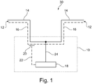
- Fig. 1 shows an example of a network node 10 with a communication and supply line 12 as part of a data network 30.
- the communication and supply line 12 provides a data communication channel 14 and a supply voltage 16.
- the communication and supply line 12 may be, for instance, connected with one end to a previous network node and with another end to a next or following network node.
- the communication and supply line 12 is connected with the network node 10, which comprises a processing unit 18, a sensor 20, a sensor connection 22, and a data connection 24.
- the sensor 20 is adapted for measuring a voltage in the supply voltage 16 in the communication and supply line 12.
- the sensor 20 does not necessarily require a direct electric connection with the supply voltage 16, but may use other principles like electromagnetic or capacitive effects.
- the information provided by the sensor 20 is received by the processing unit 18 through the sensor connection 22.
- the data connection 24 allows the processing unit 18 to communicate with the data communication channel 14 of the communication and supply line 12.
- the processing unit 18 detects a change of the supply voltage 16 by the sensor 20 and may, depending on the determined change of the supply voltage 16, set an operation mode of the processing unit 18.
- the data communication channel 14 may, for instance, be an Ethernet-based data network channel.
- the communication and supply line 12 may integrate the data communication channel 14 and the supply voltage 16 within a common set of wires and one physical cable.
- the supply voltage 16 is switched off for enabling a configuration mode of the processing unit 18.
- the sensor 20 detects this change and provides this information via the sensor connection 22 to the processing unit 18. Based on this detected change of the supply voltage 16, the processing unit switches to a configuration mode.
- the data network 30 comprises a network node 10 with a processing unit 18, a sensor 20, and a sensor connection 22, which allows the processing unit 18 to receive sensor signals from the sensor 20.
- the network node 10 is connected to a first communication and supply line 12A, and is furthermore connected to a second communication and supply line 12B. Both supply lines 12A, 12B provide a supply voltage 16.
- the first communication and supply line 12A comprises a first data communication channel 14A, which provides a data connection between the network node 10 and a server unit 32.
- the second communication and supply line 12B comprises a second data communication channel 14B for providing data communication to a following network node.
- the network node 10 further comprises a data switch 34 with switching elements 36A, 36B, 36C.
- the data switch 34 may be operated as fail-safe switch, which connects the first data communication channel 14A with the second data communication channel 14B, and, furthermore, connects both data communication channels 14A, 14B to the processing unit 18.
- the data switch is adapted to detect a failure of the processing unit 18 and may directly connect the first data communication channel 14A to the second data communication channel 14B, establishing a direct data connection between the two data communication channels 14A, 14B. This may allow a continued data transmission on the data communication channel 14A, 14B, even in the case of a failure of the network node 10, in particular the processing unit 18.
- the switching element 36A short-circuits or bridges both data communication channels 14A, 14B.
- the data communication channel 14A to the processing unit 18 may be interrupted by the switching element 36C.
- the connection of the second data communication channel 14B to the processing unit 18 is interrupted or opened by the switching element 36B, for example, in case of a failure of the processing unit 18.
- the fail-safe data switch 34 may be used in a daisy-chain network topology, as shown in the current example. However, also other network topologies and technologies, such as Ethernet, Token Ring, and others may be used.
- the fail-safe data switch 34 has a connection for supply voltage 38 to the supply voltage 16 of the communication and supply line 12. This allows operating the data switch 34 without a local power supply.
- the fail-safe data switch 34 is powered by a further supply voltage 40 from the processing unit 18. In combination with the connection for supply voltage 38, the further supply voltage may provide a redundant and reliable power supply of the data switch 34.
- the data switch 34 may still be safely operated with the supply voltage 40 provided by the processing unit 18.
- the processing unit 18 is operated with a processing unit supply voltage 42, which may be provided, for instance, by a local power supply at or in the network node 10.
- the processing unit 18 is connected to an interface 44 for connecting application data services 46.
- application data services 46 may be, for instance, data domains or service domains for aircraft control services, a variety of passenger services, or other aircraft-related information services.
- the interface and/or the processing unit are adapted to prevent application data services 46 from changing an operating mode of the processing unit 18, which may improve security and reliability of the data network 30.
- the server unit 32 comprises a server processing unit, which is connected to the first data communication channel 14A.
- the server unit 32 further comprises a server power supply 50, which is, via a server supply voltage switch 52, connected to the supply voltage 16 of the communication and supply line 12A.
- the server processing unit 48 is adapted to control the server supply voltage switch 52 and may therefore change the supply voltage 16 of the communication and supply lines 12A, 12B.
- the server processing unit 48 switches the supply voltage 16 off via the server supply voltage switch 52.
- the processing unit 18 detects, via the sensor 20 and the sensor connection 22, the change of supply voltage 16 and switches the operation mode of the processing unit 18 to a configuration mode.
- the operation mode of the processing unit 18 is changed based on a combination of a change of the supply voltage 16, sensed by the sensor 20, and a predefined set of data received by the processing unit 18 through the first or second data communication channel 14A, 14B. In other words, only if both a change in supply voltage 16 and a certain predefined set of data are received, the change of the configuration mode of the processing unit 18 is initiated.
- specific network nodes 10 of a plurality of network nodes 10 may be addressed specifically by assigning certain sets of data to a specific network node 10.
- the server unit enables a configuration mode for all network nodes 10 and all processing units 18 of a data network 30.
- Fig. 3 shows an aircraft 60, comprising a data network 30 with network nodes 10A, 10B, 10C, and 10D.
- the network nodes 10A, 10B, 10C, 10D are arranged in an inner area of the aircraft 60.
- a server unit 32 is connected to the network nodes 10A, 10B, 10C, 10D.
- the data network 30 is arranged in a daisy-chain topology, which means that the network components are arranged and logically connected to each other in a serial manner. However, also any other network technology or network topology may be used.
- Each network node 10A, 10B, 10C, 10D may be further connected to application data services (not shown), providing specific aircraft or passenger data services.
- Fig. 4 an example of a method for changing an operating mode of a processing unit of a network node is schematically shown.
- the processing unit is connected to a communication and supply line for providing data communication and for providing a supply voltage.
- a communication connection of the processing unit of the network node is established via the communication and supply line.
- a change of the supply voltage of the communication and supply line is determined by the processing unit.
- an operation mode of the processing unit is set.
- an operation mode may be, for instance, a normal operation mode, or a configuration mode of the processing unit.
- the functional modules may be implemented as programmed software modules or procedures, respectively. However, one skilled in the art will understand that the functional modules may be implemented fully or partially in hardware.
Landscapes
- Engineering & Computer Science (AREA)
- Computer Networks & Wireless Communication (AREA)
- Signal Processing (AREA)
- Power Engineering (AREA)
- Physics & Mathematics (AREA)
- Electromagnetism (AREA)
- General Physics & Mathematics (AREA)
- Radar, Positioning & Navigation (AREA)
- Automation & Control Theory (AREA)
- Small-Scale Networks (AREA)
Description
- The invention relates to communication networks in means of transportation. In particular, the invention relates to a method for secure switching between operating modes of a network system. It is further related to a network node, a data network, and an aircraft comprising such a data network.
- Data networks in means of transportation may be used to provide communication services for a variety of data services. For example, a modem data network infrastructure within a means of transportation may be used by aircraft control systems, airline information and service systems, or passenger information and entertainment services. For proper and secure operation of such data networks it may be necessary to adapt and change configurations of network components or network nodes. Because such data networks may carry a variety of essential information and data, which may be critical for a safe operation of the aircraft, a high availability and reliable operation may be of particular importance.
EP 2 586 230 A2 discloses a static mesh network in or for a cabin of a vehicle, in particular in or for an aircraft cabin, wherein the cabin has a predetermined, known cabin layout, comprising a plurality of network levels arranged hierarchically relative to one another. Due to their relevancy to aircraft safety and reliability, additional functional requirements on data networks in means of transportation may arise. -
WO 2012/055300 A1 describes a long-distant constant-voltage electricity-feeding method with wake-up function and system. - The change of a configuration of a network component may be seen as one important aspect related to safety and security of a data network in a means of transportation. Network components may normally be configured, for example, by sending special commands via the network data infrastructure to the devices. In order to achieve a secure operation of such systems, the administration or maintenance should therefore only be possible in certain operating modes. Therefore, the operating mode should be switchable, however, at the same time it should be ensured that an unintended switching of the operating mode, for example, from connected service domains, is prevented. Software commands via the network may be used to configure devices and change operating modes. Other solutions, which use additional encryption, may require higher effort, for instance, for key handling. Also local administration of the devices require access to the devices itself, which may be circumstantial, particularly, if the device is installed behind a panel. Other known solutions require a dedicated key line for the mode selection. However, this may require additional costly and weight-intensive cabling.
- It may be seen as an object of the invention to improve safety and reliability of a data network within a means of transportation.
- This object is achieved by the subject-matter of the independent claims. Further exemplary embodiments are evident from the dependent claims and the following description.
- A method for changing an operating mode of a processing unit of a network node is proposed, wherein the processing unit is connected to a communication and supply line for providing data communication and for providing a supply voltage. The method comprises the following steps: a communication connection of the processing unit of the network node is established via the communication and supply line. Then, a change of the supply voltage of the communication and supply line is determined by the processing unit. Based on the determined change of the supply voltage, an operation mode of the processing unit is set.
- An advantage of this method may be seen in a safe and secure way to enable or disable a configuration mode of a network component. In other words, an unintended switching into a maintenance or administration mode may be avoided. Another advantage may be seen in the use of existing hardware or existing infrastructure, since in many cases, a supply voltage is already provided on a communications cable to supply network components or network nodes within a data network. Therefore, additional installation of hardware components may not be necessary. This may further lower costs, weight, and installation effort.
- The term "operating mode" may relate to a certain way, a network device responds to commands and/or a certain way of processing data. For example, a network processor may have a normal operating mode, where data is processed and/or forwarded according to the requirements of the connected services. In order to separate data processing functions and, for instance, configuration tasks, an additional defined configuration mode may be implemented, where the device responds to special configuration or administration instructions.
- A "processing unit" may be seen as a network node logic, which may provide intelligent data processing, control of hardware components, and/or other additional functions. For example, a network node logic may be a microprocessor specialized for networking services. The processing unit may also be adapted to provide data switching for connecting the network node and the processing unit with other network nodes in a data network.
- A "communication and supply line" may be electrical cable adapted to provide transportation of data, for instance, internet protocol packets, and additionally provides a possibility to carry a supply voltage for supplying connected network nodes. This combination of supply voltage and data communication capabilities in one physical line may provide advantages in terms of weight, cabling, and cost. For example, an Ethernet network often uses an eight-wire-cable, wherein four wires are used for data communication. The remaining unused wire may be utilized for transportation of a supply voltage to the destination network node. In other examples, also a two-wire-system may be possible, where a supply voltage and a data communication service are implemented on two wires of a communication and supply line.
- Known solutions use the supply voltage only for supplying a supply voltage to network components, for
instance 48 Volts direct voltage. An idea of the invention may be seen in a use of the supply voltage as a carrier of additional out-of-band information independently from the communications channel. - A change of the supply voltage may relate to a simple on-off-pattern, but may also relate to a concrete present value or value range of the supply voltage.
- According to an embodiment, the setting of the operation mode of the processing unit at least comprises changing between a normal operation mode and a configuration mode.
- An advantage may be seen in a logical separation of operating modes in order to avoid unintended configuration changes. Beyond a configuration mode and a normal operation mode, also further modes may be possible. The normal operation mode may relate to a typical function during a normal operation, for instance during a flight. In this case, a configuration should remain unchanged to ensure stable operation of the network node. A configuration mode may relate to a change of a configuration of a network node or processing unit, for instance, during maintenance of an aircraft on the ground.
- According to an embodiment, the operation mode is set based on a determination of a predefined present voltage or voltage range of the supply voltage.
- An advantage may be seen in a switching of the operating mode only in the case of a defined voltage change of the supply voltage. In other words, it may be prevented that, for instance, a configuration mode is enabled in case of accidental and unintended voltage changes. This may increase safety and reliability of an operation of the network node.
- A "predefined present voltage" may relate to a measured current value of the supply voltage. A "voltage range" may relate to a specifically defined range of values of voltage, which may trigger a change of the operating mode.
- The determination of the voltage value of the supply voltage may be, for instance, done via hardware in the network node or may also be provided externally, for instance, by external hardware or external applications.
- According to an embodiment, the operation mode of the processing unit is set based on determination of a predefined timely change of the supply voltage.
- An advantage may be seen in an increased security, because only in case that a certain pattern of voltage change is detected, the operation mode is switched. For instance, such a predefined timely change may be a certain number of on-off-cycles during a specific time (e.g. three times on and off during one second).
- According to an embodiment, the operation mode is set based on a combination of the determined change of the supply voltage and a predefined set of data received by the processing unit via the communication connection.
- An advantage may be seen in an increased security and a lower risk to falsely detect a triggering voltage change and the risk to initiate a false mode switching of the processing unit. In other words, only if a combination of two events occurs, the mode change is performed by the processing unit.
- A "predefined set of data" may relate to, for instance, network configuration commands (e.g. SMTP commands) or other suitable data pattern on the communications channel of the network node and the communications and supply line.
- According to an embodiment, the communication connection of the processing unit to the communication and supply line is established via a data switch of the network node.
- A data switch may be, for instance, a fail-safe-switch of a network, arranged in a daisy-chain topology. A data switch may allow a proper functioning and continued data communication between neighboring network nodes in case of a failure of the network node or the processing unit. A data switch may be adapted to forward data packets within a network, for instance, an Ethernet-based network.
- According to an embodiment, the supply voltage of the communication and supply line is provided to the data switch.
- The advantage may be seen in a simpler provisioning of a supply current to the switch without the need of additional local or distributed power supply units. In other words, data communication and supply voltage may be provided with a single cable connection.
- In one embodiment, the processing unit provides a further supply voltage to the data switch. An advantage may be seen in an additional redundant power supply in order to avoid a possible failure of the data switch due to, for example, a power outage of the supply voltage of the communication and supply line. This may increase reliability and robustness of an operation of the network node, particularly of the data switch to ensure a continued operation of other network components in the data network.
- According to an embodiment, the method further comprises the step of connecting the data connection to a previous and a next network node by the data switch. Furthermore, the step of detecting a failure of the processing unit by the data switch is included. Also, the data connection between the previous and the next network node in case of a failure of the processing unit is short-circuited.
- An advantage may be seen in a fail-safe function of the network node, such that in case of a node outage or node failure, a data communication between a previous and a next network node is maintained. Particularly in a daisy-chain topology of a data network such a short-circuiting may be essential to ensure continued data communication between other network nodes within a data network.
- According to an embodiment, the method further comprises the step of exchanging, by an interface of the processing unit, data with application data services.
- An advantage may be seen in the possibility to connect a variety of different data services, such as aircraft control services, airline information and services, and passenger information and entertainment services. These data service domains may commonly use the data communication infrastructure of the data network and/or may access the network through the interface of the processing unit.
- According to an embodiment, the method further comprises the step of changing the supply voltage by a central server unit, which is connected to the communication and supply line.
- An advantage may be seen in a possibility to have a centralized control and/or data handling, which may simplify a management and configuration of the data network. In addition, the server may initiate a mode change triggering a voltage change on the supply voltage by controlling the power supply associated with the server. The provided supply voltage may be combined into a single communication and supply line along with the data channels. Furthermore, the server unit may send additional predefined sets of data, for instance to identify a specific network node, or for commanding the setting of the configuration mode. In other words, the server unit may be configured to provide a combination of a predefined voltage change and a predefined data pattern or command to trigger a change of the operation mode of the processing unit of the connected network node.
- In an aspect of the invention, a network node for a data network is provided, which comprises a processing unit, and a sensor for measuring a voltage of a supply voltage in a communication and supply line connected to the processing unit. The network node is supplied with the supply voltage from the communication and supply line. The processing unit is adapted to establish a communication connection of a processing unit of the network node via the communication and supply line. The processing unit is adapted to determine a change of the central supply voltage of a communication and supply line with the sensor. The processing unit is furthermore adapted to set an operation mode of the processing unit as a function of the state of the supply voltage.
- The term "sensor" may relate to hardware or software means, which may detect a voltage, for instance in a multi-wire cable. In one example, the sensor is arranged outside the network node, for instance as part of an external network component.
- In an aspect of the invention, a data network is proposed, which comprises a central server unit, a network node as described above, and a communication and supply line, which is adapted to provide data communication between the central server unit and the network node and to supply a supply voltage from the central server unit.
- In an embodiment of the data network, the central server unit comprises a central power supply adapted to provide the supply voltage to the communication and supply line. Furthermore, the central server unit comprises a switch for changing the supply voltage supplied to the network node, which may mean generation of on-off pattern, but also changing a voltage value within certain limits.
- In a further aspect of the invention, an aircraft is proposed, which comprises a data network as described above. In particular, the means of transportation may be an aircraft, for example, an airplane.
- It has to be understood that features of the method as described in the above and in the following may be features of the network node, the data network, or the aircraft, as described in the above and in the following. If technically possible but not explicitly mentioned, also combinations of embodiments of the invention described in the above and in the following may be embodiments of the method, the network node, the data network, and the aircraft.
- These and other aspects of the invention will be apparent from and elucidated with reference to the embodiments described hereinafter.
- Below, embodiments of the present invention are described in more detail with reference to the attached drawings.
-
Fig. 1 schematically shows a network node with a communication and supply line according to an embodiment of the invention. -
Fig. 2 shows a schematic overview of an example of a data network according to an embodiment of the invention. -
Fig. 3 shows an aircraft with a data network with network nodes according to an embodiment of the invention. -
Fig. 4 shows an example of a method for changing an operating mode of a processing unit according to an embodiment of the invention. - The reference symbols used in the drawings, and their meanings, are listed in summary form in the list of reference symbols. In principle, identical parts are provided with the same reference symbols in the figures.
-
Fig. 1 shows an example of anetwork node 10 with a communication andsupply line 12 as part of adata network 30. The communication andsupply line 12 provides adata communication channel 14 and asupply voltage 16. The communication andsupply line 12 may be, for instance, connected with one end to a previous network node and with another end to a next or following network node. The communication andsupply line 12 is connected with thenetwork node 10, which comprises aprocessing unit 18, asensor 20, asensor connection 22, and adata connection 24. Thesensor 20 is adapted for measuring a voltage in thesupply voltage 16 in the communication andsupply line 12. Thesensor 20 does not necessarily require a direct electric connection with thesupply voltage 16, but may use other principles like electromagnetic or capacitive effects. The information provided by thesensor 20 is received by theprocessing unit 18 through thesensor connection 22. - The
data connection 24 allows theprocessing unit 18 to communicate with thedata communication channel 14 of the communication andsupply line 12. Theprocessing unit 18 detects a change of thesupply voltage 16 by thesensor 20 and may, depending on the determined change of thesupply voltage 16, set an operation mode of theprocessing unit 18. In the shown example, thedata communication channel 14 may, for instance, be an Ethernet-based data network channel. The communication andsupply line 12 may integrate thedata communication channel 14 and thesupply voltage 16 within a common set of wires and one physical cable. - In an example, the
supply voltage 16 is switched off for enabling a configuration mode of theprocessing unit 18. In this case, thesensor 20 detects this change and provides this information via thesensor connection 22 to theprocessing unit 18. Based on this detected change of thesupply voltage 16, the processing unit switches to a configuration mode. - In
Fig. 2 , a schematic overview of an example of adata network 30 is shown. Thedata network 30 comprises anetwork node 10 with aprocessing unit 18, asensor 20, and asensor connection 22, which allows theprocessing unit 18 to receive sensor signals from thesensor 20. - The
network node 10 is connected to a first communication andsupply line 12A, and is furthermore connected to a second communication andsupply line 12B. Bothsupply lines supply voltage 16. The first communication andsupply line 12A comprises a firstdata communication channel 14A, which provides a data connection between thenetwork node 10 and aserver unit 32. The second communication andsupply line 12B comprises a seconddata communication channel 14B for providing data communication to a following network node. - The
network node 10 further comprises adata switch 34 with switchingelements data communication channel 14A with the seconddata communication channel 14B, and, furthermore, connects bothdata communication channels processing unit 18. - The data switch is adapted to detect a failure of the
processing unit 18 and may directly connect the firstdata communication channel 14A to the seconddata communication channel 14B, establishing a direct data connection between the twodata communication channels data communication channel network node 10, in particular theprocessing unit 18. In this case, the switchingelement 36A short-circuits or bridges bothdata communication channels processing unit 18, thedata communication channel 14A to theprocessing unit 18 may be interrupted by the switchingelement 36C. Analogously, the connection of the seconddata communication channel 14B to theprocessing unit 18 is interrupted or opened by the switchingelement 36B, for example, in case of a failure of theprocessing unit 18. The fail-safe data switch 34 may be used in a daisy-chain network topology, as shown in the current example. However, also other network topologies and technologies, such as Ethernet, Token Ring, and others may be used. - The fail-safe data switch 34 has a connection for
supply voltage 38 to thesupply voltage 16 of the communication andsupply line 12. This allows operating the data switch 34 without a local power supply. In addition, the fail-safe data switch 34 is powered by afurther supply voltage 40 from theprocessing unit 18. In combination with the connection forsupply voltage 38, the further supply voltage may provide a redundant and reliable power supply of the data switch 34. Furthermore, in case of voltage changes or voltage variations of thesupply voltage 16, the data switch 34 may still be safely operated with thesupply voltage 40 provided by theprocessing unit 18. Theprocessing unit 18 is operated with a processingunit supply voltage 42, which may be provided, for instance, by a local power supply at or in thenetwork node 10. - The
processing unit 18 is connected to aninterface 44 for connecting application data services 46. Such application data services 46 may be, for instance, data domains or service domains for aircraft control services, a variety of passenger services, or other aircraft-related information services. - In an example, the interface and/or the processing unit are adapted to prevent
application data services 46 from changing an operating mode of theprocessing unit 18, which may improve security and reliability of thedata network 30. - The
server unit 32 comprises a server processing unit, which is connected to the firstdata communication channel 14A. Theserver unit 32 further comprises aserver power supply 50, which is, via a serversupply voltage switch 52, connected to thesupply voltage 16 of the communication andsupply line 12A. Theserver processing unit 48 is adapted to control the serversupply voltage switch 52 and may therefore change thesupply voltage 16 of the communication andsupply lines - In one example, for changing an operating mode of the
processing unit 18, theserver processing unit 48 switches thesupply voltage 16 off via the serversupply voltage switch 52. Theprocessing unit 18 detects, via thesensor 20 and thesensor connection 22, the change ofsupply voltage 16 and switches the operation mode of theprocessing unit 18 to a configuration mode. - In an example, the operation mode of the
processing unit 18 is changed based on a combination of a change of thesupply voltage 16, sensed by thesensor 20, and a predefined set of data received by theprocessing unit 18 through the first or seconddata communication channel supply voltage 16 and a certain predefined set of data are received, the change of the configuration mode of theprocessing unit 18 is initiated. - In an example,
specific network nodes 10 of a plurality ofnetwork nodes 10 may be addressed specifically by assigning certain sets of data to aspecific network node 10. - In an example, the server unit enables a configuration mode for all
network nodes 10 and all processingunits 18 of adata network 30. -
Fig. 3 shows anaircraft 60, comprising adata network 30 withnetwork nodes network nodes aircraft 60. Additionally, aserver unit 32 is connected to thenetwork nodes data network 30 is arranged in a daisy-chain topology, which means that the network components are arranged and logically connected to each other in a serial manner. However, also any other network technology or network topology may be used. Eachnetwork node - In
Fig. 4 , an example of a method for changing an operating mode of a processing unit of a network node is schematically shown. The processing unit is connected to a communication and supply line for providing data communication and for providing a supply voltage. In afirst step 110, a communication connection of the processing unit of the network node is established via the communication and supply line. In asecond step 120, a change of the supply voltage of the communication and supply line is determined by the processing unit. Based on a determined change of the supply voltage instep 130, an operation mode of the processing unit is set. For example, an operation mode may be, for instance, a normal operation mode, or a configuration mode of the processing unit. - The functional modules may be implemented as programmed software modules or procedures, respectively. However, one skilled in the art will understand that the functional modules may be implemented fully or partially in hardware.
- While the invention has been illustrated and described in detail in the drawings and foregoing description, such illustration and description are to be considered illustrative or exemplary and not restrictive; the invention is not limited to the disclosed embodiments. Other variations to the disclosed embodiments can be understood and effected by those skilled in the art and practicing the claimed invention, from a study of the drawings, the disclosure, and the appended claims. In the claims, the word "comprising" does not exclude other elements or steps, and the indefinite article "a" or "an" does not exclude a plurality. A single processor or controller, or unit may fulfill the functions of several items re-cited in the claims. The mere fact that certain measures are re-cited in mutually different dependent claims does not indicate that a combination of these measures cannot be used to advantage. Any reference signs in the claims should not be construed as limiting the scope.
-
- 10
- network node
- 12
- communication and supply line
- 12A
- first communication and supply line
- 12B
- second communication and supply line
- 14
- data communication channel
- 14A
- first data communication channel
- 14B
- first data communication channel
- 16
- supply voltage
- 18
- processing unit
- 20
- sensor
- 22
- sensor connection
- 24
- data connection
- 30
- data network
- 32
- server unit
- 34
- data switch
- 36
- switching elements
- 38
- connection for supply voltage
- 40
- further supply voltage
- 42
- processing unit supply voltage
- 44
- interface
- 46
- application data services
- 48
- server processing unit
- 50
- server power supply
- 52
- server supply voltage switch
- 60
- aircraft
Claims (13)
- A method for changing an operating mode of a processing unit (18) of a network node (10) connected to a communication and supply line (12) for providing data communication and for providing a supply voltage (16), the method comprising the steps of:- establishing a communication connection of the processing unit (18) of the network node (10) to another network node or a server unit (32) via the communication and supply line (12), wherein the communication connection of the processing unit (18) to the communication and supply line is established via a data switch (34) of the network node;- determining a change of the supply voltage of the communication and supply line (12) by the processing unit;- setting an operation mode of the processing unit (18) based on the determined change of the supply voltage;- exchanging, by an interface (44) of the processing unit (18), data with application data services (46).
- The method according to claim 1, wherein the setting of the operation mode of the processing unit (18) at least comprises changing between a normal operation mode and a configuration mode.
- The method according to claim 1 or 2,
wherein the operation mode is set based on a determination of a predefined present voltage or voltage range of the supply voltage. - The method according to one of the previous claims,
wherein the operation mode of the processing unit (18) is set based on determination of a predefined timely change of the supply voltage. - The method according to one of the previous claims,
wherein the operation mode is set based on a combination of the determined change of the supply voltage and a predefined set of data received by the processing unit (18) via the communication connection. - The method according to one of the previous claims,
wherein the supply voltage of the communication and supply line is provided to the data switch (34). - The method according to one of the previous claims,
wherein the processing unit provides a further supply voltage (40) to the data switch (34). - The method according to one of the previous claims, further comprising the steps of
connecting the data connection to a previous and a next network node by the data switch (34);
detecting a failure of the processing unit (18) by the data switch (34);
short-circuiting the data connection between the previous and the next network node in case of a failure of the processing unit (18). - The method according to any of the previous claims, further comprising the step:changing the supply voltage by a central server unit (32), which is connected to the communication and supply line.
- A network node (10) for a data network (30), comprising a processing unit (18);
a sensor (20) for measuring a voltage in a supply voltage (16) in a communication and supply line (12) connected to the processing unit (18);
wherein the network node (10) is adapted to be supplied with the supply voltage from the supply and communication line (12);
wherein the processing unit (18) is adapted to establish a communication connection of a processing unit (18) of the network node (10) to another network node or a server unit (32) via the communication and supply line (12), wherein the communication connection of the processing unit (18) to the communication and supply line is established via a data switch (34) of the network node;
wherein the processing unit (18) is adapted to determine a change of the central supply voltage (16) of a communication and supply line (12) with the sensor (20);
wherein the processing unit (18) is adapted to set an operation mode of the processing unit (18) as a function of the state of the supply voltage (16);
wherein the processing unit (18) is adapted to exchange, by an interface (44) of the processing unit (18), data with application data services (46). - Data network (30), comprising
a central server unit (32);
a network node (10) according to claim 10;
a communication and supply line (12) adapted to provide data communication between the central server unit (32) and the network node (10) and to supply a supply voltage (16) from the central server unit (32). - The data network of claim 11,
wherein the central server unit (32) comprises a server power supply (50) adapted to provide the supply voltage (16) to the communication and supply line (12);
wherein the central server unit (32) comprises a server supply voltage switch (52) for changing the supply voltage (16) supplied to the network node (10). - Aircraft (60), comprising a data network (30) according to claim 11 or 12.
Priority Applications (2)
| Application Number | Priority Date | Filing Date | Title |
|---|---|---|---|
| EP13173635.7A EP2819343B1 (en) | 2013-06-25 | 2013-06-25 | Inherent power-over-data bus signaling for secure operating mode switching |
| US14/312,803 US9948508B2 (en) | 2013-06-25 | 2014-06-24 | Inherent power-over-data bus signaling for secure operating mode switching |
Applications Claiming Priority (1)
| Application Number | Priority Date | Filing Date | Title |
|---|---|---|---|
| EP13173635.7A EP2819343B1 (en) | 2013-06-25 | 2013-06-25 | Inherent power-over-data bus signaling for secure operating mode switching |
Publications (2)
| Publication Number | Publication Date |
|---|---|
| EP2819343A1 EP2819343A1 (en) | 2014-12-31 |
| EP2819343B1 true EP2819343B1 (en) | 2016-12-07 |
Family
ID=48747353
Family Applications (1)
| Application Number | Title | Priority Date | Filing Date |
|---|---|---|---|
| EP13173635.7A Not-in-force EP2819343B1 (en) | 2013-06-25 | 2013-06-25 | Inherent power-over-data bus signaling for secure operating mode switching |
Country Status (2)
| Country | Link |
|---|---|
| US (1) | US9948508B2 (en) |
| EP (1) | EP2819343B1 (en) |
Families Citing this family (2)
| Publication number | Priority date | Publication date | Assignee | Title |
|---|---|---|---|---|
| EP2819343B1 (en) * | 2013-06-25 | 2016-12-07 | Airbus Operations GmbH | Inherent power-over-data bus signaling for secure operating mode switching |
| EP3131232B1 (en) | 2015-08-11 | 2018-01-10 | Airbus Operations GmbH | System and method for transmitting power over data lines |
Family Cites Families (33)
| Publication number | Priority date | Publication date | Assignee | Title |
|---|---|---|---|---|
| US6459175B1 (en) * | 1997-11-17 | 2002-10-01 | Patrick H. Potega | Universal power supply |
| AU5910300A (en) * | 1999-09-10 | 2001-04-10 | Portogo, Inc. | Systems and method for insuring correct data transmission over the internet |
| US6756839B2 (en) * | 2000-05-30 | 2004-06-29 | Semiconductor Components Industries, L.L.C. | Low voltage amplifying circuit |
| US6380769B1 (en) * | 2000-05-30 | 2002-04-30 | Semiconductor Components Industries Llc | Low voltage output drive circuit |
| IT1320622B1 (en) * | 2000-09-05 | 2003-12-10 | Wrap Spa | SYSTEM AND DEVICE FOR THE MONITORING OF AT LEAST ONE ELECTRIC HOUSEHOLD, IN PARTICULAR A HOUSEHOLD APPLIANCE. |
| US6907472B2 (en) * | 2001-03-30 | 2005-06-14 | Yitran Communications Ltd. | Distributed synchronization mechanism for shared communications media based networks |
| JP3883126B2 (en) * | 2001-10-26 | 2007-02-21 | 富士通株式会社 | Semiconductor integrated circuit device, electronic device incorporating the same, and power consumption reduction method |
| US6747855B2 (en) * | 2002-01-24 | 2004-06-08 | Intel Corporation | Innovative regulation characteristics in multiple supply voltages |
| JP2003280770A (en) * | 2002-03-20 | 2003-10-02 | Toshiba Corp | Power source control device |
| JP3599048B2 (en) * | 2002-07-26 | 2004-12-08 | セイコーエプソン株式会社 | Data transfer control system, electronic device, program, and data transfer control method |
| US7049939B2 (en) * | 2002-07-31 | 2006-05-23 | Matsushita Electric Industrial Co., Ltd | Power line carrier system |
| US7426374B2 (en) * | 2005-01-25 | 2008-09-16 | Linear Technology Corporation | Combination of high-side and low-side current sensing in system for providing power over communication link |
| DE102005011356B3 (en) * | 2005-03-04 | 2006-11-02 | Hannes Perkunder | Input device with rotary control and input method and a corresponding computer-readable storage medium |
| GB0508624D0 (en) * | 2005-04-28 | 2005-06-08 | Ibm | Reverse proxy system and method |
| DE102005030598B4 (en) * | 2005-06-30 | 2007-12-13 | Nokia Siemens Networks Gmbh & Co.Kg | Method and device for checking the connection of a positive supply voltage to a multi-wire subscriber line |
| US7652494B2 (en) * | 2005-07-01 | 2010-01-26 | Apple Inc. | Operating an integrated circuit at a minimum supply voltage |
| US7276925B2 (en) * | 2005-07-01 | 2007-10-02 | P.A. Semi, Inc. | Operating an integrated circuit at a minimum supply voltage |
| JP2007156512A (en) * | 2005-11-30 | 2007-06-21 | Brother Ind Ltd | Status information acquisition processing program, status information acquisition device, and status information acquisition system |
| JP2007200054A (en) * | 2006-01-27 | 2007-08-09 | Hitachi Ltd | Terminal |
| JP4682878B2 (en) * | 2006-03-06 | 2011-05-11 | 株式会社デンソー | Electronic control unit |
| WO2008007609A1 (en) * | 2006-07-11 | 2008-01-17 | Panasonic Corporation | Information processing system, instructing device, processing device, and information processing method |
| US7885222B2 (en) * | 2006-09-29 | 2011-02-08 | Advanced Micro Devices, Inc. | Task scheduler responsive to connectivity prerequisites |
| US20090055517A1 (en) * | 2007-08-21 | 2009-02-26 | D-Link Corporation | Method for a plug-and-play network device to acquire dual internet protocol addresses |
| JP5228468B2 (en) * | 2007-12-17 | 2013-07-03 | 富士通セミコンダクター株式会社 | System device and method of operating system device |
| KR101001145B1 (en) * | 2008-12-26 | 2010-12-17 | 주식회사 하이닉스반도체 | Phase charge random access memory device of internal voltage generating circuit and method of same |
| CN102341991B (en) * | 2009-01-06 | 2014-04-16 | 松下电器产业株式会社 | Power control system and method and program for controlling power control system |
| US8239476B2 (en) * | 2009-12-17 | 2012-08-07 | Verizon Patent And Licensing, Inc. | Network alarm message processing systems and methods |
| DE102010030585B4 (en) | 2010-06-28 | 2012-08-09 | Airbus Operations Gmbh | Static mesh network, aircraft and method of data communication |
| JP2012078343A (en) * | 2010-09-08 | 2012-04-19 | Seiko Instruments Inc | Drive controller, clocking device, and electronic equipment |
| CN101980472B (en) * | 2010-10-28 | 2012-12-26 | 南京大学 | Remote constant-voltage feeding method and system with awakening function |
| US9269994B2 (en) * | 2011-12-29 | 2016-02-23 | Blackberry Limited | Power pack remaining capacity level detection |
| US20150095493A1 (en) * | 2012-04-05 | 2015-04-02 | Qualcomm Incorporated | Push button configuration for hybrid network devices |
| EP2819343B1 (en) * | 2013-06-25 | 2016-12-07 | Airbus Operations GmbH | Inherent power-over-data bus signaling for secure operating mode switching |
-
2013
- 2013-06-25 EP EP13173635.7A patent/EP2819343B1/en not_active Not-in-force
-
2014
- 2014-06-24 US US14/312,803 patent/US9948508B2/en active Active
Also Published As
| Publication number | Publication date |
|---|---|
| US20140379880A1 (en) | 2014-12-25 |
| EP2819343A1 (en) | 2014-12-31 |
| US9948508B2 (en) | 2018-04-17 |
Similar Documents
| Publication | Publication Date | Title |
|---|---|---|
| US11258520B2 (en) | High power and data delivery in a communications network with safety and fault protection | |
| US7598625B2 (en) | Network-based aircraft secondary electric power distribution system | |
| US7836336B2 (en) | Redundant power and data over a wired data telecommunications network | |
| EP2139172B1 (en) | Hybrid topology ethernet architecture | |
| US10700889B2 (en) | Ring network for a vehicle | |
| KR101879014B1 (en) | Connecting node for a communication network | |
| KR20220093153A (en) | Initialization and Synchronization for Pulsed Power in Network Systems | |
| CN103685457A (en) | Automotive neural network | |
| TWI641195B (en) | Power supply system and method | |
| US20180167223A1 (en) | Apparatus and method for robust powered ethernet networks | |
| US9998385B2 (en) | Method for operating a communications network and network arrangement | |
| EP3884612B1 (en) | Intermediary device for extracting power supplied over a data connection | |
| KR20140088882A (en) | Unit having a switching function for ethernet | |
| EP2819343B1 (en) | Inherent power-over-data bus signaling for secure operating mode switching | |
| US20210263545A1 (en) | Method and apparatus for transmitting power and data in a multi-drop architecture | |
| US9983609B2 (en) | Electrical energy distribution network in a transport vehicle, such as an aircraft, and an electrical installation in an aircraft | |
| US20170134342A1 (en) | Data Network Of A Device, In Particular A Vehicle | |
| US8892925B2 (en) | Method and device for controlling the awaking of facilities belonging to at least one multiplexed network, by counting untimely wake-ups | |
| Akram et al. | Challenges of security and trust in avionics wireless networks | |
| EP2869497B1 (en) | Network management system | |
| US10348363B2 (en) | System for interconnecting devices for creating automation systems | |
| EP3313021B1 (en) | Fault-tolerant power network | |
| EP3446443B1 (en) | Detection of non-powered device (non-pd) on a power-over-ethernet port based on the data link state information | |
| US9871747B2 (en) | Interference-immune transmission of data messages in a communications network | |
| KR20160114851A (en) | Vehicle network control system and vehicel network control method |
Legal Events
| Date | Code | Title | Description |
|---|---|---|---|
| PUAI | Public reference made under article 153(3) epc to a published international application that has entered the european phase |
Free format text: ORIGINAL CODE: 0009012 |
|
| 17P | Request for examination filed |
Effective date: 20130625 |
|
| AK | Designated contracting states |
Kind code of ref document: A1 Designated state(s): AL AT BE BG CH CY CZ DE DK EE ES FI FR GB GR HR HU IE IS IT LI LT LU LV MC MK MT NL NO PL PT RO RS SE SI SK SM TR |
|
| AX | Request for extension of the european patent |
Extension state: BA ME |
|
| R17P | Request for examination filed (corrected) |
Effective date: 20150519 |
|
| RBV | Designated contracting states (corrected) |
Designated state(s): AL AT BE BG CH CY CZ DE DK EE ES FI FR GB GR HR HU IE IS IT LI LT LU LV MC MK MT NL NO PL PT RO RS SE SI SK SM TR |
|
| GRAP | Despatch of communication of intention to grant a patent |
Free format text: ORIGINAL CODE: EPIDOSNIGR1 |
|
| RIC1 | Information provided on ipc code assigned before grant |
Ipc: H04L 12/12 20060101ALI20160524BHEP Ipc: G05F 1/625 20060101ALI20160524BHEP Ipc: H04L 12/40 20060101ALI20160524BHEP Ipc: H04L 12/24 20060101ALI20160524BHEP Ipc: H04L 12/10 20060101AFI20160524BHEP |
|
| INTG | Intention to grant announced |
Effective date: 20160615 |
|
| GRAS | Grant fee paid |
Free format text: ORIGINAL CODE: EPIDOSNIGR3 |
|
| STAA | Information on the status of an ep patent application or granted ep patent |
Free format text: STATUS: GRANT OF PATENT IS INTENDED |
|
| GRAA | (expected) grant |
Free format text: ORIGINAL CODE: 0009210 |
|
| STAA | Information on the status of an ep patent application or granted ep patent |
Free format text: STATUS: THE PATENT HAS BEEN GRANTED |
|
| AK | Designated contracting states |
Kind code of ref document: B1 Designated state(s): AL AT BE BG CH CY CZ DE DK EE ES FI FR GB GR HR HU IE IS IT LI LT LU LV MC MK MT NL NO PL PT RO RS SE SI SK SM TR |
|
| REG | Reference to a national code |
Ref country code: GB Ref legal event code: FG4D |
|
| REG | Reference to a national code |
Ref country code: CH Ref legal event code: EP Ref country code: AT Ref legal event code: REF Ref document number: 852545 Country of ref document: AT Kind code of ref document: T Effective date: 20161215 |
|
| REG | Reference to a national code |
Ref country code: IE Ref legal event code: FG4D |
|
| REG | Reference to a national code |
Ref country code: DE Ref legal event code: R096 Ref document number: 602013014945 Country of ref document: DE |
|
| PG25 | Lapsed in a contracting state [announced via postgrant information from national office to epo] |
Ref country code: LV Free format text: LAPSE BECAUSE OF FAILURE TO SUBMIT A TRANSLATION OF THE DESCRIPTION OR TO PAY THE FEE WITHIN THE PRESCRIBED TIME-LIMIT Effective date: 20161207 |
|
| REG | Reference to a national code |
Ref country code: LT Ref legal event code: MG4D |
|
| REG | Reference to a national code |
Ref country code: NL Ref legal event code: MP Effective date: 20161207 |
|
| PG25 | Lapsed in a contracting state [announced via postgrant information from national office to epo] |
Ref country code: GR Free format text: LAPSE BECAUSE OF FAILURE TO SUBMIT A TRANSLATION OF THE DESCRIPTION OR TO PAY THE FEE WITHIN THE PRESCRIBED TIME-LIMIT Effective date: 20170308 Ref country code: LT Free format text: LAPSE BECAUSE OF FAILURE TO SUBMIT A TRANSLATION OF THE DESCRIPTION OR TO PAY THE FEE WITHIN THE PRESCRIBED TIME-LIMIT Effective date: 20161207 Ref country code: NO Free format text: LAPSE BECAUSE OF FAILURE TO SUBMIT A TRANSLATION OF THE DESCRIPTION OR TO PAY THE FEE WITHIN THE PRESCRIBED TIME-LIMIT Effective date: 20170307 Ref country code: SE Free format text: LAPSE BECAUSE OF FAILURE TO SUBMIT A TRANSLATION OF THE DESCRIPTION OR TO PAY THE FEE WITHIN THE PRESCRIBED TIME-LIMIT Effective date: 20161207 |
|
| REG | Reference to a national code |
Ref country code: AT Ref legal event code: MK05 Ref document number: 852545 Country of ref document: AT Kind code of ref document: T Effective date: 20161207 |
|
| PG25 | Lapsed in a contracting state [announced via postgrant information from national office to epo] |
Ref country code: FI Free format text: LAPSE BECAUSE OF FAILURE TO SUBMIT A TRANSLATION OF THE DESCRIPTION OR TO PAY THE FEE WITHIN THE PRESCRIBED TIME-LIMIT Effective date: 20161207 Ref country code: RS Free format text: LAPSE BECAUSE OF FAILURE TO SUBMIT A TRANSLATION OF THE DESCRIPTION OR TO PAY THE FEE WITHIN THE PRESCRIBED TIME-LIMIT Effective date: 20161207 Ref country code: ES Free format text: LAPSE BECAUSE OF FAILURE TO SUBMIT A TRANSLATION OF THE DESCRIPTION OR TO PAY THE FEE WITHIN THE PRESCRIBED TIME-LIMIT Effective date: 20161207 Ref country code: HR Free format text: LAPSE BECAUSE OF FAILURE TO SUBMIT A TRANSLATION OF THE DESCRIPTION OR TO PAY THE FEE WITHIN THE PRESCRIBED TIME-LIMIT Effective date: 20161207 |
|
| REG | Reference to a national code |
Ref country code: FR Ref legal event code: PLFP Year of fee payment: 5 |
|
| PG25 | Lapsed in a contracting state [announced via postgrant information from national office to epo] |
Ref country code: NL Free format text: LAPSE BECAUSE OF FAILURE TO SUBMIT A TRANSLATION OF THE DESCRIPTION OR TO PAY THE FEE WITHIN THE PRESCRIBED TIME-LIMIT Effective date: 20161207 |
|
| PG25 | Lapsed in a contracting state [announced via postgrant information from national office to epo] |
Ref country code: SK Free format text: LAPSE BECAUSE OF FAILURE TO SUBMIT A TRANSLATION OF THE DESCRIPTION OR TO PAY THE FEE WITHIN THE PRESCRIBED TIME-LIMIT Effective date: 20161207 Ref country code: EE Free format text: LAPSE BECAUSE OF FAILURE TO SUBMIT A TRANSLATION OF THE DESCRIPTION OR TO PAY THE FEE WITHIN THE PRESCRIBED TIME-LIMIT Effective date: 20161207 Ref country code: IS Free format text: LAPSE BECAUSE OF FAILURE TO SUBMIT A TRANSLATION OF THE DESCRIPTION OR TO PAY THE FEE WITHIN THE PRESCRIBED TIME-LIMIT Effective date: 20170407 Ref country code: RO Free format text: LAPSE BECAUSE OF FAILURE TO SUBMIT A TRANSLATION OF THE DESCRIPTION OR TO PAY THE FEE WITHIN THE PRESCRIBED TIME-LIMIT Effective date: 20161207 Ref country code: CZ Free format text: LAPSE BECAUSE OF FAILURE TO SUBMIT A TRANSLATION OF THE DESCRIPTION OR TO PAY THE FEE WITHIN THE PRESCRIBED TIME-LIMIT Effective date: 20161207 |
|
| PG25 | Lapsed in a contracting state [announced via postgrant information from national office to epo] |
Ref country code: PL Free format text: LAPSE BECAUSE OF FAILURE TO SUBMIT A TRANSLATION OF THE DESCRIPTION OR TO PAY THE FEE WITHIN THE PRESCRIBED TIME-LIMIT Effective date: 20161207 Ref country code: SM Free format text: LAPSE BECAUSE OF FAILURE TO SUBMIT A TRANSLATION OF THE DESCRIPTION OR TO PAY THE FEE WITHIN THE PRESCRIBED TIME-LIMIT Effective date: 20161207 Ref country code: IT Free format text: LAPSE BECAUSE OF FAILURE TO SUBMIT A TRANSLATION OF THE DESCRIPTION OR TO PAY THE FEE WITHIN THE PRESCRIBED TIME-LIMIT Effective date: 20161207 Ref country code: AT Free format text: LAPSE BECAUSE OF FAILURE TO SUBMIT A TRANSLATION OF THE DESCRIPTION OR TO PAY THE FEE WITHIN THE PRESCRIBED TIME-LIMIT Effective date: 20161207 Ref country code: BG Free format text: LAPSE BECAUSE OF FAILURE TO SUBMIT A TRANSLATION OF THE DESCRIPTION OR TO PAY THE FEE WITHIN THE PRESCRIBED TIME-LIMIT Effective date: 20170307 Ref country code: PT Free format text: LAPSE BECAUSE OF FAILURE TO SUBMIT A TRANSLATION OF THE DESCRIPTION OR TO PAY THE FEE WITHIN THE PRESCRIBED TIME-LIMIT Effective date: 20170407 Ref country code: BE Free format text: LAPSE BECAUSE OF FAILURE TO SUBMIT A TRANSLATION OF THE DESCRIPTION OR TO PAY THE FEE WITHIN THE PRESCRIBED TIME-LIMIT Effective date: 20161207 |
|
| REG | Reference to a national code |
Ref country code: DE Ref legal event code: R097 Ref document number: 602013014945 Country of ref document: DE |
|
| PLBE | No opposition filed within time limit |
Free format text: ORIGINAL CODE: 0009261 |
|
| STAA | Information on the status of an ep patent application or granted ep patent |
Free format text: STATUS: NO OPPOSITION FILED WITHIN TIME LIMIT |
|
| 26N | No opposition filed |
Effective date: 20170908 |
|
| PG25 | Lapsed in a contracting state [announced via postgrant information from national office to epo] |
Ref country code: DK Free format text: LAPSE BECAUSE OF FAILURE TO SUBMIT A TRANSLATION OF THE DESCRIPTION OR TO PAY THE FEE WITHIN THE PRESCRIBED TIME-LIMIT Effective date: 20161207 Ref country code: SI Free format text: LAPSE BECAUSE OF FAILURE TO SUBMIT A TRANSLATION OF THE DESCRIPTION OR TO PAY THE FEE WITHIN THE PRESCRIBED TIME-LIMIT Effective date: 20161207 |
|
| PG25 | Lapsed in a contracting state [announced via postgrant information from national office to epo] |
Ref country code: MC Free format text: LAPSE BECAUSE OF FAILURE TO SUBMIT A TRANSLATION OF THE DESCRIPTION OR TO PAY THE FEE WITHIN THE PRESCRIBED TIME-LIMIT Effective date: 20161207 |
|
| REG | Reference to a national code |
Ref country code: CH Ref legal event code: PL |
|
| REG | Reference to a national code |
Ref country code: IE Ref legal event code: MM4A |
|
| PG25 | Lapsed in a contracting state [announced via postgrant information from national office to epo] |
Ref country code: CH Free format text: LAPSE BECAUSE OF NON-PAYMENT OF DUE FEES Effective date: 20170630 Ref country code: IE Free format text: LAPSE BECAUSE OF NON-PAYMENT OF DUE FEES Effective date: 20170625 Ref country code: LU Free format text: LAPSE BECAUSE OF NON-PAYMENT OF DUE FEES Effective date: 20170625 Ref country code: LI Free format text: LAPSE BECAUSE OF NON-PAYMENT OF DUE FEES Effective date: 20170630 |
|
| REG | Reference to a national code |
Ref country code: FR Ref legal event code: PLFP Year of fee payment: 6 |
|
| PG25 | Lapsed in a contracting state [announced via postgrant information from national office to epo] |
Ref country code: MT Free format text: LAPSE BECAUSE OF NON-PAYMENT OF DUE FEES Effective date: 20170625 |
|
| PG25 | Lapsed in a contracting state [announced via postgrant information from national office to epo] |
Ref country code: HU Free format text: LAPSE BECAUSE OF FAILURE TO SUBMIT A TRANSLATION OF THE DESCRIPTION OR TO PAY THE FEE WITHIN THE PRESCRIBED TIME-LIMIT; INVALID AB INITIO Effective date: 20130625 |
|
| PG25 | Lapsed in a contracting state [announced via postgrant information from national office to epo] |
Ref country code: CY Free format text: LAPSE BECAUSE OF FAILURE TO SUBMIT A TRANSLATION OF THE DESCRIPTION OR TO PAY THE FEE WITHIN THE PRESCRIBED TIME-LIMIT Effective date: 20161207 |
|
| PGFP | Annual fee paid to national office [announced via postgrant information from national office to epo] |
Ref country code: GB Payment date: 20190619 Year of fee payment: 7 |
|
| PG25 | Lapsed in a contracting state [announced via postgrant information from national office to epo] |
Ref country code: MK Free format text: LAPSE BECAUSE OF FAILURE TO SUBMIT A TRANSLATION OF THE DESCRIPTION OR TO PAY THE FEE WITHIN THE PRESCRIBED TIME-LIMIT Effective date: 20161207 |
|
| PG25 | Lapsed in a contracting state [announced via postgrant information from national office to epo] |
Ref country code: TR Free format text: LAPSE BECAUSE OF FAILURE TO SUBMIT A TRANSLATION OF THE DESCRIPTION OR TO PAY THE FEE WITHIN THE PRESCRIBED TIME-LIMIT Effective date: 20161207 |
|
| PG25 | Lapsed in a contracting state [announced via postgrant information from national office to epo] |
Ref country code: AL Free format text: LAPSE BECAUSE OF FAILURE TO SUBMIT A TRANSLATION OF THE DESCRIPTION OR TO PAY THE FEE WITHIN THE PRESCRIBED TIME-LIMIT Effective date: 20161207 |
|
| GBPC | Gb: european patent ceased through non-payment of renewal fee |
Effective date: 20200625 |
|
| PG25 | Lapsed in a contracting state [announced via postgrant information from national office to epo] |
Ref country code: GB Free format text: LAPSE BECAUSE OF NON-PAYMENT OF DUE FEES Effective date: 20200625 |
|
| PGFP | Annual fee paid to national office [announced via postgrant information from national office to epo] |
Ref country code: DE Payment date: 20220620 Year of fee payment: 10 |
|
| PGFP | Annual fee paid to national office [announced via postgrant information from national office to epo] |
Ref country code: FR Payment date: 20220628 Year of fee payment: 10 |
|
| REG | Reference to a national code |
Ref country code: DE Ref legal event code: R119 Ref document number: 602013014945 Country of ref document: DE |
|
| PG25 | Lapsed in a contracting state [announced via postgrant information from national office to epo] |
Ref country code: DE Free format text: LAPSE BECAUSE OF NON-PAYMENT OF DUE FEES Effective date: 20240103 |
|
| PG25 | Lapsed in a contracting state [announced via postgrant information from national office to epo] |
Ref country code: FR Free format text: LAPSE BECAUSE OF NON-PAYMENT OF DUE FEES Effective date: 20230630 |