EP2386770A1 - Gewindeschneidende Betonschraube - Google Patents
Gewindeschneidende Betonschraube Download PDFInfo
- Publication number
- EP2386770A1 EP2386770A1 EP11162990A EP11162990A EP2386770A1 EP 2386770 A1 EP2386770 A1 EP 2386770A1 EP 11162990 A EP11162990 A EP 11162990A EP 11162990 A EP11162990 A EP 11162990A EP 2386770 A1 EP2386770 A1 EP 2386770A1
- Authority
- EP
- European Patent Office
- Prior art keywords
- screw
- longitudinal
- thread
- longitudinal groove
- angle
- Prior art date
- Legal status (The legal status is an assumption and is not a legal conclusion. Google has not performed a legal analysis and makes no representation as to the accuracy of the status listed.)
- Granted
Links
Images


Classifications
-
- F—MECHANICAL ENGINEERING; LIGHTING; HEATING; WEAPONS; BLASTING
- F16—ENGINEERING ELEMENTS AND UNITS; GENERAL MEASURES FOR PRODUCING AND MAINTAINING EFFECTIVE FUNCTIONING OF MACHINES OR INSTALLATIONS; THERMAL INSULATION IN GENERAL
- F16B—DEVICES FOR FASTENING OR SECURING CONSTRUCTIONAL ELEMENTS OR MACHINE PARTS TOGETHER, e.g. NAILS, BOLTS, CIRCLIPS, CLAMPS, CLIPS OR WEDGES; JOINTS OR JOINTING
- F16B25/00—Screws that cut thread in the body into which they are screwed, e.g. wood screws
- F16B25/0036—Screws that cut thread in the body into which they are screwed, e.g. wood screws characterised by geometric details of the screw
- F16B25/0084—Screws that cut thread in the body into which they are screwed, e.g. wood screws characterised by geometric details of the screw characterised by geometric details of the tip
-
- F—MECHANICAL ENGINEERING; LIGHTING; HEATING; WEAPONS; BLASTING
- F16—ENGINEERING ELEMENTS AND UNITS; GENERAL MEASURES FOR PRODUCING AND MAINTAINING EFFECTIVE FUNCTIONING OF MACHINES OR INSTALLATIONS; THERMAL INSULATION IN GENERAL
- F16B—DEVICES FOR FASTENING OR SECURING CONSTRUCTIONAL ELEMENTS OR MACHINE PARTS TOGETHER, e.g. NAILS, BOLTS, CIRCLIPS, CLAMPS, CLIPS OR WEDGES; JOINTS OR JOINTING
- F16B25/00—Screws that cut thread in the body into which they are screwed, e.g. wood screws
- F16B25/001—Screws that cut thread in the body into which they are screwed, e.g. wood screws characterised by the material of the body into which the screw is screwed
- F16B25/0026—Screws that cut thread in the body into which they are screwed, e.g. wood screws characterised by the material of the body into which the screw is screwed the material being a hard non-organic material, e.g. stone, concrete or drywall
Definitions
- the present invention relates to a self-tapping screw according to the preamble of claim 1 and to a method for producing a self-tapping screw according to the preamble of claim 9.
- Thread-cutting concrete screws are screwed into boreholes of a building material, in particular concrete, without the use of a dowel.
- the diameter of the borehole is greater than a core diameter of the screw and smaller than an outer diameter of the screw with the thread.
- a thread-cutting screw in particular concrete screw, with a thread and a threaded core, wherein the thread has cutting forming interruptions, the thread core is conically shaped in a front region of the screw and the screw has a groove extending in a longitudinal direction of the screw, the the thread interspersed and forms the interruptions and the deeper than the thread is high, so that it extends into the threaded core, wherein the depth of the groove decreases at the front end of the screw to the end of the conical portion of the threaded core.
- the object of the present invention is to provide a thread-cutting screw and a method for producing a thread-cutting screw, in which the required insertion torque when screwing the screw into a borehole is low and the screw is inexpensive to manufacture.
- a self-tapping screw in particular concrete screw, comprising a screw head, a screw shank and a thread formed at least partially on the screw shank, wherein at least a longitudinal groove is formed at a front region of the screw starting with a screw end on the screw shaft and the at least a longitudinal groove of two substantially, d. H.
- the radius with respect to the longitudinal axis is perpendicular to the longitudinal axis.
- a helical line of the at least one longitudinal groove is aligned in the same direction of rotation as a helix of the thread.
- the pitch angle of the helix of the at least one longitudinal groove is between 1 ° and 20 °, preferably between 2 ° and 10 °, in particular between 3 ° and 8 °.
- the rock flour When screwing the thread-cutting screw into a borehole occurs in the region of the end of the screw on the building material.
- the rock flour may therefore result that this was not completely removed either after the introduction of the hole in the bore and / or when screwing the thread-cutting screw in the Borehole in the area of the screw end the rock flour arises.
- the longitudinal grooves thereby form pockets for receiving the rock flour between the screw shaft and the wall of the borehole. Due to the orientation of at least one longitudinal side of the longitudinal groove at the angle ⁇ to the straight line, rock meal in the longitudinal grooves is conveyed from the region at the screw end into a rear region in the longitudinal grooves in the direction of the screw head.
- the angle ⁇ is between 2 ° and 10 °, in particular between 3 ° and 8 °.
- both longitudinal sides per longitudinal groove in the angle ⁇ between 1 ° and 20 ° are aligned to a straight line parallel to the longitudinal axis of the screw.
- the screw has several, in particular equidistant, distributed over the circumference of longitudinal grooves.
- the arrangement of four longitudinal grooves has proved to be particularly advantageous.
- the longitudinal grooves in the axial direction to a different extent.
- At least one thread is interrupted at the at least one longitudinal groove.
- the at least one longitudinal groove in cross-section L- or V-shaped and / or the depth of the at least one longitudinal groove decreases in the direction from the end of the screw to the screw head, in particular steadily.
- At least one longitudinal side of at least one longitudinal groove preferably grinds a right angle with the screw shank, which is equivalent to extending at least one longitudinal side in its radial orientation and extension through the central axis of the screw.
- the screw is at least partially made of metal, for. As steel, or, preferably fiber reinforced plastic, for. B. GRP.
- Method according to the invention for producing a thread-cutting screw comprising the steps of: providing a thread-cutting screw, in particular concrete screw, comprising a screw head, a screw shaft and a thread formed at least partially on the screw shaft, incorporating at least one longitudinal groove to a front portion of the screw, wherein at least one longitudinal groove at an angle ⁇ between 1 ° and 20 ° to a straight line parallel to the longitudinal axis of the screw is incorporated into the screw shaft and / or at least one longitudinal groove is helically machined into the screw shaft.
- the angle ⁇ is between 2 ° and 10 °, in particular between 3 ° and 8 °.
- the at least one longitudinal groove is machined with a disk-shaped tool rotating about a rotation axis, wherein the axis of rotation during the incorporation at the angle ⁇ aligned to a straight line which is aligned perpendicular to a longitudinal straight line parallel to the longitudinal axis.
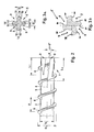
- a thread-cutting screw 1 ( Fig. 1 ) as a concrete screw 2 is used for screwing into a borehole in concrete (not shown).
- the screw 1 has a screw head 3, a screw end 4 and a thread 6 on a screw shaft 5.
- the screw shaft 5 has a portion which is formed without thread 6; in the region of the screw head 3 as a screw shaft 5 without thread 6 and a section on the screw end 4 as a screw shaft 5 with thread 6.
- the screw 1 has a core diameter D i of the screw shaft 5 and an outer diameter D a on the thread 6.
- the thread 6 also has a pitch P, which corresponds to the distance between two turns of the thread 6 ( Fig. 2 ).
- a front portion 7 of the thread-cutting screw 1 starts at the screw end 4 and extends in the direction of a longitudinal axis 8 of the screw 1 in the direction of the screw head 3.
- the front portion 7 comprises approximately two turns of the thread 6.
- four grooves 9 are incorporated ( Fig. 1 to 3 and 5 ).
- the longitudinal grooves 9 have two different lengths L 1 and L 2 in the direction of the longitudinal axis 8.
- Two longitudinal grooves 9 formed with respect to the longitudinal axis 8 have a shorter length L 1 and two longitudinal grooves 9 which are likewise opposite one another with respect to the longitudinal axis 8 have a greater length L 2 (FIG. Fig. 2 ) on.
- the two longitudinal grooves 9 with the length L 1 thereby interrupt only a first turn of the thread 6 and do not reach up to a second turn of the thread 6.
- the longitudinal grooves 9 with the greater length L 2 interrupt both a first and a second turn the thread 6 from the end of the screw 4 and the longitudinal groove 9 with the greater length L 2 terminates at the second turn of the thread 6 and in the second turn of the thread 6, so that of the longitudinal groove 9 with the length L 2 two turns the thread 6 are interrupted ( Fig. 1 and 2 ).
- the screw shaft 5 In a section perpendicular to the longitudinal axis 8 of the screw 1 in the region of the front region 7 of the screw 1, the screw shaft 5 consists of legs 19 oriented essentially perpendicular to one another (FIG. Fig. 3 from). Between these legs 14 of thickness S thus the longitudinal grooves 9 are present.
- the longitudinal grooves 9 are each bounded by two longitudinal sides 10 of the screw shaft 5 and the legs 14.
- the longitudinal groove 9 is substantially L-shaped, because the two longitudinal sides 9 substantially, ie with a deviation of less than 20 ° or 10 °, are aligned perpendicular to each other.
- the longitudinal sides 10 are aligned in the present example at an angle ⁇ of 6 ° to a straight line parallel to the longitudinal axis 8 of the screw 1 ( Fig.
- rock flour can thus be easily transported from a front end portion of the longitudinal groove 9 at the end of the screw 4 in the direction of the screw head 3 in the longitudinal grooves 9, so that less rock flour or no rock flour between the screw shaft 5 and the wall of the bore is present.
- the screw 1 has four equidistant aligned to a circumference of the screw 1 longitudinal grooves 9.
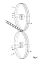
- the preparation or incorporation of these longitudinal grooves 9 is in the Figure 4 and 5 illustrated.
- Two disk-shaped tools 11 have a machining ring 12 at their radial end.
- the disk-shaped tools 11 each rotate about a rotation axis 13 and in the center of the disk-shaped tools 11 on the rotation axis 13 thus forms a center 15 of the tool 11.
- the thread-cutting screw 1 without the longitudinal grooves 9 is available posed.
- the two disc-shaped tools 11 are arranged one above the other, so that the two processing rings 12 each have a distance from each other, and the two axes of rotation 13 of the tools 11 are aligned parallel to each other.
- the screw 1 is placed between the two machining rings 12, so that in each case two opposite pairs of longitudinal grooves 9 are incorporated by a relative movement between the screw 1 and the machining rings 12.
- the angle between the longitudinal axis of the screw 1 and the planes of the tools 11 corresponds to the angle ⁇ of the introduced longitudinal grooves 9.
- a longitudinal groove 9 with a greater length L is formed 2 and at a shorter length of insertion into the space between the processing rings 12, the longitudinal grooves 9 are formed with a smaller length L first
- the depth of the longitudinal grooves 9 decreases starting from the end of the screw 4 in the direction of the screw head 3, because due to the radius R of the circular cross-section screw tool 11, the depth is incorporated correspondingly decreasing ( Fig. 5 ).
- a center 15 of the tool 11 is aligned in a section with a sectional plane through the longitudinal axis 8 at a distance from a plane, wherein the plane rests on the screw end 4 and the plane is also perpendicular to the longitudinal axis 8 perpendicular ( Fig. 5 ).
- the tools 11 have the same radius; However, it is also possible to produce the longitudinal grooves 9 with tools 11 with different radii, in particular with two identical pairs, in which the tools 11 are arranged with the same radius crosswise.
- Fig. 3b is a section perpendicular to the longitudinal axis 8 of the screw 1 shown in the front region, in which the screw 1 was made with such a non-uniform set of tools 11.
- Both in the Fig. 3a and 3b illustrated alternatives have been used tools 11, in which the lateral surface are arranged perpendicular to the side surfaces of the tools 11.
- tools 11 are used in which the lateral surface is arranged at an angle not equal to 90 ° to the side surfaces. This results in longitudinal grooves 9, in which the side surfaces 10 in contrast to those in the Fig. 3a and 3b illustrated alternatives do not include a right angle.
- the thread-cutting screw 1 is associated with significant advantages.
- the thread-cutting screw 1 is simple and inexpensive to manufacture, because the longitudinal grooves 9 can be easily incorporated with at least one disc-shaped tool 11 in the screw 1. Due to the orientation of the longitudinal sides 10 of the longitudinal grooves 9 with respect to the longitudinal axis 8 of the screws 1, when placing and screwing the screw 1 in a borehole in the region of the screw end 4 located rock flour can be easily picked up by the longitudinal grooves 9 and transported in the direction of the screw head 3.
Landscapes
- Engineering & Computer Science (AREA)
- General Engineering & Computer Science (AREA)
- Mechanical Engineering (AREA)
- Physics & Mathematics (AREA)
- Geometry (AREA)
- Processing Of Stones Or Stones Resemblance Materials (AREA)
- Connection Of Plates (AREA)
- Milling Processes (AREA)
- Joining Of Building Structures In Genera (AREA)
Abstract
Description
- Die vorliegende Erfindung betrifft eine gewindeschneidende Schraube gemäß dem Oberbegriff des Anspruches 1 und ein Verfahren zur Herstellung einer gewindeschneidenden Schraube gemäß dem Oberbegriff des Anspruches 9.
- Gewindeschneidende Betonschrauben werden in Bohrlöchern eines Baustoffes, insbesondere Beton, ohne Verwendung eines Dübels eingeschraubt. Dabei ist der Durchmesser des Bohrloches größer als ein Kerndurchmesser der Schraube und kleiner als ein Außendurchmesser der Schraube mit dem Gewinde. Dadurch arbeitet sich beim Einschrauben der Schraube, insbesondere mittels eines Schlagschraubers, die Schraube dahingehend in den Baustoff ein, dass das Gewinde in den Baustoff ein entsprechendes Gegengewinde einarbeitet oder einschneidet. Die Schraube schneidet somit das für den erforderlichen Formschluss zwischen dem Gewinde und dem Baustoff erforderliche Gewinde bzw. Gegengewinde selbst ein.
- Aus der
EP 1 795 768 B1 ist eine gewindeschneidende Schraube, insbesondere Betonschraube, mit einem Gewinde und einem Gewindekern, wobei das Gewinde Schneiden bildende Unterbrechungen aufweist, der Gewindekern in einem vorderen Bereich der Schraube konisch geformt ist und die Schraube eine Nut aufweist, die in einer Längsrichtung der Schraube verläuft, die das Gewinde durchsetzt und die Unterbrechungen bildet und die tiefer als das Gewinde hoch ist, so dass sie in den Gewindekern reicht, wobei die Tiefe der Nut am vorderen Ende der Schraube zum Ende des konischen Bereichs des Gewindekerns abnimmt. - Die Aufgabe der vorliegenden Erfindung besteht darin, eine gewindeschneidende Schraube und ein Verfahren zur Herstellung einer gewindeschneidenden Schraube zur Verfügung zu stellen, bei der das erforderliche Eindrehmoment beim Einschrauben der Schraube in ein Bohrloch gering ist und die Schraube in der Herstellung preiswert ist.
- Diese Aufgabe wird gelöst mit einer gewindeschneidenden Schraube, insbesondere Betonschraube, umfassend einen Schraubenkopf, einen Schraubenschaft und ein wenigstens teilweise an dem Schraubenschaft ausgebildetes Gewinde, wobei an einem vorderen Bereich der Schraube beginnend mit einem Schraubenende an dem Schraubenschaft wenigstens eine Längsnut ausgebildet ist und die wenigstens eine Längsnut von zwei im Wesentlichen, d. h. mit einer Abweichung von weniger als 30°, 20° oder 10° zu einem Radius, radial bezüglich einer Längsachse der Schraube verlaufenden Längsseiten an dem Schraubenschaft begrenzt sind, wobei wenigstens eine Längsseite je Längsnut in einem Winkel α zwischen 1° und 20° zu einer Geraden parallel zu der Längsachse der Schraube ausgerichtet ist und/oder die wenigstens eine Längsnut schraubenlinienförmig an dem Schraubenschaft ausgebildet ist. Der Radius bezüglich der Längsachse steht senkrecht auf der Längsachse. Zweckmäßig ist eine Schraubenlinie der wenigstens einen Längsnut in der gleichen Drehrichtung ausgerichtet wie eine Schraubenlinie des Gewindes. Der Steigungswinkel der Schraubenlinie der wenigstens einen Längsnut liegt zwischen 1 ° und 20°, vorzugsweise zwischen 2° und 10°, insbesondere zwischen 3° und 8°.
- Beim Einschrauben der gewindeschneidenden Schraube in ein Bohrloch tritt im Bereich des Schraubenendes Gesteinsmehl des Baustoffes auf. Das Gesteinsmehl kann dabei daher resultieren, dass dieses entweder nach dem Einbringen der Bohrung in der Bohrung nicht vollständig entfernt wurde und/oder beim Einschrauben der gewindeschneidenden Schraube in das Bohrloch im Bereich des Schraubenendes das Gesteinsmehl entsteht. Die Längsnuten bilden dabei Taschen zur Aufnahme des Gesteinmehles zwischen dem Schraubenschaft und der Wand des Bohrloches. Aufgrund der Ausrichtung wenigstens einer Längsseite der Längsnut in dem Winkel α zu der Geraden wird Gesteinsmehl in den Längsnuten vom Bereich an dem Schraubenende in einen hinteren Bereich in den Längsnuten in Richtung zu dem Schraubenkopf gefördert. Damit kann am vorderen Endbereich der wenigstens einen Längsnut an dem Schraubenende wieder zusätzliches Gesteinsmehl problemlos aufgenommen werden. Dadurch ist weniger Gesteinsmehl oder kein Gesteinsmehl in dem Zwischenraum zwischen dem Schraubenschaft und der Wandung des Bohrloches vorhanden, so dass dadurch die Reibung zwischen der Schraube und der Wandung des Bohrloches verringert werden kann und damit das erforderliche Eindrehmoment wesentlich reduziert ist.
- Insbesondere liegt der Winkel α zwischen 2° und 10°, insbesondere zwischen 3° und 8°.
- In einer weiteren Ausgestaltung sind beide Längsseiten je Längsnut in dem Winkel α zwischen 1° und 20° zu einer Geraden parallel zu der Längsachse der Schraube ausgerichtet.
- In einer ergänzenden Ausführungsform weist die Schraube mehrere, insbesondere äquidistant, über den Umfang verteilte Längsnuten auf. Als besonders vorteilhaft hat sich die Anordnung von vier Längsnuten erwiesen.
- Vorzugsweise weisen die Längsnuten in axialer Richtung eine unterschiedliche Ausdehnung auf.
- In einer Variante ist an der wenigstens einen Längsnut wenigstens ein Gewinde unterbrochen.
- Zweckmäßig ist die wenigstens eine Längsnut im Querschnitt L- oder V-förmig ausgebildet und/oder die Tiefe der wenigstens einen Längsnut nimmt in Richtung von dem Schraubenende zu den Schraubenkopf ab, insbesondere stetig.
- Bevorzugt schleißt mindestens eine Längsseite mindestens einer Längsnut einen rechten Winkel mit dem Schraubenschaft ein, was gleichbedeutend ist, dass diese zumindest eine Längsseite in ihrer radialen Ausrichtung und Verlängerung durch die Schraubenmittelachse verläuft. Hierdurch kann der Schneid- und Transporteffekt der Längsnut weiter optimiert werden.
- In einer weiteren Ausführungsform besteht die Schraube wenigstens teilweise aus Metall, z. B. Stahl, oder, vorzugsweise faserverstärktem Kunststoff, z. B. GFK.
- Erfindungsgemäßes Verfahren zur Herstellung einer gewindeschneidenden Schraube, insbesondere einer in dieser Schutzrechtsanmeldung beschriebenen Schraube, mit den Schritten: zur Verfügung stellen einer gewindeschneidenden Schraube, insbesondere Betonschraube, umfassend einen Schraubenkopf, einen Schraubenschaft und ein wenigstens teilweise an dem Schraubenschaft ausgebildetes Gewinde, Einarbeiten wenigstens einer Längsnut an einen vorderen Bereich der Schraube, wobei wenigstens eine Längsnut in einem Winkel α zwischen 1° und 20° zu einer Geraden parallel zu der Längsachse der Schraube in den Schraubenschaft eingearbeitet wird und/oder wenigstens eine Längsnut schraubenlinienförmig in den Schraubenschaft eingearbeitet wird.
- In einer weiteren Ausgestaltung liegt der Winkel α zwischen 2° und 10°, insbesondere zwischen 3° und 8°.
- Vorteilhafterweise wird die wenigstens eine Längsnut spanabhebend mit einem um eine Rotationsachse rotierenden scheibenförmigen Werkzeug eingearbeitet, wobei die Rotationsachse während des Einarbeitens in dem Winkel α zu einer Geraden ausgerichtet, welche senkrecht zu einer Längsgeraden parallel zu der Längsachse ausgerichtet ist.
- Im Nachfolgenden wird ein Ausführungsbeispiel der Erfindung unter Bezugnahme auf die beigefügten Zeichnungen näher beschrieben. Es zeigen:
- Fig. 1
- eine perspektivische Ansicht einer gewindeschneidenden Schraube,
- Fig. 2
- eine Teilseitenansicht der Schraube gemäß
Fig. 1 , - Fig. 3a, b
- einen Querschnitt der Schraube gemäß
Fig. 1 an einem vorderen Bereich in alternativer Ausgestaltung, - Fig. 4
- eine perspektivische Ansicht zweier scheibenförmiger Werkzeuge und der Schraube während des Einarbeitens von Längsnuten und
- Fig. 5
- eine Seitensicht der Schraube gemäß
Fig. 1 und eines Zentrums des scheibenförmigen Werkzeuges. - Eine gewindeschneidende Schraube 1 (
Fig. 1 ) als Betonschraube 2 dient zum Einschrauben in ein Bohrloch in Beton (nicht dargestellt). Die Schraube 1 weist einen Schraubenkopf 3, ein Schraubenende 4 und ein Gewinde 6 an einem Schraubenschaft 5 auf. Dabei weist der Schraubenschaft 5 einen Abschnitt auf, der ohne Gewinde 6 ausgebildet ist; im Bereich des Schraubenkopfs 3 als Schraubenschaft 5 ohne Gewinde 6 und einen Abschnitt an dem Schraubenende 4 als Schraubenschaft 5 mit Gewinde 6. Die Schraube 1 weist einen Kerndurchmesser Di des Schraubenschaftes 5 sowie einen Außendurchmesser Da am Gewinde 6 auf. Das Gewinde 6 weist ferner eine Steigung P auf, welche dem Abstand zwischen zwei Windungen des Gewindes 6 entspricht (Fig. 2 ). - Ein vorderer Bereich 7 der gewindeschneidenden Schraube 1 beginnt an dem Schraubenende 4 und verläuft dabei in Richtung einer Längsachse 8 der Schraube 1 in Richtung zu dem Schraubenkopf 3. Der vordere Bereich 7 umfasst dabei ungefähr zwei Windungen des Gewindes 6. In dem vorderen Bereich 7 der Schraube 1 sind vier Längsnuten 9 eingearbeitet (
Fig. 1 bis 3 und5 ). Die Längsnuten 9 weisen zwei unterschiedliche Längen L1 und L2 in Richtung der Längsachse 8 auf. Zwei bezüglich der Längsachse 8 ausgebildete Längsnuten 9 weisen eine kürzere Länge L1 auf und zwei ebenfalls bezüglich der Längsachse 8 gegenüberliegende Längsnuten 9 weisen eine größere Länge L2 (Fig. 2 ) auf. Die beiden Längsnuten 9 mit der Länge L1 unterbrechen dabei lediglich nur eine erste Windung des Gewindes 6 und reichen nicht bis zu einer zweiten Windung des Gewindes 6. Die Längsnuten 9 mit der größeren Länge L2 unterbrechen dabei sowohl eine erste als auch eine zweite Windung des Gewindes 6 ab dem Schraubenende 4 und die Längsnut 9 mit der größeren Länge L2 endet dabei an der zweiten Windung des Gewindes 6 bzw. im Bereich der zweiten Windung des Gewindes 6, so dass von der Längsnut 9 mit der Länge L2 zwei Windungen des Gewindes 6 unterbrochen sind (Fig. 1 und2 ). - In einem Schnitt senkrecht zu der Längsachse 8 der Schraube 1 im Bereich des vorderen Bereiches 7 der Schraube 1 besteht der Schraubenschaft 5 aus im Wesentlichen senkrecht zueinander ausgerichteten Schenkeln 14 (
Fig. 3 a,b). Zwischen diesen Schenkeln 14 mit der Dicke S sind somit die Längsnuten 9 vorhanden. Die Längsnuten 9 sind dabei jeweils von zwei Längsseiten 10 des Schraubenschaftes 5 bzw. der Schenkel 14 begrenzt. Die Längsnut 9 ist dabei im Wesentlichen L-förmig ausgebildet, weil die beiden Längsseiten 9 im Wesentlichen, d. h. mit einer Abweichung von weniger als 20° oder 10°, zueinander senkrecht ausgerichtet sind. Die Längsseiten 10 sind im vorliegenden Beispiel in einem Winkel α von 6° zu einer Geraden parallel zu der Längsachse 8 der Schraube 1 ausgerichtet (Fig. 2 ), möglich sind jedoch auch andere Winkel zwischen 1° und 20°. Beim Einschrauben der Schraube 1 in eine nicht dargestellte Bohrung in einem Baustoff entstehendes Gesteinsmehl kann damit leichter von einem vorderen Endbereich der Längsnut 9 an dem Schraubenende 4 in Richtung zu dem Schraubenkopf 3 in den Längsnuten 9 befördert werden, so dass dadurch weniger Gesteinsmehl oder kein Gesteinsmehl zwischen dem Schraubenschaft 5 und der Wandung der Bohrung vorhanden ist. - Die Schraube 1 weist vier äquidistant zu einem Umfang der Schraube 1 ausgerichteten Längsnuten 9 auf. Die Herstellung bzw. das Einarbeiten dieser Längsnuten 9 ist in den
Fig.4 und5 veranschaulicht. Zwei scheibenförmige Werkzeuge 11 weisen an ihrem radialen Ende einen Bearbeitungsring 12 auf. Die scheibenförmigen Werkzeuge 11 rotieren jeweils um eine Rotationsachse 13 und im Zentrum der scheibenförmigen Werkzeuge 11 an der Rotationsachse 13 bildet sich somit ein Zentrum 15 des Werkzeuges 11. Bei der Herstellung der gewindeschneidenden Schraube 1 wird zunächst die gewindeschneidende Schraube 1 ohne die Längsnuten 9 zur Verfügung gestellt. Die beiden scheibenförmigen Werkzeuge 11 sind dabei übereinander angeordnet, so dass die beiden Bearbeitungsringe 12 jeweils einen Abstand zueinander aufweisen, und die beiden Rotationsachsen 13 der Werkzeuge 11 sind zueinander parallel ausgerichtet. Die Schraube 1 wird zwischen den beiden Bearbeitungsringen 12 platziert, so dass durch eine Relativbewegung zwischen Schraube 1 und den Bearbeitungsringen 12 jeweils zwei gegenüberliegende Paare an Längsnuten 9 eingearbeitet werden. Der Winkel zwischen der Längsachse der Schraube 1 und der Ebenen der Werkzeuge 11 entspricht dem Winkel α der eingebrachten Längsnuten 9. Werden die Schrauben 1 in einer größeren Länge in den Raum zwischen den beiden Bearbeitungsringen 12 eingeführt, entsteht eine Längsnut 9 mit einer größeren Länge L2 und bei einer geringeren Länge des Einführens in den Raum zwischen den Bearbeitungsringen 12 entstehen die Längsnuten 9 mit einer kleineren Länge L1. Die Tiefe der Längsnuten 9 nimmt dabei beginnend von dem Schraubenende 4 in Richtung zum Schraubenkopf 3 ab, weil aufgrund des Radius R des im Querschnitt kreisförmigen Schraubenwerkzeuges 11 die Tiefe entsprechend abnehmend eingearbeitet wird (Fig. 5 ). Ein Zentrum 15 des Werkzeuges 11 ist dabei in einem Schnitt mit einer Schnittebene durch die Längsachse 8 in einem Abstand zu einer Ebene ausgerichtet, wobei die Ebene auf dem Schraubenende 4 aufliegt und die Ebene ferner senkrecht auf der Längsachse 8 senkrecht steht (Fig. 5 ). - Im dargestellten Beispiel weisen die Werkzeuge 11 den selben Radius auf; möglich ist jedoch auch die Herstellung der Längsnuten 9 mit Werkzeugen 11 mit verschiedenen Radien, insbesondere mit zwei identischen Paaren, bei denen die Werkzeuge 11 mit dem gleichen Radius über Kreuz angeordnet sind.
- In
Fig. 3b ist ein Schnitt senkrecht zur Längsachse 8 der Schraube 1 im vorderen Bereich dargestellt, bei der die Schraube 1 mit einem derartigen ungleichmäßigen Satz von Werkzeugen 11 hergestellt wurde. - Bei beiden in den
Fig. 3a und 3b dargestellten Alternativen wurden Werkzeuge 11 eingesetzt, bei denen die Mantelfläche senkrecht zu den Seitenflächen der Werkzeuge 11 angeordnet sind. Möglich ist hier alternativ jedoch auch, dass Werkzeuge 11 eingesetzt werden, bei denen die Mantelfläche unter einem Winkel ungleich von 90° zu den Seitenflächen angeordnet ist. Hieraus ergeben sich Längsnuten 9, bei denen die Seitenflächen 10 im Gegensatz zu den in denFig. 3a und 3b dargestellten Alternativen keinen rechten Winkel einschließen. - Insgesamt betrachtet sind mit der gewindeschneidenden Schraube 1 wesentliche Vorteile verbunden. Die gewindeschneidende Schraube 1 ist in der Herstellung einfach und preiswert, weil die Längsnuten 9 einfach mit wenigstens einem scheibenförmigen Werkzeug 11 in die Schraube 1 eingearbeitet werden können. Aufgrund der Ausrichtung der Längsseiten 10 der Längsnuten 9 bezüglich der Längsachse 8 der Schrauben 1 kann beim Einführen und Einschrauben der Schraube 1 in ein Bohrloch im Bereich des Schraubenendes 4 befindliches Gesteinsmehl leicht von den Längsnuten 9 aufgenommen und in Richtung zu dem Schraubenkopf 3 befördert werden.
Claims (14)
- Gewindeschneidende Schraube (1), insbesondere Betonschraube (2), umfassend einen Schraubenkopf (3), einen Schraubenschaft (5) und ein wenigstens teilweise an dem Schraubenschaft (5) ausgebildetes Gewinde (6), wobei an einem vorderen Bereich (7) der Schraube (1) beginnend mit einem Schraubenende (4) an dem Schraubenschaft (5) wenigstens eine Längsnut (9) ausgebildet ist und vorzugsweise die wenigstens eine Längsnut (9) von zwei im Wesentlichen radial bezüglich einer Längsachse (8) der Schraube (1) verlaufenden Längsseiten (10) an dem Schraubenschaft (5) begrenzt sind,
dadurch gekennzeichnet, dass
wenigstens eine Längsseite (10) je Längsnut (9) in einem Winkel α zwischen 1° und 20° zu einer Geraden parallel zu der Längsachse (8) der Schraube (1) ausgerichtet ist
und/oder
die wenigstens eine Längsnut (9) schraubenlinienförmig an dem Schraubenschaft (5) ausgebildet ist. - Schraube nach Anspruch 1,
dadurch gekennzeichnet, dass
der Winkel α zwischen 2° und 10°, insbesondere zwischen 3° und 8°, liegt. - Schraube nach Anspruch 1 oder 2,
dadurch gekennzeichnet, dass
beide Längsseiten (10) je Längsnut (9) in dem Winkel α zwischen 1° und 20° zu einer Geraden parallel zu der Längsachse (8) der Schraube (1) ausgerichtet sind. - Schraube nach einem oder mehreren der vorhergehenden Ansprüche,
dadurch gekennzeichnet, dass
die Schraube (1) mehrere, insbesondere äquidistant, über den Umfang verteilte Längsnuten (9) aufweist. - Schraube nach Anspruch 4,
dadurch gekennzeichnet, dass
die Längsnuten (9) in axialer Richtung eine unterschiedliche Ausdehnung aufweisen. - Schraube nach einem oder mehreren der vorhergehenden Ansprüche,
dadurch gekennzeichnet, dass
an der wenigstens einen Längsnut (9) wenigstens ein Gewinde (6) unterbrochen ist. - Schraube nach einem oder mehreren der vorhergehenden Ansprüche,
dadurch gekennzeichnet, dass
die wenigstens eine Längsnut (9) im Querschnitt L- oder V-förmig ausgebildet ist
und/oder
die Tiefe der wenigstens einen Längsnut (9) in Richtung von dem Schraubenende (4) zu den Schraubenkopf (3), insbesondere stetig, abnimmt. - Schraube nach einem oder mehreren der vorangegangen Ansprüche,
dadurch gekennzeichnet, dass
mindestens eine Längsseite (10) einen rechten Winkel mit dem Schraubenschaft (5) einschließt. - Schraube nach einem oder mehreren der vorhergehenden Ansprüche,
dadurch gekennzeichnet, dass
die Schraube (1) wenigstens teilweise aus Metall, z. B. Stahl, oder, vorzugsweise faserverstärktem Kunststoff, z. B. GFK, besteht - Verfahren zur Herstellung einer gewindeschneidenden Schraube (1), insbesondere einer Schraube (1) nach einem oder mehreren der vorhergehenden Ansprüche, mit den Schritten:- zur Verfügung stellen einer gewindeschneidenden Schraube (1), insbesondere Betonschraube (2), umfassend einen Schraubenkopf (3), einen Schraubenschaft (5) und ein wenigstens teilweise an dem Schraubenschaft (5) ausgebildetes Gewinde (6),- Einarbeiten wenigstens einer Längsnut (9) an einen vorderen Bereich (7) der Schraube (1),dadurch gekennzeichnet, dass
wenigstens eine Längsnut (9) in einem Winkel α zwischen 1° und 20° zu einer Geraden parallel zu der Längsachse (8) der Schraube (1) in den Schraubenschaft (5) eingearbeitet wird
und/oder
wenigstens eine Längsnut (9) schraubenlinienförmig in den Schraubenschaft (5) eingearbeitet wird. - Verfahren nach Anspruch 10,
dadurch gekennzeichnet, dass
der Winkel α zwischen 2° und 10°, insbesondere zwischen 3° und 8°, eingearbeitet wird. - Verfahren nach Anspruch 10 oder 11,
dadurch gekennzeichnet, dass
die wenigstens eine Längsnut (9) spanabhebend mit einem um eine Rotationsachse rotierenden scheibenförmigen Werkzeug (11) eingearbeitet wird und während des Einarbeitens die Rotationsachse (13) in dem Winkel α zu einer Geraden ausgerichtet ist, welche senkrecht zu einer Längsgeraden parallel zu der Längsachse (8) ausgerichtet ist. - Verfahren nach Anspruch 12,
dadurch gekennzeichnet, dass
die Scheiben der rotierenden Werkzeuge (11) unterschiedliche Radien aufweisen - Verfahren nach einem oder mehreren der Ansprüche 10 bis 13,
dadurch gekennzeichnet, dass
alle Längsnuten (9) gleichzeitig in einem Arbeitsschritt erstellt werden.
Priority Applications (1)
| Application Number | Priority Date | Filing Date | Title |
|---|---|---|---|
| PL11162990T PL2386770T3 (pl) | 2010-05-10 | 2011-04-19 | Gwintująca śruba do betonu |
Applications Claiming Priority (1)
| Application Number | Priority Date | Filing Date | Title |
|---|---|---|---|
| DE102010028824A DE102010028824A1 (de) | 2010-05-10 | 2010-05-10 | Gewindeschneidende Betonschraube |
Publications (2)
| Publication Number | Publication Date |
|---|---|
| EP2386770A1 true EP2386770A1 (de) | 2011-11-16 |
| EP2386770B1 EP2386770B1 (de) | 2015-09-23 |
Family
ID=44070591
Family Applications (1)
| Application Number | Title | Priority Date | Filing Date |
|---|---|---|---|
| EP11162990.3A Active EP2386770B1 (de) | 2010-05-10 | 2011-04-19 | Gewindeschneidende Betonschraube |
Country Status (11)
| Country | Link |
|---|---|
| US (1) | US8753056B2 (de) |
| EP (1) | EP2386770B1 (de) |
| JP (1) | JP5752988B2 (de) |
| CN (1) | CN102242754B (de) |
| AU (1) | AU2011202134B2 (de) |
| CA (1) | CA2738182C (de) |
| DE (1) | DE102010028824A1 (de) |
| ES (1) | ES2554664T3 (de) |
| MX (1) | MX2011004616A (de) |
| PL (1) | PL2386770T3 (de) |
| TW (1) | TWI565883B (de) |
Cited By (2)
| Publication number | Priority date | Publication date | Assignee | Title |
|---|---|---|---|---|
| WO2019194920A1 (en) * | 2018-04-06 | 2019-10-10 | Illinois Tool Works Inc. | Self-tapping screw for concrete |
| WO2021023664A1 (de) * | 2019-08-08 | 2021-02-11 | Ludwig Hettich Holding Gmbh & Co. Kg | System zum befestigen eines ankers in einem mineralischen untergrund |
Families Citing this family (14)
| Publication number | Priority date | Publication date | Assignee | Title |
|---|---|---|---|---|
| CN102878175B (zh) * | 2012-10-24 | 2015-05-27 | 长安大学 | 一种自攻自锁木螺栓钉 |
| DE102013203148A1 (de) | 2013-02-26 | 2014-08-28 | Hilti Aktiengesellschaft | Herstellungsverfahren für Schrauben und Betonschraube |
| DE102013203151A1 (de) | 2013-02-26 | 2014-08-28 | Hilti Aktiengesellschaft | Betonschraube |
| DE102013203150A1 (de) | 2013-02-26 | 2014-08-28 | Hilti Aktiengesellschaft | Verfahren zum Herstellen einer Betonschraube |
| US9103364B2 (en) * | 2013-04-19 | 2015-08-11 | Fushang Co., Ltd | Screw |
| SE538636C2 (en) * | 2014-12-12 | 2016-10-04 | Essve Produkter Ab | Concrete screw |
| TWI550197B (zh) * | 2015-03-04 | 2016-09-21 | 林雅侖 | 緊固件 |
| EP3130811A1 (de) * | 2015-08-12 | 2017-02-15 | HILTI Aktiengesellschaft | Verfahren zum setzen einer schraube |
| CN107552696B (zh) * | 2016-07-01 | 2020-07-17 | 常州常宝精特钢管有限公司 | 锥形槽螺纹内模 |
| DE102019104783A1 (de) * | 2019-02-26 | 2020-08-27 | Adolf Würth GmbH & Co. KG | Betonschraube |
| EP3760885A1 (de) * | 2019-07-03 | 2021-01-06 | Hilti Aktiengesellschaft | Einschlagbetonschraube |
| US10889953B1 (en) * | 2020-03-21 | 2021-01-12 | IDIZ Limited | Drill stake and accessories for concrete form construction |
| USD985379S1 (en) * | 2021-03-08 | 2023-05-09 | Schrauben Betzer Gmbh & Co Kg | Screw |
| US11739783B2 (en) | 2021-04-30 | 2023-08-29 | Simpson Strong-Tie Company Inc. | Concrete fastener |
Citations (5)
| Publication number | Priority date | Publication date | Assignee | Title |
|---|---|---|---|---|
| US3780389A (en) * | 1971-10-06 | 1973-12-25 | Elco Industries Inc | Method of manufacturing a self-drilling and self-tapping fastener |
| US5755542A (en) * | 1996-08-06 | 1998-05-26 | Elco Textron, Inc. | Self-drilling/self-tapping fastener |
| US20080124188A1 (en) * | 2006-03-08 | 2008-05-29 | Chang Chen-Chih | Concrete Screws |
| EP1795768B1 (de) | 2005-12-07 | 2008-10-01 | fischerwerke GmbH & Co. KG | Gewindeschneidende Schraube, insbesondere Betonschraube |
| JP2008256093A (ja) * | 2007-04-05 | 2008-10-23 | Koyo Kizai Kk | コンクリート製品類用タッピンねじ |
Family Cites Families (20)
| Publication number | Priority date | Publication date | Assignee | Title |
|---|---|---|---|---|
| FR962890A (de) * | 1947-03-05 | 1950-06-22 | ||
| DE1303320B (de) * | 1962-11-26 | Illinois Tool Works Inc | ||
| US3747143A (en) * | 1971-04-07 | 1973-07-24 | Star Expansion Ind Corp | Screw formation |
| US3789725A (en) * | 1971-10-06 | 1974-02-05 | B Lindstrom | Self-drilling and self-tapping fastener and method of manufacture thereof |
| US3738218A (en) * | 1971-10-06 | 1973-06-12 | Elco Industries Inc | Drilling and thread forming fastener |
| US4147088A (en) * | 1977-03-16 | 1979-04-03 | Nl Industries, Inc. | Drill screw |
| US4241639A (en) * | 1977-11-14 | 1980-12-30 | Illinois Tool Works Inc. | Method and apparatus for producing drill screws |
| JPS59196714U (ja) * | 1983-06-16 | 1984-12-27 | 石渡 晃 | ネジ |
| CH671150A5 (de) * | 1986-10-13 | 1989-08-15 | Jaquet Orthopedie | |
| US4673323A (en) * | 1986-04-07 | 1987-06-16 | Peter Russo | Self tapping stud |
| AU642288B2 (en) * | 1991-04-15 | 1993-10-14 | Wakai & Co., Ltd. | Tapping screw |
| JPH0541623U (ja) * | 1991-11-15 | 1993-06-08 | 株式会社オプテイコン | バーコード用溝切削工具 |
| JPH0752969Y2 (ja) * | 1992-03-04 | 1995-12-06 | 株式会社三橋螺子製作所 | タッピングネジ |
| GB2313167B (en) * | 1996-05-15 | 2000-05-10 | Chen Sen Yang | Screw for fibrous boards |
| JPH1037928A (ja) * | 1996-07-25 | 1998-02-13 | Shoi Rin | ね じ |
| US6106208A (en) * | 1997-12-31 | 2000-08-22 | Lin; Jack | Screw with two cut removing curved grooves |
| JP2002233908A (ja) * | 2001-02-06 | 2002-08-20 | Itabashi Kikai Kogyo Kk | 管継手用管体加工装置 |
| JP4590279B2 (ja) * | 2004-02-12 | 2010-12-01 | トヤマキカイ株式会社 | さらえタップを用いた雌ねじの修復方法 |
| JP2006308079A (ja) * | 2005-03-30 | 2006-11-09 | Sun Wave Ind Co Ltd | 木ねじ |
| EP2419584A1 (de) * | 2009-02-13 | 2012-02-22 | Krinner Innovation GmbH | Bodendübel |
-
2010
- 2010-05-10 DE DE102010028824A patent/DE102010028824A1/de not_active Ceased
-
2011
- 2011-04-07 TW TW100111987A patent/TWI565883B/zh active
- 2011-04-19 ES ES11162990.3T patent/ES2554664T3/es active Active
- 2011-04-19 EP EP11162990.3A patent/EP2386770B1/de active Active
- 2011-04-19 PL PL11162990T patent/PL2386770T3/pl unknown
- 2011-04-27 CA CA2738182A patent/CA2738182C/en active Active
- 2011-05-02 MX MX2011004616A patent/MX2011004616A/es active IP Right Grant
- 2011-05-09 JP JP2011104734A patent/JP5752988B2/ja active Active
- 2011-05-09 CN CN201110117426.1A patent/CN102242754B/zh active Active
- 2011-05-10 US US13/068,377 patent/US8753056B2/en active Active
- 2011-05-10 AU AU2011202134A patent/AU2011202134B2/en active Active
Patent Citations (5)
| Publication number | Priority date | Publication date | Assignee | Title |
|---|---|---|---|---|
| US3780389A (en) * | 1971-10-06 | 1973-12-25 | Elco Industries Inc | Method of manufacturing a self-drilling and self-tapping fastener |
| US5755542A (en) * | 1996-08-06 | 1998-05-26 | Elco Textron, Inc. | Self-drilling/self-tapping fastener |
| EP1795768B1 (de) | 2005-12-07 | 2008-10-01 | fischerwerke GmbH & Co. KG | Gewindeschneidende Schraube, insbesondere Betonschraube |
| US20080124188A1 (en) * | 2006-03-08 | 2008-05-29 | Chang Chen-Chih | Concrete Screws |
| JP2008256093A (ja) * | 2007-04-05 | 2008-10-23 | Koyo Kizai Kk | コンクリート製品類用タッピンねじ |
Cited By (6)
| Publication number | Priority date | Publication date | Assignee | Title |
|---|---|---|---|---|
| WO2019194920A1 (en) * | 2018-04-06 | 2019-10-10 | Illinois Tool Works Inc. | Self-tapping screw for concrete |
| FR3079891A1 (fr) * | 2018-04-06 | 2019-10-11 | Illinois Tool Works Inc | Vis autotaraudeuse a beton |
| WO2021023664A1 (de) * | 2019-08-08 | 2021-02-11 | Ludwig Hettich Holding Gmbh & Co. Kg | System zum befestigen eines ankers in einem mineralischen untergrund |
| US12025167B2 (en) | 2019-08-08 | 2024-07-02 | Ludwig Hettich Holding Gmbh & Co. Kg | System for securing an anchor in a mineral substrate |
| US12049913B2 (en) | 2019-08-08 | 2024-07-30 | Ludwig Hettich Holding Gmbh & Co. Kg | System for securing an anchor in a mineral substrate |
| US12234851B2 (en) | 2019-08-08 | 2025-02-25 | Ludwig Hettich Holding Gmbh & Co. Kg | System for securing an anchor in a mineral substrate |
Also Published As
| Publication number | Publication date |
|---|---|
| MX2011004616A (es) | 2011-11-18 |
| EP2386770B1 (de) | 2015-09-23 |
| US8753056B2 (en) | 2014-06-17 |
| TWI565883B (zh) | 2017-01-11 |
| US20110274516A1 (en) | 2011-11-10 |
| JP2011237034A (ja) | 2011-11-24 |
| AU2011202134A1 (en) | 2011-11-24 |
| PL2386770T3 (pl) | 2016-03-31 |
| CN102242754A (zh) | 2011-11-16 |
| TW201139871A (en) | 2011-11-16 |
| ES2554664T3 (es) | 2015-12-22 |
| DE102010028824A1 (de) | 2011-11-10 |
| CA2738182A1 (en) | 2011-11-10 |
| CN102242754B (zh) | 2015-11-25 |
| AU2011202134B2 (en) | 2013-08-22 |
| CA2738182C (en) | 2017-12-05 |
| JP5752988B2 (ja) | 2015-07-22 |
Similar Documents
| Publication | Publication Date | Title |
|---|---|---|
| EP2386770B1 (de) | Gewindeschneidende Betonschraube | |
| EP2321542B1 (de) | Schraubenantriebsausbildung | |
| EP1936213A2 (de) | Befestigungselement | |
| DE2649766C2 (de) | ||
| DE19545647A1 (de) | Drehschlag-Wendelbohrer | |
| EP2055970A2 (de) | Schraube | |
| EP2476919B1 (de) | Schraubanker und verfahren zur herstellung eines schraubankers | |
| DE102016112357A1 (de) | "Dübelschraube" | |
| EP2266732A1 (de) | Spannsystem | |
| EP3648930B1 (de) | Setzwerkzeug, set für ein setzwerkzeugsystem und setzwerkzeugsystem | |
| EP3219442A1 (de) | Antriebselement zur übertragung eines drehmomentes auf eine gewindeeinsatz-hülse | |
| EP2317159A1 (de) | Schraube insbesondere für zementgebundene Faserplatten | |
| EP3283253B1 (de) | Verbindungselement zur formschlüssigen verbindung mit wenigstens einem bauteil | |
| EP1431511B1 (de) | Gesteinsbohrer | |
| EP3130811A1 (de) | Verfahren zum setzen einer schraube | |
| DE202019004770U1 (de) | Selbstschneidende Einschraubankerhülse | |
| EP3477127B1 (de) | Schraube zum einschrauben in ein bohrloch | |
| EP3135927B1 (de) | Schraube zum einschrauben in ein bohrloch und anordnung mit einer derartigen schraube | |
| DE202016103915U1 (de) | Einschraubdübel | |
| WO2023213816A1 (de) | Stufenbohrer | |
| EP3586015A1 (de) | Schraube | |
| EP3409880B1 (de) | Hybrid-eisbohrer | |
| DE102010041165A1 (de) | Bohrschraube | |
| EP1498618A2 (de) | Schraube für harte Werkstoffe | |
| EP4166799B1 (de) | Verstärkungselement zum verstärken eines werkstoffs sowie eine anordnung mit einem derartigen verstärkungselement in dem werkstoff |
Legal Events
| Date | Code | Title | Description |
|---|---|---|---|
| AK | Designated contracting states |
Kind code of ref document: A1 Designated state(s): AL AT BE BG CH CY CZ DE DK EE ES FI FR GB GR HR HU IE IS IT LI LT LU LV MC MK MT NL NO PL PT RO RS SE SI SK SM TR |
|
| AX | Request for extension of the european patent |
Extension state: BA ME |
|
| PUAI | Public reference made under article 153(3) epc to a published international application that has entered the european phase |
Free format text: ORIGINAL CODE: 0009012 |
|
| 17P | Request for examination filed |
Effective date: 20120516 |
|
| 17Q | First examination report despatched |
Effective date: 20131210 |
|
| GRAP | Despatch of communication of intention to grant a patent |
Free format text: ORIGINAL CODE: EPIDOSNIGR1 |
|
| INTG | Intention to grant announced |
Effective date: 20150511 |
|
| GRAS | Grant fee paid |
Free format text: ORIGINAL CODE: EPIDOSNIGR3 |
|
| GRAA | (expected) grant |
Free format text: ORIGINAL CODE: 0009210 |
|
| AK | Designated contracting states |
Kind code of ref document: B1 Designated state(s): AL AT BE BG CH CY CZ DE DK EE ES FI FR GB GR HR HU IE IS IT LI LT LU LV MC MK MT NL NO PL PT RO RS SE SI SK SM TR |
|
| REG | Reference to a national code |
Ref country code: GB Ref legal event code: FG4D Free format text: NOT ENGLISH |
|
| REG | Reference to a national code |
Ref country code: CH Ref legal event code: EP |
|
| REG | Reference to a national code |
Ref country code: AT Ref legal event code: REF Ref document number: 751421 Country of ref document: AT Kind code of ref document: T Effective date: 20151015 |
|
| REG | Reference to a national code |
Ref country code: IE Ref legal event code: FG4D Free format text: LANGUAGE OF EP DOCUMENT: GERMAN |
|
| REG | Reference to a national code |
Ref country code: DE Ref legal event code: R096 Ref document number: 502011007916 Country of ref document: DE |
|
| REG | Reference to a national code |
Ref country code: ES Ref legal event code: FG2A Ref document number: 2554664 Country of ref document: ES Kind code of ref document: T3 Effective date: 20151222 |
|
| REG | Reference to a national code |
Ref country code: SE Ref legal event code: TRGR |
|
| REG | Reference to a national code |
Ref country code: NL Ref legal event code: MP Effective date: 20150923 |
|
| PG25 | Lapsed in a contracting state [announced via postgrant information from national office to epo] |
Ref country code: LV Free format text: LAPSE BECAUSE OF FAILURE TO SUBMIT A TRANSLATION OF THE DESCRIPTION OR TO PAY THE FEE WITHIN THE PRESCRIBED TIME-LIMIT Effective date: 20150923 Ref country code: GR Free format text: LAPSE BECAUSE OF FAILURE TO SUBMIT A TRANSLATION OF THE DESCRIPTION OR TO PAY THE FEE WITHIN THE PRESCRIBED TIME-LIMIT Effective date: 20151224 Ref country code: NO Free format text: LAPSE BECAUSE OF FAILURE TO SUBMIT A TRANSLATION OF THE DESCRIPTION OR TO PAY THE FEE WITHIN THE PRESCRIBED TIME-LIMIT Effective date: 20151223 Ref country code: LT Free format text: LAPSE BECAUSE OF FAILURE TO SUBMIT A TRANSLATION OF THE DESCRIPTION OR TO PAY THE FEE WITHIN THE PRESCRIBED TIME-LIMIT Effective date: 20150923 |
|
| REG | Reference to a national code |
Ref country code: LT Ref legal event code: MG4D |
|
| PG25 | Lapsed in a contracting state [announced via postgrant information from national office to epo] |
Ref country code: RS Free format text: LAPSE BECAUSE OF FAILURE TO SUBMIT A TRANSLATION OF THE DESCRIPTION OR TO PAY THE FEE WITHIN THE PRESCRIBED TIME-LIMIT Effective date: 20150923 Ref country code: HR Free format text: LAPSE BECAUSE OF FAILURE TO SUBMIT A TRANSLATION OF THE DESCRIPTION OR TO PAY THE FEE WITHIN THE PRESCRIBED TIME-LIMIT Effective date: 20150923 |
|
| REG | Reference to a national code |
Ref country code: FR Ref legal event code: PLFP Year of fee payment: 6 |
|
| PG25 | Lapsed in a contracting state [announced via postgrant information from national office to epo] |
Ref country code: NL Free format text: LAPSE BECAUSE OF FAILURE TO SUBMIT A TRANSLATION OF THE DESCRIPTION OR TO PAY THE FEE WITHIN THE PRESCRIBED TIME-LIMIT Effective date: 20150923 |
|
| PG25 | Lapsed in a contracting state [announced via postgrant information from national office to epo] |
Ref country code: SK Free format text: LAPSE BECAUSE OF FAILURE TO SUBMIT A TRANSLATION OF THE DESCRIPTION OR TO PAY THE FEE WITHIN THE PRESCRIBED TIME-LIMIT Effective date: 20150923 Ref country code: EE Free format text: LAPSE BECAUSE OF FAILURE TO SUBMIT A TRANSLATION OF THE DESCRIPTION OR TO PAY THE FEE WITHIN THE PRESCRIBED TIME-LIMIT Effective date: 20150923 Ref country code: IS Free format text: LAPSE BECAUSE OF FAILURE TO SUBMIT A TRANSLATION OF THE DESCRIPTION OR TO PAY THE FEE WITHIN THE PRESCRIBED TIME-LIMIT Effective date: 20160123 |
|
| PG25 | Lapsed in a contracting state [announced via postgrant information from national office to epo] |
Ref country code: PT Free format text: LAPSE BECAUSE OF FAILURE TO SUBMIT A TRANSLATION OF THE DESCRIPTION OR TO PAY THE FEE WITHIN THE PRESCRIBED TIME-LIMIT Effective date: 20160125 Ref country code: RO Free format text: LAPSE BECAUSE OF FAILURE TO SUBMIT A TRANSLATION OF THE DESCRIPTION OR TO PAY THE FEE WITHIN THE PRESCRIBED TIME-LIMIT Effective date: 20150923 |
|
| REG | Reference to a national code |
Ref country code: DE Ref legal event code: R097 Ref document number: 502011007916 Country of ref document: DE |
|
| PLBE | No opposition filed within time limit |
Free format text: ORIGINAL CODE: 0009261 |
|
| STAA | Information on the status of an ep patent application or granted ep patent |
Free format text: STATUS: NO OPPOSITION FILED WITHIN TIME LIMIT |
|
| 26N | No opposition filed |
Effective date: 20160624 |
|
| PG25 | Lapsed in a contracting state [announced via postgrant information from national office to epo] |
Ref country code: DK Free format text: LAPSE BECAUSE OF FAILURE TO SUBMIT A TRANSLATION OF THE DESCRIPTION OR TO PAY THE FEE WITHIN THE PRESCRIBED TIME-LIMIT Effective date: 20150923 Ref country code: BE Free format text: LAPSE BECAUSE OF NON-PAYMENT OF DUE FEES Effective date: 20160430 |
|
| PG25 | Lapsed in a contracting state [announced via postgrant information from national office to epo] |
Ref country code: SI Free format text: LAPSE BECAUSE OF FAILURE TO SUBMIT A TRANSLATION OF THE DESCRIPTION OR TO PAY THE FEE WITHIN THE PRESCRIBED TIME-LIMIT Effective date: 20150923 |
|
| PG25 | Lapsed in a contracting state [announced via postgrant information from national office to epo] |
Ref country code: LU Free format text: LAPSE BECAUSE OF FAILURE TO SUBMIT A TRANSLATION OF THE DESCRIPTION OR TO PAY THE FEE WITHIN THE PRESCRIBED TIME-LIMIT Effective date: 20160419 |
|
| REG | Reference to a national code |
Ref country code: IE Ref legal event code: MM4A |
|
| REG | Reference to a national code |
Ref country code: FR Ref legal event code: PLFP Year of fee payment: 7 |
|
| PG25 | Lapsed in a contracting state [announced via postgrant information from national office to epo] |
Ref country code: IE Free format text: LAPSE BECAUSE OF NON-PAYMENT OF DUE FEES Effective date: 20160419 |
|
| REG | Reference to a national code |
Ref country code: FR Ref legal event code: PLFP Year of fee payment: 8 |
|
| PG25 | Lapsed in a contracting state [announced via postgrant information from national office to epo] |
Ref country code: CY Free format text: LAPSE BECAUSE OF FAILURE TO SUBMIT A TRANSLATION OF THE DESCRIPTION OR TO PAY THE FEE WITHIN THE PRESCRIBED TIME-LIMIT Effective date: 20150923 Ref country code: HU Free format text: LAPSE BECAUSE OF FAILURE TO SUBMIT A TRANSLATION OF THE DESCRIPTION OR TO PAY THE FEE WITHIN THE PRESCRIBED TIME-LIMIT; INVALID AB INITIO Effective date: 20110419 Ref country code: SM Free format text: LAPSE BECAUSE OF FAILURE TO SUBMIT A TRANSLATION OF THE DESCRIPTION OR TO PAY THE FEE WITHIN THE PRESCRIBED TIME-LIMIT Effective date: 20150923 |
|
| PG25 | Lapsed in a contracting state [announced via postgrant information from national office to epo] |
Ref country code: MT Free format text: LAPSE BECAUSE OF FAILURE TO SUBMIT A TRANSLATION OF THE DESCRIPTION OR TO PAY THE FEE WITHIN THE PRESCRIBED TIME-LIMIT Effective date: 20150923 Ref country code: TR Free format text: LAPSE BECAUSE OF FAILURE TO SUBMIT A TRANSLATION OF THE DESCRIPTION OR TO PAY THE FEE WITHIN THE PRESCRIBED TIME-LIMIT Effective date: 20150923 Ref country code: MC Free format text: LAPSE BECAUSE OF FAILURE TO SUBMIT A TRANSLATION OF THE DESCRIPTION OR TO PAY THE FEE WITHIN THE PRESCRIBED TIME-LIMIT Effective date: 20150923 Ref country code: MK Free format text: LAPSE BECAUSE OF FAILURE TO SUBMIT A TRANSLATION OF THE DESCRIPTION OR TO PAY THE FEE WITHIN THE PRESCRIBED TIME-LIMIT Effective date: 20150923 |
|
| PG25 | Lapsed in a contracting state [announced via postgrant information from national office to epo] |
Ref country code: BG Free format text: LAPSE BECAUSE OF FAILURE TO SUBMIT A TRANSLATION OF THE DESCRIPTION OR TO PAY THE FEE WITHIN THE PRESCRIBED TIME-LIMIT Effective date: 20150923 |
|
| PG25 | Lapsed in a contracting state [announced via postgrant information from national office to epo] |
Ref country code: AL Free format text: LAPSE BECAUSE OF FAILURE TO SUBMIT A TRANSLATION OF THE DESCRIPTION OR TO PAY THE FEE WITHIN THE PRESCRIBED TIME-LIMIT Effective date: 20150923 |
|
| PGFP | Annual fee paid to national office [announced via postgrant information from national office to epo] |
Ref country code: FI Payment date: 20250424 Year of fee payment: 15 |
|
| PGFP | Annual fee paid to national office [announced via postgrant information from national office to epo] |
Ref country code: DE Payment date: 20250422 Year of fee payment: 15 Ref country code: PL Payment date: 20250410 Year of fee payment: 15 |
|
| PGFP | Annual fee paid to national office [announced via postgrant information from national office to epo] |
Ref country code: GB Payment date: 20250423 Year of fee payment: 15 Ref country code: ES Payment date: 20250529 Year of fee payment: 15 |
|
| PGFP | Annual fee paid to national office [announced via postgrant information from national office to epo] |
Ref country code: IT Payment date: 20250424 Year of fee payment: 15 |
|
| PGFP | Annual fee paid to national office [announced via postgrant information from national office to epo] |
Ref country code: FR Payment date: 20250424 Year of fee payment: 15 |
|
| PGFP | Annual fee paid to national office [announced via postgrant information from national office to epo] |
Ref country code: CH Payment date: 20250501 Year of fee payment: 15 |
|
| PGFP | Annual fee paid to national office [announced via postgrant information from national office to epo] |
Ref country code: AT Payment date: 20250423 Year of fee payment: 15 |
|
| PGFP | Annual fee paid to national office [announced via postgrant information from national office to epo] |
Ref country code: CZ Payment date: 20250414 Year of fee payment: 15 |
|
| PGFP | Annual fee paid to national office [announced via postgrant information from national office to epo] |
Ref country code: SE Payment date: 20250429 Year of fee payment: 15 |
|
| REG | Reference to a national code |
Ref country code: CH Ref legal event code: U11 Free format text: ST27 STATUS EVENT CODE: U-0-0-U10-U11 (AS PROVIDED BY THE NATIONAL OFFICE) Effective date: 20260501 |