EP2385455A2 - Dispositif électronique, procédé de transmission d'informations avec un dispositif électronique, procédé de commande d'un dispositif électronique et procédé de transmission et de réception d'informations dans un système informatique - Google Patents
Dispositif électronique, procédé de transmission d'informations avec un dispositif électronique, procédé de commande d'un dispositif électronique et procédé de transmission et de réception d'informations dans un système informatique Download PDFInfo
- Publication number
- EP2385455A2 EP2385455A2 EP11164364A EP11164364A EP2385455A2 EP 2385455 A2 EP2385455 A2 EP 2385455A2 EP 11164364 A EP11164364 A EP 11164364A EP 11164364 A EP11164364 A EP 11164364A EP 2385455 A2 EP2385455 A2 EP 2385455A2
- Authority
- EP
- European Patent Office
- Prior art keywords
- electronic device
- display
- information
- external
- controller
- Prior art date
- Legal status (The legal status is an assumption and is not a legal conclusion. Google has not performed a legal analysis and makes no representation as to the accuracy of the status listed.)
- Granted
Links
- 238000000034 method Methods 0.000 title claims description 139
- 238000004891 communication Methods 0.000 claims abstract description 69
- 230000004044 response Effects 0.000 claims description 11
- 238000013459 approach Methods 0.000 claims description 7
- 238000001514 detection method Methods 0.000 claims description 6
- 230000004913 activation Effects 0.000 claims description 4
- 238000012790 confirmation Methods 0.000 claims 2
- 238000010586 diagram Methods 0.000 description 36
- 230000006870 function Effects 0.000 description 13
- 230000000694 effects Effects 0.000 description 10
- 210000003811 finger Anatomy 0.000 description 9
- 238000010295 mobile communication Methods 0.000 description 8
- 230000005236 sound signal Effects 0.000 description 6
- 238000003860 storage Methods 0.000 description 6
- 230000009471 action Effects 0.000 description 5
- 238000005516 engineering process Methods 0.000 description 4
- 230000008569 process Effects 0.000 description 4
- 230000005540 biological transmission Effects 0.000 description 3
- 230000015572 biosynthetic process Effects 0.000 description 3
- 230000008859 change Effects 0.000 description 3
- 238000011161 development Methods 0.000 description 3
- 230000018109 developmental process Effects 0.000 description 3
- 238000012545 processing Methods 0.000 description 3
- 230000000007 visual effect Effects 0.000 description 3
- 230000008901 benefit Effects 0.000 description 2
- 235000014510 cooky Nutrition 0.000 description 2
- 230000008878 coupling Effects 0.000 description 2
- 238000010168 coupling process Methods 0.000 description 2
- 238000005859 coupling reaction Methods 0.000 description 2
- 238000002347 injection Methods 0.000 description 2
- 239000007924 injection Substances 0.000 description 2
- 238000012905 input function Methods 0.000 description 2
- 239000004973 liquid crystal related substance Substances 0.000 description 2
- 230000007246 mechanism Effects 0.000 description 2
- 230000003287 optical effect Effects 0.000 description 2
- 229910001220 stainless steel Inorganic materials 0.000 description 2
- 239000010935 stainless steel Substances 0.000 description 2
- 230000003068 static effect Effects 0.000 description 2
- 239000010936 titanium Substances 0.000 description 2
- 238000012546 transfer Methods 0.000 description 2
- RTAQQCXQSZGOHL-UHFFFAOYSA-N Titanium Chemical compound [Ti] RTAQQCXQSZGOHL-UHFFFAOYSA-N 0.000 description 1
- 230000001133 acceleration Effects 0.000 description 1
- 238000003491 array Methods 0.000 description 1
- 230000000903 blocking effect Effects 0.000 description 1
- 239000000969 carrier Substances 0.000 description 1
- 238000010276 construction Methods 0.000 description 1
- 238000013500 data storage Methods 0.000 description 1
- 230000009849 deactivation Effects 0.000 description 1
- 230000001419 dependent effect Effects 0.000 description 1
- 230000005684 electric field Effects 0.000 description 1
- 230000005672 electromagnetic field Effects 0.000 description 1
- 239000010408 film Substances 0.000 description 1
- 238000001746 injection moulding Methods 0.000 description 1
- 238000005259 measurement Methods 0.000 description 1
- 239000007769 metal material Substances 0.000 description 1
- 238000012986 modification Methods 0.000 description 1
- 230000004048 modification Effects 0.000 description 1
- 230000003387 muscular Effects 0.000 description 1
- 230000006855 networking Effects 0.000 description 1
- 230000010355 oscillation Effects 0.000 description 1
- 239000000126 substance Substances 0.000 description 1
- 229920003002 synthetic resin Polymers 0.000 description 1
- 239000000057 synthetic resin Substances 0.000 description 1
- 239000010409 thin film Substances 0.000 description 1
- 210000003813 thumb Anatomy 0.000 description 1
- 229910052719 titanium Inorganic materials 0.000 description 1
Images


Classifications
-
- G—PHYSICS
- G06—COMPUTING; CALCULATING OR COUNTING
- G06F—ELECTRIC DIGITAL DATA PROCESSING
- G06F3/00—Input arrangements for transferring data to be processed into a form capable of being handled by the computer; Output arrangements for transferring data from processing unit to output unit, e.g. interface arrangements
- G06F3/01—Input arrangements or combined input and output arrangements for interaction between user and computer
- G06F3/048—Interaction techniques based on graphical user interfaces [GUI]
- G06F3/0481—Interaction techniques based on graphical user interfaces [GUI] based on specific properties of the displayed interaction object or a metaphor-based environment, e.g. interaction with desktop elements like windows or icons, or assisted by a cursor's changing behaviour or appearance
- G06F3/0482—Interaction with lists of selectable items, e.g. menus
-
- G—PHYSICS
- G06—COMPUTING; CALCULATING OR COUNTING
- G06F—ELECTRIC DIGITAL DATA PROCESSING
- G06F3/00—Input arrangements for transferring data to be processed into a form capable of being handled by the computer; Output arrangements for transferring data from processing unit to output unit, e.g. interface arrangements
- G06F3/01—Input arrangements or combined input and output arrangements for interaction between user and computer
- G06F3/048—Interaction techniques based on graphical user interfaces [GUI]
- G06F3/0484—Interaction techniques based on graphical user interfaces [GUI] for the control of specific functions or operations, e.g. selecting or manipulating an object, an image or a displayed text element, setting a parameter value or selecting a range
- G06F3/0486—Drag-and-drop
-
- G—PHYSICS
- G06—COMPUTING; CALCULATING OR COUNTING
- G06F—ELECTRIC DIGITAL DATA PROCESSING
- G06F3/00—Input arrangements for transferring data to be processed into a form capable of being handled by the computer; Output arrangements for transferring data from processing unit to output unit, e.g. interface arrangements
- G06F3/01—Input arrangements or combined input and output arrangements for interaction between user and computer
- G06F3/048—Interaction techniques based on graphical user interfaces [GUI]
- G06F3/0487—Interaction techniques based on graphical user interfaces [GUI] using specific features provided by the input device, e.g. functions controlled by the rotation of a mouse with dual sensing arrangements, or of the nature of the input device, e.g. tap gestures based on pressure sensed by a digitiser
- G06F3/0488—Interaction techniques based on graphical user interfaces [GUI] using specific features provided by the input device, e.g. functions controlled by the rotation of a mouse with dual sensing arrangements, or of the nature of the input device, e.g. tap gestures based on pressure sensed by a digitiser using a touch-screen or digitiser, e.g. input of commands through traced gestures
- G06F3/04886—Interaction techniques based on graphical user interfaces [GUI] using specific features provided by the input device, e.g. functions controlled by the rotation of a mouse with dual sensing arrangements, or of the nature of the input device, e.g. tap gestures based on pressure sensed by a digitiser using a touch-screen or digitiser, e.g. input of commands through traced gestures by partitioning the display area of the touch-screen or the surface of the digitising tablet into independently controllable areas, e.g. virtual keyboards or menus
-
- H—ELECTRICITY
- H04—ELECTRIC COMMUNICATION TECHNIQUE
- H04N—PICTORIAL COMMUNICATION, e.g. TELEVISION
- H04N21/00—Selective content distribution, e.g. interactive television or video on demand [VOD]
- H04N21/40—Client devices specifically adapted for the reception of or interaction with content, e.g. set-top-box [STB]; Operations thereof
- H04N21/41—Structure of client; Structure of client peripherals
- H04N21/422—Input-only peripherals, i.e. input devices connected to specially adapted client devices, e.g. global positioning system [GPS]
- H04N21/42204—User interfaces specially adapted for controlling a client device through a remote control device; Remote control devices therefor
- H04N21/42206—User interfaces specially adapted for controlling a client device through a remote control device; Remote control devices therefor characterized by hardware details
- H04N21/4222—Remote control device emulator integrated into a non-television apparatus, e.g. a PDA, media center or smart toy
-
- H—ELECTRICITY
- H04—ELECTRIC COMMUNICATION TECHNIQUE
- H04N—PICTORIAL COMMUNICATION, e.g. TELEVISION
- H04N21/00—Selective content distribution, e.g. interactive television or video on demand [VOD]
- H04N21/40—Client devices specifically adapted for the reception of or interaction with content, e.g. set-top-box [STB]; Operations thereof
- H04N21/43—Processing of content or additional data, e.g. demultiplexing additional data from a digital video stream; Elementary client operations, e.g. monitoring of home network or synchronising decoder's clock; Client middleware
- H04N21/431—Generation of visual interfaces for content selection or interaction; Content or additional data rendering
- H04N21/4312—Generation of visual interfaces for content selection or interaction; Content or additional data rendering involving specific graphical features, e.g. screen layout, special fonts or colors, blinking icons, highlights or animations
- H04N21/4316—Generation of visual interfaces for content selection or interaction; Content or additional data rendering involving specific graphical features, e.g. screen layout, special fonts or colors, blinking icons, highlights or animations for displaying supplemental content in a region of the screen, e.g. an advertisement in a separate window
-
- H—ELECTRICITY
- H04—ELECTRIC COMMUNICATION TECHNIQUE
- H04N—PICTORIAL COMMUNICATION, e.g. TELEVISION
- H04N21/00—Selective content distribution, e.g. interactive television or video on demand [VOD]
- H04N21/40—Client devices specifically adapted for the reception of or interaction with content, e.g. set-top-box [STB]; Operations thereof
- H04N21/43—Processing of content or additional data, e.g. demultiplexing additional data from a digital video stream; Elementary client operations, e.g. monitoring of home network or synchronising decoder's clock; Client middleware
- H04N21/436—Interfacing a local distribution network, e.g. communicating with another STB or one or more peripheral devices inside the home
- H04N21/4363—Adapting the video stream to a specific local network, e.g. a Bluetooth® network
-
- H—ELECTRICITY
- H04—ELECTRIC COMMUNICATION TECHNIQUE
- H04N—PICTORIAL COMMUNICATION, e.g. TELEVISION
- H04N21/00—Selective content distribution, e.g. interactive television or video on demand [VOD]
- H04N21/40—Client devices specifically adapted for the reception of or interaction with content, e.g. set-top-box [STB]; Operations thereof
- H04N21/43—Processing of content or additional data, e.g. demultiplexing additional data from a digital video stream; Elementary client operations, e.g. monitoring of home network or synchronising decoder's clock; Client middleware
- H04N21/442—Monitoring of processes or resources, e.g. detecting the failure of a recording device, monitoring the downstream bandwidth, the number of times a movie has been viewed, the storage space available from the internal hard disk
- H04N21/44227—Monitoring of local network, e.g. connection or bandwidth variations; Detecting new devices in the local network
-
- H—ELECTRICITY
- H04—ELECTRIC COMMUNICATION TECHNIQUE
- H04N—PICTORIAL COMMUNICATION, e.g. TELEVISION
- H04N21/00—Selective content distribution, e.g. interactive television or video on demand [VOD]
- H04N21/40—Client devices specifically adapted for the reception of or interaction with content, e.g. set-top-box [STB]; Operations thereof
- H04N21/43—Processing of content or additional data, e.g. demultiplexing additional data from a digital video stream; Elementary client operations, e.g. monitoring of home network or synchronising decoder's clock; Client middleware
- H04N21/442—Monitoring of processes or resources, e.g. detecting the failure of a recording device, monitoring the downstream bandwidth, the number of times a movie has been viewed, the storage space available from the internal hard disk
- H04N21/44231—Monitoring of peripheral device or external card, e.g. to detect processing problems in a handheld device or the failure of an external recording device
-
- H—ELECTRICITY
- H04—ELECTRIC COMMUNICATION TECHNIQUE
- H04N—PICTORIAL COMMUNICATION, e.g. TELEVISION
- H04N21/00—Selective content distribution, e.g. interactive television or video on demand [VOD]
- H04N21/40—Client devices specifically adapted for the reception of or interaction with content, e.g. set-top-box [STB]; Operations thereof
- H04N21/45—Management operations performed by the client for facilitating the reception of or the interaction with the content or administrating data related to the end-user or to the client device itself, e.g. learning user preferences for recommending movies, resolving scheduling conflicts
- H04N21/462—Content or additional data management, e.g. creating a master electronic program guide from data received from the Internet and a Head-end, controlling the complexity of a video stream by scaling the resolution or bit-rate based on the client capabilities
- H04N21/4622—Retrieving content or additional data from different sources, e.g. from a broadcast channel and the Internet
-
- H—ELECTRICITY
- H04—ELECTRIC COMMUNICATION TECHNIQUE
- H04N—PICTORIAL COMMUNICATION, e.g. TELEVISION
- H04N21/00—Selective content distribution, e.g. interactive television or video on demand [VOD]
- H04N21/40—Client devices specifically adapted for the reception of or interaction with content, e.g. set-top-box [STB]; Operations thereof
- H04N21/47—End-user applications
- H04N21/478—Supplemental services, e.g. displaying phone caller identification, shopping application
- H04N21/4782—Web browsing, e.g. WebTV
-
- H—ELECTRICITY
- H04—ELECTRIC COMMUNICATION TECHNIQUE
- H04N—PICTORIAL COMMUNICATION, e.g. TELEVISION
- H04N21/00—Selective content distribution, e.g. interactive television or video on demand [VOD]
- H04N21/40—Client devices specifically adapted for the reception of or interaction with content, e.g. set-top-box [STB]; Operations thereof
- H04N21/47—End-user applications
- H04N21/482—End-user interface for program selection
-
- H—ELECTRICITY
- H04—ELECTRIC COMMUNICATION TECHNIQUE
- H04N—PICTORIAL COMMUNICATION, e.g. TELEVISION
- H04N21/00—Selective content distribution, e.g. interactive television or video on demand [VOD]
- H04N21/40—Client devices specifically adapted for the reception of or interaction with content, e.g. set-top-box [STB]; Operations thereof
- H04N21/47—End-user applications
- H04N21/485—End-user interface for client configuration
-
- G—PHYSICS
- G09—EDUCATION; CRYPTOGRAPHY; DISPLAY; ADVERTISING; SEALS
- G09G—ARRANGEMENTS OR CIRCUITS FOR CONTROL OF INDICATING DEVICES USING STATIC MEANS TO PRESENT VARIABLE INFORMATION
- G09G2370/00—Aspects of data communication
- G09G2370/16—Use of wireless transmission of display information
-
- G—PHYSICS
- G09—EDUCATION; CRYPTOGRAPHY; DISPLAY; ADVERTISING; SEALS
- G09G—ARRANGEMENTS OR CIRCUITS FOR CONTROL OF INDICATING DEVICES USING STATIC MEANS TO PRESENT VARIABLE INFORMATION
- G09G5/00—Control arrangements or circuits for visual indicators common to cathode-ray tube indicators and other visual indicators
- G09G5/14—Display of multiple viewports
-
- H—ELECTRICITY
- H04—ELECTRIC COMMUNICATION TECHNIQUE
- H04N—PICTORIAL COMMUNICATION, e.g. TELEVISION
- H04N21/00—Selective content distribution, e.g. interactive television or video on demand [VOD]
- H04N21/40—Client devices specifically adapted for the reception of or interaction with content, e.g. set-top-box [STB]; Operations thereof
- H04N21/47—End-user applications
- H04N21/478—Supplemental services, e.g. displaying phone caller identification, shopping application
- H04N21/4788—Supplemental services, e.g. displaying phone caller identification, shopping application communicating with other users, e.g. chatting
-
- H—ELECTRICITY
- H04—ELECTRIC COMMUNICATION TECHNIQUE
- H04N—PICTORIAL COMMUNICATION, e.g. TELEVISION
- H04N21/00—Selective content distribution, e.g. interactive television or video on demand [VOD]
- H04N21/40—Client devices specifically adapted for the reception of or interaction with content, e.g. set-top-box [STB]; Operations thereof
- H04N21/47—End-user applications
- H04N21/488—Data services, e.g. news ticker
-
- H—ELECTRICITY
- H04—ELECTRIC COMMUNICATION TECHNIQUE
- H04N—PICTORIAL COMMUNICATION, e.g. TELEVISION
- H04N21/00—Selective content distribution, e.g. interactive television or video on demand [VOD]
- H04N21/80—Generation or processing of content or additional data by content creator independently of the distribution process; Content per se
- H04N21/83—Generation or processing of protective or descriptive data associated with content; Content structuring
- H04N21/84—Generation or processing of descriptive data, e.g. content descriptors
- H04N21/8405—Generation or processing of descriptive data, e.g. content descriptors represented by keywords
Definitions
- This invention relates to electronic devices that communicate with each other, an information system including the electronic devices, a method of sending information from at least one of the electronic devices, a method of transmitting and receiving information within an information system, and a method of controlling the electronic devices and the information system.
- a user-friendly user interface (Ul) needs to be provided to electronic devices capable of communicating with other electronic devices.
- Ul user-friendly user interface
- An object of the present invention is to provide devices and methods which overcome the drawbacks of the prior art.
- an electronic device comprises a display unit having a first display area located on a first side of the display unit, a second display area located on a second side of the display unit and a middle display area located between said first and second display areas, a communication unit configured to communicate with at least one external electronic device and a controller configured to control the display unit to display information related to the external electronic device in the first display area, to display an image in the middle display area and to display detailed information related to the image in the second display area.
- an electronic device comprises a communication unit configured to communicate with an external electronic device and a controller configured to receive, via the communication unit, content provided from an external source and information related to said external source from the external electronic device and, and to automatically perform an operation related to the received content in response to the received information.
- an electronic device comprises a communication unit configured to transmit and receive information and a controller configured to receive content from an external source via the communication unit, detect a communication failure while receiving the content, and control the communication unit to transmit information related to the external source to an external electronic device.
- a method for controlling an electronic device comprises the steps of receiving, from an external electronic device via a communication unit, information related to an external source configured to provide content and automatically performing, via a controller, an operation related to the content in response to the received information.
- a method for transmitting information from an electronic device comprises the steps of receiving, via a communication unit, content from an external source via a network, detecting, via a controller, a communication failure while receiving the content, and transmitting, via the communication unit, information related to the external source to an external electronic device upon detection of the communication failure.
- a method for transmitting and receiving information in an information system comprises the steps of transmitting, from a first of the plurality of electronic devices to a second of the plurality of electronic devices, information related to an external source configured for providing content; receiving, via the second of the plurality of electronic devices, the information related to the external source; accessing, via the second of the plurality of electronic devices, the external source in response to the received information; and receiving, via the second of the plurality of electronic devices, the content from the external source.
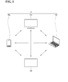
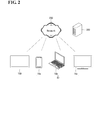
- FIGS. 1 and 2 are schematic diagrams showing system environments to which the invention applies.
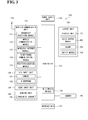
- FIG. 3 is a block diagram of a mobile terminal according to an embodiment of the invention.
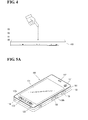
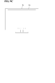
- FIG. 4 is a diagram illustrating the concept of proximity depth of a proximity sensor.
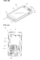
- FIG. 5A is a perspective view showing an example of a front of a portable terminal according to the invention.
- FIG. 5B is a rear perspective view of the portable terminal shown in FIG. 5A .
- FIGS. 6A and 6B are front views of the portable terminal illustrating operating states of the portable terminal according to the invention.
- FIGS. 7 and 8 are diagrams illustrating a graphical user interface (GUI) provided in an electronic device of the invention.
- GUI graphical user interface
- FIGS. 9A to 9C are diagrams showing examples of external electronic devices related to the invention.
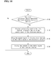
- FIG. 10 is a flowchart illustrating a method of controlling an electronic device according to a first embodiment of the invention.
- FIGS. 11 and 12 are diagrams illustrating the method of controlling an electronic device according to the first embodiment of the invention.
- FIG. 13 is a flowchart illustrating a method of controlling an electronic device according to a second embodiment of the invention.
- FIGS. 14 to 19 are diagrams illustrating the method of controlling an electronic device according to the second embodiment of the invention.
- FIG. 20 is a flowchart illustrating a method of controlling an electronic device according to a third embodiment of the invention.
- FIGS. 21 and 22 are diagrams illustrating the method of controlling an electronic device according to the third embodiment of the invention.
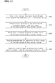
- FIG. 23 is a flowchart illustrating a method of controlling an electronic device according to a fourth embodiment of the invention.
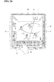
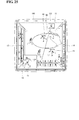
- FIGS. 24 and 25 are diagrams illustrating the method of controlling an electronic device according to the fourth embodiment of the invention.
- FIG. 26 is a flowchart illustrating a method of an electronic device sending information according to a fifth embodiment of the invention.
- FIG. 27 is a diagram illustrating the method of an electronic device sending information according to the fifth embodiment of the invention.
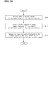
- FIG. 28 is a flowchart illustrating a method of an electronic device sending information according to a sixth embodiment of the invention.
- FIGS. 29A to 29C and 30 are diagrams illustrating the method of an electronic device sending information according to the sixth embodiment of the invention.
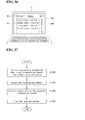
- FIG. 31 is a flowchart illustrating a method of controlling an electronic device according to a seventh embodiment of the invention.
- FIG. 32 is a flowchart illustrating a method of controlling an electronic device according to an eighth embodiment of the invention.
- FIGS. 33 and 34 are diagrams illustrating the method of controlling an electronic device according to the eighth embodiment of the invention.
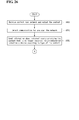
- FIG. 35 is a flowchart illustrating a method of controlling an electronic device according to a ninth embodiment of the invention.
- FIG. 36 is a diagram illustrating the method of controlling an electronic device according to the ninth embodiment of the invention.
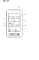
- FIG. 37 is a flowchart illustrating a method of controlling an electronic device according to a tenth embodiment of the invention.
- FIG. 38 is a diagram illustrating the method of controlling an electronic device according to the tenth embodiment of the invention.
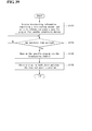
- FIG. 39 is a flowchart illustrating a method of controlling an electronic device according to an eleventh embodiment of the invention.
- FIG. 40 is a diagram showing an example in which a first external electronic device automatically determines an electronic device to which information will be sent.
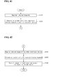
- FIG. 41 is a flowchart illustrating a method of an electronic device sending information according to a twelfth embodiment of the invention.
- FIG. 42 is a flowchart illustrating a method of controlling an electronic device according to a thirteenth embodiment of the invention.
- FIG. 43 is a diagram illustrating the twelfth and thirteenth embodiments of the invention.
- FIGS. 1 and 2 are schematic diagrams showing system environments to which the invention applies.
- the system environment to which the invention applies may include an electronic device 100 according to an embodiment of the invention, external electronic devices 10 separate from the electronic device 100, a network 200, and a server 300 existing on the network 200.
- the external electronic devices 10 may include a first external electronic device 10a, a second external electronic device 10b and a third external electronic device 10c.
- the electronic device 100 and the external electronic devices 10, as shown in FIG. 1 can communicate with each other through a wireless or wired communication method.
- Communication between the electronic device 100 and the external electronic devices 10 is not limited to a specific method. This invention may be applied to all existing wireless communication methods between electronic devices and all future communication methods.
- the electronic device 100 and the external electronic devices 10 can communicate with each other according to known communication methods, such as UPnP® DLNA® and WiFi®. Furthermore, for example, the electronic device 100 and the external electronic devices 10 can communicate with each other via a short-range communication method.
- each of the electronic device 100 and the external electronic devices 10 can communicate over a network 200.
- the electronic device 100 and the external electronic devices 10 can receive multimedia content from a server 300 existing on the network 200.
- the network 200 includes, for example, a mobile communication network, wired Internet, wireless Internet or a broadcasting network.
- the electronic device 100 and the external electronic devices 10 may be fixed terminals or mobile terminals.
- any of the electronic device 100 and the external electronic devices 10 can comprise a portable phone, a smart phone, a personal computer, a laptop computer, a terminal for digital broadcasting, a Personal Digital Assistants (PDA), a Portable Multimedia Player (PMP), a navigator, or a Mobile Internet Device (MID).
- PDA Personal Digital Assistants
- PMP Portable Multimedia Player
- MID Mobile Internet Device
- FIG. 3 is a block diagram of the mobile terminal according to an embodiment of this invention.
- the suffixes 'module' and 'unit' are used for elements in order to facilitate the disclosure only. Therefore, significant meanings or roles are not given to the suffixes themselves and it is understood that the 'module' and 'unit' can be used together or interchangeably.
- the mobile terminal 100 includes a wireless communication unit 110, an audio/video (A/V) input unit 120, a user input unit 130, a sensing unit 140, an output unit 150, a memory 160, an interface unit 170, a controller 180, and a power supply unit 190.
- FIG. 1 shows the mobile terminal 100 having various components, it is understood that implementing all of the illustrated components is not a requirement. More or fewer components may alternatively be implemented.
- the wireless communication unit 110 includes one or more components that permit wireless communication between the mobile terminal 100 and a wireless communication system or a network within which the mobile terminal 100 is located.
- the wireless communication unit 110 includes a broadcast receiving module 111, a mobile communication module 112, a wireless Internet module 113, a short-range communication module 114 and a position-location module 115.
- the wireless communication unit 110 may be replaced with a wired communication unit.
- the wireless communication unit 110 and the wired communication unit may be commonly referred to as a communication unit.
- the broadcast receiving module 111 receives a broadcast signal and/or broadcast associated information from an external broadcast managing entity via a broadcast channel.
- the broadcast channel may include a satellite channel and/or a terrestrial channel.
- the broadcast managing entity may refer to a system that transmits a broadcast signal and/or broadcast associated information.
- the broadcast managing entity may be a server that generates and transmits broadcast signals and/or broadcast associated information or a server for receiving previously generated broadcast signals and/or broadcast-related information and transmitting the broadcast signals and/or the broadcast associated information to the mobile terminal 100.
- the broadcast signals may include not only TV broadcast signals, radio broadcast signals, and data broadcast signals, but also signals in the form of a TV broadcast signal combined with a radio broadcast signal.
- the broadcast associated information may be information about a broadcast channel, a broadcast program, or a broadcast service provider.
- the broadcast associated information may even be provided over a mobile communication network. In the latter case, the broadcast associated information may be received via the mobile communication module 112.
- Examples of broadcast associated information include an electronic program guide (EPG) of digital multimedia broadcasting (DMB) and an electronic service guide (ESG) of digital video broadcast-handheld (DVB-H).
- the broadcast receiving module 111 may receive broadcast signals transmitted from various types of broadcast systems.
- the broadcast systems include digital multimedia broadcasting-terrestrial (DMB-T), digital multimedia broadcasting-satellite (DMB-S), digital video broadcast-handheld (DVB-H), a data broadcasting system known as media forward link only (MediaFLO®) and integrated services digital broadcast-terrestrial (ISDB-T).
- the broadcast receiving module 111 may also receive multicast signals.
- the broadcast signals and/or the broadcast associated information received by the broadcast receiving module 111 may be stored in a suitable storage device, such as in the memory 160.
- the mobile communication module 112 transmits/receives wireless signals to/from at least one of a base station, an external terminal or a server over a mobile communication network.
- the wireless signals may represent, for example, voice call signals, video telephony call signals or data in various forms according to the transmission/reception of text and/or multimedia messages.
- the wireless Internet module 113 supports Internet access for the mobile terminal 100.
- This wireless Internet module 113 may be internally or externally coupled to the mobile terminal 100. Suitable technologies for wireless Internet include, but are not limited to, WLAN (Wireless LAN), Wi-Fi®, Wibro® (Wireless broadband), Wimax® (World Interoperability for Microwave Access), and HSDPA (High Speed Downlink Packet Access).
- the wireless Internet module 113 may be replaced with a wired Internet module in non-mobile terminals.
- the wireless Internet module 113 and the wired Internet module may be commonly referred to as an Internet module.
- the short-range communication module 114 facilitates relatively short-range communications.
- Suitable technologies for short-range communication include, but are not limited to, radio frequency identification (RFID), infrared data association (IrDA), ultra-wideband (UWB), as well as networking technologies such as Bluetooth® and ZigBee®.
- RFID radio frequency identification
- IrDA infrared data association
- UWB ultra-wideband
- networking technologies such as Bluetooth® and ZigBee®.
- the position-location module 115 identifies or otherwise obtains a location of the mobile terminal 100.
- the position-location module 115 may obtain position information by using a global navigation satellite system (GNSS).
- GNSS is a term used to describe radio navigation satellite systems configured to send reference signals capable of determining their positions on the surface of the earth or near the surface of the earth while revolving around the earth.
- the GNSS includes: a global position system (GPS) operated by the U.S.A.; Galileo, operated by Europe; a global orbiting navigational satellite system (GLONASS) operated by Russia; COMPASS, operated by China; and a quasi-zenith satellite system (QZSS) operated by Japan.
- GPS global position system
- Galileo Galileo
- GLONASS global orbiting navigational satellite system
- COMPASS operated by China
- QZSS quasi-zenith satellite system
- the position-location module 115 is a GPS module.
- the position-location module 115 may calculate information related to distances between one point or object and at least three satellites and information related to the time when the distance information was measured and apply trigonometry to the obtained distance information to obtain three-dimensional position information on the point or object according to the latitude, longitude, and altitude at a predetermined time. Furthermore, a method of calculating position and time information using three satellites and correcting the calculated position and time information using another satellite may also used.
- the position-location module 115 continues to calculate a current position in real time and to calculate velocity information based on the position information.
- the audio/video (A/V) input unit 120 may be configured to provide audio or video signal input to the mobile terminal 100.
- the A/V input unit 120 may include a camera 121 and a microphone 122.
- the camera 121 processes image frames of still pictures or video obtained by an image sensor in a photographing mode or a video telephony mode. The processed image frames may be displayed on a display unit 151.
- the image frames processed by the camera 121 may be stored in the memory 160 or transmitted to an external device through the wireless communication unit 110.
- the mobile terminal 100 can include two or more cameras 121, if appropriate.
- the microphone 122 receives an external audio signal while the mobile terminal 100 is in a particular mode, such as a phone call mode, a recording mode and/or a voice recognition mode.
- the received audio signal is processed and converted into digital data.
- the processed digital data is transformed into a format transmittable to a mobile communication base station via the mobile communication module 112 and then output.
- the mobile terminal 100, and in particular the A/V input unit 120 may include a noise removing algorithm to remove noise generated in the course of receiving the external audio signal.
- the user input unit 130 generates input data in response to user manipulation of an associated input device or devices.
- Examples of such devices include a keypad, a dome switch, a touchpad (e.g., static pressure/capacitance), a jog wheel and a jog switch.
- a specific example of the user input unit 130 is a touch screen in which a touchpad is combined with a display, as will be described below.
- the sensing unit 140 provides status measurements of various aspects of the mobile terminal 100.
- the sensing unit 140 may detect an open/closed status of the mobile terminal 100, relative positioning of components (e.g., a display and a keypad) of the mobile terminal 100, a change of position of the mobile terminal 100 or a component of the mobile terminal 100, a presence or absence of user contact with the mobile terminal 100, an orientation of the mobile terminal 100 and/or acceleration/deceleration of the mobile terminal 100.
- components e.g., a display and a keypad
- the mobile terminal 100 may be configured as a slide-type mobile terminal in which the sensing unit 140 may sense whether a sliding portion of the mobile terminal 100 is open or closed.
- the sensing unit 140 may also sense presence or absence of power provided by the power supply unit 190 or the presence or absence of a coupling or other connection between the interface unit 170 and an external device.
- the output unit 150 generates output relevant to the senses of sight, hearing and touch.
- the output unit 150 may include a display unit 151, an audio output module 152, an alarm 153, and a haptic module 154.
- the display unit 151 displays information processed by the mobile terminal 100. For example, when the mobile terminal 100 is in a call mode, the display unit 151 may display a user interface (UI) or a graphic user interface (GUI) associated with the call. If the mobile terminal 100 is in a video communication mode or a photograph mode, the display unit 151 may display a photographed and/or received picture, a UI or a GUI.
- UI user interface
- GUI graphic user interface
- the display unit 151 may include a liquid crystal display (LCD), a thin film transistor liquid crystal display (TFT LCD), an organic light-emitting diode (OLED), a flexible display, or a 3-dimensional display.
- the mobile terminal 100 may include one or more of such displays.
- the display unit 151 may have a transparent or light-transmittive type configuration, hereinafter referred to as a transparent display.
- a transparent OLED (TOLED) is an example of a transparent display.
- a rear configuration of the display unit 151 may also have the light-transmittive type configuration. In this configuration, a user is able to see an object located behind the terminal body via the area occupied by the display unit 151 of the terminal body.
- At least two display units 151 may be provided.
- a plurality of display units 151 may be provided on a single face of the mobile terminal 100 spaced apart from each other or built in one body.
- each of a plurality of display units 151 may be provided on different faces of the mobile terminal 100.
- the display unit 151 and a sensor for detecting a touch action are constructed in a mutual-layered structure (hereafter referred to as a 'touch screen')
- the display unit 151 may be used as an input device and an output device.
- the touch sensor may include a touch film, a touch sheet or a touchpad.
- the touch sensor can be configured to convert a pressure applied to a specific portion of the display unit 151 or a variation of electrostatic capacity generated from a specific portion of the display unit 151 to an electric input signal.
- the touch sensor may detect a pressure of a touch as well as a touched position or magnitude of the touch.
- a touch input is made to the touch sensor, a signal(s) corresponding to the touch input is transferred to a touch controller (not shown).
- the touch controller processes the signal(s) and then transfers corresponding data to the controller 180.
- the controller 180 may determine, therefore, which portion of the display unit 151 is touched.
- a proximity sensor 141 can be provided within the mobile terminal 100 enclosed by the touch screen or around the touch screen.
- the proximity sensor 141 may detect a presence or non-presence of an object approaching a specific detecting surface or an object existing around the proximity sensor 141 using an electromagnetic field strength or infrared ray without mechanical contact. Accordingly, the proximity sensor 141 may have greater durability and greater utility than a contact type sensor.
- the proximity sensor 141 can include a transmittive photoelectric sensor, a direct reflective photoelectric sensor, a mirror reflective photoelectric sensor, a radio frequency oscillation proximity sensor, an electrostatic capacity proximity sensor, a magnetic proximity sensor or an infrared proximity sensor. If the touch screen is an electrostatic type touch screen, the proximity sensor 141 may detect proximity of a pointer using a variation of an electric field according to the proximity of the pointer and the touch screen (touch sensor) may be classified as the proximity sensor 141.
- a 'proximity touch' An action in which a pointer approaches the touch screen without contacting the touch screen, yet is recognized as being located on the touch screen, is referred to as a 'proximity touch'.
- An action in which the pointer actually touches the touch screen is referred to as a 'contact touch'.
- the position on the touch screen proximity-touched by the pointer refers to the position of the pointer that vertically opposes the touch screen when the pointer performs the proximity touch.
- the proximity sensor 141 may detect a proximity touch and/or a proximity touch pattern (e.g., proximity touch distance, proximity touch duration, proximity touch position, proximity touch shift state). Information corresponding to the detected proximity touch action and/or the detected proximity touch pattern may be displayed on the touch screen.
- a proximity touch and/or a proximity touch pattern e.g., proximity touch distance, proximity touch duration, proximity touch position, proximity touch shift state.
- FIG. 4 is a diagram for explaining a proximity depth of the proximity sensor 141. Other embodiments, arrangements and configurations may also be used.
- the proximity sensor 141 ( FIG. 3 ) provided within or in a vicinity of the touch screen detects the approach of the pointer and outputs a proximity signal.
- the proximity sensor 141 can be configured to output a different proximity signal according to a distance between the pointer and the proximity-touched touch screen (hereafter referred to as a proximity depth).
- FIG. 4 shows a cross-section of the touch screen provided with the proximity sensor 141 ( FIG. 3 ) capable of detecting three proximity depths. It is understood that a proximity sensor 141 capable of detecting more or fewer proximity depths is possible.
- the pointer If the pointer fully contacts the touch screen (D0), it is recognized as a contact touch. If the pointer is positioned a distance from the touch screen that is less than (D1) but does not fully contact the touch screen, it is recognized as a proximity touch to a first proximity depth. If the pointer is positioned a distance from the touch screen equal to or greater than (D1) and less than (D2), it is recognized as a proximity touch to a second proximity depth. If the pointer is positioned a distance from the touch screen equal to or greater than (D2) or less than (D3), it is recognized as a proximity touch to a third proximity depth. If the pointer is positioned a distance from the touch screen equal to or greater than (D3), no proximity touch is recognized.
- the controller 180 ( FIG. 3 ) recognizes the proximity touch as one of various input signals according to proximity depth and position of the pointer.
- the controller 180 performs various operation controls according to various input signals.
- the audio output module 152 may output audio data that is received from the wireless communication unit 110 in, for example, a call-receiving mode, a call-placing mode, a recording mode, a voice recognition mode or a broadcast receiving mode.
- the audio output module 152 may output audio data stored in the memory 160.
- the audio output module 152 may output an audio signal relevant to a function (e.g., a call signal receiving sound, a message receiving sound, etc.) performed by the mobile terminal 100.
- the audio output module 152 may include, for example, a receiver, a speaker or a buzzer.
- the alarm 153 outputs a signal for announcing an occurrence of a particular event associated with the mobile terminal 100.
- Typical events include a call signal reception, a message reception, a key signal input and a touch input.
- the alarm 153 outputs a signal for announcing the event occurrence via vibration as well as a video signal or an audio signal.
- the video signal is output via the display unit 151 and the audio signal is output via the audio output module 152.
- the display unit 151 or the audio output module 152 can be regarded as part of the alarm 153.
- the haptic module 154 may generate various haptic effects that can be sensed by a user. Vibration is a representative tactile effect generated by the haptic module 154. Strength and pattern of the vibration generated from the haptic module 154 may be controllable. For example, vibrations differing from each other can be output by being synthesized together or can be output in sequence.
- the haptic module 154 may generate various haptic effects in addition to vibration.
- the haptic module 154 may generate an effect caused by a pin array vertically moving against skin being touched, an air injection force via an injection hole, an air suction force via a suction hole, an effect of skimming on a skin surface, an effect of contact with an electrode, an effect of electrostatic power and/or an effect of a hot/cold sense using an endothermic or exothermic device.
- the haptic module 154 can be configured to provide the haptic effect via direct contact.
- the haptic module 154 can also be configured to enable a user to experience the haptic effect via muscular sense of a finger or an arm.
- Two or more haptic modules 154 can be provided according to a configuration of the mobile terminal 100.
- the memory 160 is configured to store programs for operation of the controller 180.
- the memory 160 may temporarily store input/output data (e.g., phonebook, message, still picture, moving picture, etc.).
- the memory 160 may store data of vibration and sound in various patterns output when the touch screen receives a touch input.
- the memory 160 may include, for example, a flash memory, a hard disk, a multimedia card micro type memory, a card type memory (e.g., SD memory, XD memory, etc.), a random access memory (RAM), a static random access memory (SRAM), a read-only memory (ROM), an electrically erasable programmable read-only memory (EEPROM), a programmable read-only memory(PROM), a magnetic memory, a magnetic disk or an optical disk.
- the mobile terminal 100 may operate in association with a web storage that performs a storage function of the memory 160 via the Internet.
- the interface unit 170 couples the mobile terminal 100 with external devices.
- the interface unit 170 receives data from an external device.
- the interface unit 170 is supplied with power and may be configured to deliver the power to elements within the mobile terminal 100.
- the interface unit 170 may be configured to enable data to be transferred from the mobile terminal 100 to an external device.
- the interface unit 170 may be configured to include a wired/wireless headset port, an external charger port, a wire/wireless data port, a memory card port, a port for coupling to a device having an identity module, an audio input/output (I/O) port, a video input/output (I/O) port or an earphone port.
- the identity module is a chip or card that stores various types of information for authenticating a use authority of the mobile terminal 100 and can include a user identity module (UIM), a subscriber identity module (SIM) and/or a universal subscriber identity module (USIM).
- a device provided with the above identity module (hereafter referred to as an 'identity device') may be manufactured in the form of a smart card.
- the identity device is connectable to the mobile terminal 100 via a corresponding port.
- the interface unit 170 may be configured as a passage for supplying power to the mobile terminal 100 from a cradle that is connected to the mobile terminal 100.
- the interface unit 170 may facilitate delivery of various command signals, which are input via the cradle by a user, to the mobile terminal 100.
- Various command signals input via the cradle or the power may work as a signal for recognizing that the mobile terminal 100 is correctly loaded in the cradle.
- the controller 180 typically controls the overall operations of the mobile terminal 100. For example, the controller 180 performs control and processing associated with voice calls, data communications and video conferences.
- the controller 180 may include a multimedia module 181 that provides multimedia playback.
- the multimedia module 181 may be configured as part of the controller 180 or may be configured as a separate component.
- the controller 180 may also perform pattern recognizing processing for recognizing a handwriting input performed on the touch screen as a character and/or recognizing a picture drawing input performed on the touch screen as characters or images.
- the power supply unit 190 provides power required by the various components for the mobile terminal 100.
- the power may be internal power, external power, or combinations thereof.
- Embodiments of the present invention described in the following description may be implemented within a recording medium that can be read by a computer or a computer-like device using software, hardware or combinations thereof.
- arrangements and embodiments may be implemented using at least one of application specific integrated circuits (ASICs), digital signal processors (DSPs), digital signal processing devices (DSPDs), programmable logic devices (PLDs), field programmable gate arrays (FPGAs), processors, controllers, microcontrollers, microprocessors or electrical units for performing other functions.
- ASICs application specific integrated circuits
- DSPs digital signal processors
- DSPDs digital signal processing devices
- PLDs programmable logic devices
- FPGAs field programmable gate arrays
- processors controllers, microcontrollers, microprocessors or electrical units for performing other functions.
- controller 180 may also be implemented by the controller 180.
- FIG. 5A is a front perspective view showing an example of a front of the mobile terminal 100.
- the mobile terminal 100 of FIG. 5A is depicted as a bar-type terminal body, the mobile terminal 100 may be implemented in a variety of different configurations. Examples of such configurations include a folder-type, a slide-type, a rotational-type, a swing-type and combinations thereof. For clarity, further disclosure will primarily relate to a bar-type mobile terminal 100. However such teachings apply equally to other types of mobile terminals.
- the mobile terminal 100 includes a case (casing, housing, cover, etc.) that forms an exterior thereof.
- the case may be divided into a front case 101 and a rear case 102.
- Various electric/electronic parts are provided in a space between the front case 101 and the rear case 102.
- a middle case may be further provided between the front case 101 and the rear case 102.
- the cases can be formed by injection molding of synthetic resin or may be formed of a metallic material, such as stainless steel (STS) or titanium (Ti).
- the display unit 151, the audio output module 152, the camera 121, user input units 130a and 130b, the microphone 122 and/or the interface unit 170 can be provided on the terminal body, and more particularly on the front case 101.
- the display unit 151 occupies most of a main face of the front case 101.
- the audio output module 152 and the camera 121 may be provided at an area adjacent to one end portion of the display unit 151, while the user input unit 130a and the microphone 122 may be provided at an area adjacent to the other, opposite end portion of the display unit 151.
- the user input unit 130b and the interface unit 170 can be provided on lateral sides of the front and rear cases 101 and 102.
- the user input unit 130 may receive a command for controlling an operation of the mobile terminal 100.
- the user input unit 130 may include a plurality of manipulating units 130a and 130b.
- the manipulating units 130a and 130b can be named a manipulating portion and may adopt any mechanism of a tactile manner that enables a user to perform a manipulation action by experiencing a tactile feeling.
- Content input via the first manipulating unit 130a or the second manipulating unit 130b can be set to be different.
- commands such as start, end and scroll can be input via the first manipulating unit 130a.
- Commands for adjusting volume of sound output from the audio output module 152 and for switching the display unit 151 to a touch recognizing mode can be input via the second manipulating unit 130b.
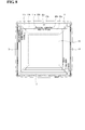
- FIG. 5B is a rear perspective diagram of the mobile terminal 100 shown in FIG. 5A .
- Other embodiments, configurations and arrangements may also be provided.
- an additional camera 121' can be provided on a rear side of the terminal body, and more particularly, on the rear case 102.
- the camera 121' on the rear case 102 has a photographing direction that is substantially opposite to that of the camera 121 shown in FIG. 5A and may have a different resolution.
- the camera 121 may have a smaller number of pixels, and thereby have a relatively lower resolution, to capture and transmit an image of the user's face for a video call, while the camera 121' may have a greater number of pixels, and thereby have a relatively greater resolution, for capturing an image of a general subject for photography without transmitting the captured image.
- Each of the cameras 121 and 121' can be configured to be rotated and/or popped up from the terminal body.
- a flash 123 and a mirror 124 may be disposed adjacent to the camera 121'.
- the flash 123 projects light toward a subject when photographing the subject using the camera 121'.
- the mirror 124 enables the user to view his/her face reflected by the mirror 124.
- An additional audio output module 152' can be disposed at the rear side of the terminal body.
- the additional audio output module 152' facilitates a stereo function in conjunction with the audio output module 152 illustrated in FIG. 5A and may be used for implementation of a speakerphone mode when communicating via the mobile terminal 100.
- a broadcast signal receiving antenna 116 can be provided at a lateral side of the terminal body in addition to an antenna for communication.
- the antenna 116 incorporated into the broadcast receiving module 111 I shown in FIG. 3 can be retractable within the terminal body.
- the power supply unit 190 for supplying a power to the mobile terminal 100 may be provided in the terminal body.
- the power supply unit 190 can be configured to be built within the terminal body or to be detachably connected to the terminal body.
- FIG. 5B also shows a touchpad 135 for detecting a touch input disposed at the rear case 102.
- the touchpad 135 can be a light transmittive type, similar to the display unit 151. If the display unit 151 is configured to output visual information from both its front and rear faces, it recognizes the visual information via the touchpad 135 as well. The information output from the front and rear faces can be entirely controlled by the touchpad 135. Alternatively, a display is provided at the touchpad 135 so that a touch screen can be disposed at the rear case 102.
- the touchpad 135 is activated by interconnecting with the display unit 151 of the front case 101.
- the touchpad 135 can be disposed at the rear of the display unit 151 and in parallel thereto.
- the touchpad 135 can be of a size equal to or smaller than that of the display unit 151.
- FIGS. 6A and 6B are front-view diagrams of a mobile terminal 100 according to one embodiment of the present invention for explaining an operational state thereof.
- the information can be displayed as characters, numerals, symbols, graphics and/or icons.
- FIG. 6A depicts a touch applied to a soft key input through a front face of a terminal body.
- the display unit 151 is operable through an entire area or by being divided into a plurality of regions. In the latter case, a plurality of the regions can be configured to be interoperable.
- an output window 151 a and an input window 151b are displayed on the display unit 151.
- a soft key 151c representing a digit for inputting a phone number or other information is displayed on the input window 151b. If the soft key 151c is touched, a digit corresponding to the touched soft key is displayed on the output window 151a. If a first manipulating unit 130a is manipulated, a call connection for the phone number displayed on the output window 151a is attempted.
- FIG. 6B depicts a touch being applied to a soft key input through a rear face of a terminal body.
- FIG. 6A shows the terminal body arranged vertically (i.e., in a portrait manner), while FIG. 6B shows the terminal body arranged horizontally (i.e., in a landscape manner).
- the display unit 151 can be configured to change an output picture according to the arranged direction of the terminal body.
- FIG. 6B also shows a text input mode activated in the mobile terminal 100.
- FIG. 6B shows the touchpad 135 having an output window 135a and an input window 135b.
- the output window 135a and the input window 135b are visible on the display unit 151.
- a plurality of soft keys 135c representing characters, symbols and/or digits are arranged in the input window 135b.
- the soft keys 135c may be arranged in a QWERTY key formation.
- the soft keys 135c are touched using the touchpad 135, the characters, symbols and/or digits corresponding to the touched soft keys are displayed on the output window 135a.
- the touch input via the touchpad 135 is advantageous in that blocking the soft keys 135c by a finger during a touch can be prevented, as compared to the touch input via the display unit 151. If the display unit 151 and the touchpad 135 are configured as transparent, the user is able to visually see his/her fingers located at the rear side of the terminal body. Hence, more accurate touch inputs are possible.
- the display unit 151 or the touchpad 135 can be configured to receive a touch input by scrolling.
- a user scrolls the display unit 151 or the touchpad 135 to shift a cursor or pointer located at an entity (e.g., an icon) displayed on the display unit 151.
- an entity e.g., an icon
- a path of the shifted finger can be displayed visually on the display unit 151. This may be useful in editing an image displayed on the display unit 151.
- a function of the mobile terminal 100 can be executed.
- the simultaneous touch may occur when the terminal body is held by a user using a thumb and a first finger (clamping).
- the above function can include activation or deactivation for the display unit 151 or the touchpad 135.
- the mobile terminal 100 described with reference to FIGS. 3 to 6 is only an example of the electronic device 100 disclosed by the technical spirit of this invention.
- the electronic device 100 disclosed by the technical spirit of this invention may omit some of the elements of the mobile terminal 100 or may include some elements not included in the mobile terminal 100.
- the display unit 151 of the electronic device 100 is a touch screen 151.
- the touch screen 151 can perform both an information display function and an information input function. It is to be noted, however, that this invention is not limited thereto.
- touch described in this document may include contact touch and proximity touch.
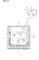
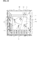
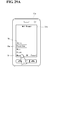
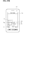
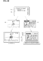
- FIGS. 7 and 8 are diagrams illustrating a graphical user interface (GUI) provided in the electronic device 100.
- GUI graphical user interface
- the controller 180 ( FIG. 3 ) of the electronic device 100 sets at least one region of one or more regions corresponding to a side of a plurality of sides of the touch screen 151 and displays pertinent information in the set region.
- the controller 180 sets a first region 11 (also designated as the first display area 11) corresponding to a first side (e.g., upper side) of the plurality of sides of the touch screen 151, a second region 12 (also designated as the second display area 12) corresponding to a second side (e.g., lower side) of the plurality of sides, a third region 13 (also designated as the third display area 13) corresponding to a third side (e.g., left side) of the plurality of sides, and a fourth region 14 (also designated as the fourth display area 14) corresponding to a fourth side (e.g., right side) of the plurality of sides.
- the controller 180 can also set a middle region 15 (also designated as the middle display area 15) of the touch screen 151.
- the controller 180 ( FIG. 3 ) can set various information to correspond to the first to fourth regions 11, 12, 13, and 14 and the middle region 15.
- the controller 180 set the first region 11 to display information about the at least one external electronic device 10 ( FIG. 1 ). More particularly, the first region 11 displays information related to a plurality of external electronic devices 10 (e.g., mobile phone (first external electronic device 10a), personal computer (second external electronic device 10b) and TV (third external electronic device 10c)) which are currently connected or can be connected.
- the information about the external electronic devices 10a-10c may include identification information to identify the external electronic devices 10a-10c and activation states of the external electronic devices 10a-10c.
- the first region 11 includes a list, including a portion 11a for a first external electronic device 10a, a portion 11b for a second external electronic device 10b, and a portion for a third external electronic device 10c.
- the activation states of the external electronic devices 10a-10c may include information about whether the external electronic devices 10a-10c are currently connected to the electronic device 100, whether the external electronic devices 10a-10c can communicate, and whether the external electronic devices 10a-10c are in an 'on' or an 'off' state.
- the controller 180 FIG. 3
- controls the first to fourth regions 11, 12, 13, and 14 and the middle region 15 of the touch screen 151 to display different information are described later in connection with other embodiments.
- the controller 180 can control the middle region 15 and the first to fourth regions 11, 12, 13, and 14 such that the middle region 15 and the first to fourth regions 11, 12, 13, and 14 are depicted as having different spatial depths.
- the controller 180 may control the touch screen 151 to display the first to fourth regions 11, 12, 13, and 14 such that the spatial depth corresponding to one side of the first to fourth regions 11, 12, 13, and 14 coincides with the spatial depth of the middle region 15 and the spatial depth corresponding to another side of the first to fourth regions 11, 12, 13, and 14, which is opposite to the side of the first to fourth regions that coincides with the spatial depth of the middle region, does not coincide with the spatial depth of the middle region 15.
- one side of the first region 11 that corresponds to the edge of the touch screen 151 and the portion 11 c for the third electronic device 10c is depicted to protrude more than the middle region 15 such that it appears to be closer.
- the opposite side of the first region 11 that corresponds to the portion 11a for the first electronic device 10a and which is adjacent to the middle region 15 is depicted to have the same spatial depth as the middle region 15.
- the controller 180 may control the depiction of the spatial depth of each of the second to fourth regions 12, 13, and 14 in the same manner as the first region 11. Accordingly, the controller 180 can control the first to fourth regions 11, 12, 13, and 14 to appear three dimensional, which causes a user to perceive depth.
- each of the first to fourth regions 11, 12, 13, and 14 and the middle region 15 may always be set and configured to display information.
- the first to fourth regions 11, 12, 13, and 14 and the middle region 15 may be set and configured to display information only as occasions demand, as will be described in subsequent embodiments.
- the mobile terminal 100 described above with reference to FIGS. 3 to 8 is merely an example of the plurality of electronic devices 100 and 10 that may employ the features of the invention.
- Each of the plurality of electronic devices 100 and 10a-10c disclosed may omit some of the elements of the mobile terminal 100 or include additional elements not included in the mobile terminal 100.
- some or all the electronic devices 100 and 10a-10c may include display means, such as display units, having the same function as the display unit 151. Furthermore, some or all electronic devices 100 and 10a-10c including the display means may include a touch screen as the display means.
- the touch screen 151 can perform both the information display function and the information input function. It is to be noted, however, that this invention is not limited thereto. Additionally, 'touch,' as described in this invention, may include contact touch and proximity touch.
- FIGS. 9A to 9C are diagrams showing examples of an external appearance of the first external electronic device 10a, the second external electronic device 10b, and the third external electronic device 10c, respectively.
- the first to third external electronic devices 10a, 10b, and 10c may each include a display unit 51a, 51b, and 51c, respectively.
- an external source refers to an object that can provide content to the plurality of electronic devices 100 and 10a-10c over the network 200 ( FIG. 2 ).
- the external source may include all the subjects existing on the network 200.
- the external source may include a broadcasting station and servers and websites existing on the Internet.
- FIG. 10 is a flowchart illustrating a method of controlling an electronic device according to a first embodiment of this invention.
- FIGS. 11 and 12 are diagrams illustrating the method of controlling an electronic device according to the first embodiment of this invention.
- the method of controlling an electronic device according to the first embodiment of this invention may be implemented in the system environment and the electronic device 100 described with reference to FIGS. 1 to 8 .
- the method of controlling an electronic device according to the first embodiment of this invention and the operations of the electronic device 100 for implementing the method are described in detail below with reference to FIGS. 10-12 .
- the controller 180 determines whether the sensing unit 140 ( FIG. 3 ) detects that the electronic device 100 approached the first external electronic device 10a (step S101). If it is determined that the electronic device 100 has approached the first external electronic device 10a, the controller 180 of the electronic device 100 controls the touch screen 151 of the electronic device 100 to display content displayed in the display means, such as the display unit 51a of the first external electronic device 10a of FIG. 9A , in the second region 12 of the touch screen 151 of the electronic device 100 (step S110).
- Step S110 may be performed in various ways.
- the controller 180 may directly receive the content displayed in the first external electronic device 10a from the first external electronic device 10a.
- the controller 180 may receive the content displayed in the first external electronic device 10a from a different external electronic device, such as the second external electronic device 10b ( FIG. 9B ) or the third external electronic device 10c ( FIG. 9C ), or may receive the content from the server 300 ( FIG. 2 ) over the network 200 ( FIG. 2 ).
- the controller 180 may control the touch screen 151 of the electronic device 100 to display the content displayed in the first external electronic device 10a as appearing slowly from the edge of the second region 12 of the touch screen. In this manner, the content displayed in the first external electronic device 10a appears to be transferred from the display unit 51a of the first external electronic device 10a to the touch screen 151 of the electronic device.
- the content 21 b displayed in the second region 12 of the touch screen 151 is identical to the content 21a displayed in the first external electronic device 10a. While FIG. 11 depicts that content 21a from the first external electronic device 10 is displayed as content 21b in the second region 12 of the touch screen 151, the controller 180 ( FIG. 3 ) may fix the region in which the content 21a from the first external electronic device 10a is displayed to any one of the first to fourth regions 11, 12, 13, and 14 of the touch screen 151 or may vary the region in which the content 21 b is displayed.
- the controller 180 may control the content 21a displayed in the first external electronic device 10a such that the content is displayed in the second region 12 of the touch screen 151.
- the controller 180 may recognize any one of the first to fourth regions 11, 12, 13, and 14 that the first external electronic device 10a approaches, acquire the content displayed in the first external electronic device 10a, and provide the acquired content to the recognized region.
- the controller 180 may control the content 21a displayed in the first external electronic device 10a to be displayed in the fourth region 14 of the touch screen.
- a user may drag the second region 12, or the content 21 b displayed in the second region 12, to the middle region 15 at step S120.
- the controller 180 ( FIG. 3 ) may recognize the drag performed at step S120 and display the content 21b displayed in the second region 12 in the middle region 15 as content 21c at step S130.
- FIG. 12 shows an example of a screen in which the steps S120 and S130 are performed.
- the controller 180 may move the content 21b from the second region 12 of the touch screen 151 to be displayed as content 21c in the middle region 15 of the touch screen 151, in which case the content 21b is no longer displayed in the second region 12 of the touch screen 151, or may copy the content 21b from the second region 12 of the touch screen 151 and display the content 21 c in the middle region 15 of the touch screen 151, in which case the content 21b is displayed in the second region 12 of the touch screen 151 and the content 21 c is displayed in the middle region 15 of the touch screen 151 .
- FIG. 13 is a flowchart illustrating a method of controlling an electronic device according to a second embodiment of this invention.
- FIGS. 14 to 19 are diagrams illustrating the method of controlling an electronic device according to the second embodiment of this invention.
- the method of controlling an electronic device according to the second embodiment of this invention may be implemented in the system environment and the electronic device 100 described with reference to FIGS. 1 to 8 .
- the method of controlling an electronic device according to the second embodiment of this invention and the operations of the electronic device 100 for implementing the method are described in detail below with reference to FIGS. 13-19 .
- the controller 180 ( FIG. 3 ) of the electronic device 100 may receive a selection signal for the third external electronic device 10c ( FIG. 9C ) through the first region 11 of the touch screen 151 at step S200.
- a user may select the third external electronic device 10c by selecting a portion 11c, corresponding to the third external electronic device 10c, in a list displayed in the first region 11 of the touch screen 151, by using a finger, for example.
- FIG. 15 shows an example in which content 23 displayed in the third external electronic device 10c ( FIG. 9C ) is displayed in the first region 11 of the touch screen 151.
- the controller 180 may control the touch screen 151 to display the content 23 displayed in the display unit 51c ( FIG. 9C ) of the third external electronic device 10c in the first region 11 of the touch screen 151 at step S210.
- the controller 180 may receive the content 23 displayed in the third external electronic device 10c directly from the third external electronic device 10c or may receive the content 23 from another external electronic device or from outside the system, such as over the network 200 ( FIG. 2 ), as in the step S110 of FIG. 10 according to the first embodiment of this invention.
- the controller 180 may receive a selection signal for specific content 24 displayed in the middle region 15 of the touch screen 151 at step S220.
- a user may select specific content 24 from among the content items 21 c displayed in the middle region 15 by touching the specific content 24 using a finger, for example.
- the user may drag the selected content 24 to the first region 11 of the touch screen 151 at step S230.
- the controller 180 ( FIG. 3 ) may detect the drag operation performed at step S230 and generate a control signal to display the selected content 24 in the display unit 51c ( FIG. 9C ) of the third external electronic device 10c ( FIG. 9C ) at step S240, as depicted in FIG. 18 .
- Step S240 may be performed in various ways.
- the controller 180 ( FIG. 3 ) of the electronic device 100 may send the selected content 24 directly to the third external electronic device 10c.
- the controller 180 ( FIG. 3 ) of the electronic device 100 may send information about the source of the selected content 24 to the third external electronic device 10c. After receiving the information about the source of the selected content 24, the third external electronic device 10c may receive the content 24 based on the information about the source and display the received content.
- the controller 180 may inform the third external electronic device 10c that the content 24 is stored in the first external electronic device 10a.
- the third external electronic device 10c may request the content 24 from the first external electronic device 10a, receive the content 24 from the first external electronic device 10a, and display the received content.
- FIG. 19 is a diagram showing an example in which additional content 25 is also displayed on the display unit 51c of the third external electronic device 10c according to the execution of step S240.
- a user may select a plurality of content items displayed in the middle region 15 of the touch screen 151 of the electronic device 100 and drag the plurality of content items to the first region 11 of the touch screen 151 of the electronic device 100.
- the plurality of content items can be displayed in the display unit 51c of the external electronic device 10c.
- FIG. 20 is a flowchart illustrating a method of controlling an electronic device according to a third embodiment of this invention.
- FIGS. 21 and 22 are diagrams illustrating the method of controlling an electronic device according to the third embodiment of this invention.
- the method of controlling an electronic device according to the third embodiment of this invention may be implemented in the system environment and the electronic device 100 described with reference to FIGS. 1 to 8 .
- the method of controlling an electronic device according to the third embodiment of this invention and the operations of the electronic device 100 for implementing the method are described in detail below with reference to FIGS. 20-22 .
- the controller 180 ( FIG. 3 ) of the electronic device 100 may display an image in the middle region 15 of the touch screen 151 at step S300.
- the image displayed at step S300 is not limited to a specific source.
- the image displayed in the middle region 15 of the touch screen 151 may be content stored in the memory 160 ( FIG. 3 ) of the electronic device 100, content received through the broadcast receiving module 111 ( FIG. 3 ), content received from the external electronic devices 10a-10c ( FIG. 1 ), or content received from the server 300 ( FIG. 2 ) over the network 200 ( FIG. 2 ).
- the controller 180 may control a list of one or more images depicting different viewpoints of an object.
- the list of one or more images may be displayed in the third region 13 of the touch screen 151.
- At least one of the one or more images depicting the different viewpoints of the object may be related to an image displayed in the middle region 15 of the touch screen 151.
- the electronic device 100 may share broadcast content received by the third external electronic device 10c over a broadcasting network and display the broadcast content in the middle region 15 of the touch screen 151.
- the broadcast content is a soccer game.
- the electronic device 100 may display an image corresponding to a viewpoint seen from a broadcast relay base in the middle region 15 of the touch screen 151.
- the electronic device 100 may also provide a plurality of images corresponding to different viewpoints, such as an image corresponding to a viewpoint seen from the left side of a goalpost and an image corresponding to a viewpoint seen from the right side of the goalpost, in the third region 13 of the touch screen 151.
- FIG. 21 shows an example in which the third external electronic device 10c and the electronic device 100 share broadcast content and output the same broadcast content.
- a first broadcast content 26a is displayed in the third external electronic device 10c and a second broadcast content 26b displayed in the touch screen 151 of the electronic device 100 are the same.
- the controller 180 may receive a selection signal for a specific one of the images displayed in the third region 13 at step S310.
- the controller 180 may replace an image currently displayed in the middle region 15 of the touch screen 151 with the image selected at step S310.
- the third region 13 of the touch screen 151 provides a plurality of images 27 of an object having different viewpoints than the image of the same object displayed in the middle region 15 of the touch screen 151.
- the third region 13 of the touch screen 151 provides a plurality of images depicting different viewpoints of the same content as the content displayed in the middle region 15 of the touch screen 151.
- the controller 180 may control the touch screen to display the selected image 27a in the middle region 15 of the touch screen. Moreover, the controller may control the touch screen 151 to display the image currently displayed in the middle region 15 of the touch screen 151 at the position where the selected image 27a was displayed in the third region 13 of the touch screen, thereby swapping the images.
- FIG. 23 is a flowchart illustrating a method of controlling an electronic device according to a fourth embodiment of this invention.
- FIGS. 24 and 25 are diagrams illustrating the method of controlling an electronic device according to the fourth embodiment of this invention.
- the method of controlling an electronic device according to the fourth embodiment of this invention may be implemented in the system environment and the electronic device 100 described with reference to FIGS. 1 to 8 .
- the method of controlling an electronic device according to the fourth embodiment of this invention and the operations of the electronic device 100 for implementing the method are described in detail below with reference to FIGS. 23-25 .
- the controller 180 ( FIG. 3 ) of the electronic device 100 may control the touch screen 151 to display an image in the middle region 15 of the touch screen 151 at step S400.
- Step S400 is the same as the step S300 according to the third embodiment of this invention illustrated in FIG. 20 .
- the controller 180 may control the touch screen 151 to display, in the second region 12 of the touch screen, detailed information related to the image displayed in the middle region 15 of the touch screen 151.
- FIG. 24 shows an example in which the detailed information related to the image displayed in the middle region 15 is displayed in the second region 12.
- the image displayed in the middle region 15 may be broadcast content related to a soccer game.
- the controller 180 FIG. 3
- the touch screen 151 may display, in the second region 12 of the touch screen, detailed information about players who are now playing the soccer game.
- the image displayed in the middle region 15 of the touch screen 151 may include one or more selectable image objects.
- the players included in the image displayed in the middle region 15 may correspond to the selectable image objects.
- the controller 180 ( FIG. 3 ) may receive a selection signal for a specific one of the one or more selectable image objects of the image at step S410.
- the controller 180 may control the touch screen 151 to display, in the second region 12 of the touch screen, detailed information about the selected image object at step S420.
- FIG. 25 shows an example of a screen performed at steps S410 0 and S420 of FIG. 23 .
- a user may select a specific player 40 included in the image displayed in the middle region 15 of the touch screen 151 or a tag 50, related to the specific player 40, displayed on the touch screen.
- the controller 180 FIG. 3
- the touch screen 151 may display, in the second region 12 of the touch screen, detailed information about the selected player 40 or tag 50.
- FIG. 26 is a flowchart illustrating a method of an electronic device sending information according to a fifth embodiment of this invention.
- FIG. 27 is a diagram illustrating the method of an electronic device sending information according to the fifth embodiment of this invention.
- the method of an electronic device sending information according to the fifth embodiment of this invention may be implemented in each of the plurality of electronic devices 100 and 10a-10c described with reference to FIGS. 1 to 8 .
- the method of an electronic device sending information according to the fifth embodiment of this invention and the operations of the first external electronic device 10a for implementing the method are described in detail on the basis of the first external electronic device 10a for convenience of description.
- the method of an electronic device sending information according to the fifth embodiment of this invention may also be implemented in each of the second external electronic device 10b ( FIG. 9B ), the third external electronic device 10c ( FIG. 9C ), and the electronic device 100 ( FIG. 1 ).
- the first external electronic device 10a may receive content from the network 200 ( FIG. 2 ) and output the received content at step S500.
- the first external electronic device 10a can detect communication failure over the network 200 while receiving and outputting the content at step S510. When communication over the network 200 fails, the first external electronic device 10a no longer receives the content.
- the first external electronic device 10a may send information about an external source providing the content that is no longer received to a predetermined electronic device according to the type of the content being received and output. Step S520 may be automatically performed without a process of confirming a user or may be performed after confirming a user. In performing step S520, the first external electronic device 10a may send a control signal including a command to continue to output the content, together with the information about the external source, to the predetermined electronic device.
- FIG. 27 is a diagram showing an example in which the step S520 is performed after confirming a user.
- the controller of the first external electronic device 10a may control the display unit 51a to display a user interface (UI) 20 for confirming the user.
- the user interface 20 may include information 71 about the type of network 200 ( FIG. 2 ) over which the content is being received, information about the content 17, such as a title 72, and information 73 about the predetermined electronic device.
- the predetermined electronic device may be at least one of the second external electronic device 10b ( FIG. 9B ), the third external electronic device 10c ( FIG. 9C ), and the electronic device 100 ( FIG. 1 ).
- FIG. 9B the second external electronic device 10b
- FIG. 9C the third external electronic device 10c
- the electronic device 100 FIG. 1 .
- the predetermined electronic device is the third external electronic device 10c.
- a user may check a communication failure condition while seeing the information items 71, 72, and 73 provided in the user interface 20 and determine whether to continue to watch the content 17 in the predetermined electronic device by selecting a "Yes" button 74a or a "No” button 74b provided in the user interface 20.
- the first external electronic device 10a may send information about the content 17 to the predetermined electronic device, in addition to the information related to the external source.
- the first external electronic device 10a may send, to the predetermined electronic device, information about a frame of the video at which output was stopped because of the communication failure.
- the predetermined electronic device may receive the information about the frame and play the video from the frame where the output was stopped.
- the first external electronic device 10a may send, to the predetermined electronic device, user information for logging onto a website providing the web page and an access history of the user to the website, such as cookie information. Accordingly, the predetermined electronic device can automatically log onto the website using the user information or the cookie information without an additional login process or without storing information for the login in its storage unit.
- FIG. 28 is a flowchart illustrating a method of an electronic device sending information according to a sixth embodiment of this invention.
- FIGS. 29A to 29C and 30 are diagrams illustrating the method of an electronic device sending information according to the sixth embodiment of this invention.
- the method of an electronic device sending information according to the sixth embodiment of this invention may be implemented in each of the plurality of electronic devices 100 and 10a-10c described with reference to FIGS. 1 to 8 .
- the method of an electronic device sending information according to the sixth embodiment of this invention and the operations of an electronic device for implementing the method are described in detail in relation to the first external electronic device 10a.
- the method of an electronic device sending information according to the sixth embodiment of this invention may also be implemented in each of the second external electronic device 10b ( FIG. 9B ), the third external electronic device 10c ( FIG. 9C ), and the electronic device 100 ( FIG. 1 ).
- the first external electronic device 10a may select one or more content items or one or more external sources corresponding to the one or more content items at step S600. Such selection may be performed automatically or performed by a user according to a predetermined criterion.
- FIGS. 29A and 29B show examples in which a user selects one or more external sources.
- FIG. 29A depicts a web browser that is driven in the first external electronic device 10a.
- the first external electronic device 10a may display a menu window 76 including a plurality of menus.
- the menu window 76 may include a Favorites menu 76a.
- the Favorites menu 76a includes a list of one or more favorite websites ("Favorites list").
- the web browser may manage the Favorites list.
- Memory or an external storage included in the first external electronic device 10a may store information about the one or more websites included in the Favorites list.
- the first external electronic device 10a may provide a sub-menu window 77 including sub-menus regarding the Favorites list.
- the sub-menu window 77 may include at least a 'Send' button 77a and an 'Add' button 77b.
- the first external electronic device 10a selects a list of the websites included in the Favorites list managed by the web browser.
- the first external electronic device 10a may select a predetermined electronic device at step S610 of FIG. 28 .
- step S610 0 may be performed automatically or performed by a user according to a predetermined criterion.
- the predetermined electronic device selected at step S610 may be, for example, one or more of the second external electronic device 10b ( FIG. 9B ), the third external electronic device 10c ( FIG. 9C ), or the electronic device 100 ( FIG. 1 ).
- FIG. 29C depicts an example of a screen displayed in the display unit 51a of the first external electronic device 10a when the 'Send' button 77a is selected in FIG. 29B .
- the screen is used to select one or more electronic device to which the websites in the Favorites list will be sent when the Favorites menu 76a has been selected.
- the screen includes a window 28 that may be used to select the one or more electronic device to which the websites in the Favorites list will be sent
- the window 28 may include check boxes 28a and a list 28b of electronic devices corresponding to each of the check boxes 28a.
- the user may select the one or more electronic device via the check boxes 28a.
- a check box corresponding to 'TV' is selected, as an example.
- the first external electronic device 10a may receive a transmission command at step S620 that instructs that the one or more content items or one or more external sources selected at step S600 be sent to the predetermined electronic device selected at step S610.
- the first external electronic device 10a may send the selected one or more content items or one or more external sources to the selected predetermined electronic device at step S630 in response to the transmission command of step S620.
- the first external electronic device 10a sends the selected Favorites list to the selected TV upon selection of an 'OK' button 29 displayed in the window 28.
- FIG. 30 shows an example of the Favorites list.
- the Favorites list may include information about websites registered by a user or added automatically.
- the Favorites list may include, for example, web addresses 30, IDs 31 and passwords 32 for logging in to specific web sites.
- FIG. 30 shows the Favorites list including information about four websites 30a, 30b, 30c, and 30d.
- FIG. 31 is a flowchart illustrating a method of controlling an electronic device according to a seventh embodiment of this invention.
- the method of controlling the electronic device according to the seventh embodiment of this invention may be implemented in each of the plurality of electronic devices 100 and 10a-10c described with reference to FIGS. 1 to 8 .
- the method of controlling an electronic device according to the seventh embodiment of this invention and the operations of each of the plurality of electronic devices 100 and 10 for implementing the method are described in detail below.
- a specific external electronic device may receive information from an external electronic device about an external source providing content.
- the method of controlling an electronic device according to the seventh embodiment of this invention may be combined and implemented with the fifth or sixth embodiment, or both, of this invention.
- the specific external electronic device may be the second external electronic device 10b ( FIG. 9B ) or the third external electronic device 10c ( FIG. 9C ), or both.
- the specific external electronic device may receive information transmitted by the first external electronic device 10a according to the fifth embodiment or the sixth embodiment of this invention.
- the received information relates to an external source providing content.
- the specific external electronic device may check whether a predetermined operation in relation to the external electronic device or the received information about the external source exists. If the predetermined operation exists, the specific external electronic device may determine whether the predetermined operation has been set up at step S720. If it is determined at step S720 that the predetermined operation has been set up, the specific external electronic device may perform the predetermined operation at step S730. However, if is determined at step S720 that the predetermined operation has not been set up, the specific external electronic device may perform a default operation related to the reception of the content provided by the external source at step S740.
- the second external electronic device 10b ( FIG. 9B ) or the third external electronic device 10c ( FIG. 9C ), or both, may also receive the information about the external source providing the content, together with information about a specific operation related to the content, from the first external electronic device 10a ( FIG. 9A ). In this case, the second external electronic device 10b or the third external electronic device 10c, or both, can perform the specific operation.
- FIG. 32 is a flowchart illustrating a method of controlling an electronic device according to the eighth embodiment of this invention.
- FIGS. 33 and 34 are diagrams illustrating the method of controlling an electronic device according to the eighth embodiment of this invention.
- the method of controlling an electronic device according to the eighth embodiment of this invention may be implemented in each of the plurality of electronic devices 100 and 10a-10c described with reference to FIGS. 1 to 8 .
- the method of controlling an electronic device according to the eighth embodiment of this invention and the operations of the third external electronic device 10c for implementing the method are described in detail.
- the method of controlling an electronic device according to the eighth embodiment of this invention may alternatively be implemented in each of the first external electronic device 10a ( FIG. 9A ), the second external electronic device 10b ( FIG. 9B ), and the electronic device 100 ( FIG. 1 ).
- the third external electronic device 10c may receive a Favorites list including one or more websites from another external electronic device (e.g., 10a or 10b) at step S800.
- An example of step S800 is the third external electronic device 10c receiving the Favorites list described in relation to FIG. 30 from the first external electronic device 10a ( FIG. 9A ) according to the embodiment described with reference to FIGS. 29A to 29C .
- the third external electronic device 10c may access all of the one or more websites included in the received Favorites list at step S810.
- the third external electronic device 10c may display, in the display unit 51 c, a web page provided by each of the accessed websites at the same time at step S820.
- FIGS. 33 and 34 show examples of screens in which the steps S810 and S820 are implemented.
- the third external electronic device 10c may access all websites included in a Favorites list, such as the websites included in the Favorites list shown in FIG. 30 , received from the first external electronic device 10a and display web pages 35a, 35b, 35c, and 35d provided by the websites on the display unit 51c at the same time.
- the third external electronic device 10c may access all websites included in a Favorites list, such as the websites included in the Favorites list shown in FIG. 30 , received from the first external electronic device 10a and display a plurality of tabs 36a, 36b, 36c, and 36d corresponding to web pages provided by each of the websites included in the Favorites list.
- a user may select a specific one of the plurality of tabs 36a, 36b, 36c, and 36d and the controller of the third external electronic device 10c may display, on the display unit 51c, the web page corresponding to the selected tab.
- the third external electronic device 10c may inform the user of such access and update the specific website or not perform any operation.
- FIG. 35 is a flowchart illustrating a method of controlling an electronic device according to the ninth embodiment of this invention.
- FIG. 36 is a diagram illustrating the method of controlling an electronic device according to the ninth embodiment of this invention.
- the method of controlling an electronic device according to the ninth embodiment of this invention may be implemented in each of the plurality of electronic devices 100 and 10a-10c described with reference to FIGS. 1 to 8 .
- the method of controlling an electronic device according to the ninth embodiment of this invention and the operations of the second external electronic device 10b for implementing the method are described in detail.
- the method of controlling an electronic device according to the ninth embodiment of this invention may alternatively be implemented in each of the first external electronic device 10a ( FIG. 9A ), the third external electronic device 10c ( FIG. 9C ), and the electronic device 100 ( FIG. 1 ).
- the second external electronic device 10b may receive information about a website and user entry information related to the website from another electronic device at step S900.
- the second external electronic device 10b may receive, from the first external electronic device 10a ( FIG. 9A ), a web address of a specific website and a search word input by a user for a web search being performed in the specific website.
- the second external electronic device 10b may access the specific website based on the received information about the website at step S910. After accessing the website, the second external electronic device 10b may continue to perform a task that was being performed in the electronic device that sent the information based on the received user entry information at step S920. For example, a web search that was being performed in the electronic device that sent the information may continue to be performed via the accessed website by the second external electronic device 10b by using the received search word.
- FIG. 36 shows an example of a screen in which steps S900 to S920 are implemented.
- the second external electronic device 10b may receive information 40 about a website, such as "Google," and a search word 41, such as "Avatar,” from the first external electronic device 10a ( FIG. 9A ).
- the second external electronic device 10b may continue to perform the web search in the website "Google” by using the search word 41.
- results 42 of the web search using the search word 41 are displayed on the display unit 51 b.
- FIG. 37 is a flowchart illustrating a method of controlling an electronic device according to the tenth embodiment of this invention.
- FIG. 38 is a diagram illustrating the method of controlling an electronic device according to the tenth embodiment of this invention.
- the method of controlling an electronic device according to the tenth embodiment of this invention may be implemented in each of the plurality of electronic devices 100 and 10a-10c described with reference to FIGS. 1 to 8 .
- the method of controlling an electronic device according to the tenth embodiment of this invention and the operations of the third external electronic device 10c for implementing the method are described in detail.
- the method of controlling an electronic device according to the tenth embodiment of this invention may alternatively be implemented in each of the first external electronic device 10a ( FIG. 9A ), the second external electronic device 10b ( FIG. 9B ), and the electronic device 100 ( FIG. 1 ).
- the third external electronic device 10c may receive broadcast information, including a broadcast channel, from another electronic device at step S1010.
- the third external electronic device 10c may access the broadcast channel included in the broadcast information at step S1010 and receive content through the accessed broadcast channel at step S1020.
- the third external electronic device 10c may play the received content at step S1030.
- FIG. 38 shows an example of a screen in which the third external electronic device 10c receives broadcast information including a broadcast channel 45 from the first external electronic device 10a, accesses the broadcast channel 45, receives the content 46 through the broadcast channel 45, and plays the received content 46.
- Video of the received content 46 may be displayed on the display unit 51 c of the third external electronic device 10c.
- FIG. 39 is a flowchart illustrating a method of controlling an electronic device according to the eleventh embodiment of this invention.
- the method of controlling an electronic device according to the eleventh embodiment of this invention may be implemented in each of the plurality of electronic devices 100 and 10a-10c described with reference to FIGS. 1 to 8 .
- the method of controlling an electronic device according to the eleventh embodiment of this invention and the operations of the third external electronic device 10c ( FIG. 9C ) for implementing the method are described in detail.
- the method of controlling an electronic device according to the eleventh embodiment of this invention may alternatively be implemented in each of the first external electronic device 10a ( FIG. 9A ), the second external electronic device 10b ( FIG. 9B ), and the electronic device 100 ( FIG. 1 ).
- the third external electronic device 10c may receive broadcast information, including a broadcast channel and schedule information about a specific program, from another electronic device at step S1100.
- the specific program is provided via the broadcast channel.
- a user may input the schedule information of the specific program in the electronic device and send the broadcast information, including the schedule information, to the third external electronic device 10c ( FIG. 9C ) automatically or manually.
- the schedule information may include information about a detailed operation requested by a user in relation to the specific program.
- the schedule information may include information related to a request for the specific program to be received at the time when the specific program is broadcasted.
- the schedule information may also include information related to a request that the broadcasted program be stored or played, or both stored and played, upon receipt of the broadcasted program.
- the schedule information may include information related to a request that the specific program be received from a specific source at a preset time.
- the specific source may be a specific website that provides the specific program.
- the schedule information may also include information related to a request that the broadcasted program be stored or played, or both stored and played, upon receipt of the broadcasted program.
- the third external electronic device 10c may determine whether a scheduled time included in the schedule information has arrived at step S1110. If it is determined that the scheduled time has arrived, the third external electronic device 10c may receive the specific program via the broadcast channel at step S1120 and store or play, or both store and play, the received specific program at step S1130.
- one program may be received based on the received schedule information and another program may be scheduled to be displayed at the same time.
- the third external electronic device 10c may divide the display unit 51c into two viewing portions and display both of the programs simultaneously.
- the first external electronic device 10a may send information about the one or more external sources to a predetermined electronic device according to a predetermined criterion.
- FIG. 40 is a diagram showing an example in which the first external electronic device 10a automatically determines an electronic device to which information will be sent. For example, at steps S500 and S510 ( FIG. 26 ), when communication over the network 200 ( FIG. 2 ) fails while the first external electronic device 10a receives and outputs the content, another electronic device may be automatically determined as a destination to which information about an external source will be sent based on the content or the information about the external source providing the content.
- the first external electronic device 10a may send information about an external source providing the broadcast program 80 to the third external electronic device 10c.
- the information about the external source may be information related to a broadcast channel.
- the third external electronic device 10c may receive the information about the external source providing the broadcast program 80, receive the broadcast program 80 based on the received information, and display the received broadcast program 80 via the display unit 51 c.
- the first external electronic device 10a may send information about an external source providing the web page 81 to the second external electronic device 10b.
- the information about the external source may be information related to a website providing the web page 81.
- the second external electronic device 10b may receive the information about the external source providing the web page 81 and display the web page 81 on the second display unit 51b b based on the received information.
- FIG. 41 is a flowchart illustrating a method of an electronic device sending information according to a twelfth embodiment of this invention.
- FIG. 42 is a flowchart illustrating a method of controlling an electronic device according to a thirteenth embodiment of this invention.
- FIG. 43 is a diagram illustrating the twelfth and thirteenth embodiments of this invention.
- the method of an electronic device sending information according to the twelfth embodiment of this invention and the method of controlling an electronic device according to the thirteenth embodiment of this invention may be implemented in each of the plurality of electronic devices 100 and 10a-10c described with reference to FIGS. 1 to 8 .
- the method of an electronic device sending information according to the twelfth embodiment of this invention and the operations of the first external electronic device 10a for implementing the method are described in detail.
- the method of controlling an electronic device according to the thirteenth embodiment of this invention and the operations of the second external electronic device 10b and the third external electronic device 10c for implementing the method are described in detail.
- the method of an electronic device sending information according to the twelfth embodiment of this invention and the method of controlling an electronic device according to the thirteenth embodiment of this invention may alternatively be implemented in another electronic device, not described herein, from among the plurality of electronic devices 100 and 10a-10c.
- the first external electronic device 10a may register interest keywords therein at step S1200.
- the first external electronic device 10a may provide various forms of user interfaces for registering the interest keywords.
- FIG. 43(a) depicts an example of a screen in which a user registers interest keywords in the first electronic device 10.
- the user may register the interest keywords by touching keywords 55a, 55b, and 55c that are displayed on the display 51 a.
- the touch performed in FIG. 43(a) is not limited to a specific method, the touch may be performed according to a predetermined method.
- the touch of one of the keywords 55a, 55b 55c is a long touch, such as a touch for more than a predetermined amount of time, the touched keyword may be registered as the interest keyword.
- the touch of one of the keywords 55a, 55b 55c is a multi-touch, such as two touches, the touched keyword may be registered as the interest keyword.
- the interest keyword registered at step S1200 may be stored in an external storage or in a memory included in the first external electronic device 10a.
- the first external electronic device 10a may send the registered interest keyword to another electronic device manually or automatically at step S1210.
- the registered interest keywords can be sent to the second external electronic device 10b or the third external electronic device 10c, or to both the second external electronic device 10b and the third external electronic device 10c.
- specific electronic devices to which the registered interest keywords can be sent are not limited thereto.
- Specific electronic devices to which the registered interest keywords can be sent may be automatically determined according to the type or characteristic of the registered interest keywords. For example, when the registered interest keyword is related to a broadcast, such as the title of a broadcast program that can be received via a broadcast channel, the registered interest keyword may be automatically sent to the third external electronic device 10c, which can access the broadcast channel. In another example, when the registered interest keyword is a common keyword that is not related to a broadcast, the registered interest keyword may be automatically sent to the second external electronic device 10b, which is configured for web search purposes.
- a user may select other electronic devices through a user interface provided in the first external electronic device 10a such that the registered interest keyword is sent to other electronic devices.
- the selected other electronic devices may include the second external electronic device 10b or the third external electronic device 10c, or both the second external electronic device 10b and the third external electronic device 10c.
- the second external electronic device 10b may receive an interest keyword from another electronic device, which in this example is the first external electronic device 10a, at step S1220.
- the second external electronic device 10b may perform a web search using the received interest keyword at step S1230.
- the second external electronic device 10b may store or output, or both store and output, results of the web search at step S1240.
- FIG. 43(b) depicts an example of a screen 57 on the display 51b of the second external electronic device 10b.
- the screen 57 displays results of a web search performed by the second external electronic device 10b using an interest keyword that was sent by the first external electronic device 10a that is depicted in FIG. 43(a) .
- the third external electronic device 10c may also receive the interest keyword from the first external electronic device 10a, as described above.
- the third external electronic device 10c like the second external electronic device 10b, may perform a web search by using the received interest keyword.
- the interest keyword is related to broadcast information, such as the title of a broadcast program
- the third external electronic device 10c may receive a broadcast program corresponding to the interest keyword and play the received broadcast program.
- FIG. 43(c) shows an example of a screen 58 on the display 51c of the third external electronic device 10c.
- the third external electronic device 10c receives a broadcast program corresponding to an interest keyword sent by the first external electronic device 10a of FIG. 43(a) and the screen 58 displays the received broadcast program.
- Programs related to the method of controlling electronic devices, the method of sending information via an electronic device, and the method of transmitting and receiving information via the information system according to the embodiments of this invention may be recorded on a recording medium.
- the programs may be readable by a computer for execution of the programs and then provided to the electronic devices and/or the information system.
- the method of controlling electronic devices, the method of the electronic device sending information, and the method of the information system transmitting and receiving information according to the embodiments of this invention may be executed via software.
- the elements of this invention are code segments that execute necessary tasks.
- the program or code segments may be stored in a processor-readable medium or may be transmitted through a transfer medium or a computer data signal combined with carriers in a communication network.
- the computer-readable recording medium may include all types of recording devices on which data capable of being read by a computer system is recorded.
- the computer-readable recording medium may include ROM, RAM, CD-ROM, DVD-ROM, DVD-RAM, magnetic tapes, floppy disks, hard disks, and optical data storages.
- the computer-readable recording medium may also have its codes, which are distributed into computer apparatuses connected over a network and readable by computers in a distributed manner, stored therein and executed.
- the method of an electronic device sending information, the method of controlling the electronic devices, and the method of the information system transmitting and receiving information according to this invention in a system environment including a plurality of electronic devices that can communicate with each other, information can be efficiently transmitted and received between the plurality of electronic devices, and the plurality of electronic devices can be efficiently controlled.
Landscapes
- Engineering & Computer Science (AREA)
- Multimedia (AREA)
- Signal Processing (AREA)
- General Engineering & Computer Science (AREA)
- Human Computer Interaction (AREA)
- Theoretical Computer Science (AREA)
- Databases & Information Systems (AREA)
- General Physics & Mathematics (AREA)
- Computer Networks & Wireless Communication (AREA)
- Physics & Mathematics (AREA)
- Automation & Control Theory (AREA)
- Business, Economics & Management (AREA)
- Marketing (AREA)
- Telephone Function (AREA)
- User Interface Of Digital Computer (AREA)
- Controls And Circuits For Display Device (AREA)
Applications Claiming Priority (2)
| Application Number | Priority Date | Filing Date | Title |
|---|---|---|---|
| KR1020100041561A KR101781072B1 (ko) | 2010-05-03 | 2010-05-03 | 전자 기기 및 그 제어 방법 |
| KR1020100044836A KR101643260B1 (ko) | 2010-05-13 | 2010-05-13 | 전자 기기 및 그의 제어 방법 |
Publications (3)
| Publication Number | Publication Date |
|---|---|
| EP2385455A2 true EP2385455A2 (fr) | 2011-11-09 |
| EP2385455A3 EP2385455A3 (fr) | 2016-11-09 |
| EP2385455B1 EP2385455B1 (fr) | 2020-04-15 |
Family
ID=44278573
Family Applications (1)
| Application Number | Title | Priority Date | Filing Date |
|---|---|---|---|
| EP11164364.9A Active EP2385455B1 (fr) | 2010-05-03 | 2011-04-29 | Dispositif électronique, procédé de transmission d'informations avec un dispositif électronique, procédé de commande d'un dispositif électronique et procédé de transmission et de réception d'informations dans un système informatique |
Country Status (3)
| Country | Link |
|---|---|
| US (1) | US8966401B2 (fr) |
| EP (1) | EP2385455B1 (fr) |
| CN (1) | CN102238280B (fr) |
Families Citing this family (41)
| Publication number | Priority date | Publication date | Assignee | Title |
|---|---|---|---|---|
| KR101515629B1 (ko) | 2012-01-07 | 2015-04-27 | 삼성전자주식회사 | 플렉서블 표시부를 갖는 휴대단말의 이벤트 제공 방법 및 장치 |
| KR101922023B1 (ko) | 2012-02-20 | 2018-11-26 | 삼성전자주식회사 | 디스플레이장치 및 그 제어방법 |
| US9936329B2 (en) * | 2012-03-09 | 2018-04-03 | Nokia Technologies Oy | Methods, apparatuses, and computer program products for operational routing between proximate devices |
| AU346125S (en) * | 2012-05-29 | 2013-01-04 | Apple Inc | Electronic device |
| USD684571S1 (en) * | 2012-09-07 | 2013-06-18 | Apple Inc. | Electronic device |
| TWI533197B (zh) * | 2012-06-19 | 2016-05-11 | 緯創資通股份有限公司 | 影像輸出方法與電子裝置 |
| US9176703B2 (en) * | 2012-06-29 | 2015-11-03 | Lg Electronics Inc. | Mobile terminal and method of controlling the same for screen capture |
| JP5953984B2 (ja) * | 2012-06-29 | 2016-07-20 | ソニー株式会社 | 通信制御装置、通信制御方法、プログラム、及び通信制御システム |
| KR20140011857A (ko) | 2012-07-20 | 2014-01-29 | 삼성전자주식회사 | 이동 단말에서 디스플레이 장치의 디스플레이를 제어하기 위한 방법 및 이를 위한 이동 단말 |
| CN104364750B (zh) * | 2013-01-06 | 2019-07-16 | 英特尔公司 | 用于触摸数据和显示区域控制的分布式预处理的方法、装置和系统 |
| JP2014216944A (ja) * | 2013-04-26 | 2014-11-17 | 株式会社東芝 | 情報処理装置および表示制御方法 |
| KR102111457B1 (ko) * | 2013-05-15 | 2020-05-15 | 엘지전자 주식회사 | 이동 단말기 및 이동 단말기의 제어 방법 |
| KR101584590B1 (ko) | 2013-07-11 | 2016-01-13 | 삼성전자주식회사 | 어플리케이션을 표시하는 사용자 단말 장치 및 그 방법 |
| US20150067570A1 (en) * | 2013-09-04 | 2015-03-05 | Jae In Yoon | Method and Apparatus for Enhancing User Interface in a Device with Touch Screen |
| US10451874B2 (en) * | 2013-09-25 | 2019-10-22 | Seiko Epson Corporation | Image display device, method of controlling image display device, computer program, and image display system |
| USD766318S1 (en) | 2014-03-07 | 2016-09-13 | Apple Inc. | Display screen or portion thereof with animated graphical user interface |
| KR20150142347A (ko) * | 2014-06-11 | 2015-12-22 | 삼성전자주식회사 | 사용자 단말 및 이의 제어 방법, 그리고 멀티미디어 시스템 |
| KR20160006417A (ko) * | 2014-07-09 | 2016-01-19 | 엘지전자 주식회사 | 이동단말기 및 그 제어방법 |
| KR102358749B1 (ko) * | 2014-12-26 | 2022-02-07 | 엘지전자 주식회사 | 디지털 디바이스 및 그 제어 방법 |
| KR102651726B1 (ko) * | 2016-02-19 | 2024-04-02 | 삼성전자주식회사 | 발광 장치를 포함하는 전자 장치 및, 이의 발광 방법 |
| DE102016202694A1 (de) * | 2016-02-22 | 2017-08-24 | Siemens Aktiengesellschaft | Benutzerschnittstelle mit mehreren Anzeigen und Verfahren zur Positionierung von Inhalten auf mehreren Anzeigen |
| KR102346080B1 (ko) | 2017-03-27 | 2021-12-31 | 삼성전자주식회사 | 터치 스크린을 포함하는 전자 장치와 이의 동작 방법 |
| CN107257248B (zh) * | 2017-07-19 | 2019-10-29 | 泉州泽仕通科技有限公司 | 宽带短波数字电台及其运行方法 |
| WO2019163503A1 (fr) * | 2018-02-22 | 2019-08-29 | 京セラ株式会社 | Dispositif électronique, procédé de commande et programme |
| USD940127S1 (en) | 2018-04-23 | 2022-01-04 | Apple Inc. | Electronic device |
| CN108629820A (zh) * | 2018-04-28 | 2018-10-09 | 维沃移动通信有限公司 | 一种编辑方法及移动终端 |
| US11366571B2 (en) * | 2018-05-04 | 2022-06-21 | Dentma, LLC | Visualization components including sliding bars |
| US11606598B2 (en) * | 2018-09-04 | 2023-03-14 | DraftKings, Inc. | Systems and methods for dynamically adjusting display content and parameters on a display device |
| US11172110B2 (en) | 2019-01-08 | 2021-11-09 | Apple Inc. | Portable electronic device |
| USD976895S1 (en) | 2019-03-15 | 2023-01-31 | Apple Inc. | Electronic device |
| USD945978S1 (en) | 2019-01-08 | 2022-03-15 | Apple Inc. | Electronic device |
| USD945977S1 (en) | 2019-01-08 | 2022-03-15 | Apple Inc. | Electronic device |
| US11616896B2 (en) | 2019-01-08 | 2023-03-28 | Apple Inc. | Portable electronic device |
| USD970460S1 (en) | 2019-03-15 | 2022-11-22 | Apple Inc. | Electronic device |
| USD971170S1 (en) | 2019-09-09 | 2022-11-29 | Apple Inc. | Electronic device |
| USD971171S1 (en) | 2019-09-09 | 2022-11-29 | Apple Inc. | Electronic device |
| USD974352S1 (en) | 2019-11-22 | 2023-01-03 | Apple Inc. | Electronic device |
| USD974353S1 (en) | 2019-11-22 | 2023-01-03 | Apple Inc. | Electronic device |
| USD946018S1 (en) | 2020-06-18 | 2022-03-15 | Apple Inc. | Display screen or portion thereof with graphical user interface |
| USD982006S1 (en) | 2021-04-09 | 2023-03-28 | Apple Inc. | Electronic device |
| USD982005S1 (en) | 2021-04-09 | 2023-03-28 | Apple Inc. | Electronic device |
Family Cites Families (30)
| Publication number | Priority date | Publication date | Assignee | Title |
|---|---|---|---|---|
| US5880733A (en) * | 1996-04-30 | 1999-03-09 | Microsoft Corporation | Display system and method for displaying windows of an operating system to provide a three-dimensional workspace for a computer system |
| US5745109A (en) * | 1996-04-30 | 1998-04-28 | Sony Corporation | Menu display interface with miniature windows corresponding to each page |
| US6002403A (en) * | 1996-04-30 | 1999-12-14 | Sony Corporation | Graphical navigation control for selecting applications on visual walls |
| US6088032A (en) * | 1996-10-04 | 2000-07-11 | Xerox Corporation | Computer controlled display system for displaying a three-dimensional document workspace having a means for prefetching linked documents |
| TW363315B (en) | 1996-11-12 | 1999-07-01 | Toshiba Corp | Communication network system and the rebuilding method |
| US6784925B1 (en) * | 1998-03-24 | 2004-08-31 | Canon Kabushiki Kaisha | System to manage digital camera images |
| US6349410B1 (en) * | 1999-08-04 | 2002-02-19 | Intel Corporation | Integrating broadcast television pause and web browsing |
| US20030046335A1 (en) * | 2001-08-30 | 2003-03-06 | International Business Machines Corporation | Efficiently serving large objects in a distributed computing network |
| US7831992B2 (en) * | 2002-09-18 | 2010-11-09 | General Instrument Corporation | Method and apparatus for forwarding television channel video image snapshots to an auxiliary display device |
| US20030188322A1 (en) * | 2002-03-28 | 2003-10-02 | General Instrument Corporation | Method and system for remotely displaying television program content using streaming video |
| US20060031889A1 (en) * | 2002-12-11 | 2006-02-09 | Bennett James D | Video processing system with simultaneous multiple outputs each with unique formats |
| JP3972836B2 (ja) * | 2003-02-27 | 2007-09-05 | ソニー株式会社 | 表示画面共有システム,送信側端末装置,プログラム,表示画面共有方法 |
| GB0313866D0 (en) * | 2003-06-14 | 2003-07-23 | Impressive Ideas Ltd | Display system for recorded media |
| JP4193629B2 (ja) * | 2003-07-25 | 2008-12-10 | ソニー株式会社 | 画面表示装置,プログラム,および画面表示方法 |
| US10152190B2 (en) * | 2003-12-15 | 2018-12-11 | Open Invention Network, Llc | Systems and methods for improved application sharing in a multimedia collaboration session |
| US7460134B2 (en) * | 2004-03-02 | 2008-12-02 | Microsoft Corporation | System and method for moving computer displayable content into a preferred user interactive focus area |
| US8260933B2 (en) * | 2006-02-15 | 2012-09-04 | Samsung Electronics Co., Ltd. | Multimedia content redirection method |
| US7880728B2 (en) * | 2006-06-29 | 2011-02-01 | Microsoft Corporation | Application switching via a touch screen interface |
| CN101035057B (zh) | 2007-03-30 | 2011-03-30 | 华为技术有限公司 | 建立组播共享树的方法和数据传送的方法、通信网络 |
| US20080295012A1 (en) * | 2007-05-23 | 2008-11-27 | Microsoft Corporation | Drag-and-drop abstraction |
| US8213977B2 (en) | 2007-06-15 | 2012-07-03 | Alcatel Lucent | Method and apparatus for presenting and controlling information for managing an event |
| KR101442544B1 (ko) | 2007-12-18 | 2014-09-23 | 엘지전자 주식회사 | 이동 단말기 및 그의 무선기기 표시 방법 |
| KR20090120722A (ko) | 2008-05-20 | 2009-11-25 | 엘지전자 주식회사 | 이동 단말기 및 이것의 콘텐츠 다운로드 방법 |
| US8850052B2 (en) * | 2008-09-30 | 2014-09-30 | Apple Inc. | System and method for simplified resource sharing |
| KR20100109686A (ko) * | 2009-04-01 | 2010-10-11 | 삼성전자주식회사 | Gui 제공방법 및 이를 적용한 멀티미디어 기기 |
| US8914462B2 (en) * | 2009-04-14 | 2014-12-16 | Lg Electronics Inc. | Terminal and controlling method thereof |
| WO2011019155A2 (fr) * | 2009-08-14 | 2011-02-17 | Lg Electronics Inc. | Télécommande et procédé afférent |
| US20110088068A1 (en) * | 2009-10-09 | 2011-04-14 | Sony Ericsson Mobile Communications Ab | Live media stream selection on a mobile device |
| US8572303B2 (en) * | 2010-02-03 | 2013-10-29 | Tal Lavian | Portable universal communication device |
| US8819726B2 (en) * | 2010-10-14 | 2014-08-26 | Cyandia, Inc. | Methods, apparatus, and systems for presenting television programming and related information |
-
2011
- 2011-04-22 US US13/092,863 patent/US8966401B2/en not_active Expired - Fee Related
- 2011-04-29 EP EP11164364.9A patent/EP2385455B1/fr active Active
- 2011-04-29 CN CN201110114882.0A patent/CN102238280B/zh not_active Expired - Fee Related
Non-Patent Citations (1)
| Title |
|---|
| None |
Also Published As
| Publication number | Publication date |
|---|---|
| EP2385455A3 (fr) | 2016-11-09 |
| US8966401B2 (en) | 2015-02-24 |
| CN102238280B (zh) | 2015-04-01 |
| EP2385455B1 (fr) | 2020-04-15 |
| CN102238280A (zh) | 2011-11-09 |
| US20110268218A1 (en) | 2011-11-03 |
Similar Documents
| Publication | Publication Date | Title |
|---|---|---|
| EP2385455B1 (fr) | Dispositif électronique, procédé de transmission d'informations avec un dispositif électronique, procédé de commande d'un dispositif électronique et procédé de transmission et de réception d'informations dans un système informatique | |
| US9081477B2 (en) | Electronic device and method of controlling the same | |
| US8766934B2 (en) | Method for displaying a menu in mobile terminal and mobile terminal thereof | |
| EP2290927B1 (fr) | Terminal mobile et procédé de contrôle d'une image de prévisualisation d'appareil photographique | |
| KR101836403B1 (ko) | 디스플레이 장치의 리모콘 기능을 수행하는 이동 단말기 | |
| US8669953B2 (en) | Mobile terminal and method of controlling the same | |
| US8565830B2 (en) | Mobile terminal and method of displaying 3D images thereon | |
| US8145269B2 (en) | Mobile terminal and method for displaying menu on the same | |
| EP2680129B1 (fr) | Dispositif électronique partageant une zone d'affichage et transmettant un écran capturé | |
| US9563350B2 (en) | Mobile terminal and method for controlling the same | |
| US8612740B2 (en) | Mobile terminal with a dedicated screen of a first operating system (OS) with at least an icon to touch for execution in a second OS | |
| US10042596B2 (en) | Electronic device and method for controlling the same | |
| US20120046077A1 (en) | Mobile terminal and controlling method thereof | |
| US20130072263A1 (en) | Mobile terminal and control method thereof | |
| US20100125801A1 (en) | Terminal and controlling method thereof | |
| US20110102556A1 (en) | Method for displaying 3d image by using the binocular disparity in mobile terminal and mobile terminal using the same | |
| US20130104032A1 (en) | Mobile terminal and method of controlling the same | |
| EP2400724B1 (fr) | Dispositif électronique et son procédé de contrôle | |
| KR101643260B1 (ko) | 전자 기기 및 그의 제어 방법 | |
| KR102014417B1 (ko) | 단말기 및 그 제어 방법 | |
| KR20100046710A (ko) | 인스턴트 메신저를 통한 콘텐츠 전송 제어방법과 이를 이용한 이동 단말기 |
Legal Events
| Date | Code | Title | Description |
|---|---|---|---|
| 17P | Request for examination filed |
Effective date: 20110429 |
|
| AK | Designated contracting states |
Kind code of ref document: A2 Designated state(s): AL AT BE BG CH CY CZ DE DK EE ES FI FR GB GR HR HU IE IS IT LI LT LU LV MC MK MT NL NO PL PT RO RS SE SI SK SM TR |
|
| AX | Request for extension of the european patent |
Extension state: BA ME |
|
| PUAI | Public reference made under article 153(3) epc to a published international application that has entered the european phase |
Free format text: ORIGINAL CODE: 0009012 |
|
| RAP1 | Party data changed (applicant data changed or rights of an application transferred) |
Owner name: LG ELECTRONICS INC. |
|
| RIC1 | Information provided on ipc code assigned before grant |
Ipc: H04N 21/422 20110101ALI20160718BHEP Ipc: G09G 5/14 20060101ALI20160718BHEP Ipc: G06F 3/048 20060101AFI20160718BHEP |
|
| PUAL | Search report despatched |
Free format text: ORIGINAL CODE: 0009013 |
|
| AK | Designated contracting states |
Kind code of ref document: A3 Designated state(s): AL AT BE BG CH CY CZ DE DK EE ES FI FR GB GR HR HU IE IS IT LI LT LU LV MC MK MT NL NO PL PT RO RS SE SI SK SM TR |
|
| AX | Request for extension of the european patent |
Extension state: BA ME |
|
| RIC1 | Information provided on ipc code assigned before grant |
Ipc: H04N 21/422 20110101ALI20161004BHEP Ipc: H04N 21/4363 20110101ALI20161004BHEP Ipc: H04N 21/8405 20110101ALI20161004BHEP Ipc: H04N 21/4788 20110101ALI20161004BHEP Ipc: H04N 21/442 20110101ALI20161004BHEP Ipc: H04N 21/462 20110101ALI20161004BHEP Ipc: H04N 21/4782 20110101ALI20161004BHEP Ipc: G09G 5/14 20060101ALI20161004BHEP Ipc: H04N 5/445 20060101ALI20161004BHEP Ipc: H04N 21/431 20110101ALI20161004BHEP Ipc: H04N 21/482 20110101ALI20161004BHEP Ipc: H04N 21/485 20110101ALI20161004BHEP Ipc: G06F 3/048 20060101AFI20161004BHEP |
|
| RBV | Designated contracting states (corrected) |
Designated state(s): AL AT BE BG CH CY CZ DE DK EE ES FI FR GB GR HR HU IE IS IT LI LT LU LV MC MK MT NL NO PL PT RO RS SE SI SK SM TR |
|
| STAA | Information on the status of an ep patent application or granted ep patent |
Free format text: STATUS: REQUEST FOR EXAMINATION WAS MADE |
|
| R17P | Request for examination filed (corrected) |
Effective date: 20110429 |
|
| REG | Reference to a national code |
Ref country code: DE Ref legal event code: R079 Ref document number: 602011066230 Country of ref document: DE Free format text: PREVIOUS MAIN CLASS: G06F0003048000 Ipc: G06F0003048200 |
|
| RIC1 | Information provided on ipc code assigned before grant |
Ipc: H04N 21/482 20110101ALI20190911BHEP Ipc: H04N 21/4782 20110101ALI20190911BHEP Ipc: H04N 21/4788 20110101ALI20190911BHEP Ipc: G06F 3/0488 20130101ALI20190911BHEP Ipc: H04N 5/445 20110101ALI20190911BHEP Ipc: H04N 21/485 20110101ALI20190911BHEP Ipc: H04N 21/442 20110101ALI20190911BHEP Ipc: G06F 3/0482 20130101AFI20190911BHEP Ipc: H04N 21/4363 20110101ALI20190911BHEP Ipc: G09G 5/14 20060101ALI20190911BHEP Ipc: H04N 21/488 20110101ALI20190911BHEP Ipc: H04N 21/431 20110101ALI20190911BHEP Ipc: H04N 21/422 20110101ALI20190911BHEP Ipc: H04N 21/462 20110101ALI20190911BHEP Ipc: G06F 3/0486 20130101ALI20190911BHEP Ipc: H04N 21/8405 20110101ALI20190911BHEP |
|
| GRAP | Despatch of communication of intention to grant a patent |
Free format text: ORIGINAL CODE: EPIDOSNIGR1 |
|
| STAA | Information on the status of an ep patent application or granted ep patent |
Free format text: STATUS: GRANT OF PATENT IS INTENDED |
|
| RIN1 | Information on inventor provided before grant (corrected) |
Inventor name: KIM, MINJOO Inventor name: CHONG, YUONUI Inventor name: SHIN, YOURI Inventor name: YOO, MIJUN Inventor name: CHO, YOOSEOK Inventor name: KIM, HYONI Inventor name: KANG, MINHUN Inventor name: KIM, UNIYOUNG |
|
| INTG | Intention to grant announced |
Effective date: 20191107 |
|
| GRAS | Grant fee paid |
Free format text: ORIGINAL CODE: EPIDOSNIGR3 |
|
| GRAA | (expected) grant |
Free format text: ORIGINAL CODE: 0009210 |
|
| STAA | Information on the status of an ep patent application or granted ep patent |
Free format text: STATUS: THE PATENT HAS BEEN GRANTED |
|
| RAP1 | Party data changed (applicant data changed or rights of an application transferred) |
Owner name: LG ELECTRONICS INC. |
|
| AK | Designated contracting states |
Kind code of ref document: B1 Designated state(s): AL AT BE BG CH CY CZ DE DK EE ES FI FR GB GR HR HU IE IS IT LI LT LU LV MC MK MT NL NO PL PT RO RS SE SI SK SM TR |
|
| REG | Reference to a national code |
Ref country code: CH Ref legal event code: EP Ref country code: GB Ref legal event code: FG4D |
|
| REG | Reference to a national code |
Ref country code: DE Ref legal event code: R096 Ref document number: 602011066230 Country of ref document: DE |
|
| REG | Reference to a national code |
Ref country code: IE Ref legal event code: FG4D |
|
| REG | Reference to a national code |
Ref country code: AT Ref legal event code: REF Ref document number: 1258088 Country of ref document: AT Kind code of ref document: T Effective date: 20200515 |
|
| PGFP | Annual fee paid to national office [announced via postgrant information from national office to epo] |
Ref country code: DE Payment date: 20200513 Year of fee payment: 10 |
|
| REG | Reference to a national code |
Ref country code: NL Ref legal event code: MP Effective date: 20200415 |
|
| REG | Reference to a national code |
Ref country code: LT Ref legal event code: MG4D |
|
| PG25 | Lapsed in a contracting state [announced via postgrant information from national office to epo] |
Ref country code: GR Free format text: LAPSE BECAUSE OF FAILURE TO SUBMIT A TRANSLATION OF THE DESCRIPTION OR TO PAY THE FEE WITHIN THE PRESCRIBED TIME-LIMIT Effective date: 20200716 Ref country code: NO Free format text: LAPSE BECAUSE OF FAILURE TO SUBMIT A TRANSLATION OF THE DESCRIPTION OR TO PAY THE FEE WITHIN THE PRESCRIBED TIME-LIMIT Effective date: 20200715 Ref country code: FI Free format text: LAPSE BECAUSE OF FAILURE TO SUBMIT A TRANSLATION OF THE DESCRIPTION OR TO PAY THE FEE WITHIN THE PRESCRIBED TIME-LIMIT Effective date: 20200415 Ref country code: IS Free format text: LAPSE BECAUSE OF FAILURE TO SUBMIT A TRANSLATION OF THE DESCRIPTION OR TO PAY THE FEE WITHIN THE PRESCRIBED TIME-LIMIT Effective date: 20200815 Ref country code: SE Free format text: LAPSE BECAUSE OF FAILURE TO SUBMIT A TRANSLATION OF THE DESCRIPTION OR TO PAY THE FEE WITHIN THE PRESCRIBED TIME-LIMIT Effective date: 20200415 Ref country code: NL Free format text: LAPSE BECAUSE OF FAILURE TO SUBMIT A TRANSLATION OF THE DESCRIPTION OR TO PAY THE FEE WITHIN THE PRESCRIBED TIME-LIMIT Effective date: 20200415 Ref country code: LT Free format text: LAPSE BECAUSE OF FAILURE TO SUBMIT A TRANSLATION OF THE DESCRIPTION OR TO PAY THE FEE WITHIN THE PRESCRIBED TIME-LIMIT Effective date: 20200415 Ref country code: PT Free format text: LAPSE BECAUSE OF FAILURE TO SUBMIT A TRANSLATION OF THE DESCRIPTION OR TO PAY THE FEE WITHIN THE PRESCRIBED TIME-LIMIT Effective date: 20200817 |
|
| REG | Reference to a national code |
Ref country code: AT Ref legal event code: MK05 Ref document number: 1258088 Country of ref document: AT Kind code of ref document: T Effective date: 20200415 |
|
| PG25 | Lapsed in a contracting state [announced via postgrant information from national office to epo] |
Ref country code: BG Free format text: LAPSE BECAUSE OF FAILURE TO SUBMIT A TRANSLATION OF THE DESCRIPTION OR TO PAY THE FEE WITHIN THE PRESCRIBED TIME-LIMIT Effective date: 20200715 Ref country code: LV Free format text: LAPSE BECAUSE OF FAILURE TO SUBMIT A TRANSLATION OF THE DESCRIPTION OR TO PAY THE FEE WITHIN THE PRESCRIBED TIME-LIMIT Effective date: 20200415 Ref country code: HR Free format text: LAPSE BECAUSE OF FAILURE TO SUBMIT A TRANSLATION OF THE DESCRIPTION OR TO PAY THE FEE WITHIN THE PRESCRIBED TIME-LIMIT Effective date: 20200415 Ref country code: RS Free format text: LAPSE BECAUSE OF FAILURE TO SUBMIT A TRANSLATION OF THE DESCRIPTION OR TO PAY THE FEE WITHIN THE PRESCRIBED TIME-LIMIT Effective date: 20200415 |
|
| REG | Reference to a national code |
Ref country code: CH Ref legal event code: PL |
|
| PG25 | Lapsed in a contracting state [announced via postgrant information from national office to epo] |
Ref country code: AL Free format text: LAPSE BECAUSE OF FAILURE TO SUBMIT A TRANSLATION OF THE DESCRIPTION OR TO PAY THE FEE WITHIN THE PRESCRIBED TIME-LIMIT Effective date: 20200415 |
|
| REG | Reference to a national code |
Ref country code: DE Ref legal event code: R097 Ref document number: 602011066230 Country of ref document: DE |
|
| PG25 | Lapsed in a contracting state [announced via postgrant information from national office to epo] |
Ref country code: DK Free format text: LAPSE BECAUSE OF FAILURE TO SUBMIT A TRANSLATION OF THE DESCRIPTION OR TO PAY THE FEE WITHIN THE PRESCRIBED TIME-LIMIT Effective date: 20200415 Ref country code: EE Free format text: LAPSE BECAUSE OF FAILURE TO SUBMIT A TRANSLATION OF THE DESCRIPTION OR TO PAY THE FEE WITHIN THE PRESCRIBED TIME-LIMIT Effective date: 20200415 Ref country code: AT Free format text: LAPSE BECAUSE OF FAILURE TO SUBMIT A TRANSLATION OF THE DESCRIPTION OR TO PAY THE FEE WITHIN THE PRESCRIBED TIME-LIMIT Effective date: 20200415 Ref country code: SM Free format text: LAPSE BECAUSE OF FAILURE TO SUBMIT A TRANSLATION OF THE DESCRIPTION OR TO PAY THE FEE WITHIN THE PRESCRIBED TIME-LIMIT Effective date: 20200415 Ref country code: MC Free format text: LAPSE BECAUSE OF FAILURE TO SUBMIT A TRANSLATION OF THE DESCRIPTION OR TO PAY THE FEE WITHIN THE PRESCRIBED TIME-LIMIT Effective date: 20200415 Ref country code: LU Free format text: LAPSE BECAUSE OF NON-PAYMENT OF DUE FEES Effective date: 20200429 Ref country code: CZ Free format text: LAPSE BECAUSE OF FAILURE TO SUBMIT A TRANSLATION OF THE DESCRIPTION OR TO PAY THE FEE WITHIN THE PRESCRIBED TIME-LIMIT Effective date: 20200415 Ref country code: IT Free format text: LAPSE BECAUSE OF FAILURE TO SUBMIT A TRANSLATION OF THE DESCRIPTION OR TO PAY THE FEE WITHIN THE PRESCRIBED TIME-LIMIT Effective date: 20200415 Ref country code: ES Free format text: LAPSE BECAUSE OF FAILURE TO SUBMIT A TRANSLATION OF THE DESCRIPTION OR TO PAY THE FEE WITHIN THE PRESCRIBED TIME-LIMIT Effective date: 20200415 Ref country code: LI Free format text: LAPSE BECAUSE OF NON-PAYMENT OF DUE FEES Effective date: 20200430 Ref country code: CH Free format text: LAPSE BECAUSE OF NON-PAYMENT OF DUE FEES Effective date: 20200430 Ref country code: RO Free format text: LAPSE BECAUSE OF FAILURE TO SUBMIT A TRANSLATION OF THE DESCRIPTION OR TO PAY THE FEE WITHIN THE PRESCRIBED TIME-LIMIT Effective date: 20200415 |
|
| REG | Reference to a national code |
Ref country code: BE Ref legal event code: MM Effective date: 20200430 |
|
| PLBE | No opposition filed within time limit |
Free format text: ORIGINAL CODE: 0009261 |
|
| STAA | Information on the status of an ep patent application or granted ep patent |
Free format text: STATUS: NO OPPOSITION FILED WITHIN TIME LIMIT |
|
| PG25 | Lapsed in a contracting state [announced via postgrant information from national office to epo] |
Ref country code: BE Free format text: LAPSE BECAUSE OF NON-PAYMENT OF DUE FEES Effective date: 20200430 Ref country code: PL Free format text: LAPSE BECAUSE OF FAILURE TO SUBMIT A TRANSLATION OF THE DESCRIPTION OR TO PAY THE FEE WITHIN THE PRESCRIBED TIME-LIMIT Effective date: 20200415 Ref country code: SK Free format text: LAPSE BECAUSE OF FAILURE TO SUBMIT A TRANSLATION OF THE DESCRIPTION OR TO PAY THE FEE WITHIN THE PRESCRIBED TIME-LIMIT Effective date: 20200415 |
|
| 26N | No opposition filed |
Effective date: 20210118 |
|
| GBPC | Gb: european patent ceased through non-payment of renewal fee |
Effective date: 20200715 |
|
| PG25 | Lapsed in a contracting state [announced via postgrant information from national office to epo] |
Ref country code: IE Free format text: LAPSE BECAUSE OF NON-PAYMENT OF DUE FEES Effective date: 20200429 Ref country code: FR Free format text: LAPSE BECAUSE OF NON-PAYMENT OF DUE FEES Effective date: 20200615 Ref country code: GB Free format text: LAPSE BECAUSE OF NON-PAYMENT OF DUE FEES Effective date: 20200715 |
|
| PG25 | Lapsed in a contracting state [announced via postgrant information from national office to epo] |
Ref country code: SI Free format text: LAPSE BECAUSE OF FAILURE TO SUBMIT A TRANSLATION OF THE DESCRIPTION OR TO PAY THE FEE WITHIN THE PRESCRIBED TIME-LIMIT Effective date: 20200415 |
|
| REG | Reference to a national code |
Ref country code: DE Ref legal event code: R119 Ref document number: 602011066230 Country of ref document: DE |
|
| PG25 | Lapsed in a contracting state [announced via postgrant information from national office to epo] |
Ref country code: DE Free format text: LAPSE BECAUSE OF NON-PAYMENT OF DUE FEES Effective date: 20211103 |
|
| PG25 | Lapsed in a contracting state [announced via postgrant information from national office to epo] |
Ref country code: TR Free format text: LAPSE BECAUSE OF FAILURE TO SUBMIT A TRANSLATION OF THE DESCRIPTION OR TO PAY THE FEE WITHIN THE PRESCRIBED TIME-LIMIT Effective date: 20200415 Ref country code: MT Free format text: LAPSE BECAUSE OF FAILURE TO SUBMIT A TRANSLATION OF THE DESCRIPTION OR TO PAY THE FEE WITHIN THE PRESCRIBED TIME-LIMIT Effective date: 20200415 Ref country code: CY Free format text: LAPSE BECAUSE OF FAILURE TO SUBMIT A TRANSLATION OF THE DESCRIPTION OR TO PAY THE FEE WITHIN THE PRESCRIBED TIME-LIMIT Effective date: 20200415 |
|
| PG25 | Lapsed in a contracting state [announced via postgrant information from national office to epo] |
Ref country code: MK Free format text: LAPSE BECAUSE OF FAILURE TO SUBMIT A TRANSLATION OF THE DESCRIPTION OR TO PAY THE FEE WITHIN THE PRESCRIBED TIME-LIMIT Effective date: 20200415 |