EP2385225A1 - Schalldämpfer - Google Patents
Schalldämpfer Download PDFInfo
- Publication number
- EP2385225A1 EP2385225A1 EP11157294A EP11157294A EP2385225A1 EP 2385225 A1 EP2385225 A1 EP 2385225A1 EP 11157294 A EP11157294 A EP 11157294A EP 11157294 A EP11157294 A EP 11157294A EP 2385225 A1 EP2385225 A1 EP 2385225A1
- Authority
- EP
- European Patent Office
- Prior art keywords
- cone
- tube
- counter
- jacket
- silencer
- Prior art date
- Legal status (The legal status is an assumption and is not a legal conclusion. Google has not performed a legal analysis and makes no representation as to the accuracy of the status listed.)
- Granted
Links
Images



Classifications
-
- F—MECHANICAL ENGINEERING; LIGHTING; HEATING; WEAPONS; BLASTING
- F01—MACHINES OR ENGINES IN GENERAL; ENGINE PLANTS IN GENERAL; STEAM ENGINES
- F01N—GAS-FLOW SILENCERS OR EXHAUST APPARATUS FOR MACHINES OR ENGINES IN GENERAL; GAS-FLOW SILENCERS OR EXHAUST APPARATUS FOR INTERNAL-COMBUSTION ENGINES
- F01N1/00—Silencing apparatus characterised by method of silencing
- F01N1/08—Silencing apparatus characterised by method of silencing by reducing exhaust energy by throttling or whirling
-
- F—MECHANICAL ENGINEERING; LIGHTING; HEATING; WEAPONS; BLASTING
- F01—MACHINES OR ENGINES IN GENERAL; ENGINE PLANTS IN GENERAL; STEAM ENGINES
- F01N—GAS-FLOW SILENCERS OR EXHAUST APPARATUS FOR MACHINES OR ENGINES IN GENERAL; GAS-FLOW SILENCERS OR EXHAUST APPARATUS FOR INTERNAL-COMBUSTION ENGINES
- F01N1/00—Silencing apparatus characterised by method of silencing
- F01N1/02—Silencing apparatus characterised by method of silencing by using resonance
- F01N1/023—Helmholtz resonators
-
- F—MECHANICAL ENGINEERING; LIGHTING; HEATING; WEAPONS; BLASTING
- F01—MACHINES OR ENGINES IN GENERAL; ENGINE PLANTS IN GENERAL; STEAM ENGINES
- F01N—GAS-FLOW SILENCERS OR EXHAUST APPARATUS FOR MACHINES OR ENGINES IN GENERAL; GAS-FLOW SILENCERS OR EXHAUST APPARATUS FOR INTERNAL-COMBUSTION ENGINES
- F01N13/00—Exhaust or silencing apparatus characterised by constructional features
- F01N13/18—Construction facilitating manufacture, assembly, or disassembly
- F01N13/1838—Construction facilitating manufacture, assembly, or disassembly characterised by the type of connection between parts of exhaust or silencing apparatus, e.g. between housing and tubes, between tubes and baffles
- F01N13/1844—Mechanical joints
-
- F—MECHANICAL ENGINEERING; LIGHTING; HEATING; WEAPONS; BLASTING
- F01—MACHINES OR ENGINES IN GENERAL; ENGINE PLANTS IN GENERAL; STEAM ENGINES
- F01N—GAS-FLOW SILENCERS OR EXHAUST APPARATUS FOR MACHINES OR ENGINES IN GENERAL; GAS-FLOW SILENCERS OR EXHAUST APPARATUS FOR INTERNAL-COMBUSTION ENGINES
- F01N2450/00—Methods or apparatus for fitting, inserting or repairing different elements
-
- F—MECHANICAL ENGINEERING; LIGHTING; HEATING; WEAPONS; BLASTING
- F01—MACHINES OR ENGINES IN GENERAL; ENGINE PLANTS IN GENERAL; STEAM ENGINES
- F01N—GAS-FLOW SILENCERS OR EXHAUST APPARATUS FOR MACHINES OR ENGINES IN GENERAL; GAS-FLOW SILENCERS OR EXHAUST APPARATUS FOR INTERNAL-COMBUSTION ENGINES
- F01N2470/00—Structure or shape of exhaust gas passages, pipes or tubes
- F01N2470/18—Structure or shape of exhaust gas passages, pipes or tubes the axis of inlet or outlet tubes being other than the longitudinal axis of apparatus
-
- Y—GENERAL TAGGING OF NEW TECHNOLOGICAL DEVELOPMENTS; GENERAL TAGGING OF CROSS-SECTIONAL TECHNOLOGIES SPANNING OVER SEVERAL SECTIONS OF THE IPC; TECHNICAL SUBJECTS COVERED BY FORMER USPC CROSS-REFERENCE ART COLLECTIONS [XRACs] AND DIGESTS
- Y10—TECHNICAL SUBJECTS COVERED BY FORMER USPC
- Y10T—TECHNICAL SUBJECTS COVERED BY FORMER US CLASSIFICATION
- Y10T29/00—Metal working
- Y10T29/49—Method of mechanical manufacture
- Y10T29/49398—Muffler, manifold or exhaust pipe making
-
- Y—GENERAL TAGGING OF NEW TECHNOLOGICAL DEVELOPMENTS; GENERAL TAGGING OF CROSS-SECTIONAL TECHNOLOGIES SPANNING OVER SEVERAL SECTIONS OF THE IPC; TECHNICAL SUBJECTS COVERED BY FORMER USPC CROSS-REFERENCE ART COLLECTIONS [XRACs] AND DIGESTS
- Y10—TECHNICAL SUBJECTS COVERED BY FORMER USPC
- Y10T—TECHNICAL SUBJECTS COVERED BY FORMER US CLASSIFICATION
- Y10T29/00—Metal working
- Y10T29/49—Method of mechanical manufacture
- Y10T29/49826—Assembling or joining
Definitions
- the present invention relates to a silencer for an exhaust system of an internal combustion engine, in particular of a motor vehicle, with the features of the preamble of claim 1. Furthermore, the invention relates to an associated manufacturing method.
- Silencers are divided with respect to the production of their circumferentially closed circumferential shell in two production types, namely silencer in shell construction and silencer in coil construction. While in the shell construction two deep-drawn sheets are joined together at the edge, in the winding construction a sheet is wound around a core and closed. Subsequently, a silencer insert the front side, that is inserted axially into the wound shell and two end plates are attached to the opposite axial ends frontally or used and with the jacket, z. B. by folding, connected.
- At least one pipe in particular an inlet pipe, is arranged laterally so that it extends through the mantle into the interior of the muffler.
- This is problematic in connection with the winding construction, since this laterally arranged pipe can be mounted only after the insertion of the muffler insert. Because to be able to reliably absorb the forces occurring during operation, it is necessary to support the laterally inserted through the jacket tube both on the jacket and on the inner muffler insert. However, this support on the muffler insert is difficult to realize in connection with the winding design due to the reduced accessibility.
- a muffler of the type mentioned is known. It comprises two end faces facing away from one another, a jacket which is closed in the circumferential direction, at least one muffler insert, at least one inlet pipe and at least one outlet pipe. At least one of the tubes extends through the jacket into the silencer interior. This tube is also attached to the jacket. In the known muffler this pipe is also attached to the muffler insert, by mechanical forming. The attachment of the laterally guided by the jacket pipe on the muffler insert takes place in the known muffler z.
- Example in that a Friedweitwerkmaschine is introduced into the tube, with which the tube in the region of a bottom of the muffler insert, through which the tube is inserted is widened, such that the tube is pressed in a positive fit with the bottom in the radial direction.
- the present invention is concerned with the problem of providing a muffler of the type mentioned an improved embodiment, which is characterized in particular by a simplified manufacturability.
- the invention is based on the general idea, the tube, which projects through the jacket into the silencer interior, at its inner end with a cone which cooperates for supporting the pipe on the muffler insert in the mounted state with a mating cone formed on the muffler insert.
- the cone which engages with the counter-cone results in a positive-locking movement radially and axially relative to the axial direction of the tube Support between pipe and muffler insert.
- Both the cone and the counter cone can be realized comparatively easily.
- the positive engagement between the cone and counter cone during assembly can be easily made.
- the counter-cone is formed on an intermediate tube of the muffler insert.
- the tube extending into the silencer interior may be mounted such that it is supported on the silencer insert under axial prestress via the cone which is in engagement with the counter-cone.
- the bias eliminates any play between cone and countercone, which also relative movements between the pipe and muffler insert can be avoided. The support effect for the respective pipe is thereby improved.
- the axial preload, with which the pipe is supported on the muffler insert can be selectively selected so that an axial minimum preload is maintained over the entire expected thermal operating range of the muffler.
- thermal expansion effects can be taken into account, so that a sufficient stability for the silencer can be ensured under all operating conditions.
- the cone and counter-cone can be so coordinated that the cone intervenes in the counter-cone.
- the cone can then at least on its outer contour cone segment-shaped or spherical segment be configured. Fits to the counter-cone at least on its inner contour cone segment-shaped or spherical segment-shaped or funnel-shaped.
- cone and counter-cone can be designed so that the counter-cone engages in the cone.
- the cone can then be designed at least on its inner contour cone segment-shaped or spherical segment. Fits to the counter-cone can be at least on its outer contour cone segment-shaped or spherical segment-shaped or funnel-shaped.
- the cone has a spherical segment-shaped outer contour, in particular positional tolerances that can occur in the context of manufacturing, easily compensate, since the tube then does not have to be mounted exactly coaxial with the counter cone of the muffler insert to achieve the desired support effect.
- the counter-cone has a spherical segment-shaped outer contour.
- the intermediate pipe may be arranged in the muffler insert so that it fluidly connects the inlet pipe with the outlet pipe.
- it may be provided to fluidly connect the intermediate pipe to a branch pipe, which opens into a resonance chamber.
- this resonance space can be fluidly connected to an additional space via at least one connecting pipe, as a result of which, for example, the volume of the resonance space can be significantly increased.
- the additional space may be connected to another pipe, which may be another outlet pipe.
- the cone may be formed on an intermediate tube facing the inner end of the tube penetrating the jacket.
- the counter-cone at one of the respective, the coat penetrating Tube facing the end of the intermediate tube may be formed.
- the cone may be positioned spaced from the inboard end so that an end portion projecting above the cone exists through the opposing cone the intermediate tube is inserted, or in which the counter cone is inserted.
- the counter-cone may be arranged at a distance from the end of the intermediate tube, so that an end section projecting beyond the counter-cone axially engages over the tube passing through the jacket such that the cone is inserted into this end section of the intermediate tube in order to engage in the counter-cone can, or such that this end portion of the intermediate tube is inserted through the cone in the respective tube in order to engage in the cone can.
- the cone may have a plurality of circumferentially distributed projections, over which the cone is supported on the counter-cone.
- positional tolerances and shape tolerances between cone and counter cone can be better compensated.
- in the circumferential direction between these projections passages between cone and counter cone remain free.
- the cone has a plurality of slots distributed in the circumferential direction, which extend axially, which are axially open on one side and which separate a plurality of cone segments in the circumferential direction from each other.
- the cone receives in the region of its cone segments increased radial elasticity, what the mating process for engagement between cone and Counter cone simplified.
- the counter-cone may have a plurality of slots distributed in the circumferential direction which extend axially, which are axially open on one side and which separate a plurality of counter-cone segments in the circumferential direction, whereby the counter-cone has an increased radial spring elasticity in the area of the counter-cone segments.
- a muffler 1 comprises two end faces 2 facing away from one another, a jacket 3 which is closed in the circumferential direction, at least one muffler insert 4, at least one inlet pipe 5 and at least one outlet pipe 6.
- the muffler 1 is provided for installation in an exhaust system, not shown, of an internal combustion engine and can be used in particular in a motor vehicle.
- the silencer 1 is a rear silencer, ie the silencer, which is within the exhaust system with respect.
- the muffler is particularly advantageously a muffler arranged transversely in the mounted state. In the transverse muffler 1, an axial direction 7 of the muffler 1 extends substantially parallel to a horizontal transverse direction of the vehicle.
- At least one of the tubes that is to say at least one inlet tube 5 and / or one outlet tube 6, extends through the jacket 3 into the silencer interior 8.
- exactly one pipe namely the inlet pipe 5, extends through the casing 3.
- more than one outlet pipe 6 may be provided.
- the example of Fig. 1 shows two outlet pipes 6.
- the inlet pipe 5 is the side of the jacket 3 penetrating pipe 5, 6, in another embodiment with opposite flow direction and the Outlet pipe 6, the laterally the jacket 3 penetrating pipe 5, 6 be.
- both at least one inlet pipe 5 and at least one outlet pipe 6 are arranged laterally and penetrate the jacket 3.
- all the inlet and outlet pipes 5, 6 can be connected laterally to the casing 3.
- the inlet pipe 5 is fixed to the jacket 3.
- at least one welded joint 9 is provided with which the inlet pipe 5 is fastened to the casing 3. This may be e.g. to act around a circular closed circumferential weld, creating a gas-tight connection is created at the same time.
- the inlet pipe 5 it is also possible e.g. in the manufacture of the muffler 1, the inlet pipe 5 to be fixed by means of at least one welding point or a staple on the jacket 3.
- a corresponding feed pipe 29 can be connected to the inlet pipe 5.
- a circumferential weld can be generated. Preference is then given to the attachment of a three-cut seam, which simultaneously three sheets, so here the inlet tube 5, the jacket 3 and the feed tube 29 connects to each other.
- the inlet pipe 5 passes through an opening 17 incorporated into the jacket 3 laterally.
- the respective welded connection 9 can be formed at an end face of an outwardly projecting collar 18, which surrounds the opening 17.
- the inlet pipe 5 has a cone 10, which engages with a complementary or complementarily shaped counter-cone 11, which is provided on the muffler insert 4.
- a complementary or complementarily shaped counter-cone 11 which is provided on the muffler insert 4.
- the inlet tube 5 is supported on the one hand on the jacket 3 and on the other hand, spaced over the engaging cone 11 in the cone 11 on the muffler insert 4.
- the inlet tube 5 can absorb moments and support the forces occurring during operation without further notice.
- the inlet pipe 5 is mounted in such a way that it is supported on the muffler insert 4 under an axial pretensioning with respect to the pipe longitudinal axis 12.
- This axial preload is in Fig. 1 indicated by a double arrow and denoted by 13.
- the axial prestress 13 acts between the muffler insert 4 and the jacket 3 and is transmitted via the inlet pipe 5 between the jacket 3 and the muffler insert 4.
- the inlet tube 5 engages with its cone 10 under the axial bias 13 in the counter-cone 11 a.
- the axial preload 13 is not chosen arbitrarily, but has a predetermined value.
- the axial preload 13 can be deliberately set so large that an axial minimum preload for the entire during operation of the muffler guaranteed to the expected temperature range.
- the thermal operating range can range in a vehicle application, for example. From -40 ° C to + 500 ° C, if it is a rear silencer.
- the cone 10 is expediently integrally formed on the inlet tube 5.
- the inner end of the inlet tube 5 is converted to produce the cone 10. Basically, however, a built variant is possible.
- the counter-cone 11 is formed on an intermediate tube 14 of the muffler insert 4.
- This intermediate tube 14 is attached here to an intermediate bottom 15 of the muffler insert 4, which is arranged between the two end floors 2.
- the counter-cone 11 is formed integrally on the intermediate tube 14.
- the intermediate tube 14 is configured so that it is resilient in the region of the mating cone 11 in the tube longitudinal axis 12 resiliently. This resilient compliance facilitates the generation of the axial preload 13.
- the intermediate tube 14 is tensioned like a spring to produce the bias voltage 13.
- the intermediate tube 14 is designed with a comparatively high spring rigidity or stability. This can be realized, for example, in that the intermediate tube 14 is curved as in the example shown and is supported on two intermediate floors 15 and 30.
- the jacket 3 is formed by winding a sheet metal part. Accordingly, this is a manufactured in the winding construction muffler 1.
- the jacket 3 have a longitudinal fold 16 which is parallel to the Silencer longitudinal axis 7 extends.
- the longitudinal fold 16 is positioned on a side facing away from the inlet pipe 5 side.
- At least one of the end floors 2, here in Fig. 1 right end bottom 2, may be part of the muffler insert 4.
- the muffler insert 4 is axially, that is used parallel to the muffler longitudinal axis 7 and thus the front side in the shell 3. It may be expediently provided to match the outer dimension of the insert 4 and the inner dimension of the shell 3 so that the muffler insert 4 relative to the longitudinal axis of the muffler 7 rests or is held under radial bias on the casing 3.
- the respective outlet pipe 6 extends through one of the end floors 2, here by the in Fig. 1 Right end 2 shown on the right, which belongs to the silencer insert 4 in the example.
- the respective outlet pipe 6 extends in the example by a further intermediate bottom 31, which is also provided here for positioning and stabilization of the intermediate tube 14.
- the respective outlet pipe 6 is fastened at least to the end floor 2, for example by means of a welded connection 20 in order to realize a gas-tight connection here as well.
- the end floors 2 are attached axially to the jacket 3 and inserted therein and fixedly connected to the jacket 2, z. B. with a circumferential fold joint 21st
- Corresponding Fig. 1 can the cone 10 in the circumferential direction of the inlet tube 5 annularly supported on the counter-cone 11 is supported. As a result, in each direction, a radial support of the inlet tube 5 on the muffler insert 4 is possible.
- Fig. 1 can be seen, cone 10 and counter-cone 11 are spaced from the jacket 3. This is achieved by a jacket 3 in the tube longitudinal axis 12 spaced positioning of the free pipe 5 facing the end 19 of the intermediate tube 14 relative to the shell 3. Transversely to the tube longitudinal axis 12, the intermediate tube 14 is supported on the shelves 15, 30. In particular, the intermediate tube 14 is arranged approximately centrally in the silencer interior 8, in relation to the tube longitudinal axis 12.
- the inlet pipe 5 is axially open, so that the exhaust gas through the cone 10 and through the counter-cone 11 can flow into the intermediate tube 14.
- the inlet pipe 5 protrudes through the casing 3 into a space 22 which is formed in the silencer interior 8 with the aid of the silencer insert 4.
- Said space 22 is bounded laterally by the partitions 15, 30 and by a portion of the shell 3.
- the partitions 15, 30, 31 may be designed to be gas-permeable or sound-permeable, for example by means of openings or by means of a perforation.
- one outlet tube 6 is fluidically connected to the inlet tube 5 via the intermediate tube 14 and leads out of the muffler 1.
- At least one of the exit tubes 6 may have a perforation 23 to communicate with a space 24 formed between the intermediate wall 31 and the adjacent end floor 2.
- the intermediate wall 31 may, for example by means of a perforation, gas-permeable or sound-permeable be designed to increase the volume of the space 24 to the intermediate floor 15 so that, for example, a space 25 formed between the shelves 15 and 31, eg can be used as adsorption.
- Fig. 1 connects the intermediate pipe 14, the inlet pipe 5 with the one outlet pipe 6.
- the exhaust gas can flow directly and thus without much pressure loss, the muffler 1.
- the intermediate tube 14 is suitably bent.
- the intermediate tube 14 has the intermediate tube 14 a bend of about 90 °. Accordingly, it generates a flow deflection of about 90 °.
- the intermediate tube 14 may according to Fig. 1 be fluidly connected to a branch pipe 26.
- the branch pipe 26 opens into a resonance chamber 32.
- the resonance chamber 32 is limited in the example by the one intermediate bottom 30 and by the adjacent end bottom 2 axially and circumferentially through the jacket 3.
- the resonance chamber 32 can now be fluidically connected to the space 25 via at least one connecting pipe 33, which is also referred to below as the additional space 25.
- a further pipe 34 is connected, which in the example is a further outlet pipe 6.
- exhaust gas from the intermediate pipe 14 via the branch pipe 26 passes through the resonance chamber 32, via the connecting pipe 33 in the additional space 25 and exits via the further outlet pipe 6 and 34 from the muffler 1.
- the space 22, which may also be referred to below as the intermediate space 22, may optionally be coupled sound-transmitting to the resonance space 32 and / or to the additional space 25 and / or to the interior of the connection pipe 33 and / or to the interior of the intermediate pipe 14.
- the respective sound-transmitting connection can be realized for example by means of a perforation 35, which is formed in the intermediate space 30 separating the intermediate space 22 from the resonance space 32.
- a perforation 35 may be formed in the intermediate space 15 separating the intermediate space 22 from the additional space 25.
- the connecting tube 33 may have such a perforation.
- the intermediate tube 14 may have such a perforation 35.
- the exhaust gas flows largely directly from the inlet pipe 5 via the intermediate pipe 14 to the outlet pipe 6 through the muffler 1.
- an increasing additional exhaust gas flow through the branch pipe 26, the connecting pipe 33 and the other outlet 6 can form.
- the cone 10 and the counter cone 11 different configurations or embodiments can be realized.
- the cone 10 according to the FIGS. 2 and 6 to 8 have a cone-segment-shaped outer contour 27.
- the outer contour 27 of the cone 10 also be designed spherical segment.
- other shapes for the outer contour 27 are conceivable.
- the counter-cone 11 have a conical-segment-shaped inner contour 28. At coordinated angles and coaxial alignment of the cone 10 and the counter-cone 11, this results in a particularly intensive planar and annularly closed support of the inlet tube 5 on the intermediate tube 14.
- the counter-cone 11 can also be a spherical segment-shaped inner contour 28 according to Fig. 4 or a funnel-shaped inner contour 28 according to Fig. 5 exhibit.
- the funnel-shaped inner contour 28 according to Fig. 5 Characterized in relation to the spherical segment-shaped inner contour 28 Fig. 4 and with respect to the cone-segment-shaped inner contour 28 of the FIGS. 2 and 6 to 8 in that the inner contour 28 has a curved profile which is convex toward the cone 10.
- FIGS. 3 to 5 meets a cone 10 with spherical segment-shaped outer contour 27 on a cone-segment-shaped inner contour 28 (FIG. Fig. 3 ) or on a spherical segment-shaped inner contour 28 (FIG. Fig. 4 ) or on a funnel-shaped inner contour 28 ( Fig. 5 ) of the counter-cone 11.
- it also comes to a circumferentially closed linear contact between cone 10 and counter-cone 11, if no exact coaxial alignment between the cone 10 and counter-cone 11 is present.
- a spherical segment-shaped outer contour 27 of the cone 10 cooperates with a conical-segment-shaped inner contour 28 of the mating cone 11.
- This embodiment can be realized comparatively inexpensively.
- the cone 10 is formed in each case at an inner end of the inlet tube 5. Furthermore, in the embodiments of the Fig. 1 to 6 the counter-cone 11 is formed in each case at an end 19 of the intermediate tube 14 facing the inlet tube 5.
- the cone 10 is formed between an inboard end portion 36 of the inlet tube 5 and a portion 37 of the inlet tube 5 fixed to the shell 3. Accordingly, in these embodiments, the cone 10 is positioned at a distance from the inner axial end of the inlet tube 5.
- the end portion 36 which projects axially beyond the cone 10, forms a plug-in portion which can be inserted into the intermediate tube 14 through the counter-cone 11.
- the outer dimension of the end portion 36 and the inner dimension of the intermediate tube 14 may be so matched to each other that sets only a little play or no play or even a press fit.
- the counter-cone 11 is arranged at a distance from the inlet tube 5 facing the end 19 of the intermediate tube 14 in these embodiments.
- the over the counter-cone 11 axially projecting end portion 38 of the intermediate tube 14 is so measured that it can be plugged onto the inlet tube 5 from the outside.
- the inlet tube 5 is inserted with its cone 10 in the end portion 38 of the intermediate tube 14 in order to come into engagement with the mating cone 11.
- the outer dimension of the inlet tube 5 and the inner dimension of the end portion 38 can be adjusted to one another in such a way that a slight radial clearance or no radial clearance or even an interference fit is formed.
- This measure also leads to a stiffening of the coupling between inlet tube 5 and intermediate tube 14, which improves the radial support of the inlet tube 5 via the intermediate tube 14 on the muffler insert 14.
- the cone 10 may have a plurality of projections 40 distributed in the circumferential direction, which protrude outward in relation to the remaining outer contour 27.
- the cone 10 is supported at the counter cone 11 from.
- through openings 41 can thereby form in the circumferential direction between the projections 40.
- exactly four such projections 40 are provided by way of example only, which are also arranged distributed symmetrically in the circumferential direction. It will be understood that there are at least three such protrusions 40, with the number of protrusions 40 being suitably limited to fifteen or ten.
- FIGS. 11 and 12 may be formed according to another option on the cone 10 a plurality of circumferentially spaced slots 42 which each extend axially and which are each open on one side and divide the cone 10 in the circumferential direction into a plurality of cone segments 43.
- the slots 42 separate the cone segments 43 from each other in the circumferential direction.
- the mating cone 11 may also be provided with such slots distributed in the circumferential direction, extending axially, axially open on one side, and dividing the mating cone 11 in the circumferential direction into a plurality of mating cone segments.
- FIGS. 11 and 12 are formed without restriction of generality exactly four such slots 42, which are also arranged symmetrically distributed. It is clear that more or less than four such slots 42 can be realized.
- a projection 40 may be arranged in the circumferential direction between two adjacent slots 42 on the respective cone segment 43.
- the in the Fig. 9 until 12 presented measures with the in the Fig. 2 to 8 combine presented configurations.
- the projections 40 and the slots 42 simplify tolerance compensation and improve the support effect between the cone 10 and the counter-cone 11.
- the inlet tube 5 is inserted as far as through the opening 17 in the muffler interior 8 before attaching the inlet tube 5 on the jacket 3, until the inlet tube 5 via the engaging with the mating cone 11 cone 10 with the axial bias 13, in particular with the predetermined axial preload 13, is supported on the muffler insert 4.
- the attachment of the inlet pipe 5 on the jacket 3, ie in particular the attachment of the welded joint 9, then takes place with maintained axial prestress 13, that is, while the inlet pipe 5 is axially prestressed supported on the muffler insert 4.
- the previously, in particular targeted, applied bias 13 can be preserved.
Landscapes
- Engineering & Computer Science (AREA)
- Chemical & Material Sciences (AREA)
- Combustion & Propulsion (AREA)
- Mechanical Engineering (AREA)
- General Engineering & Computer Science (AREA)
- Exhaust Silencers (AREA)
Abstract
Description
- Die vorliegende Erfindung betrifft einen Schalldämpfer für eine Abgasanlage einer Brennkraftmaschine, insbesondere eines Kraftfahrzeugs, mit den Merkmalen des Oberbegriffs des Anspruchs 1. Außerdem betrifft die Erfindung ein zugehöriges Herstellungsverfahren.
- Schalldämpfer werden im Hinblick auf die Herstellung ihres in Umfangsrichtung geschlossen umlaufenden Mantels in zwei Herstellungsarten unterteilt, nämlich Schalldämpfer in Schalenbauweise und Schalldämpfer in Wickelbauweise. Während bei der Schalenbauweise zwei tiefgezogene Bleche randseitig miteinander verbunden werden, wird bei der Wickelbauweise ein Blech um einen Kern gewickelt und geschlossen. Anschließend wird ein Schalldämpfereinsatz stirnseitig, also axial in den gewickelten Mantel eingeschoben und zwei Endböden werden an voneinander entfernten axialen Enden stirnseitig angesetzt bzw. eingesetzt und mit dem Mantel, z. B. durch Falzen, verbunden.
- Bei einem querliegenden Schalldämpfer, insbesondere bei einem querliegenden Nachschalldämpfer, ist zumindest ein Rohr, insbesondere ein Einlassrohr, seitlich angeordnet, sodass es sich durch den Mantel hindurch in das Innere des Schalldämpfers hinein erstreckt. Problematisch ist dies in Verbindung mit der Wickelbauweise, da dieses seitlich angeordnete Rohr erst nach dem Einsetzen des Schalldämpfereinsatzes montiert werden kann. Denn die im Betrieb auftretenden Kräfte zuverlässig aufnehmen zu können, ist es erforderlich, das seitlich durch den Mantel eingeführte Rohr sowohl am Mantel als auch am innenliegenden Schalldämpfereinsatz abzustützen. Diese Abstützung am Schalldämpfereinsatz ist jedoch in Verbindung mit der Wickelbauweise aufgrund der reduzierten Zugänglichkeit nur schwierig realisierbar.
- Aus der
WO 2006/131165 A1 ist ein Schalldämpfer der eingangs genannten Art bekannt. Er umfasst zwei voneinander abgewandte stirnseitige Endböden, einen in Umfangsrichtung geschlossen umlaufenden Mantel, zumindest einen Schalldämpfereinsatz, zumindest ein Einlassrohr und zumindest ein Auslassrohr. Dabei erstreckt sich zumindest eines der Rohre durch den Mantel in das Schalldämpferinnere. Dieses Rohr ist außerdem am Mantel befestigt. Beim bekannten Schalldämpfer ist dieses Rohr außerdem am Schalldämpfereinsatz befestigt, und zwar durch mechanisches Umformen. Die Befestigung des seitlich durch den Mantel geführten Rohrs am Schalldämpfereinsatz erfolgt beim bekannten Schalldämpfer z. B. dadurch, dass ein Aufweitwerkzeug in das Rohr eingeführt wird, mit dem das Rohr im Bereich eines Bodens des Schalldämpfereinsatzes, durch den das Rohr hindurch gesteckt ist, aufgeweitet wird, derart, dass das Rohr mit dem Boden in radialer Richtung formschlüssig verpresst wird. - Die vorliegende Erfindung beschäftigt sich mit dem Problem, für einen Schalldämpfer der eingangs genannten Art eine verbesserte Ausführungsform anzugeben, die sich insbesondere durch eine vereinfachte Herstellbarkeit auszeichnet.
- Dieses Problem wird erfindungsgemäß durch die Gegenstände der unabhängigen Ansprüche gelöst. Vorteilhafte Ausführungsformen sind Gegenstand der abhängigen Ansprüche.
- Die Erfindung beruht auf dem allgemeinen Gedanken, das Rohr, das durch den Mantel in das Schalldämpferinnere hineinragt, an seinem innenliegenden Ende mit einem Konus auszustatten, der zum Abstützen des Rohrs am Schalldämpfereinsatz im montierten Zustand mit einem am Schalldämpfereinsatz ausgebildeten Gegenkonus zusammenwirkt. Durch den mit dem Gegenkonus in Eingriff stehenden Konus ergibt sich radial und axial zur Achsrichtung des Rohrs eine formschlüssige Abstützung zwischen Rohr und Schalldämpfereinsatz. Sowohl der Konus als auch der Gegenkonus lassen sich vergleichsweise einfach realisieren. Ebenso kann der formschlüssige Eingriff zwischen Konus und Gegenkonus während der Montage einfach hergestellt werden. Im montierten Zustand ergibt sich für das seitlich angebrachte Rohr eine ausreichende Abstützung, nämlich einerseits am Mantel und andererseits über den mit dem Gegenkonus zusammenwirkenden Konus auch am Schalldämpfereinsatz. Somit wird bei preiswerter Herstellbarkeit eine ausreichende Stabilität für das seitlich angeordnete Rohr erzielt. Erfindungsgemäß ist der Gegenkonus an einem Zwischenrohr des Schalldämpfereinsatzes ausgebildet.
- Entsprechend einer vorteilhaften Ausführungsform kann das sich in das Schalldämpferinnere erstreckende Rohr so angebracht sein, dass es unter axialer Vorspannung über den mit dem Gegenkonus in Eingriff stehenden Konus am Schalldämpfereinsatz abgestützt ist. Durch die Vorspannung wird jegliches Spiel zwischen Konus und Gegenkonus eliminiert, wodurch auch Relativbewegungen zwischen Rohr und Schalldämpfereinsatz vermieden werden können. Die Abstützungswirkung für das jeweilige Rohr wird dadurch verbessert.
- Gemäß einer speziellen Ausführungsform kann die axiale Vorspannung, mit welcher sich das Rohr am Schalldämpfereinsatz abstützt, gezielt so gewählt werden, dass über den gesamten zu erwartenden thermischen Betriebsbereich des Schalldämpfers eine axiale Mindestvorspannung erhalten bleibt. Hierdurch können insbesondere thermische Dehnungseffekte berücksichtigt werden, sodass bei allen Betriebszuständen eine ausreichende Stabilität für den Schalldämpfer gewährleistet werden kann.
- Konus und Gegenkonus können so aufeinander abgestimmt sein, dass der Konus in den Gegenkonus eingreift. Der Konus kann dann zumindest an seiner Außenkontur kegelsegmentförmig oder kugelsegmentförmig ausgestaltet sein. Passend dazu kann der Gegenkonus zumindest an seiner Innenkontur kegelsegmentförmig oder kugelsegmentförmig oder trichterförmig ausgestaltet sein. Alternativ können Konus und Gegenkonus so ausgestaltet sein, dass der Gegenkonus in den Konus eingreift. Der Konus kann dann zumindest an seiner Innenkontur kegelsegmentförmig oder kugelsegmentförmig ausgestaltet sein. Passend dazu kann der Gegenkonus zumindest an seiner Außenkontur kegelsegmentförmig oder kugelsegmentförmig oder trichterförmig ausgestaltet sein. Sofern der Konus eine kugelsegmentförmige Außenkontur besitzt, lassen sich insbesondere Lagetoleranzen, die im Rahmen der Herstellung auftreten können, einfach ausgleichen, da das Rohr dann nicht exakt koaxial zum Gegenkonus des Schalldämpfereinsatzes montiert werden muss, um die gewünschte Abstützungswirkung zu erzielen. Entsprechendes gilt auch für den Fall, dass der Gegenkonus eine kugelsegmentförmige Außenkontur besitzt.
- Zweckmäßig kann das Zwischenrohr im Schalldämpfereinsatz so angeordnet sein, dass es das Einlassrohr mit dem Auslassrohr fluidisch verbindet. Optional kann vorgesehen sein, das Zwischenrohr mit einem Abzweigrohr fluidisch zu verbinden, das in einen Resonanzraum einmündet. Gemäß einer Weiterbildung kann dieser Resonanzraum über zumindest ein Verbindungsrohr mit einem Zusatzraum fluidisch verbunden sein, wodurch beispielsweise das Volumen des Resonanzraums signifikant vergrößert werden kann. Optional kann der Zusatzraum an ein weiteres Rohr angeschlossen sein, bei dem es sich um ein weiteres Auslassrohr handeln kann.
- Bei einfachen Ausführungsformen, die sich durch eine besonders einfache Montierbarkeit auszeichnen, kann der Konus an einem dem Zwischenrohr zugewandten innenliegenden Ende des den Mantel durchdringenden Rohrs ausgebildet sein. Ebenso kann der Gegenkonus an einem dem jeweiligen, den Mantel durchdringenden Rohr zugewandten Ende des Zwischenrohrs ausgebildet sein. Bei einer anderen Ausführungsform, welche eine stärkere seitliche bzw. radiale Abstützung zwischen dem den Mantel durchdringenden Rohr und dem Zwischenrohr ermöglicht, kann der Konus beabstandet vom innenliegenden Ende positioniert sein, so dass ein über den Konus vorstehender Endabschnitt existiert, der durch den Gegenkonus hindurch in das Zwischenrohr eingesteckt ist, oder in den der Gegenkonus eingesteckt ist. Zusätzlich oder alternativ kann der Gegenkonus vom Ende des Zwischenrohrs beabstandet angeordnet sein, so dass ein über den Gegenkonus vorstehender Endabschnitt das den Mantel durchsetzende Rohr in Axialrichtung übergreift, derart, dass der Konus in diesen Endabschnitt des Zwischenrohrs eingesteckt ist, um in den Gegenkonus eingreifen zu können, oder derart, dass dieser Endabschnitt des Zwischenrohrs durch den Konus in das jeweilige Rohr eingesteckt ist, um in den Konus eingreifen zu können.
- Gemäß einer anderen Ausführungsform kann der Konus mehrere in Umfangsrichtung verteilt angeordnete Vorsprünge aufweisen, über die der Konus am Gegenkonus abgestützt ist. Hierdurch lassen sich Lagetoleranzen und Formtoleranzen zwischen Konus und Gegenkonus besser ausgleichen. Insbesondere können in der Umfangsrichtung zwischen diesen Vorsprüngen Durchtrittsöffnungen zwischen Konus und Gegenkonus freibleiben. Alternativ ist es ebenso möglich, den Gegenkonus mit mehreren in Umfangsrichtung verteilt angeordneten Vorsprüngen auszustatten, über die der Gegenkonus am Konus abgestützt ist.
- Zusätzlich oder alternativ kann gemäß einer anderen Ausführunsform vorgesehen sein, dass der Konus mehrere in Umfangsrichtung verteilt angeordnete Schlitze aufweist, die sich axial erstrecken, die axial einseitig offen sind und die in Umfangsrichtung mehrere Konussegmente voneinander trennen. Durch diese Maßnahme erhält der Konus im Bereich seiner Konussegmente eine erhöhte radiale Federelastizität, was den Steckvorgang für den Eingriff zwischen Konus und Gegenkonus vereinfacht. Zusätzlich oder alternativ kann der Gegenkonus mehrere in Umfangsrichtung verteilt angeordnete Schlitze aufweisen, die sich axial erstrecken, die axial einseitig offen sind und die in Umfangsrichtung mehrere Gegenkonussegmente voneinander trennen, wodurch der Gegenkonus im Bereich der Gegenkonussegmente eine erhöhte radiale Federelastizität besitzt.
- Weitere wichtige Merkmale und Vorteile der Erfindung ergeben sich aus den Unteransprüchen, aus den Zeichnungen und aus der zugehörigen Figurenbeschreibung anhand der Zeichnungen.
- Es versteht sich, dass die vorstehend genannten und die nachstehend noch zu erläuternden Merkmale nicht nur in der jeweils angegebenen Kombination, sondern auch in anderen Kombinationen oder in Alleinstellung verwendbar sind, ohne den Rahmen der vorliegenden Erfindung zu verlassen.
- Bevorzugte Ausführungsbeispiele der Erfindung sind in den Zeichnungen dargestellt und werden in der nachfolgenden Beschreibung näher erläutert, wobei sich gleiche Bezugszeichen auf gleiche oder ähnliche oder funktional gleiche Bauteile beziehen.
- Es zeigen, jeweils schematisch,
- Fig. 1
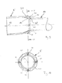
- einen stark vereinfachten Längsschnitt durch einen Schalldämpfer,
- Fig. 2 bis 8
- Längsschnitte des Schalldämpfers im Bereich eines seitlich ange-ordneten Rohres, bei verschiedenen Ausführungsformen,
- Fig. 9
- einen Längsschnitt des Schalldämpfers wie in den
Fig. 2 bis 8 , jedoch bei einer weiteren Ausführungsform, - Fig. 10
- einen Querschnitt entsprechend den Schnittlinien X in
Fig. 9 , - Fig. 11
- einen Längsschnitt wie in
Fig. 9 , jedoch bei einer anderen Ausführungsform, - Fig. 12
- einen Querschnitt entsprechend Schnittlinien XII in
Fig. 11 . - Entsprechend
Fig. 1 umfasst ein Schalldämpfer 1 zwei voneinander abgewandte stirnseitige Endböden 2, einen im Umfangsrichtung geschlossen umlaufenden Mantel 3, zumindest einen Schalldämpfereinsatz 4, zumindest ein Einlassrohr 5 und zumindest ein Auslassrohr 6. - Der Schalldämpfer 1 ist zum Einbau in eine nicht gezeigte Abgasanlage einer Brennkraftmaschine vorgesehen und kann insbesondere in einem Kraftfahrzeug verwendet werden. Vorzugsweise handelt es sich beim Schalldämpfer 1 um einen Nachschalldämpfer, also um den Schalldämpfer, der innerhalb der Abgasanlage bzgl. der Abgasströmungsrichtung der zuletzt durchströmte Schalldämpfer ist, bevor das Abgas zum jeweiligen Endrohr der Abgasanlage gelangt, das die Mündung der Abgasanlage zur Umgebung besitzt. Besonders vorteilhaft handelt es sich beim Schalldämpfer um einen im montierten Zustand quer liegend angeordneten Schalldämpfer. Beim quer liegenden Schalldämpfer 1 erstreckt sich eine Axialrichtung 7 des Schalldämpfers 1 im Wesentlichen parallel zu einer horizontalen Querrichtung des Fahrzeugs. Um den Schalldämpfer 1 einfacher quer im Fahrzeug einbauen zu können, erstreckt sich zumindest eines der Rohre, also zumindest ein Einlassrohr 5 und/oder ein Auslassrohr 6, durch den Mantel 3 in das Schalldämpferinnere 8 hinein. Im gezeigten Beispiel erstreckt sich genau ein Rohr, nämlich das Einlassrohr 5 durch den Mantel 3 hindurch. Bevorzugt ist auch nur ein einziges Einlassrohr 5 vorgesehen. Im Unterschied dazu können auch mehr als ein Auslassrohr 6 vorgesehen sein. Das Beispiel der
Fig. 1 zeigt zwei Auslassrohre 6. Obwohl in der nachfolgenden Beschreibung immer nur das Einlassrohr 5 das seitlich den Mantel 3 durchdringende Rohr 5, 6 ist, kann bei einer anderen Ausführungsform mit entgegengesetzter Strömungsrichtung auch das Auslassrohr 6 das seitlich den Mantel 3 durchdringende Rohr 5, 6 sein. Ebenso ist eine Ausführungsform möglich, bei der sowohl wenigstens ein Einlassrohr 5 als auch wenigstens ein Auslassrohr 6 seitlich angeordnet sind und den Mantel 3 durchdringen. Optional können auch alle zu- bzw. abführenden Rohre 5, 6 seitlich an den Mantel 3 angeschlossen sein. - Das Einlassrohr 5 ist am Mantel 3 befestigt. Im Beispiel ist zumindest eine Schweißverbindung 9 vorgesehen, mit der das Einlassrohr 5 am Mantel 3 befestigt ist. Hierbei kann es sich z.B. um eine ringförmig geschlossen umlaufende Schweißnaht handeln, wodurch gleichzeitig eine gasdichte Verbindung geschaffen wird. Alternativ ist es ebenso möglich z.B. bei der Herstellung des Schalldämpfers 1 das Einlassrohr 5 mittels wenigstens eines Schweißpunktes oder einer Verheftung am Mantel 3 zu befestigen. Beim Einbau des Schalldämpfers 1 in eine Abgasanlage kann dann ein entsprechendes Zuführrohr 29 an das Einlassrohr 5 angeschlossen werden. Beim Befestigen des Zuführrohrs 29 kann dann eine umlaufende Schweißnaht erzeugt werden. Bevorzugt wird dann die Anbringung einer Dreiblechnaht, die gleichzeitig drei Bleche, also hier das Einlassrohr 5, den Mantel 3 und das Zuführrohr 29 miteinander verbindet.
- Das Einlassrohr 5 durchsetzt hierzu eine seitlich in den Mantel 3 eingearbeitete Öffnung 17. Die jeweilige Schweißverbindung 9 kann dabei an einem stirnseitigen Ende eines nach außen ausgestellten Kragens 18 ausgebildet sein, der die Öffnung 17 umschließt.
- Im Inneren 8 weist das Einlassrohr 5 einen Konus 10 auf, der mit einem dazu passend bzw. komplementär geformten Gegenkonus 11 in Eingriff steht, der am Schalldämpfereinsatz 4 vorgesehen ist. Durch diesen formschlüssigen Eingriff zwischen dem Konus 10 und dem dazu geeignet geformten Gegenkonus 11 ergibt sich für das Einlassrohr 5 bzgl. seiner Rohrlängsachse 12 eine radiale und axiale Abstützung am Schalldämpfereinsatz 4. Somit ist das Einlassrohr 5 einerseits am Mantel 3 und andererseits beabstandet dazu über den in den Gegenkonus 11 eingreifenden Konus 10 am Schalldämpfereinsatz 4 abgestützt. Hierdurch kann das Einlassrohr 5 Momente aufnehmen und die im Betrieb auftretenden Kräfte ohne Weiteres abstützen.
- Bei allen gezeigten Beispielen der
Fig. 1 bis 12 ist jeweils der Konus 10 in den Gegenkonus 11 eingesteckt, so dass der Konus 10 in den Gegenkonus 11 eingreift. Diese Ausführungsform eignet sich in besonderer Weise für die Montage des Schalldämpfers 1. Grundsätzlich ist jedoch auch eine umgekehrte Bauform denkbar, bei welcher der Konus 10 auf den Gegenkonus 11 aufgesteckt ist bzw. bei welcher der Gegenkonus 11 in den Konus 10 eingesteckt ist bzw. darin eingreift. Diese umgekehrte Bauform ist - soweit sinnvoll - bei allen vorstehend und nachfolgend beschriebenen Ausführungsformen für die Ausgestaltungen von Konus 10 und Gegenkonus 11 realisierbar. - Besonders vorteilhaft ist es, wenn das Einlassrohr 5 so angebracht ist, dass es unter einer bzgl. der Rohrlängsachse 12 axialen Vorspannung am Schalldämpfereinsatz 4 abgestützt ist. Diese axiale Vorspannung ist in
Fig. 1 durch einen Doppelpfeil angedeutet und mit 13 bezeichnet. Die axiale Vorspannung 13 wirkt zwischen dem Schalldämpfereinsatz 4 und dem Mantel 3 und wird über das Einlassrohr 5 zwischen dem Mantel 3 und dem Schalldämpfereinsatz 4 übertragen. Mit anderen Worten, das Einlassrohr 5 greift mit seinem Konus 10 unter der axialen Vorspannung 13 in den Gegenkonus 11 ein. - Bevorzugt ist dabei eine Ausführungsform, bei welcher die axiale Vorspannung 13 nicht beliebig gewählt ist, sondern einen vorbestimmten Wert besitzt. Insbesondere kann die axiale Vorspannung 13 gezielt so groß eingestellt sein, dass eine axiale Mindestvorspannung für den gesamten im Betrieb des Schalldämpfers zu erwartenden Temperaturbereich gewährleistet ist. Der thermische Betriebsbereich kann bei einer Fahrzeuganwendung bspw. von -40°C bis +500°C reichen, sofern es sich um einen Nachschalldämpfer handelt.
- Der Konus 10 ist am Einlassrohr 5 zweckmäßig integral ausgeformt. Bspw. ist das innenliegende Ende des Einlassrohrs 5 zum Herstellen des Konus 10 umgeformt. Grundsätzlich ist jedoch auch eine gebaute Variante möglich.
- Der Gegenkonus 11 ist an einem Zwischenrohr 14 des Schalldämpfereinsatzes 4 ausgebildet. Dieses Zwischenrohr 14 ist hier an einem Zwischenboden 15 des Schalldämpfereinsatzes 4 befestigt, der zwischen den beiden Endböden 2 angeordnet ist.
- Zweckmäßig ist der Gegenkonus 11 am Zwischenrohr 14 integral ausgeformt. Ebenso ist eine gebaute Ausführung möglich. Zweckmäßig ist das Zwischenrohr 14 so konfiguriert, dass es im Bereich des Gegenkonus 11 in der Rohrlängsachse 12 federelastisch nachgiebig ist. Diese federelastische Nachgiebigkeit vereinfacht die Erzeugung der axialen Vorspannung 13. Beim Montieren wird das Zwischenrohr 14 quasi wie eine Feder gespannt, um die Vorspannung 13 zu erzeugen. Um eine vergleichsweise hohe Vorspannung 13 erzeugen zu können, ist das Zwischenrohr 14 mit einer vergleichsweise hohen Federsteifigkeit bzw. Stabilität ausgestaltet. Dies kann bspw. dadurch realisiert werden, dass das Zwischenrohr 14 wie im gezeigten Beispiel gekrümmt ist und an zwei Zwischenböden 15 und 30 abgestützt ist.
- Der Mantel 3 ist durch Wickeln eines Blechteils gebildet. Dementsprechend handelt es sich hier um einen in der Wickelbauweise hergestellten Schalldämpfer 1. Bspw. kann der Mantel 3 einen Längsfalz 16 aufweisen, der sich parallel zur Schalldämpferlängsachse 7 erstreckt. Zweckmäßig ist der Längsfalz 16 an einer vom Einlassrohr 5 abgewandten Seite positioniert.
- Zumindest einer der Endböden 2, hier der in
Fig. 1 rechts dargestellte Endboden 2, kann ein Bestandteil des Schalldämpfereinsatzes 4 sein. Entsprechend der Wickelbauweise des Schalldämpfers 1 ist der Schalldämpfereinsatz 4 axial, also parallel zur Schalldämpferlängsachse 7 und somit stirnseitig in den Mantel 3 eingesetzt. Dabei kann zweckmäßig vorgesehen sein, die Außenabmessung des Einsatzes 4 und die Innenabmessung des Mantels 3 so aufeinander abzustimmen, dass der Schalldämpfereinsatz 4 bezogen auf die Schalldämpferlängsachse 7 unter radialer Vorspannung am Mantel 3 anliegt bzw. gehalten ist. - Das jeweilige Auslassrohr 6 erstreckt sich durch einen der Endböden 2, hier durch den in
Fig. 1 rechts dargestellten Endboden 2, der im Beispiel zum Schalldämpfereinsatz 4 gehört. Außerdem erstreckt sich das jeweilige Auslassrohr 6 im Beispiel durch einen weiteren Zwischenboden 31, der hier ebenfalls zur Positionierung und Stabilisierung des Zwischenrohrs 14 vorgesehen ist. Das jeweilige Auslassrohr 6 ist zumindest am Endboden 2 befestigt, bspw. mittels einer Schweißverbindung 20, um auch hier eine gasdichte Anbindung zu realisieren. Die Endböden 2 sind axial an den Mantel 3 angesetzt bzw. darin eingesetzt und mit dem Mantel 2 fest verbunden, z. B. mit einer umlaufenden Falzverbindung 21. - Entsprechend
Fig. 1 kann sich der Konus 10 in der Umfangsrichtung des Einlassrohrs 5 ringförmig geschlossen am Gegenkonus 11 abstützen. Hierdurch ist in jeder Richtung eine radiale Abstützung des Einlassrohrs 5 am Schalldämpfereinsatz 4 möglich. - Wie
Fig. 1 zu entnehmen ist, sind Konus 10 und Gegenkonus 11 vom Mantel 3 beabstandet angeordnet. Erreicht wird dies durch eine vom Mantel 3 in der Rohrlängsachse 12 beabstandete Positionierung des freien dem jeweiligen Rohr 5 zugewandten Endes 19 des Zwischenrohrs 14 gegenüber dem Mantel 3. Quer zur Rohrlängsachse 12 ist das Zwischenrohr 14 an den Zwischenböden 15, 30 abgestützt. Insbesondere ist das Zwischenrohr 14 etwa mittig im Schalldämpferinneren 8 angeordnet, und zwar bezogen auf die Rohrlängsachse 12. - Das Einlassrohr 5 ist axial offen, so dass das Abgas durch den Konus 10 und durch den Gegenkonus 11 in das Zwischenrohr 14 einströmen kann. Im Beispiel ragt das Einlassrohr 5 durch den Mantel 3 hindurch in einen Raum 22 ein, der im Schalldämpferinneren 8 mit Hilfe des Schalldämpfereinsatzes 4 ausgebildet ist. Besagter Raum 22 ist durch die Zwischenwände 15, 30 und durch einen Abschnitt des Mantels 3 seitlich begrenzt. Die Zwischenwände 15, 30, 31 können gasdurchlässig bzw. schalldurchlässig ausgestaltet sein, bspw. mittels Öffnungen bzw. mittels einer Perforation. Das eine Auslassrohr 6 ist im gezeigten Beispiel über das Zwischenrohr 14 mit dem Einlassrohr 5 fluidisch verbunden und führt aus dem Schalldämpfer 1 heraus. Zumindest eines der Austrittsrohre 6 kann eine Perforation 23 aufweisen, um mit einem Raum 24 zu kommunizieren, der zwischen der Zwischenwand 31 und dem benachbarten Endboden 2 ausgebildet ist. Auch die Zwischenwand 31 kann, beispielsweise mittels einer Perforation, gasdurchlässig bzw. schalldurchlässig ausgestaltet sein, um das Volumen des Raums 24 bis zum Zwischenboden 15 zu vergrößern, so dass bspw. auch ein Raum 25, der zwischen den Zwischenböden 15 und 31 ausgebildet ist, z.B. als Adsorptionskammer genutzt werden kann.
- Gemäß
Fig. 1 verbindet das Zwischenrohr 14 das Einlassrohr 5 mit dem einen Auslassrohr 6. Somit kann das Abgas direkt und somit ohne großen Druckverlust, den Schalldämpfer 1 durchströmen. Sofern - wie hier - das Einlassrohr 5 den Mantel 3 durchsetzt und das jeweilige Auslassrohr 6 einen der Endböden 2 durchsetzt, ist das Zwischenrohr 14 zweckmäßig gebogen. Im Beispiel derFig. 1 besitzt das Zwischenrohr 14 eine Biegung von etwa 90°. Dementsprechend erzeugt es eine Strömungsumlenkung von etwa 90°. - Das Zwischenrohr 14 kann gemäß
Fig. 1 mit einem Abzweigrohr 26 fluidisch verbunden sein. Das Abzweigrohr 26 mündet in einen Resonanzraum 32 ein. Der Resonanzraum 32 ist im Beispiel durch den einen Zwischenboden 30 und durch den dazu benachbarten Endboden 2 axial und in Umfangsrichtung durch den Mantel 3 begrenzt. Hierdurch wird ein Helmholtz-Resonator erzeugt. Der Resonanzraum 32 kann nun über zumindest ein Verbindungsrohr 33 mit dem Raum 25 fluidisch verbunden sein, der im folgenden auch als Zusatzraum 25 bezeichnet wird. An diesen Zusatzraum 25 ist ein weiteres Rohr 34 angeschlossen, bei dem es sich im Beispiel um ein weiteres Auslassrohr 6 handelt. Somit ist es möglich, dass Abgas vom Zwischenrohr 14 über das Abzweigrohr 26, durch den Resonanzraum 32, über das Verbindungsrohr 33 in den Zusatzraum 25 gelangt und über das weitere Auslassrohr 6 bzw. 34 aus dem Schalldämpfer 1 austritt. - Der Raum 22, der im folgenden auch als Zwischenraum 22 bezeichnet werden kann, kann optional schallübertragend gekoppelt sein mit dem Resonanzraum 32 und/oder mit dem Zusatzraum 25 und/oder mit dem Inneren des Verbindungsrohrs 33 und/oder mit dem Inneren des Zwischenrohrs 14. Die jeweilige schall-übertragende Verbindung kann beispielsweise mittels einer Perforation 35 realisiert werden, die in dem den Zwischenraum 22 vom Resonanzraum 32 trennenden Zwischenboden 30 ausgebildet ist. Ebenso kann eine derartige Perforation 35 in dem den Zwischenraum 22 vom Zusatzraum 25 trennenden Zwischenboden 15 ausgebildet sein. Ebenso kann das Verbindungsrohr 33 eine derartige Perforation aufweisen. Schließlich kann grundsätzlich auch das Zwischenrohr 14 eine derartige Perforation 35 besitzen.
- Bei geringen Abgasvolumenströmen strömt das Abgas weitgehend direkt vom Einlassrohr 5 über das Zwischenrohr 14 zum Auslassrohr 6 durch den Schalldämpfer 1. Bei größeren Volumenströmen kann sich ein zunehmender zusätzlicher Abgasstrom über das Abzweigrohr 26, das Verbindungsrohr 33 und das weitere Auslassrohr 6 ausbilden.
- Entsprechend den
Figuren 2 bis 12 sind für den Konus 10 und den Gegenkonus 11 unterschiedliche Konfigurationen bzw. Ausführungsformen realisierbar. Bspw. kann der Konus 10 gemäß denFiguren 2 und 6 bis 8 eine kegelsegmentförmige Außenkontur 27 aufweisen. Gemäß denFiguren 3 bis 5 kann die Außenkontur 27 des Konus 10 auch kugelsegmentförmig gestaltet sein. Ebenso sind andere Formen für die Außenkontur 27 denkbar. - Gemäß den
Figuren 2 und 6 bis 8 kann der Gegenkonus 11 eine kegelsegmentförmige Innenkontur 28 aufweisen. Bei aufeinander abgestimmten Winkeln und koaxialer Ausrichtung von Konus 10 und Gegenkonus 11 ergibt sich hierbei eine besonders intensive flächige und ringförmig geschlossene Abstützung des Einlassrohrs 5 am Zwischenrohr 14. - Der Gegenkonus 11 kann jedoch auch eine kugelsegmentförmige Innenkontur 28 gemäß
Fig. 4 oder eine trichterförmige Innenkontur 28 gemäßFig. 5 aufweisen. Die trichterförmige Innenkontur 28 gemäßFig. 5 charakterisiert sich gegenüber der kugelsegmentförmigen Innenkontur 28 ausFig. 4 und gegenüber der kegelsegmentförmigen Innenkontur 28 derFiguren 2 und 6 bis 8 dadurch, dass die Innenkontur 28 ein gekrümmtes Profil aufweist, das zum Konus 10 hin konvex ist. - Bei den Ausführungsformen der
Figuren 3 bis 5 trifft ein Konus 10 mit kugelsegmentförmiger Außenkontur 27 auf eine kegelsegmentförmige Innenkontur 28 (Fig. 3 ) bzw. auf eine kugelsegmentförmige Innenkontur 28 (Fig. 4 ) bzw. auf eine trichterförmige Innenkontur 28 (Fig. 5 ) des Gegenkonus 11. Bei diesen Ausführungsformen kommt es auch dann zu einer in Umfangsrichtung geschlossenen linienförmigen Kontaktierung zwischen Konus 10 und Gegenkonus 11, wenn keine exakte koaxiale Ausrichtung zwischen Konus 10 und Gegenkonus 11 vorliegt. Diese Ausführungsformen ermöglichen damit einen Ausgleich von Herstellungstoleranzen. Bevorzugt ist dabei die Ausführungsform gemäßFig. 3 , bei der eine kugelsegmentförmige Außenkontur 27 des Konus 10 mit einer kegelsegmentförmigen Innenkontur 28 des Gegenkonus 11 zusammenwirkt. Diese Ausführungsform ist vergleichsweise preiswert realisierbar. - Bei den Ausführungsformen der
Fig. 1 bis 5 und 7 ist der Konus 10 jeweils an einem innenliegenden Ende des Einlassrohrs 5 ausgebildet. Ferner ist bei den Ausführungsformen derFig. 1 bis 6 der Gegenkonus 11 jeweils an einem dem Einlassrohr 5 zugewandten Ende 19 des Zwischenrohrs 14 ausgebildet. - Bei den Ausführungsformen der
Fig. 6 und 8 ist der Konus 10 zwischen einem innenliegenden Endabschnitt 36 des Einlassrohrs 5 und einem Abschnitt 37 des Einlassrohrs 5 ausgebildet, der am Mantel 3 befestigt ist. Dementsprechend ist der Konus 10 bei diesen Ausführungsformen vom innenliegenden axialen Ende des Einlassrohrs 5 beabstandet positioniert. Der Endabschnitt 36, der axial über den Konus 10 vorsteht, bildet einen Steckabschnitt, der in das Zwischenrohr 14, durch den Gegenkonus 11 hindurch, eingesteckt werden kann. Dabei können die Außenabmessung des Endabschnitts 36 und die Innenabmessung des Zwischenrohrs 14 so aufeinander abgestimmt sein, dass sich nur ein geringes Spiel oder kein Spiel oder sogar ein Presssitz einstellt. Mit Hilfe eines derartigen in das Zwischenrohr 14 eintauchenden Endabschnitts 36 kann die radiale Abstützung des Einlassrohrs 5 über das Zwischenrohr 14 am übrigen Schalldämpfereinsatz 4 signifikant verbessert werden. - Zusätzlich oder alternativ ist es gemäß den
Fig. 7 und 8 möglich, den Gegenkonus 11 zwischen einem dem Einlassrohr 5 zugewandten Endabschnitt 38 des Zwischenrohrs 14 und einem Abschnitt 39 des Zwischenrohrs 14 auszubilden, über den das Zwischenrohr 14 am Schalldämpfereinsatz 4 befestigt ist. Mit anderen Worten, der Gegenkonus11 ist bei diesen Ausführungsformen von dem dem Einlassrohr 5 zugewandten Ende 19 des Zwischenrohrs 14 beabstandet angeordnet. Der über den Gegenkonus 11 axial vorstehende Endabschnitt 38 des Zwischenrohrs 14 ist so abgemessen, dass er von außen auf das Einlassrohr 5 aufgesteckt werden kann. Mit anderen Worten, das Einlassrohr 5 wird mit seinem Konus 10 in den Endabschnitt 38 des Zwischenrohrs 14 eingesteckt, um mit dem Gegenkonus 11 in Eingriff zu kommen. Zweckmäßig können auch hier die Außenabmessung des Einlassrohrs 5 und die Innenabmessung des Endabschnitts 38 so aufeinander abgestimmt sein, dass sich ein geringfügiges Radialspiel oder kein Radialspiel oder sogar ein Presssitz ausbildet. Auch diese Maßnahme führt zu einer Aussteifung der Kopplung zwischen Einlassrohr 5 und Zwischenrohr 14, welche die radiale Abstützung des Einlassrohrs 5 über das Zwischenrohr 14 am Schalldämpfereinsatz 14 verbessert. - Bei der in
Fig. 6 gezeigten Ausführungsform besitzt nur das Einlassrohr 5 einen über den Konus 10 vorstehenden Endabschnitt 36. Bei der inFig. 7 gezeigten Ausführungsform besitzt nur das Zwischenrohr 14 einen über den Gegenkonus 11 vorstehenden Endabschnitt 38. Bei der inFig. 8 gezeigten Ausführungsform besitzt sowohl das Einlassrohr 5 einen über den Konus 10 vorstehenden Endabschnitt 36 als auch das Zwischenrohr 14 einen über den Gegenkonus 11 vorstehenden Endabschnitt 38. - Entsprechend den
Fig. 9 und 10 kann der Konus 10 in der Umfangsrichtung verteilt mehrere Vorsprünge 40 aufweisen, die gegenüber der übrigen Außenkontur 27 nach außen vorstehen. Über diese Vorsprünge 40 stützt sich der Konus 10 am Gegenkonus 11 ab. Insbesondere können sich dadurch in der Umfangsrichtung zwischen den Vorsprüngen 40 Durchgangsöffnungen 41 ausbilden. Im Beispiel sind rein exemplarisch genau vier derartige Vorsprünge 40 vorgesehen, die in der Umfangsrichtung außerdem symmetrisch verteilt angeordnet sind. Es ist klar, dass wenigstens drei derartige Vorsprünge 40 vorhanden sind wobei die Anzahl der Vorsprünge 40 zweckmäßig auf fünfzehn oder zehn beschränkt ist. Alternativ ist es ebenso möglich, den Gegenkonus 11 mit derartigen Vorsprüngen auszustatten, die dann an der Innenkontur 28 nach innen vorstehen. - Gemäß den
Fig. 11 und 12 können gemäß einer anderen Option am Konus 10 mehrere in Umfangsrichtung verteilt angeordnete Schlitze 42 ausgebildet sein, die sich jeweils axial erstrecken und die jeweils einseitig offen sind und die den Konus 10 in der Umfangsrichtung in mehrere Konussegmente 43 unterteilen. Mit anderen Worten, die Schlitze 42 trennen in der Umfangsrichtung die Konussegmente 43 voneinander. Hierdurch erhält der Konus 10 innerhalb der Konussegmente 43 eine erhöhte radiale Federelastizität. Hierdurch lässt sich eine verbesserte Abstützung realisieren. Zusätzlich oder alternativ kann der Gegenkonus 11 ebenfalls mit derartigen Schlitzen ausgestattet sein, die in der Umfangsrichtung verteilt angeordnet sind, sich axial erstrecken, axial einseitig offen sind und die den Gegenkonus 11 in der Umfangsrichtung in mehrere Gegenkonussegmente unterteilen. Im Beispiel derFig. 11 und 12 sind ohne Beschränkung der Allgemeinheit genau vier derartige Schlitze 42 ausgebildet, die außerdem symmetrisch verteilt angeordnet sind. Es ist klar, dass auch mehr oder weniger als vier derartige Schlitze 42 realisiert werden können. - Die vorstehend mit Bezug auf die
Fig. 9 bis 12 vorgestellten Maßnahmen lassen sich miteinander kombinieren, so dass beispielsweise ein Vorsprung 40 in der Umfangsrichtung zwischen zwei benachbarten Schlitzen 42 am jeweiligen Konussegment 43 angeordnet sein kann. Desweiteren lassen sich die in denFig. 9 bis 12 vorgestellten Maßnahmen mit dem in denFig. 2 bis 8 vorgestellten Konfigurationen kombinieren. - Die Vorsprünge 40 bzw. die Schlitze 42 vereinfachen einen Toleranzausgleich und verbessern die Abstützungswirkung zwischen Konus 10 und Gegenkonus 11.
- Der hier vorgestellte Schalldämpfer 1 lässt sich vorzugsweise wie folgt herstellen:
- Zunächst wird der jeweilige Schalldämpfereinsatz 4 stirnseitig, also parallel zur Schalldämpferlängsachse 7 in den Mantel 3 eingeschoben. Anschließend wird das Einlassrohr 5 seitlich in die Öffnung 17 des Mantels 3 eingesteckt, und zwar soweit, bis der Konus 10 und der Gegenkonus 11 miteinander in Eingriff stehen. Anschließend wird das Einlassrohr 5 am Mantel 3 befestigt.
- Bevorzugt wird vor dem Befestigen des Einlassrohrs 5 am Mantel 3 dabei das Einlassrohr 5 soweit durch die Öffnung 17 in das Schalldämpferinnere 8 eingesteckt, bis das Einlassrohr 5 über den mit dem Gegenkonus 11 in Eingriff stehenden Konus 10 mit der axialen Vorspannung 13, insbesondere mit der vorbestimmten axialen Vorspannung 13, am Schalldämpfereinsatz 4 abgestützt ist. Die Befestigung des Einlassrohrs 5 am Mantel 3, also insbesondere das Anbringen der Schweißverbindung 9, erfolgt dann bei aufrechterhaltener axialer Vorspannung 13, also während das Einlassrohr 5 axial vorgespannt am Schalldämpfereinsatz 4 abgestützt ist. Hierdurch kann die zuvor, insbesondere gezielt, aufgebrachte Vorspannung 13 konserviert werden.
Claims (13)
- Schalldämpfer für eine Abgasanlage einer Brennkraftmaschine, insbesondere eines Kraftfahrzeugs,- mit zwei voneinander abgewandten stirnseitigen Endböden (2),- mit einem in Umfangsrichtung geschlossen umlaufenden Mantel (3),- mit wenigstens einem Schalldämpfereinsatz (4),- mit wenigstens einem Einlassrohr (5),- mit wenigstens einem Auslassrohr (6),- wobei zumindest eines der Rohre (5,6) sich durch den Mantel (3) in das Schalldämpferinnere (8) erstreckt und am Mantel (3) befestigt ist,
dadurch gekennzeichnet,- dass das sich durch den Mantel (3) erstreckende Rohr (5,6) einen Konus (10) aufweist,- dass der Schalldämpfereinsatz (4) ein Zwischenrohr (14) aufweist, das einen Gegenkonus (11) aufweist,- dass Konus (10) und Gegenkonus (11) ineinander eingreifen. - Schalldämpfer nach Anspruch 1,
dadurch gekennzeichnet,
dass das sich durch den Mantel (3) erstreckende Rohr (5,6) so angebracht ist, dass es unter axialer Vorspannung (13) über den mit dem Gegenkonus (11) zusammenwirkenden Konus (10) am Schalldämpfereinsatz (4) abgestützt ist. - Schalldämpfer nach Anspruch 2,
dadurch gekennzeichnet,
dass sich das jeweilige Rohr (5,6) unter einer vorbestimmten axialen Vorspannung (13) am Schalldämpfereinsatz (4) abstützt, die insbesondere so gewählt sein kann, dass über dem gesamten zu erwartenden thermischen Betriebsbereich des Schalldämpfers (1) eine axiale Mindestvorspannung erhalten bleibt. - Schalldämpfer nach einem der Ansprüche 1 bis 3,
dadurch gekennzeichnet,- dass der Konus (10) in den Gegenkonus (11) eingreift oder umgekehrt, und/oder- dass der Konus (10) eine kegelsegmentförmige oder kugelsegmentförmige Außenkontur (27) oder Innenkontur aufweist, und/oder- dass der Gegenkonus (11) eine kegelsegmentförmige oder kugelsegmentförmige oder trichterförmige Innenkontur (28) oder Außenkontur aufweist, und/oder- dass der Gegenkonus (11) komplementär zum Konus (10) geformt ist. - Schalldämpfer nach einem der Ansprüche 1 bis 4,
dadurch gekennzeichnet,- dass der Konus (10) integral am jeweiligen Rohr (5,6) ausgeformt ist, und/oder- dass der Gegenkonus (11) integral am Zwischenrohr (14) ausgeformt ist. - Schalldämpfer nach einem der Ansprüche 1 bis 5,
dadurch gekennzeichnet,- dass das Zwischenrohr (14) so ausgestaltet und/oder angebracht ist, dass es im Bereich des Gegenkonus (11) parallel zur Längsachse (12) des den Konus (10) aufweisenden Rohrs (5,6) federelastisch nachgiebig ist, und/oder- dass das Zwischenrohr (14) gebogen ist und eine Strömungsumlenkung von 90° erzeugt. - Schalldämpfer nach einem der Ansprüche 1 bis 6,
dadurch gekennzeichnet,- dass das Zwischenrohr (14) das Einlassrohr (5) mit dem Auslassrohr (6) fluidisch verbindet, und/oder- dass das Zwischenrohr (14) mit einem Abzweigrohr (26) fluidisch verbunden ist, das in einen Resonanzraum (32) einmündet, und/oder- dass der Resonanzraum (32) über wenigstens ein Verbindungsrohr (33) mit einem Zusatzraum (25) fluidisch verbunden ist, und/oder- dass der Zusatzraum (25) mit einem weiteren Rohr (34) fluidisch verbunden ist, das ebenfalls ein Auslassrohr (6) sein kann, und/oder- dass das Zwischenrohr (14) und/oder der Zusatzraum (25) und/oder der Resonanzraum (32) und/oder das Verbindungsrohr (33) mit einem Zwischenraum (22) schallübertragend verbunden ist/sind, in den das den Mantel (3) durchsetzende Rohr (5,6) hineinragt. - Schalldämpfer nach einem der Ansprüche 1 bis 7,
dadurch gekennzeichnet,- dass der Konus (10) an einem innenliegenden Ende des den Mantel (3) durchdringenden Rohrs (5,6) ausgebildet ist oder zwischen einem innenliegenden Endabschnitt (36) des den Mantel (3) durchdringenden Rohrs (5,6) und einem am Mantel (3) befestigten Abschnitt (37) dieses Rohrs (5,6) ausgebildet ist, wobei insbesondere vorgesehen sein kann, dass der Endabschnitt (36) durch den Gegenkonus (11) in das Zwischenrohr (14) eintaucht oder dass der Gegenkonus (11) in diesen Endabschnitt (36) eingesteckt ist, und/oder- dass der Gegenkonus (11) an einem dem jeweiligen Rohr (5,6) zugewandten Ende (19) des Zwischenrohrs (14) ausgebildet ist oder zwischen einem dem jeweiligen Rohr (5,6) zugewandten Endabschnitt (38) des Zwischenrohrs (14) und einem am Schalldämpfereinsatz (4) befestigten Abschnitt (39) des Zwischenrohrs (14) ausgebildet ist, wobei insbesondere vorgesehen sein kann, dass der Konus (10) in diesen Endabschnitt (38) eingesteckt ist oder dass dieser Endabschnitt (38) durch den Konus (10) in das jeweilige Rohr (5,6) eintaucht. - Schalldämpfer nach einem der Ansprüche 1 bis 8,
dadurch gekennzeichnet,- dass der Mantel (3) durch Wickeln eines Blechteils gebildet ist, und/oder- dass der Mantel (3) einen Längsfalz (16) aufweist, der sich insbesondere an einer von dem den Mantel (3) durchsetzenden Rohr (5,6) abgewandten Seite befindet, und/oder- dass zumindest einer der Endböden (2) einen Bestandteil des Schalldämpfereinsatzes (4) bildet, und/oder- dass der Schalldämpfereinsatz (4) stirnseitig in den Mantel (3) eingesetzt ist, und/oder- dass der Mantel (3) vorgespannt am Schalldämpfereinsatz (4) anliegt, und/oder- dass zumindest ein anderes der Rohre (5,6) sich durch einen der Endböden (2) erstreckt und am Endboden (2) befestigt ist. - Schalldämpfer nach einem der Ansprüche 1 bis 9,
dadurch gekennzeichnet,- dass sich der Konus (10) in Umfangsrichtung des jeweiligen Rohrs (5,6) ringförmig geschlossen am Gegenkonus (11) abstützt, und/oder- dass Konus (10) und Gegenkonus (11) vom Mantel (3) beabstandet sind, und/oder- dass das jeweilige Rohr (5,6) durch den Konus (10) und durch den Gegenkonus (11) hindurch mit dem Schalldämpferinneren (8), insbesondere mit einem durch den Schalldämpfereinsatz (4) im Schalldämpferinneren (8) ausgebildeten Raum (22), fluidisch verbunden ist. - Schalldämpfer nach einem der Ansprüche 1 bis 10,
dadurch gekennzeichnet,- dass der Konus (10) mehrere in Umfangsrichtung verteilt angeordnete Vorsprünge (40) aufweist, über die der Konus (10) am Gegenkonus (11) abgestützt ist, so dass insbesondere in Umfangsrichtung zwischen den Vorsprüngen (40) Durchtrittsöffnungen (41) zwischen Konus (10) und Gegenkonus (11) frei bleiben, und/oder- dass der Gegenkonus (11) mehrere in Umfangsrichtung verteilt angeordnete Vorsprünge aufweist, über die der Gegenkonus (11) am Konus (10) abgestützt ist, so dass insbesondere in Umfangsrichtung zwischen den Vorsprüngen Durchtrittsöffnungen zwischen Konus (10) und Gegenkonus (11) frei bleiben, und/oder- dass der Konus (10) mehrere in Umfangsrichtung verteilt angeordnete Schlitze (42) aufweist, die sich axial erstrecken, die axial einseitig offen sind und die in Umfangsrichtung mehrere Konussegmente (43) voneinander trennen, und/oder- dass der Gegenkonus (11) mehrere in Umfangsrichtung verteilt angeordnete Schlitze aufweist, die sich axial erstrecken, die axial einseitig offen sind und die in Umfangsrichtung mehrere Gegenkonussegmente voneinander trennen. - Verfahren zum Herstellen eines Schalldämpfers (1) für eine Abgasanlage einer Brennkraftmaschine, insbesondere eines Kraftfahrzeugs,- bei dem zumindest ein Schalldämpfereinsatz (4) stirnseitig in einen in Umfangsrichtung geschlossen umlaufenden Mantel (3) eingeschoben wird,- bei dem zumindest ein Rohr (5,6) seitlich in eine Öffnung (17) des Mantels (3) soweit eingesteckt wird, bis ein Konus (10) am vorausgehenden Ende des Rohrs (5,6) und ein an einem Zwischenrohr (14) des Schalldämpfereinsatzes (4) ausgebildeter Gegenkonus (11) ineinander eingreifen,- bei dem das jeweilige Rohr (5,6) am Mantel (3) befestigt wird.
- Verfahren nach Anspruch 12,
dadurch gekennzeichnet,- dass das jeweilige Rohr (5,6) soweit eingesteckt wird, dass das Rohr (5,6) über den mit dem Gegenkonus (11) zusammenwirkenden Konus (10) mit axialer Vorspannung (13) am Schalldämpfereinsatz (4) abgestützt ist,- dass das jeweilige Rohr (5,6) am Mantel (3) befestigt wird, während es axial vorgespannt am Schalldämpfereinsatz (4) abgestützt ist.
Applications Claiming Priority (1)
| Application Number | Priority Date | Filing Date | Title |
|---|---|---|---|
| DE102010019959A DE102010019959A1 (de) | 2010-05-08 | 2010-05-08 | Schalldämpfer |
Publications (2)
| Publication Number | Publication Date |
|---|---|
| EP2385225A1 true EP2385225A1 (de) | 2011-11-09 |
| EP2385225B1 EP2385225B1 (de) | 2014-10-29 |
Family
ID=44189197
Family Applications (1)
| Application Number | Title | Priority Date | Filing Date |
|---|---|---|---|
| EP11157294.7A Not-in-force EP2385225B1 (de) | 2010-05-08 | 2011-03-08 | Schalldämpfer |
Country Status (4)
| Country | Link |
|---|---|
| US (1) | US8292026B2 (de) |
| EP (1) | EP2385225B1 (de) |
| CN (1) | CN102235222B (de) |
| DE (1) | DE102010019959A1 (de) |
Cited By (1)
| Publication number | Priority date | Publication date | Assignee | Title |
|---|---|---|---|---|
| CN107687362A (zh) * | 2016-08-03 | 2018-02-13 | 波森公司 | 用于排气系统的组件及其制造方法 |
Families Citing this family (30)
| Publication number | Priority date | Publication date | Assignee | Title |
|---|---|---|---|---|
| DE102010062569A1 (de) * | 2010-12-07 | 2012-06-14 | J. Eberspächer GmbH & Co. KG | Gehäuse |
| DE102011077183B4 (de) * | 2011-06-08 | 2015-05-21 | Eberspächer Exhaust Technology GmbH & Co. KG | Schalldämpfer und Herstellungsverfahren |
| US8602157B2 (en) * | 2011-11-03 | 2013-12-10 | Don Emler | Q4 muffler assembly |
| KR20130073710A (ko) * | 2011-12-23 | 2013-07-03 | 삼성전자주식회사 | 연료 전지 시스템의 소음을 저감하기 위한 소음기 |
| US9188048B2 (en) * | 2012-12-20 | 2015-11-17 | Bombardier Recreational Products Inc. | Vehicle having an auxiliary exhaust pipe |
| CA2897293C (en) * | 2013-01-11 | 2017-05-02 | Futaba Industrial Co., Ltd. | Method for installing inlet pipe and method for supporting inlet pipe |
| US8985272B1 (en) * | 2013-10-24 | 2015-03-24 | Kawasaki Jukogyo Kabushiki Kaisha | Exhaust muffler for vehicle |
| US8985271B1 (en) * | 2013-10-24 | 2015-03-24 | Kawasaki Jukogyo Kabushiki Kaisha | Exhaust muffler for vehicle |
| DE102014110098A1 (de) | 2014-07-18 | 2016-01-21 | Friedrich Boysen Gmbh & Co. Kg | Schalldämpfer |
| DE102014217058A1 (de) * | 2014-08-27 | 2016-03-03 | Eberspächer Exhaust Technology GmbH & Co. KG | Schalldämpfer |
| DE102014221151B4 (de) * | 2014-10-17 | 2022-12-08 | Purem GmbH | Komponente einer Abgasanlage |
| DE102015113159A1 (de) * | 2015-08-10 | 2017-02-16 | Faurecia Emissions Control Technologies, Germany Gmbh | Bauteil einer Abgasanlage |
| US10196947B2 (en) | 2016-02-02 | 2019-02-05 | Kohler Co. | Muffler |
| CN106351712B (zh) * | 2016-10-14 | 2018-08-28 | 上海天纳克排气系统有限公司 | 消声器 |
| EP3431732B1 (de) | 2017-07-21 | 2020-04-22 | Bosal Emission Control Systems NV | Verfahren zur formung eines kragens in einem schalldämpfergehäuse |
| DE102018124198A1 (de) | 2017-10-05 | 2019-04-11 | Tenneco Automotive Operating Company Inc. | Akustisch abgestimmter Schalldämpfer |
| US11365658B2 (en) | 2017-10-05 | 2022-06-21 | Tenneco Automotive Operating Company Inc. | Acoustically tuned muffler |
| US11199116B2 (en) * | 2017-12-13 | 2021-12-14 | Tenneco Automotive Operating Company Inc. | Acoustically tuned muffler |
| JP6822985B2 (ja) * | 2018-01-05 | 2021-01-27 | フタバ産業株式会社 | 消音装置 |
| US10900396B2 (en) * | 2018-01-15 | 2021-01-26 | Ford Global Technologies, Llc | Exhaust orifice tube for vehicle mufflers |
| US10882578B2 (en) * | 2018-06-13 | 2021-01-05 | Magnum Shielding Corporation | Increasing the internal pivot radii for angle-joined motorcycle handle bars |
| CN109057917A (zh) * | 2018-09-27 | 2018-12-21 | 上海天纳克排气系统有限公司 | 消音器 |
| US11268429B2 (en) | 2019-01-17 | 2022-03-08 | Tenneco Automotive Operating Company Inc. | Diffusion surface alloyed metal exhaust component with inwardly turned edges |
| US11268430B2 (en) | 2019-01-17 | 2022-03-08 | Tenneco Automotive Operating Company Inc. | Diffusion surface alloyed metal exhaust component with welded edges |
| US10975743B1 (en) | 2020-03-13 | 2021-04-13 | Tenneco Automotive Operating Company Inc. | Vehicle exhaust component |
| CN213747266U (zh) * | 2020-09-27 | 2021-07-20 | 珠海华宇金属有限公司 | 空调消音器 |
| DE102021106764A1 (de) * | 2021-03-19 | 2022-09-22 | Friedrich Boysen GmbH & Co KG. | Schalldämpfer |
| DE102021113611A1 (de) * | 2021-05-26 | 2022-12-01 | Umfotec Gmbh | Schallminderer, Verfahren zu dessen Herstellung und Fluidleitungssystem mit einem solchen Schallminderer |
| DE102021114254A1 (de) | 2021-06-02 | 2022-12-08 | Purem GmbH | Schalldämpfer und Verfahren zur Herstellung eines Schalldämpfers |
| DE102021115962A1 (de) * | 2021-06-21 | 2022-12-22 | Purem GmbH | Schalldämpfer und Verfahren zur Herstellung eines Schalldämpfers |
Citations (3)
| Publication number | Priority date | Publication date | Assignee | Title |
|---|---|---|---|---|
| GB2303315A (en) * | 1993-01-11 | 1997-02-19 | Fuji Heavy Ind Ltd | Engine exhaust apparatus |
| DE102005026376A1 (de) * | 2005-06-08 | 2006-12-14 | Arvinmeritor Emissions Technologies Gmbh | Fahrzeugschalldämpfer |
| EP2149687A1 (de) * | 2007-05-30 | 2010-02-03 | Yamaha Hatsudoki Kabushiki Kaisha | Abgasvorrichtung und sattelfahrzeug |
Family Cites Families (13)
| Publication number | Priority date | Publication date | Assignee | Title |
|---|---|---|---|---|
| US4076099A (en) * | 1976-04-05 | 1978-02-28 | Caterpillar Tractor Co. | Device for reducing engine exhaust noise |
| US4501341A (en) * | 1981-03-12 | 1985-02-26 | Jones Adrian D | Low frequency muffler |
| DE19508217A1 (de) * | 1995-03-08 | 1996-09-12 | Emitec Emissionstechnologie | Metallischer Wabenkörper |
| US7367418B2 (en) * | 2002-11-07 | 2008-05-06 | Arctic Cat Inc. | Snowmobile air box assembly |
| CA2443427A1 (en) * | 2003-09-30 | 2005-03-30 | Tom Tary | Muffler assembly |
| US7077922B2 (en) * | 2003-07-02 | 2006-07-18 | Owens Corning Composites S.P.R.L. | Technique to fill silencers |
| DE102005002857B4 (de) * | 2005-01-20 | 2007-08-30 | J. Eberspächer GmbH & Co. KG | Baukastensystem für eine Abgasbehandlungsvorrichtung |
| US7870930B2 (en) * | 2005-09-02 | 2011-01-18 | Emcon Technologies Llc | Exhaust system with external helmholtz resonator and associated method |
| WO2008018821A1 (en) * | 2006-08-11 | 2008-02-14 | Volvo Construction Equipment Ab | A device for attenuating and/or directing sound, and a work machine |
| JP2008111356A (ja) * | 2006-10-30 | 2008-05-15 | Yamaha Motor Co Ltd | 自動二輪車の排気装置及び該排気装置を備えた自動二輪車 |
| DE102007011956A1 (de) * | 2007-03-09 | 2008-09-11 | J. Eberspächer GmbH & Co. KG | Abgasbehandlungseinrichtung und zugehöriges Herstellungsverfahren |
| US7942239B2 (en) * | 2007-07-10 | 2011-05-17 | Tmg Performance Products, Llc | Exhaust muffler |
| US8251173B2 (en) * | 2009-07-23 | 2012-08-28 | Briggs & Stratton Corporation | Muffler attachment system |
-
2010
- 2010-05-08 DE DE102010019959A patent/DE102010019959A1/de not_active Withdrawn
-
2011
- 2011-03-08 EP EP11157294.7A patent/EP2385225B1/de not_active Not-in-force
- 2011-05-05 US US13/101,365 patent/US8292026B2/en not_active Expired - Fee Related
- 2011-05-06 CN CN201110116664.0A patent/CN102235222B/zh not_active Expired - Fee Related
Patent Citations (4)
| Publication number | Priority date | Publication date | Assignee | Title |
|---|---|---|---|---|
| GB2303315A (en) * | 1993-01-11 | 1997-02-19 | Fuji Heavy Ind Ltd | Engine exhaust apparatus |
| DE102005026376A1 (de) * | 2005-06-08 | 2006-12-14 | Arvinmeritor Emissions Technologies Gmbh | Fahrzeugschalldämpfer |
| WO2006131165A1 (de) | 2005-06-08 | 2006-12-14 | Emcon Technologies Germany (Augsburg) Gmbh | Fahrzeugschalldämpfer |
| EP2149687A1 (de) * | 2007-05-30 | 2010-02-03 | Yamaha Hatsudoki Kabushiki Kaisha | Abgasvorrichtung und sattelfahrzeug |
Cited By (2)
| Publication number | Priority date | Publication date | Assignee | Title |
|---|---|---|---|---|
| CN107687362A (zh) * | 2016-08-03 | 2018-02-13 | 波森公司 | 用于排气系统的组件及其制造方法 |
| CN107687362B (zh) * | 2016-08-03 | 2021-03-23 | 波森公司 | 用于排气系统的组件及其制造方法 |
Also Published As
| Publication number | Publication date |
|---|---|
| US8292026B2 (en) | 2012-10-23 |
| DE102010019959A1 (de) | 2011-11-10 |
| EP2385225B1 (de) | 2014-10-29 |
| CN102235222A (zh) | 2011-11-09 |
| CN102235222B (zh) | 2015-05-13 |
| US20110272209A1 (en) | 2011-11-10 |
Similar Documents
| Publication | Publication Date | Title |
|---|---|---|
| EP2385225B1 (de) | Schalldämpfer | |
| EP2354483B1 (de) | Schalldämpfer | |
| DE102011077183B4 (de) | Schalldämpfer und Herstellungsverfahren | |
| EP1832726B1 (de) | Komponente einer Abgasanlage | |
| DE102014215084B4 (de) | Injektionseinrichtung und zugehöriges Herstellungsverfahren | |
| EP3728824B1 (de) | Breitbanddämpfer für einen kraftfahrzeug-motor | |
| DE102008056350B4 (de) | Schalldämpfer und zugehöriges Herstellungsverfahren | |
| EP2362076A2 (de) | Schalldämpfer | |
| DE10360645A1 (de) | Auspuffkrümmer | |
| EP1959106B2 (de) | Schalldämpfer für eine Abgasanlage | |
| EP3009623B1 (de) | Komponente einer abgasanlage und halterung für diese komponente | |
| EP2757234B1 (de) | Schalldämpfer und Verfahren zu seiner Herstellung | |
| EP1785602A1 (de) | Schalldämpfer | |
| EP3245396B1 (de) | Fahrzeugschalldämpfer | |
| EP2643569B1 (de) | Schalldämpfer | |
| DE102012204114A1 (de) | Schalldämpfer-Einheit | |
| EP2616649B1 (de) | Abgasbehandlungseinheit, insbesondere für eine Abgasrückführleitung | |
| EP3173595B1 (de) | Schalldämpfer | |
| DE102014110101A1 (de) | Schalldämpfer | |
| DE102019100741A1 (de) | Verfahren zur Herstellung eines Schalldämpfers, Schalldämpfer sowie Fahrzeug | |
| DE102019204072B4 (de) | Geräuschdämpfer für einen Ansaugtrakt sowie Einlegeteil für einen solchen Geräuschdämpfer | |
| DE102004042110B3 (de) | Schalldämpfer für eine Abgasanlage | |
| EP1726794A1 (de) | Schalldämpfer für eine Abgasanlage und Herstellungsverfahren | |
| DE102021115962A1 (de) | Schalldämpfer und Verfahren zur Herstellung eines Schalldämpfers | |
| WO2020148124A1 (de) | Schalldämpfer für einen abgasstrang eines kraftfahrzeugs sowie verfahren zur herstellung |
Legal Events
| Date | Code | Title | Description |
|---|---|---|---|
| AK | Designated contracting states |
Kind code of ref document: A1 Designated state(s): AL AT BE BG CH CY CZ DE DK EE ES FI FR GB GR HR HU IE IS IT LI LT LU LV MC MK MT NL NO PL PT RO RS SE SI SK SM TR |
|
| AX | Request for extension of the european patent |
Extension state: BA ME |
|
| PUAI | Public reference made under article 153(3) epc to a published international application that has entered the european phase |
Free format text: ORIGINAL CODE: 0009012 |
|
| 17P | Request for examination filed |
Effective date: 20120509 |
|
| RAP1 | Party data changed (applicant data changed or rights of an application transferred) |
Owner name: EBERSPAECHER EXHAUST TECHNOLOGY GMBH & CO. KG |
|
| GRAP | Despatch of communication of intention to grant a patent |
Free format text: ORIGINAL CODE: EPIDOSNIGR1 |
|
| RIC1 | Information provided on ipc code assigned before grant |
Ipc: F01N 1/08 20060101AFI20140703BHEP Ipc: F01N 13/18 20100101ALI20140703BHEP |
|
| INTG | Intention to grant announced |
Effective date: 20140801 |
|
| GRAS | Grant fee paid |
Free format text: ORIGINAL CODE: EPIDOSNIGR3 |
|
| GRAA | (expected) grant |
Free format text: ORIGINAL CODE: 0009210 |
|
| AK | Designated contracting states |
Kind code of ref document: B1 Designated state(s): AL AT BE BG CH CY CZ DE DK EE ES FI FR GB GR HR HU IE IS IT LI LT LU LV MC MK MT NL NO PL PT RO RS SE SI SK SM TR |
|
| REG | Reference to a national code |
Ref country code: GB Ref legal event code: FG4D Free format text: NOT ENGLISH |
|
| REG | Reference to a national code |
Ref country code: CH Ref legal event code: EP |
|
| REG | Reference to a national code |
Ref country code: AT Ref legal event code: REF Ref document number: 693728 Country of ref document: AT Kind code of ref document: T Effective date: 20141115 |
|
| REG | Reference to a national code |
Ref country code: IE Ref legal event code: FG4D Free format text: LANGUAGE OF EP DOCUMENT: GERMAN |
|
| REG | Reference to a national code |
Ref country code: DE Ref legal event code: R096 Ref document number: 502011004799 Country of ref document: DE Effective date: 20141211 |
|
| REG | Reference to a national code |
Ref country code: NL Ref legal event code: VDEP Effective date: 20141029 |
|
| REG | Reference to a national code |
Ref country code: LT Ref legal event code: MG4D |
|
| PG25 | Lapsed in a contracting state [announced via postgrant information from national office to epo] |
Ref country code: NL Free format text: LAPSE BECAUSE OF FAILURE TO SUBMIT A TRANSLATION OF THE DESCRIPTION OR TO PAY THE FEE WITHIN THE PRESCRIBED TIME-LIMIT Effective date: 20141029 Ref country code: FI Free format text: LAPSE BECAUSE OF FAILURE TO SUBMIT A TRANSLATION OF THE DESCRIPTION OR TO PAY THE FEE WITHIN THE PRESCRIBED TIME-LIMIT Effective date: 20141029 Ref country code: IS Free format text: LAPSE BECAUSE OF FAILURE TO SUBMIT A TRANSLATION OF THE DESCRIPTION OR TO PAY THE FEE WITHIN THE PRESCRIBED TIME-LIMIT Effective date: 20150228 Ref country code: NO Free format text: LAPSE BECAUSE OF FAILURE TO SUBMIT A TRANSLATION OF THE DESCRIPTION OR TO PAY THE FEE WITHIN THE PRESCRIBED TIME-LIMIT Effective date: 20150129 Ref country code: PT Free format text: LAPSE BECAUSE OF FAILURE TO SUBMIT A TRANSLATION OF THE DESCRIPTION OR TO PAY THE FEE WITHIN THE PRESCRIBED TIME-LIMIT Effective date: 20150302 Ref country code: LT Free format text: LAPSE BECAUSE OF FAILURE TO SUBMIT A TRANSLATION OF THE DESCRIPTION OR TO PAY THE FEE WITHIN THE PRESCRIBED TIME-LIMIT Effective date: 20141029 Ref country code: ES Free format text: LAPSE BECAUSE OF FAILURE TO SUBMIT A TRANSLATION OF THE DESCRIPTION OR TO PAY THE FEE WITHIN THE PRESCRIBED TIME-LIMIT Effective date: 20141029 |
|
| PG25 | Lapsed in a contracting state [announced via postgrant information from national office to epo] |
Ref country code: HR Free format text: LAPSE BECAUSE OF FAILURE TO SUBMIT A TRANSLATION OF THE DESCRIPTION OR TO PAY THE FEE WITHIN THE PRESCRIBED TIME-LIMIT Effective date: 20141029 Ref country code: SE Free format text: LAPSE BECAUSE OF FAILURE TO SUBMIT A TRANSLATION OF THE DESCRIPTION OR TO PAY THE FEE WITHIN THE PRESCRIBED TIME-LIMIT Effective date: 20141029 Ref country code: LV Free format text: LAPSE BECAUSE OF FAILURE TO SUBMIT A TRANSLATION OF THE DESCRIPTION OR TO PAY THE FEE WITHIN THE PRESCRIBED TIME-LIMIT Effective date: 20141029 Ref country code: RS Free format text: LAPSE BECAUSE OF FAILURE TO SUBMIT A TRANSLATION OF THE DESCRIPTION OR TO PAY THE FEE WITHIN THE PRESCRIBED TIME-LIMIT Effective date: 20141029 Ref country code: CY Free format text: LAPSE BECAUSE OF FAILURE TO SUBMIT A TRANSLATION OF THE DESCRIPTION OR TO PAY THE FEE WITHIN THE PRESCRIBED TIME-LIMIT Effective date: 20141029 Ref country code: GR Free format text: LAPSE BECAUSE OF FAILURE TO SUBMIT A TRANSLATION OF THE DESCRIPTION OR TO PAY THE FEE WITHIN THE PRESCRIBED TIME-LIMIT Effective date: 20150130 Ref country code: PL Free format text: LAPSE BECAUSE OF FAILURE TO SUBMIT A TRANSLATION OF THE DESCRIPTION OR TO PAY THE FEE WITHIN THE PRESCRIBED TIME-LIMIT Effective date: 20141029 |
|
| REG | Reference to a national code |
Ref country code: DE Ref legal event code: R097 Ref document number: 502011004799 Country of ref document: DE |
|
| PG25 | Lapsed in a contracting state [announced via postgrant information from national office to epo] |
Ref country code: DK Free format text: LAPSE BECAUSE OF FAILURE TO SUBMIT A TRANSLATION OF THE DESCRIPTION OR TO PAY THE FEE WITHIN THE PRESCRIBED TIME-LIMIT Effective date: 20141029 Ref country code: SK Free format text: LAPSE BECAUSE OF FAILURE TO SUBMIT A TRANSLATION OF THE DESCRIPTION OR TO PAY THE FEE WITHIN THE PRESCRIBED TIME-LIMIT Effective date: 20141029 Ref country code: EE Free format text: LAPSE BECAUSE OF FAILURE TO SUBMIT A TRANSLATION OF THE DESCRIPTION OR TO PAY THE FEE WITHIN THE PRESCRIBED TIME-LIMIT Effective date: 20141029 Ref country code: RO Free format text: LAPSE BECAUSE OF FAILURE TO SUBMIT A TRANSLATION OF THE DESCRIPTION OR TO PAY THE FEE WITHIN THE PRESCRIBED TIME-LIMIT Effective date: 20141029 Ref country code: CZ Free format text: LAPSE BECAUSE OF FAILURE TO SUBMIT A TRANSLATION OF THE DESCRIPTION OR TO PAY THE FEE WITHIN THE PRESCRIBED TIME-LIMIT Effective date: 20141029 |
|
| PLBE | No opposition filed within time limit |
Free format text: ORIGINAL CODE: 0009261 |
|
| STAA | Information on the status of an ep patent application or granted ep patent |
Free format text: STATUS: NO OPPOSITION FILED WITHIN TIME LIMIT |
|
| 26N | No opposition filed |
Effective date: 20150730 |
|
| PG25 | Lapsed in a contracting state [announced via postgrant information from national office to epo] |
Ref country code: MC Free format text: LAPSE BECAUSE OF FAILURE TO SUBMIT A TRANSLATION OF THE DESCRIPTION OR TO PAY THE FEE WITHIN THE PRESCRIBED TIME-LIMIT Effective date: 20141029 Ref country code: LU Free format text: LAPSE BECAUSE OF FAILURE TO SUBMIT A TRANSLATION OF THE DESCRIPTION OR TO PAY THE FEE WITHIN THE PRESCRIBED TIME-LIMIT Effective date: 20150308 |
|
| REG | Reference to a national code |
Ref country code: CH Ref legal event code: PL |
|
| REG | Reference to a national code |
Ref country code: IE Ref legal event code: MM4A |
|
| PG25 | Lapsed in a contracting state [announced via postgrant information from national office to epo] |
Ref country code: LI Free format text: LAPSE BECAUSE OF NON-PAYMENT OF DUE FEES Effective date: 20150331 Ref country code: CH Free format text: LAPSE BECAUSE OF NON-PAYMENT OF DUE FEES Effective date: 20150331 Ref country code: IE Free format text: LAPSE BECAUSE OF NON-PAYMENT OF DUE FEES Effective date: 20150308 |
|
| PG25 | Lapsed in a contracting state [announced via postgrant information from national office to epo] |
Ref country code: SI Free format text: LAPSE BECAUSE OF FAILURE TO SUBMIT A TRANSLATION OF THE DESCRIPTION OR TO PAY THE FEE WITHIN THE PRESCRIBED TIME-LIMIT Effective date: 20141029 |
|
| REG | Reference to a national code |
Ref country code: FR Ref legal event code: PLFP Year of fee payment: 6 |
|
| PG25 | Lapsed in a contracting state [announced via postgrant information from national office to epo] |
Ref country code: MT Free format text: LAPSE BECAUSE OF FAILURE TO SUBMIT A TRANSLATION OF THE DESCRIPTION OR TO PAY THE FEE WITHIN THE PRESCRIBED TIME-LIMIT Effective date: 20141029 |
|
| REG | Reference to a national code |
Ref country code: FR Ref legal event code: PLFP Year of fee payment: 7 |
|
| REG | Reference to a national code |
Ref country code: AT Ref legal event code: MM01 Ref document number: 693728 Country of ref document: AT Kind code of ref document: T Effective date: 20160308 |
|
| PG25 | Lapsed in a contracting state [announced via postgrant information from national office to epo] |
Ref country code: SM Free format text: LAPSE BECAUSE OF FAILURE TO SUBMIT A TRANSLATION OF THE DESCRIPTION OR TO PAY THE FEE WITHIN THE PRESCRIBED TIME-LIMIT Effective date: 20141029 Ref country code: BG Free format text: LAPSE BECAUSE OF FAILURE TO SUBMIT A TRANSLATION OF THE DESCRIPTION OR TO PAY THE FEE WITHIN THE PRESCRIBED TIME-LIMIT Effective date: 20141029 Ref country code: HU Free format text: LAPSE BECAUSE OF FAILURE TO SUBMIT A TRANSLATION OF THE DESCRIPTION OR TO PAY THE FEE WITHIN THE PRESCRIBED TIME-LIMIT; INVALID AB INITIO Effective date: 20110308 |
|
| PG25 | Lapsed in a contracting state [announced via postgrant information from national office to epo] |
Ref country code: BE Free format text: LAPSE BECAUSE OF NON-PAYMENT OF DUE FEES Effective date: 20150331 |
|
| PG25 | Lapsed in a contracting state [announced via postgrant information from national office to epo] |
Ref country code: TR Free format text: LAPSE BECAUSE OF FAILURE TO SUBMIT A TRANSLATION OF THE DESCRIPTION OR TO PAY THE FEE WITHIN THE PRESCRIBED TIME-LIMIT Effective date: 20141029 Ref country code: AT Free format text: LAPSE BECAUSE OF NON-PAYMENT OF DUE FEES Effective date: 20160308 |
|
| REG | Reference to a national code |
Ref country code: FR Ref legal event code: PLFP Year of fee payment: 8 |
|
| PGFP | Annual fee paid to national office [announced via postgrant information from national office to epo] |
Ref country code: IT Payment date: 20180322 Year of fee payment: 8 |
|
| PG25 | Lapsed in a contracting state [announced via postgrant information from national office to epo] |
Ref country code: MK Free format text: LAPSE BECAUSE OF FAILURE TO SUBMIT A TRANSLATION OF THE DESCRIPTION OR TO PAY THE FEE WITHIN THE PRESCRIBED TIME-LIMIT Effective date: 20141029 |
|
| PG25 | Lapsed in a contracting state [announced via postgrant information from national office to epo] |
Ref country code: AL Free format text: LAPSE BECAUSE OF FAILURE TO SUBMIT A TRANSLATION OF THE DESCRIPTION OR TO PAY THE FEE WITHIN THE PRESCRIBED TIME-LIMIT Effective date: 20141029 |
|
| PG25 | Lapsed in a contracting state [announced via postgrant information from national office to epo] |
Ref country code: IT Free format text: LAPSE BECAUSE OF NON-PAYMENT OF DUE FEES Effective date: 20190308 |
|
| REG | Reference to a national code |
Ref country code: DE Ref legal event code: R081 Ref document number: 502011004799 Country of ref document: DE Owner name: PUREM GMBH, DE Free format text: FORMER OWNER: EBERSPAECHER EXHAUST TECHNOLOGY GMBH & CO. KG, 66539 NEUNKIRCHEN, DE |
|
| PGFP | Annual fee paid to national office [announced via postgrant information from national office to epo] |
Ref country code: FR Payment date: 20230320 Year of fee payment: 13 |
|
| PGFP | Annual fee paid to national office [announced via postgrant information from national office to epo] |
Ref country code: GB Payment date: 20230323 Year of fee payment: 13 Ref country code: DE Payment date: 20230320 Year of fee payment: 13 |
|
| REG | Reference to a national code |
Ref country code: DE Ref legal event code: R119 Ref document number: 502011004799 Country of ref document: DE |
|
| GBPC | Gb: european patent ceased through non-payment of renewal fee |
Effective date: 20240308 |
|
| PG25 | Lapsed in a contracting state [announced via postgrant information from national office to epo] |
Ref country code: DE Free format text: LAPSE BECAUSE OF NON-PAYMENT OF DUE FEES Effective date: 20241001 |
|
| PG25 | Lapsed in a contracting state [announced via postgrant information from national office to epo] |
Ref country code: GB Free format text: LAPSE BECAUSE OF NON-PAYMENT OF DUE FEES Effective date: 20240308 |
|
| PG25 | Lapsed in a contracting state [announced via postgrant information from national office to epo] |
Ref country code: FR Free format text: LAPSE BECAUSE OF NON-PAYMENT OF DUE FEES Effective date: 20240331 |
|
| PG25 | Lapsed in a contracting state [announced via postgrant information from national office to epo] |
Ref country code: GB Free format text: LAPSE BECAUSE OF NON-PAYMENT OF DUE FEES Effective date: 20240308 Ref country code: FR Free format text: LAPSE BECAUSE OF NON-PAYMENT OF DUE FEES Effective date: 20240331 Ref country code: DE Free format text: LAPSE BECAUSE OF NON-PAYMENT OF DUE FEES Effective date: 20241001 |