EP2384947A1 - Method and device for loading goods traffic on to rails - Google Patents
Method and device for loading goods traffic on to rails Download PDFInfo
- Publication number
- EP2384947A1 EP2384947A1 EP11003599A EP11003599A EP2384947A1 EP 2384947 A1 EP2384947 A1 EP 2384947A1 EP 11003599 A EP11003599 A EP 11003599A EP 11003599 A EP11003599 A EP 11003599A EP 2384947 A1 EP2384947 A1 EP 2384947A1
- Authority
- EP
- European Patent Office
- Prior art keywords
- loading
- transport container
- road
- rail vehicle
- carriage
- Prior art date
- Legal status (The legal status is an assumption and is not a legal conclusion. Google has not performed a legal analysis and makes no representation as to the accuracy of the status listed.)
- Granted
Links
- 238000000034 method Methods 0.000 title claims abstract description 16
- 238000011161 development Methods 0.000 description 3
- 230000018109 developmental process Effects 0.000 description 3
- 238000006073 displacement reaction Methods 0.000 description 3
- 230000015572 biosynthetic process Effects 0.000 description 2
- 230000008878 coupling Effects 0.000 description 2
- 238000010168 coupling process Methods 0.000 description 2
- 238000005859 coupling reaction Methods 0.000 description 2
- 230000001360 synchronised effect Effects 0.000 description 2
- 238000009434 installation Methods 0.000 description 1
- 239000000463 material Substances 0.000 description 1
- 230000000284 resting effect Effects 0.000 description 1
- 239000007787 solid Substances 0.000 description 1
- 230000017105 transposition Effects 0.000 description 1
Images


Classifications
-
- B—PERFORMING OPERATIONS; TRANSPORTING
- B61—RAILWAYS
- B61D—BODY DETAILS OR KINDS OF RAILWAY VEHICLES
- B61D47/00—Loading or unloading devices combined with vehicles, e.g. loading platforms, doors convertible into loading and unloading ramps
- B61D47/005—Loading or unloading devices combined with road vehicles carrying wagons, e.g. ramps, turntables, lifting means
Definitions
- the invention relates to a method for loading and unloading at least one movable, goods receiving transport container of a road vehicle to and from a rail vehicle.
- the invention also relates to a device for loading and unloading at least one mobile, goods receiving transport container of a towing vehicle on and off a rail vehicle, with at least one loading area adjacent to the rail track for the rail vehicle, wherein the loading area at least one loading device for the at least having a transport container to be offset.
- Known methods and devices are used to load road vehicles, such as passenger cars, or a transport container moved by means of a road vehicle, in particular a semi-trailer, onto a rail vehicle.
- This should in particular the relocation of parts of the traffic, especially of freight, over long distances to reach the rail and thus a relief of the road network can be effected. It is to ensure at the respective loading and unloading a relatively simple transfer from the road to the rail or from the rail to the road.
- a device for loading and unloading a car train is known, arranged in immediately adjacent to the rail track ramps and also on the back of the railway vehicle provides transport facilities.
- a respective road vehicle can be transported transversely to the longitudinal axis of the rail vehicle from the ramp to the loading area and back to the ramp.
- solid transport facilities are needed, which significantly increases the cost of such a railroad car.
- the fixedly mounted on the rail vehicle transporting the loading area automatically increased, which is why a transport of trucks with standard dimensions, due to the standardized and thus always be complied with clearance gauge, is excluded.
- the object of the invention is to improve a method and a device of the generic type described above in such a way that the loading of at least transport containers can take place in a simplified manner and thus in a shorter time.
- a method for loading and unloading at least one mobile goods receiving transport container of a road vehicle onto and from a rail vehicle in which the at least one transport container is brought into position to a loading device of at least one loading road arranged in sections along the rail track a transport container is lifted by means of the loading device, and the transport container is moved from a position next to the rail vehicle to a position above the rail vehicle, and then lowered the transport container in recordings on the rail vehicle and the loading devices is moved back to its normal position in the loading road.
- the handling steps are reversed handled.
- the loading device is moved from its basic position of the loading road below the transport container and lifts it from the rail vehicle.
- the transport container is moved from the position above the rail vehicle to a position adjacent to the rail vehicle and the transport container placed on the loading road by lowering the loading device.
- the transport container is lifted transversely to the rail track and then the loading device is moved together with the transport container transversely to the rail track on a plane extending horizontally from the loading road to the rail vehicle.
- the rail vehicle has depressions in the loading area into which the loading carriages of the loading device receiving the transport container are pushed, so that the transport container can advantageously be set down at a relatively low level on the rail vehicle.
- the transport container is parked in front of the position on the loading road on a running approximately parallel to the loading road Rangierbahn.
- parking the at least one transport container or truck on the maneuvering maneuvering is no longer on the loading road, whereby the distances between the transport containers to be loaded on the loading road can be kept relatively low.
- a constant driving over the loading device in the loading road is avoided.
- the transfer of the transport container from the shunting track on the loading road can also be made with suitable means in the transverse direction to the extension of the loading road.
- a height-adjustable mounting plate for lowering the transport container used in this context has a width that corresponds approximately to half the diameter of the wheel resting thereon.
- the transport container After alignment, the transport container is moved by means of a provided on the Rangierbahn transport means of the Rangierbahn in a predetermined position above the loading device.
- the transfer between the various sections of the loading area is thereby ensured in an advantageously simple manner, wherein the transport container or truck to be loaded is brought into position immediately above the loading device.
- the transport container to be displaced further from the loading device to the rail vehicle can be taken over by raising a lifting device of the loading device, so that the transport device is free to move again and in turn can be moved back into its basic position in the Rangierbahn.
- the transport device preferably performs an exclusively linear movement transversely to the loading road on a horizontally extending plane.
- the invention provides that the loading device has at least one loading carriage, which is guided positively movable transversely to the rail track, wherein the loading carriage corresponds to a provided on the rail vehicle recording, and wherein the loading carriage with a lifting device is equipped for raising and lowering the transport container.
- the loading operation of both a single transport container and an entire truck can be implemented in a simple manner and thus in a relatively short time.
- the loading carriage corresponds in particular with a recess on the rail vehicle, which, starting from the underside of the rail vehicle, is always formed at a relatively small distance in order to ensure an advantageously large loading height, so that the permissible clearance profile is covered.
- the loading carriage is received via a straight guide in the loading road and has several roles for a low-friction movement in the guide.
- the also formed as a guide for the loading carriage recess on the rail vehicle is further configured in a predetermined area with advantage as a receptacle, so that therein the wheels of an axis of the transport container are accommodated or held centering.
- the loading carriage is equipped with a lifting device, on the one hand, the free movement of the transport container and on the other hand after discontinuation of the transport container, the contact between the loading carriage and the wheels of the transport container is lifted and the loading carriage can be moved again independently of the transport container.
- the loading device has a plurality of loading carriages, which are associated with at least certain wheels having axes of the transport container.
- the loading device preferably four loading carriage are used, wherein two of the loading slide, for example, the front and rear axles of a possibly to be loaded tractor of a semitrailer and the other two loading carriages two of the often three axes of the semitrailer are assigned.
- the displacement movement of the loading carriages from the loading road to the rail vehicle can be effected for example by means of chain drives, which are synchronized with one another.
- Each loading carriage is preferably accommodated in a channel-like depression of a loading area which at least partially forms the loading area, the installation areas of the loading carriages being arranged in particular at the same level as the surface of the loading street made of a concrete material, for example. Consequently, with only one loading road next to the rail track, the transport container or saddle or articulated trains to be loaded can travel over the loading carriages let into the loading road. Especially with only one single-lane loading road with several in a row successively arranged loading facilities for particular simultaneous loading on a train formed from a variety of rail vehicles, it is imperative to ensure a speedy loading that the trucks to be loaded or transport containers easily on the loading equipment can drive.
- the loading road can be arranged both on only one side of the rail vehicle and on both sides along the rail track.
- the formation of the loading area from a loading road and a maneuvering track has the advantage that driving on the loading road through the transport containers to be loaded does not have to take place in a particular order.
- the assignment of the various loading locations can be made in any order, for example, in relation to the individual arrival of the transport container at the loading terminal.
- Loading road and Rangierbahn can in particular have identical lane widths, the two lanes of the loading always a sufficient minimum width for a safe driving past a still to be positioned truck to, for example, already positioned on the loading road transport container exhibit. It is also conceivable, in addition to the loading road and the Rangierbahn provide another trained as a route track.
- the Rangierbahn is equipped at least with trolley for transverse transposition of the transport container on the loading road.
- trolley is a relatively simple implementation of a previously positioned on the Rangierbahn to the loading equipment in the loading road transport container from the Ranglerbahn done on the loading road.
- the shunting track to the loading road preferably has a higher level. Due to the heel between the loading road and the shunting track, the transport vehicles can be easily moved above the footprint of the loading road.
- each trolley has means for aligning the wheels of an axle of a particular transport container to be charged in order to ensure a ziettes alignment with the loading carriage of the loading road.
- each trolley pivotally hinged plate body to form at least a portion of a standing approximately perpendicular to the wheel circumference contact surface.
- the swivel plate body the trolley preferably have at least the width of a wheel set to be offset.
- the supports of a transport container to be loaded associated dolly is equipped with no swivel Plattenkörpem.
- the loading slide and the trolley for horizontal adjustment have horizontally oriented working cylinder, and that the lifting device of the loading slide and the height-adjustable support plate are equipped with vertically oriented lifting cylinders.
- hydraulically operated adjusting drives By using in particular hydraulically operated adjusting drives, an advantageous possibility for implementing the adjustment movements to be made in the horizontal and vertical directions is provided.
- hydraulic drives have the advantage that relatively high forces can be generated by means of these, which are required for moving the transport containers and trucks, which are usually several tons in weight.
- a hydraulic drive for the horizontally moving loading carriage may optionally also find an electric motor application, which may be connected, for example via a chain drive with a guided in particular on rollers loading carriage and dolly.
- the device 1 with a device for loading and unloading of at least one mobile, goods receiving transport container of a road vehicle on and from a rail vehicle is called, with the help of the envelope, for example, a semitrailer or even only the semitrailer of the semitrailer on one and by a specially trained Rail vehicle allows.
- the device 1 preferably has on both sides in parallel along a rail track 2, two loading areas 3, 4, each with a loading road 5, 6, a tractor unit 7 usually loaded from the one loading road 5 on the designed as a railway car rail vehicle 8 and from the rail vehicle 8 to the other Loading line 6 is unloaded.
- the rail track can also be designed only a loading area over which both the loading and unloading takes place.
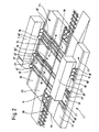
- the loading lines 5, 6 have for loading devices 9, 10, each loading device with a plurality of loading carriages 11, 11 ', 12, 12', 13, 13 ', 14, 14' is equipped.
- each loading device with a plurality of loading carriages 11, 11 ', 12, 12', 13, 13 ', 14, 14' is equipped.
- the movable loading carriages 11 to 14 'of the loading devices 9, 10 with corresponding formed on the frame 15 of the rail vehicle 8, channel-like depressions 16th '16'.
- Fig. 2 shows a second possible embodiment of a device 17 according to the invention, which in each case a Rangierbahn 21, 22 for forming the loading areas 23, 24 to each of the rail track 18 extending load paths 19, 20 has.
- the Rangierbahnen 21, 22 is achieved in particular a shortened loading and unloading, as to be loaded, inter alia, designed as a semi-trailer transport container 25 or semitrailer 5 with advantage by means of the Rangierbahnen 21, 22 formed transport devices 26, 27 targeted leaves.
- the Transport means 26, 27 have transport trolleys 28, 28 ', 29, 29', 29 ", 30, 30 ', 31, 31', 32, 32 ', 33, 33', 33", 34, 34 ', 35, 35 ', on the transport means 26 of the transport container 25 during loading initially by at least the transport means 26 forming dolly 29 ", 30, 30', 31, 31 'above the invisible loading carriage 11', 12, 12 'of the loading device 9 is positioned Thereafter, the transport container 25 to be displaced is taken over by the loading carriages 11 ', 12, 12' and set down directly on the loading surface 36 of the rail vehicle 8. For unloading the transport container, the handling steps are reversed, but the transfer is now effected by the loading carriages 13 '.
- a loading carriage 11 'of the loading carriages 11 to 14' used, inter alia, for forming a loading device 9, 10 is illustrated, the roughly parallelepiped frame 37 thereof being equipped with a large number of rollers 38 to 40.
- the frame 37 of the loading carriage is coupled to a hydraulic cylinder, not shown, by means of which the displacement movement is made from the loading road 5, 6, 19, 20 to the rail vehicle 8 and from the rail vehicle 8 to the loading road 5, 6, 19, 20 becomes.
- the loading carriage furthermore has a lifting device 41 with at least two lifting cylinders 42, 43, lifting plates 45, 46 forming with the aid of the at least partial surfaces of the contact surface 44 of the loading carriage 11 to 14 '.
- this illustrated loading carriage 11 ' is equipped with at least one pivotably articulated lifting element 47, 48, which is also part of the lifting device 41 and attacks in connection with the loading of the semi-trailer 25 in the coupling region and this securely supported during loading.
- this illustrated loading carriage 11 ' is equipped with at least one pivotably articulated lifting element 47, 48, which is also part of the lifting device 41 and attacks in connection with the loading of the semi-trailer 25 in the coupling region and this securely supported during loading.
- only one of the loading carriages 11 to 14 'of each loading device 9, 10 is equipped in a loading line 5, 6, 19, 20 with such pivotable lifting elements 47, 48.
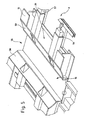
- FIG. 4 shows a detailed view of a arranged in the Rangierbahn 21, 22 transport 26, 27 to illustrate the structure and its operation.
- Each transporting device 26, 27 has two transport carriages 28 to 35 'which are held movable at a distance parallel to one another and between which a height-adjustable mounting plate 49 is arranged.
- Fig. 5 shows a perspective detailed view of a receiving area 55 for an axle, for example, a transport container of the rail vehicle 8 to illustrate its structure.
- the frame 15 of the rail vehicle 8 has in particular with the loading carriage 11 to 14 'of the loading devices 9, 10 (FIG. Fig. 1 to 3 ) corresponding, channel-like depressions 16, 16 ', in which a respective loading carriage for settling or receiving a example to be loaded transport container 25 is moved.
- securing profiles 56, 57 are moved on both sides of the wheels, by means of which at the same time a load securing and an advantageous stiffening of the frame of the rail vehicle 8 in a respective receiving area 55 is achieved.
- the receiving area 55 has in particular adapted to the shape of the wheels, concave support surfaces 58, 59 on.
Landscapes
- Engineering & Computer Science (AREA)
- Transportation (AREA)
- Mechanical Engineering (AREA)
- Loading Or Unloading Of Vehicles (AREA)
- Devices For Checking Fares Or Tickets At Control Points (AREA)
Abstract
Description
Die Erfindung bezieht sich auf ein Verfahren zum Auf- und Abladen von zumindest einem verfahrbaren, Güter aufnehmenden Transportbehälter eines Straßenfahrzeuges auf ein und von einem Schienenfahrzeug. Die Erfindung bezieht sich auch auf eine Vorrichtung zum Auf- und Abladen von zumindest einem fahrbaren, Güter aufnehmenden Transportbehälter eines Schlenenfahrzeuges auf ein und von einem Schienenfahrzeug, mit zumindest einem Ladebereich neben dem Schienenstrang für das Schienenfahrzeug, wobei der Ladebereich wenigstens eine Verladeeinrichtung für den mindestens einen zu versetzenden Transportbehälter aufweist.The invention relates to a method for loading and unloading at least one movable, goods receiving transport container of a road vehicle to and from a rail vehicle. The invention also relates to a device for loading and unloading at least one mobile, goods receiving transport container of a towing vehicle on and off a rail vehicle, with at least one loading area adjacent to the rail track for the rail vehicle, wherein the loading area at least one loading device for the at least having a transport container to be offset.
Bekannte Verfahren und Vorrichtungen werden eingesetzt, um Straßenfahrzeuge, wie zum Beispiel Personenkraftwagen, oder einen mittels eines Straßenfahrzeuges bewegten Transportbehälter, insbesondere einen Sattelauflieger, auf ein Schienenfahrzeug zu verladen. Damit soll insbesondere die Verlagerung von Teilen des Verkehrs, vornehmlich des Güterverkehrs, über weite Strecken auf die Schiene erreicht und somit eine Entlastung des Straßennetzes bewirkt werden. Dabei ist an den jeweiligen Be-und Entladeorten ein relativ einfacher Umschlag von der Straße auf die Schiene bzw. von der Schiene auf die Straße sicherzustellen.Known methods and devices are used to load road vehicles, such as passenger cars, or a transport container moved by means of a road vehicle, in particular a semi-trailer, onto a rail vehicle. This should in particular the relocation of parts of the traffic, especially of freight, over long distances to reach the rail and thus a relief of the road network can be effected. It is to ensure at the respective loading and unloading a relatively simple transfer from the road to the rail or from the rail to the road.
Aus der
In der
Der Erfindung liegt die Aufgabe zugrunde, ein Verfahren und eine Vorrichtung vorbezeichneter Gattung dahingehend zu verbessern, dass das Verladen von zumindest Transportbehältern auf vereinfachte Weise und somit in kürzerer Zeit erfolgen kann.The object of the invention is to improve a method and a device of the generic type described above in such a way that the loading of at least transport containers can take place in a simplified manner and thus in a shorter time.
Die Lösung der Aufgabe erfolgt erfindungsgemäß durch ein Verfahren mit den Merkmalen des Patentanspruches 1 und durch eine Vorrichtung mit den Merkmalen des Patentanspruches 5. Vorteilhafte Weiterbildungen und Ausgestaltungen der Erfindung sind in den jeweiligen Unteransprüchen angegeben.The object is achieved by a method with the features of claim 1 and by a device having the features of
Es ist ein Verfahren zum Auf und Abladen von zumindest einem fahrbaren, Güter aufnehmenden Transportbehälter eines Straßenfahrzeuges auf ein und von einem Schienenfahrzeug vorgesehen, bei dem der zumindest eine Transportbehälter zu einer Verladeeinrichtung wenigstens einer abschnittsweise entlang des Schienenstranges angeordneten Ladestraße in Position gebracht wird, der mindestens eine Transportbehälter mittels der Verladeeinrichtung angehoben, und der Transportbehälter aus einer Position neben dem Schienenfahrzeug in eine Position oberhalb des Schienenfahrzeuges bewegt wird, und dann der Transportbehälter in Aufnahmen am Schienenfahrzeug abgesenkt und die Verladeeinrichtungen in ihre Grundstellung in der Ladestraße zurückbewegt wird. Beim Entladen des Schienenfahrzeuges werden die Umschlagschritte umgekehrt abgewickelt. Demzufolge wird die Verladeeinrichtung aus ihrer Grundstellung der Ladestraße unterhalb des Transportbehälters bewegt und hebt diesen vom Schienenfahrzeug an. Dann wird der Transportbehälter aus der Position oberhalb des Schienenfahrzeuges in eine Position neben dem Schienenfahrzeug bewegt und der Transportbehälter auf der Ladestraße durch Absenken der Verladeeinrichtung abgesetzt.A method is provided for loading and unloading at least one mobile goods receiving transport container of a road vehicle onto and from a rail vehicle, in which the at least one transport container is brought into position to a loading device of at least one loading road arranged in sections along the rail track a transport container is lifted by means of the loading device, and the transport container is moved from a position next to the rail vehicle to a position above the rail vehicle, and then lowered the transport container in recordings on the rail vehicle and the loading devices is moved back to its normal position in the loading road. When unloading the rail vehicle, the handling steps are reversed handled. As a result, the loading device is moved from its basic position of the loading road below the transport container and lifts it from the rail vehicle. Then, the transport container is moved from the position above the rail vehicle to a position adjacent to the rail vehicle and the transport container placed on the loading road by lowering the loading device.
Mit einem derartig erfindungsgemäßen Verfahren lassen sich einzelne, fahrbare Transportbehälter sowie auch zum Beispiel ein kompletter Sattelzug, bestehend aus einer Sattelzugmaschine und einem Sattelauflieger, vorteilhaft einfach an einer beliebigen, freien Position auf den Zug verladen. Aufwendige Auf bzw. Abladevorgänge durch das Koppeln der beiderseits des Schienenstranges angeordneten Verladeeinrichtungen, wobei ein synchrones Ab- und Aufladen auf beiden Seiten des Schienenfahrzeuges nicht möglich ist, sind vorteilhaft vermieden. Mit dem erfindungsgemäßen Verfahren lassen sich zudem die Verweilzeiten der Züge an einer Umladestation mit Vorteil verringern. Zum Positionieren des Transportbehälters oder des Lastkraftwagens zur Verladeeinrichtung wird dieser beispielsweise auf der Ladestraße in eine vorbestimmte Position verfahren und bevorzugt parallel zum Schienenstrang abgestellt. Mit Hilfe der Verladeeinrichtung wird dann der Transportbehälter quer zum Schienenstrang angehoben und anschließend wird die Verladeeinrichtung zusammen mit dem Transportbehälter quer zum Schienenstrang auf einer waagerecht verlaufenden Ebene von der Ladestraße auf das Schienenfahrzeug bewegt. Das Schienenfahrzeug weist insbesondere Vertiefungen in der Ladefläche auf, in die den Transportbehälter aufnehmende Ladeschlitten der Verladeeinrichtung eingeschoben werden, so dass der Transportbehälter mit Vorteil auf einem relativ niedrigen Niveau auf dem Schienenfahrzeug abgesetzt werden kann. Nachdem der Transportbehälter in speziellen Aufnahmen an der Ladefläche des Schienenfahrzeuges abgesetzt ist, so dass die Verladeeinrichtung wieder freigängig ist, wird die Verladeeinrichtung in ihre Grundstellung in der Ladestraße zurückbewegt.With such a method according to the invention, individual, transportable transport containers as well as, for example, a complete semitrailer, consisting of a semitrailer tractor and a semitrailer, can advantageously be loaded onto the train at any desired free position. Elaborate loading or unloading by coupling the arranged on both sides of the rail line loading equipment, with a synchronous unloading and recharging on both sides of the rail vehicle is not possible, are advantageously avoided. With the method according to the invention, in addition, the residence times of the trains at a transfer station with advantage reduce. For positioning the transport container or the truck to the loading device this is moved, for example, on the loading road in a predetermined position and preferably parked parallel to the rail track. With the help of the loading device then the transport container is lifted transversely to the rail track and then the loading device is moved together with the transport container transversely to the rail track on a plane extending horizontally from the loading road to the rail vehicle. In particular, the rail vehicle has depressions in the loading area into which the loading carriages of the loading device receiving the transport container are pushed, so that the transport container can advantageously be set down at a relatively low level on the rail vehicle. After the transport container is placed in special shots on the back of the rail vehicle, so that the loading device is free again, the loading device is moved back to its normal position in the loading road.
Nach einer vorteilhaften Weiterbildung ist vorgesehen, dass der Transportbehälter vor dem in Position bringen auf der Ladestraße auf einer etwa parallel zur Ladestraße verlaufenden Rangierbahn abgestellt wird. Durch das Abstellen des zumindest eines Transportbehälters oder Lastkraftwagens auf der Rangierbahn erfolgt das Rangieren nicht mehr auf der Ladestraße, wodurch die Abstände zwischen den zu verladenden Transportbehältern auf der Ladestraße relativ gering gehalten werden können. Zudem ist ein ständiges Überfahren der Verladeeinrichtung in der Ladestraße vermieden. Das Umsetzen des Transportbehälters von der Rangierbahn auf die Ladestraße kann dabei mit geeigneten Mitteln ebenfalls in Querrichtung zur Erstreckung der Ladestraße vorgenommen werden.According to an advantageous development, it is provided that the transport container is parked in front of the position on the loading road on a running approximately parallel to the loading road Rangierbahn. By parking the at least one transport container or truck on the maneuvering maneuvering is no longer on the loading road, whereby the distances between the transport containers to be loaded on the loading road can be kept relatively low. In addition, a constant driving over the loading device in the loading road is avoided. The transfer of the transport container from the shunting track on the loading road can also be made with suitable means in the transverse direction to the extension of the loading road.
Nach dem Abstellen des Transportbehälters auf der Rangierbahn wird durch Absenken von Teilbereichen der Aufstandsfläche der Rangierbahn der Transportbehälter, insbesondere dessen Räder aufweisenden Achsen, In eine Flucht mit der Verladeeinrichtung der Ladestraße gebracht. Durch das Absenken von Teilbereichen der Aufstandsfläche ist über die sich dabei ausbildenden Flanken der in der Höhe unveränderlichen Seitenbereiche zu beiden Seiten der abgesenkten Teilflächen eine selbsttätige Ausrichtung des Transportbehälters bewirkt, Eine in diesem Zusammenhang verwendete, höhenverstellbare Aufstellplatte zum Absenken des Transportbehälters weist eine Breite auf, die etwa dem halben Durchmesser des darauf aufstehenden Rades entspricht, Durch das gleichzeitig beim Ablassen des Transportbehälters erfolgte Ausrichten, lässt sich der Verladevorgang auf vorteilhafte Weise automatisieren und damit weiter verbessern.After parking the transport container on the Rangierbahn is brought by lowering portions of the footprint of the Rangierbahn the transport container, in particular whose wheels having axes, in alignment with the loading device of the loading road. By lowering partial areas of the contact area, the side areas which are invariable in height are accessible via the flanks forming thereby An automatic adjustment of the transport container is effected on both sides of the lowered partial surfaces. A height-adjustable mounting plate for lowering the transport container used in this context has a width that corresponds approximately to half the diameter of the wheel resting thereon. By aligning the same when draining the transport container. the loading process can be automated in an advantageous manner and thus further improved.
Nach dem Ausrichten wird der Transportbehälter mittels einer an der Rangierbahn vorgesehenen Transporteinrichtung von der Rangierbahn in eine vorgegebene Position oberhalb der Verladeeinrichtung bewegt. Das Umsetzen zwischen den verschiedenen Abschnitten des Ladebereiches ist dadurch auf vorteilhaft einfache Weise gewährleistet, wobei der zu verladende Transportbehälter oder Lastkraftwagen unmittelbar oberhalb der Verladeeinrichtung in Position gebracht ist. Somit kann der von der Verladeeinrichtung weiter auf das Schienenfahrzeug zu versetzende Transportbehälter durch Hochfahren einer Hubeinrichtung der Verladeeinrichtung von dieser übernommen werden, so dass die Transporteinrichtung wieder frei beweglich ist und ihrerseits in ihre Grundstellung in die Rangierbahn zurückbewegt werden kann. Die Transporteinrichtung führt dabei vorzugsweise eine ausschließlich lineare Bewegung quer zur Ladestraße auf einer waagerecht verlaufenden Ebene aus.After alignment, the transport container is moved by means of a provided on the Rangierbahn transport means of the Rangierbahn in a predetermined position above the loading device. The transfer between the various sections of the loading area is thereby ensured in an advantageously simple manner, wherein the transport container or truck to be loaded is brought into position immediately above the loading device. Thus, the transport container to be displaced further from the loading device to the rail vehicle can be taken over by raising a lifting device of the loading device, so that the transport device is free to move again and in turn can be moved back into its basic position in the Rangierbahn. The transport device preferably performs an exclusively linear movement transversely to the loading road on a horizontally extending plane.
Bei einer Vorrichtung zum Auf- und Abladen von zumindest einem fahrbaren, Güter aufnehmenden Transportbehälter eines Straßenfahrzeuges auf ein und von einem Schienenfahrzeug, mit zumindest einem Ladebereich neben dem Schienenstrang für das Schienenfahrzeug, wobei der Ladebereich wenigstens eine Verladeeinrichtung für den mindestens einen zu versetzenden Transportbehälter aufweist, für die selbstständiger Schutz beantragt wird, ist erfindungsgemäß vorgesehen, dass die Verladeeinrichtung mindestens einen Ladeschlitten aufweist, welcher quer zum Schienenstrang zwangsbeweglich geführt ist, wobei der Ladeschlitten mit einer am Schienenfahrzeug vorgesehenen Aufnahme korrespondiert, und wobei der Ladeschlitten mit einer Hubeinrichtung zum Anheben und Absenken des Transportbehälters ausgerüstet ist.In a device for loading and unloading at least one mobile goods receiving transport container of a road vehicle on and off a rail vehicle, with at least one loading area adjacent to the rail track for the rail vehicle, wherein the loading area has at least one loading device for the at least one transport container to be displaced , is requested for the independent protection, the invention provides that the loading device has at least one loading carriage, which is guided positively movable transversely to the rail track, wherein the loading carriage corresponds to a provided on the rail vehicle recording, and wherein the loading carriage with a lifting device is equipped for raising and lowering the transport container.
Mittels einer derartig erfindungsgemäß ausgebildeten Vorrichtung lässt sich der Verladevorgang sowohl eines einzelnen Transportbehälters als auch eines gesamten Lastkraftwagens, wie zum Beispiel einem Sattelzug, auf zum Beispiel ein Schienenfahrzeug, auf einfache Weise und somit in relativ kurzer Zeit umsetzen. Der Ladeschlitten korrespondiert insbesondere mit einer Vertiefung am Schienenfahrzeug, welche, von der Unterseite des Schienenfahrzeuges ausgehend, stets in einem relativ geringen Abstand ausgebildet ist, um eine vorteilhaft große Ladehöhe zu gewährleisten, so dass das zulässige Lichtraumprofil eingehatten ist. Der Ladeschlitten ist dabei über eine Geradführung in der Ladestraße aufgenommen und weist mehrere Rollen für eine reibungsarme Bewegung in der Führung auf. Die ebenfalls als Führung für den Ladeschlitten ausgebildete Vertiefung am Schienenfahrzeug ist des Weiteren in einem vorbestimmten Bereich mit Vorteil als Aufnahme ausgestaltet, derart dass darin die Räder einer Achse des Transportbehälters zentrierend aufgenommen bzw. gehalten sind. Der Ladeschlitten ist mit einer Hubeinrichtung ausgerüstet, über die während des Verladevorganges zum einen die Freigängigkeit des Transportbehälters und zum anderen nach dem Absetzen des Transportbehälters der Kontakt zwischen dem Ladeschlitten und den Rädern des Transportbehälters aufgehoben ist und der Ladeschlitten wieder unabhängig vom Transportbehälter verfahren werden kann.By means of such a device according to the invention, the loading operation of both a single transport container and an entire truck, such as a tractor-trailer, for example, a rail vehicle, can be implemented in a simple manner and thus in a relatively short time. The loading carriage corresponds in particular with a recess on the rail vehicle, which, starting from the underside of the rail vehicle, is always formed at a relatively small distance in order to ensure an advantageously large loading height, so that the permissible clearance profile is covered. The loading carriage is received via a straight guide in the loading road and has several roles for a low-friction movement in the guide. The also formed as a guide for the loading carriage recess on the rail vehicle is further configured in a predetermined area with advantage as a receptacle, so that therein the wheels of an axis of the transport container are accommodated or held centering. The loading carriage is equipped with a lifting device, on the one hand, the free movement of the transport container and on the other hand after discontinuation of the transport container, the contact between the loading carriage and the wheels of the transport container is lifted and the loading carriage can be moved again independently of the transport container.
Mit Vorteil weist die Verladeeinrichtung mehrere Ladeschlitten auf, welche zumindest bestimmten Rädern aufweisenden Achsen des Transportbehälters zugeordnet sind. Zur Ausbildung der Verladeeinrichtung kommen bevorzugt vier Ladeschlitten zur Anwendung, wobei zwei der Ladeschlitten zum Beispiel der Vorder- und Hinterachse einer gegebenenfalls mit zu verladenden Zugmaschine eines Sattelzuges und die zwei anderen Ladeschlitten zwei der häufig drei Achsen des Sattelaufliegers zugeordnet sind. Darüber ist stets ein gleichmäßiges Anheben des insbesondere zu versetzenden Sattelzuges über seine Gesamtlänge gegeben. Ebenso wie das Anheben erfolgt auch gleichzeitig die Versatzbewegung von der Ladestraße auf das Schienenfahrzeug an allen vier Ladeschlitten gleichzeitig. Die Versatzbewegung der Ladeschlitten von der Ladestraße auf das Schienenfahrzeug kann beispielsweise mit Hilfe von Kettenantrieben erfolgen, welche untereinander synchronisiert sind.Advantageously, the loading device has a plurality of loading carriages, which are associated with at least certain wheels having axes of the transport container. For the formation of the loading device preferably four loading carriage are used, wherein two of the loading slide, for example, the front and rear axles of a possibly to be loaded tractor of a semitrailer and the other two loading carriages two of the often three axes of the semitrailer are assigned. In addition, there is always a uniform lifting of the particular to be displaced tractor over its entire length. As well as the lifting takes place at the same time the displacement movement of the loading road on the rail vehicle on all four loading carriages at the same time. The displacement movement of the loading carriages from the loading road to the rail vehicle can be effected for example by means of chain drives, which are synchronized with one another.
Jeder Ladeschlitten ist vorzugsweise in einer kanalartigen Vertiefung einer den Ladebereich wenigstens teilweise ausbildenden Ladestraße aufgenommen, wobei die Aufstellflächen der Ladeschlitten insbesondere auf gleichem Niveau mit der Oberfläche der beispielsweise aus einem Betonwerkstoff gefertigten Ladestraße angeordnet sind. Demzufolge können bei nur einer Ladestraße neben dem Schienenstrang der oder die zu verladenden Transportbehälter bzw. Sattel- oder Gliederzüge über die in die Ladestraße eingelassenen Ladeschlitten fahren. Speziell bei nur einer einspurigen Ladestraße mit mehreren in einer Reihe hintereinander angeordneten Verladeeinrichtungen für insbesondere das gleichzeitige Verladen auf einen aus einer Vielzahl von Schienenfahrzeugen gebildeten Zug, ist es zur Gewährleistung eines zügigen Verladevorganges zwingend, dass die zu verladenden Lastkraftwagen bzw. Transportbehälter problemlos über die Verladeeinrichtungen fahren können. Die Ladestraße kann sowohl auf nur einer Seite des Schienenfahrzeuges als auch auf beiden Seiten entlang des Schienenstranges angeordnet sein.Each loading carriage is preferably accommodated in a channel-like depression of a loading area which at least partially forms the loading area, the installation areas of the loading carriages being arranged in particular at the same level as the surface of the loading street made of a concrete material, for example. Consequently, with only one loading road next to the rail track, the transport container or saddle or articulated trains to be loaded can travel over the loading carriages let into the loading road. Especially with only one single-lane loading road with several in a row successively arranged loading facilities for particular simultaneous loading on a train formed from a variety of rail vehicles, it is imperative to ensure a speedy loading that the trucks to be loaded or transport containers easily on the loading equipment can drive. The loading road can be arranged both on only one side of the rail vehicle and on both sides along the rail track.
Darüber hinaus ist vorgesehen, dass etwa parallel über entlang eines Abschnittes des Schienenstranges wenigstens eine Ladestraße und eine entlang der Ladestraße verlaufende Rangierbahn vorgesehen sind. Die Ausbildung des Ladebereiches aus einer Ladestraße und einer Rangierbahn hat den Vorteil, dass das Befahren der Ladestraße durch die zu verladenden Transportbehälter nicht in einer bestimmten Reihenfolge erfolgen muss. Die Zuordnung der verschiedenen Verladeplätze kann in beliebiger Abfolge vorgenommen werden, beispielsweise in Bezug auf die individuelle Ankunft der Transportbehälter am Verladeterminal. Ladestraße und Rangierbahn können insbesondere identische Fahrspurbreiten aufweisen, wobei die beiden Spuren des Verladebereiches stets eine ausreichende Mindestbreite für ein gefahrloses Vorbeifahren eines noch zu positionierenden Lastkraftwagen an zum Beispiel einen bereits auf der Ladestraße positionierten Transportbehälter aufweisen. Es ist ebenfalls denkbar, neben der Ladestraße und der Rangierbahn eine weitere, als Fahrstraße ausgebildete Spur vorzusehen.In addition, it is provided that approximately parallel over along a portion of the rail track at least one loading road and along the loading road running Rangierbahn are provided. The formation of the loading area from a loading road and a maneuvering track has the advantage that driving on the loading road through the transport containers to be loaded does not have to take place in a particular order. The assignment of the various loading locations can be made in any order, for example, in relation to the individual arrival of the transport container at the loading terminal. Loading road and Rangierbahn can in particular have identical lane widths, the two lanes of the loading always a sufficient minimum width for a safe driving past a still to be positioned truck to, for example, already positioned on the loading road transport container exhibit. It is also conceivable, in addition to the loading road and the Rangierbahn provide another trained as a route track.
Nach einer Weiterbildung der Erfindung ist vorgesehen, dass die Rangierbahn zumindest mit Transportwagen zum quergerichteten Umsetzen des Transportbehälters auf die Ladestraße ausgerüstet ist. Mit Hilfe der Transportwagen erfolgt ein relativ einfaches Umsetzen eines zuvor auf der Rangierbahn zu den Verladeeinrichtungen in der Ladestraße positionierten Transportbehälters von der Ranglerbahn auf die Ladestraße. Um einen störungsfreien Verladevorgang zu gewährleisten, weist die Rangierbahn zur Ladestraße bevorzugt ein höheres Niveau auf. Durch den Absatz zwischen Ladestraße und Rangierbahn lassen sich die Transportwagen problemlos oberhalb der Aufstandsfläche der Ladestraße verfahren. Es ist ebenfalls denkbar, die Aufstandsflächen der Ladestraße und der Rangierbahn auf einem Höhenniveau auszubilden, wobei dann in der Ladestraße Führungsbahnen für die Transportwagen vorzusehen sind, welche beiderseits neben einem in der Ladestraße eingelassenen Ladeschlitten auszubilden sind. Gleichzeitig weist jeder Transportwagen Mittel zum Ausrichten der Räder einer Achse eines insbesondere aufzuladenden Transportbehälters auf, um ein geziettes Ausrichten zu den Ladeschlitten der Ladestraße zu gewährleisten.According to a development of the invention it is provided that the Rangierbahn is equipped at least with trolley for transverse transposition of the transport container on the loading road. With the help of the trolley is a relatively simple implementation of a previously positioned on the Rangierbahn to the loading equipment in the loading road transport container from the Ranglerbahn done on the loading road. In order to ensure trouble-free loading, the shunting track to the loading road preferably has a higher level. Due to the heel between the loading road and the shunting track, the transport vehicles can be easily moved above the footprint of the loading road. It is also conceivable to form the footprint of the loading road and the Rangierbahn at a height level, then in the loading road guideways are provided for the trolley, which are to be formed on either side of a recessed in the loading road loading carriage. At the same time, each trolley has means for aligning the wheels of an axle of a particular transport container to be charged in order to ensure a ziettes alignment with the loading carriage of the loading road.
Diesbezüglich ist erfindungsgemäß zwischen zwei einander zugeordneten Transportwagen der Rangierbahn eine in der Höhe verstellbare Aufstellplatte vorgesehen. Mittels der Aufstellplatte lässt sich der fahrbare Transportbehälter bzw. der Lastkraftwagen zwischen den jeweiligen Transportwagen absenken, wodurch die Räder sich automatisch zu den sich bildenden Kantenbereichen ausrichten. Bevorzugt weist jeder Transportwagen schwenkbar angelenkte Plattenkörper zur Ausbildung mindestens eines Abschnitts einer etwa senkrecht zum Radumfang stehenden Aufstandsfläche auf. Diese korrespondieren mit der in der Höhe verstellbaren Aufstellplatte derart, dass sich die Plattenkörper automatisch zum Mittenbereich hin neigen, wenn die Aufstellplatte nach unten verfahren wird. Ebenso werden die Plattenkörper wieder in eine waagerechte Ausrichtung gebracht, wenn die Aufstellplatte in ihre obere Position zurückgefahren wird. Die schwenkbaren Plattenkörper an den Transportwagen weisen dabei bevorzugt mindestens die Breite eines zu versetzenden Radsatzes auf. Der den Stützen eines zu verladenden Transportbehälters zugeordnete Transportwagen ist jedoch mit keinen schwenkbaren Plattenkörpem ausgerüstet.In this regard, according to the invention is provided between two associated trolley of Rangierbahn an adjustable in height mounting plate. By means of the mounting plate, the mobile transport container or the truck can be lowered between the respective trolley, whereby the wheels are automatically aligned to the forming edge areas. Preferably, each trolley pivotally hinged plate body to form at least a portion of a standing approximately perpendicular to the wheel circumference contact surface. These correspond with the height-adjustable mounting plate in such a way that the plate body automatically inclines toward the central region, when the mounting plate is moved down. Similarly, the plate body are brought back into a horizontal orientation when the mounting plate is moved back to its upper position. The swivel plate body the trolley preferably have at least the width of a wheel set to be offset. However, the supports of a transport container to be loaded associated dolly is equipped with no swivel Plattenkörpem.
Nach einer anderen Weiterbildung der Erfindung ist vorgesehen, dass der Ladeschlitten und der Transportwagen für eine horizontale Verstellbewegung waagerecht ausgerichtete Arbeitszylinder aufweisen, und dass die Hubeinrichtung der Ladeschlitten und die höhenverstellbare Auflagerplatte mit senkrecht ausgerichteten Hubzylindern ausgerüstet sind. Durch den Einsatz insbesondere hydraulisch betriebener Verstellantriebe ist eine vorteilhafte Möglichkeit zur Umsetzung der in horizontaler und vertikaler Richtung vorzunehmenden Verstellbewegungen gegeben. Hydraulische Antriebe haben des Weiteren den Vorteil, dass mittels dieser relativ hohe Kräfte erzeugt werden können, welche zum Bewegen der üblicherweise mehrere Tonnen schweren Transportbehälter und Lastkraftwagen benötigt werden. Anstelle eines Hydraulikantriebes für die horizontal zu bewegenden Ladeschlitten kann gegebenenfalls auch ein Elektromotor Anwendung finden, der beispielsweise über einen Kettenantrieb mit einem insbesondere auf Rollen geführten Ladeschlitten und Transportwagen verbunden sein kann.According to another embodiment of the invention, it is provided that the loading slide and the trolley for horizontal adjustment have horizontally oriented working cylinder, and that the lifting device of the loading slide and the height-adjustable support plate are equipped with vertically oriented lifting cylinders. By using in particular hydraulically operated adjusting drives, an advantageous possibility for implementing the adjustment movements to be made in the horizontal and vertical directions is provided. Furthermore, hydraulic drives have the advantage that relatively high forces can be generated by means of these, which are required for moving the transport containers and trucks, which are usually several tons in weight. Instead of a hydraulic drive for the horizontally moving loading carriage may optionally also find an electric motor application, which may be connected, for example via a chain drive with a guided in particular on rollers loading carriage and dolly.
Ausführungsbeispiele der Erfindung, aus denen sich weitere erfinderische Merkmale ergeben, sind in der Zeichnung dargestellt. Es zeigen:
-
Fig. 1 : eine perspektivische Ansicht eines ersten Ausführungsbeispiels einer erfindungsgemäßen Vorrichtung; -
Fig. 2 : eine Ansicht eines zweiten Ausführungsbeispiels einer erfindungsgemäßen Vorrichtung; -
Fig. 3 : eine perspektivische Ansicht eines Ladeschlittens einer Verladeeinrichtung; -
Fig. 4 : eine Ansicht einer Transporteinrichtung, und -
Fig. 5 : eine perspektivische Ansicht eines Aufnahmebereiches für eine Achse am Schienenfahrzeug.
-
Fig. 1 a perspective view of a first embodiment of a device according to the invention; -
Fig. 2 a view of a second embodiment of a device according to the invention; -
Fig. 3 a perspective view of a loading carriage of a loading device; -
Fig. 4 : a view of a transport device, and -
Fig. 5 : A perspective view of a receiving area for an axle on the rail vehicle.
Mit 1 ist eine Vorrichtung zum Auf und Abladen von zumindest einem fahrbaren, Güter aufnehmenden Transportbehälter eines Straßenfahrzeuges auf ein und von einem Schienenfahrzeug bezeichnet, mit Hilfe dem der Umschlag beispielsweise eines Sattelzuges oder auch nur dem Sattelauflieger des Sattelzuges auf einen und von einem speziell dafür ausgebildeten Schienenfahrzeug ermöglicht. Die Vorrichtung 1 weist bevorzugt beiderseits parallel entlang eines Schienenstranges 2 zwei Ladebereiche 3, 4 mit jeweils einer Ladestraße 5, 6 auf, wobei ein Sattelzug 7 üblicherweise von der einen Ladestraße 5 auf das als Eisenbahnwaggon ausgebildete Schienenfahrzeug 8 verladen und vom Schienenfahrzeug 8 auf die andere Ladestraße 6 entladen wird. Neben dem Schienenstrang kann aber auch nur ein Ladebereich ausgebildet sein, über den sowohl das Auf- und Abladen erfolgt. Die Ladestraßen 5, 6 weisen dafür Verladeeinrichtungen 9, 10 auf, wobei jede Verladeeinrichtung mit mehreren Ladeschlitten 11, 11', 12, 12', 13, 13', 14, 14' ausgerüstet ist. Um eine relativ niedrige Ladehöhe des Sattelzuges 7 auf dem Schienenfahrzeug 8 und die damit verbundene Einhaltung des maximal zulässigen Lichtraumprofiles zu gewährleisten, korrespondieren die verfahrbaren Ladeschlitten 11 bis 14' der Verladeeinrichtungen 9, 10 mit entsprechenden am Rahmengestell 15 des Schienenfahrzeuges 8 ausgebildeten, kanalartigen Vertiefungen 16, 16'.1 with a device for loading and unloading of at least one mobile, goods receiving transport container of a road vehicle on and from a rail vehicle is called, with the help of the envelope, for example, a semitrailer or even only the semitrailer of the semitrailer on one and by a specially trained Rail vehicle allows. The device 1 preferably has on both sides in parallel along a
In
Claims (12)
der zumindest eine Transportbehälter (25) zu einer Verladeeinrichtung (9, 10) wenigstens einer abschnittsweise entlang des Schienenstranges (2, 18) angeordneten Ladestraße (5, 6, 19, 20) in Position gebracht wird,
der mindestens eine Transportbehälter (25) mittels der Verladeeinrichtung (9, 10) angehoben und der Transportbehälter (25) aus einer Position neben dem Schienenfahrzeug (8) in eine Position oberhalb des Schienenfahrzeuges (8) bewegt wird,
dann der Transportbehälter (25) in Aufnahmen am Schienenfahrzeug (8) abgesenkt und die Verladeeinrichtung (9, 10) in ihre Grundstellung In der Ladestraße (5, 6, 19, 20) zurückbewegt wird,
beim Entladen des Schienenfahrzeuges (8) laufen die Umschlagschritte umgekehrt ab.A method for loading and unloading at least one wheeled, goods receiving transport container of a road vehicle to and from a rail vehicle, wherein
the at least one transport container (25) being brought into position to a loading device (9, 10) of at least one loading path (5, 6, 19, 20) arranged in sections along the rail track (2, 18),
the at least one transport container (25) is lifted by means of the loading device (9, 10) and the transport container (25) is moved from a position next to the rail vehicle (8) to a position above the rail vehicle (8),
then the transport container (25) lowered in recordings on the rail vehicle (8) and the loading device (9, 10) is moved back into its basic position in the loading road (5, 6, 19, 20),
when unloading the rail vehicle (8) the Umschlagschritte run in reverse.
dadurch gekennzeichnet,
dass die Verladeeinrichtung (9, 10) mindestens einen Ladeschlitten (11 bis 14') aufweist, welcher quer zum Schienenstrang (2) zwangsbeweglich geführt ist, wobei der Ladeschlitten (11 bis 14') mit einer am Schienenfahrzeug (8) vorgesehenen Aufnahme (16, 16') korrespondiert, und wobei der Ladeschlitten (11 bis 14') mit mindestens einer Hubeinrichtung (41) zum Anheben und Absenken des Transportbehälters (25) ausgerüstet ist.Device for loading and unloading at least one mobile goods receiving transport container of a road vehicle onto and from a rail vehicle, having at least one loading area next to the rail track for the rail vehicle, the loading area having at least one loading device for the at least one transport container to be displaced,
characterized,
in that the loading device (9, 10) has at least one loading carriage (11 to 14 ') which is guided so as to be movable transversely to the rail track (2), the loading carriage (11 to 14') being provided with a receptacle (16) provided on the rail vehicle (8) , 16 '), and wherein the loading carriage (11 to 14') is equipped with at least one lifting device (41) for raising and lowering the transport container (25).
Priority Applications (3)
| Application Number | Priority Date | Filing Date | Title |
|---|---|---|---|
| SI201131176A SI2384947T1 (en) | 2010-05-03 | 2011-05-03 | Method and device for loading goods traffic on to rails |
| PL11003599T PL2384947T3 (en) | 2010-05-03 | 2011-05-03 | Method and device for loading goods traffic on to rails |
| HRP20170819TT HRP20170819T1 (en) | 2010-05-03 | 2017-05-30 | Method and device for loading goods traffic on to rails |
Applications Claiming Priority (1)
| Application Number | Priority Date | Filing Date | Title |
|---|---|---|---|
| DE102010019002A DE102010019002A1 (en) | 2010-05-03 | 2010-05-03 | Method and device for loading freight transport by rail |
Publications (2)
| Publication Number | Publication Date |
|---|---|
| EP2384947A1 true EP2384947A1 (en) | 2011-11-09 |
| EP2384947B1 EP2384947B1 (en) | 2017-03-01 |
Family
ID=44260373
Family Applications (1)
| Application Number | Title | Priority Date | Filing Date |
|---|---|---|---|
| EP11003599.5A Active EP2384947B1 (en) | 2010-05-03 | 2011-05-03 | Method and device for loading goods traffic on to rails |
Country Status (5)
| Country | Link |
|---|---|
| EP (1) | EP2384947B1 (en) |
| DE (1) | DE102010019002A1 (en) |
| HR (1) | HRP20170819T1 (en) |
| PL (1) | PL2384947T3 (en) |
| SI (1) | SI2384947T1 (en) |
Cited By (7)
| Publication number | Priority date | Publication date | Assignee | Title |
|---|---|---|---|---|
| CN105035111A (en) * | 2015-07-26 | 2015-11-11 | 郭卫康 | Double-track device and method for horizontal and quick car transfer used for train |
| CN105059290A (en) * | 2015-07-26 | 2015-11-18 | 郭卫康 | Device and method for double-crawler transverse rapid transferring car |
| WO2018101883A1 (en) | 2016-12-04 | 2018-06-07 | Sidestacker Ab | A method and arrangement for loading a semi-trailer onto a railway wagon |
| IT201800003357A1 (en) * | 2018-03-08 | 2019-09-08 | Brentauto Di Renato Fassina E C S N C | Loading and unloading station for semi-trailers of articulated vehicles on / from railway. |
| CN110482275A (en) * | 2018-12-12 | 2019-11-22 | 广东天酿智能装备有限公司 | Handling support platform apparatus and its working method |
| WO2022234084A1 (en) * | 2021-05-07 | 2022-11-10 | MCS Vermögensverwaltungs Aktiengesellschaft | Method for forming a train |
| KR20230039216A (en) * | 2021-09-14 | 2023-03-21 | 한국기계연구원 | Transporting equipment and method for rail logistics piggyback wagon using moving trailer |
Families Citing this family (3)
| Publication number | Priority date | Publication date | Assignee | Title |
|---|---|---|---|---|
| DE202012006378U1 (en) | 2012-07-02 | 2012-08-20 | RLI - Rail Logistik Innovation GbR mbH (vertretungsberechtigte Gesellschafter: Hans-Wilhelm Peters, 79837 St. Blasien; Bruno Lichtnow, 26759 Hinte) | Railway wagons, in particular freight wagons for transporting road vehicles |
| CN107826584A (en) * | 2017-12-06 | 2018-03-23 | 中华全国供销合作总社郑州棉麻工程技术设计研究所 | A kind of cotton bale transport cart |
| CN116639158B (en) * | 2023-07-27 | 2023-10-17 | 今创集团股份有限公司 | Container moving device |
Citations (4)
| Publication number | Priority date | Publication date | Assignee | Title |
|---|---|---|---|---|
| FR2149314A1 (en) * | 1971-08-13 | 1973-03-30 | Mariage Georges | |
| DE3037031A1 (en) | 1980-10-01 | 1982-05-06 | Hans-Jürgen 5250 Engelskirchen Jung | Moving cars on and off railway wagon deck - involves transfer units moving cars transversely to rail track onto platform level with deck |
| EP1241118A2 (en) * | 2001-02-16 | 2002-09-18 | Siemag Transplan Gmbh | Method and device for loading and unloading palletized bulk goods from road vehicles onto railway trains and vice versa |
| DE102004040245A1 (en) | 2004-08-13 | 2006-02-23 | Frenzel-Bau Gmbh & Co. Kg | Cargo handling and transport system |
Family Cites Families (3)
| Publication number | Priority date | Publication date | Assignee | Title |
|---|---|---|---|---|
| DE1556705A1 (en) * | 1968-02-29 | 1970-01-15 | Weyhausen & Co Maschinenfabrik | Device for putting on, taking off and translating containers |
| DE4301019C2 (en) * | 1993-01-16 | 1995-04-20 | Erich Lang | Handling system for the horizontal handling of containers, trucks and the like between road and rail vehicles |
| DE10101891B4 (en) * | 2001-01-16 | 2008-11-13 | Weber Hydraulik Consulting | Loading and unloading system of vehicle units |
-
2010
- 2010-05-03 DE DE102010019002A patent/DE102010019002A1/en not_active Withdrawn
-
2011
- 2011-05-03 SI SI201131176A patent/SI2384947T1/en unknown
- 2011-05-03 EP EP11003599.5A patent/EP2384947B1/en active Active
- 2011-05-03 PL PL11003599T patent/PL2384947T3/en unknown
-
2017
- 2017-05-30 HR HRP20170819TT patent/HRP20170819T1/en unknown
Patent Citations (4)
| Publication number | Priority date | Publication date | Assignee | Title |
|---|---|---|---|---|
| FR2149314A1 (en) * | 1971-08-13 | 1973-03-30 | Mariage Georges | |
| DE3037031A1 (en) | 1980-10-01 | 1982-05-06 | Hans-Jürgen 5250 Engelskirchen Jung | Moving cars on and off railway wagon deck - involves transfer units moving cars transversely to rail track onto platform level with deck |
| EP1241118A2 (en) * | 2001-02-16 | 2002-09-18 | Siemag Transplan Gmbh | Method and device for loading and unloading palletized bulk goods from road vehicles onto railway trains and vice versa |
| DE102004040245A1 (en) | 2004-08-13 | 2006-02-23 | Frenzel-Bau Gmbh & Co. Kg | Cargo handling and transport system |
Cited By (14)
| Publication number | Priority date | Publication date | Assignee | Title |
|---|---|---|---|---|
| CN105035111A (en) * | 2015-07-26 | 2015-11-11 | 郭卫康 | Double-track device and method for horizontal and quick car transfer used for train |
| CN105059290A (en) * | 2015-07-26 | 2015-11-18 | 郭卫康 | Device and method for double-crawler transverse rapid transferring car |
| CN105059290B (en) * | 2015-07-26 | 2019-03-22 | 郭卫康 | A kind of method that double crawler belts laterally quickly transfer car |
| CN105035111B (en) * | 2015-07-26 | 2019-06-11 | 郭卫康 | A kind of device and method that double crawler belts that train uses laterally quickly transfer car |
| WO2018101883A1 (en) | 2016-12-04 | 2018-06-07 | Sidestacker Ab | A method and arrangement for loading a semi-trailer onto a railway wagon |
| US10815079B2 (en) | 2016-12-04 | 2020-10-27 | Sidestacker Ab | Method and arrangement for loading a semi-trailer onto a railway wagon |
| WO2019170585A1 (en) * | 2018-03-08 | 2019-09-12 | Brentauto Di Renato Fassina E C. S.N.C. | Station for loading and unloading semi-trailers of articulated lorries on/from the railway |
| IT201800003357A1 (en) * | 2018-03-08 | 2019-09-08 | Brentauto Di Renato Fassina E C S N C | Loading and unloading station for semi-trailers of articulated vehicles on / from railway. |
| CN110482275A (en) * | 2018-12-12 | 2019-11-22 | 广东天酿智能装备有限公司 | Handling support platform apparatus and its working method |
| WO2022234084A1 (en) * | 2021-05-07 | 2022-11-10 | MCS Vermögensverwaltungs Aktiengesellschaft | Method for forming a train |
| AT525096A4 (en) * | 2021-05-07 | 2022-12-15 | Mcs Vermoegensverwaltungs Ag | Procedure for forming a train |
| AT525096B1 (en) * | 2021-05-07 | 2022-12-15 | Mcs Vermoegensverwaltungs Ag | Procedure for forming a train |
| KR20230039216A (en) * | 2021-09-14 | 2023-03-21 | 한국기계연구원 | Transporting equipment and method for rail logistics piggyback wagon using moving trailer |
| KR102590808B1 (en) | 2021-09-14 | 2023-10-19 | 한국기계연구원 | Transporting equipment and method for rail logistics piggyback wagon using moving trailer |
Also Published As
| Publication number | Publication date |
|---|---|
| EP2384947B1 (en) | 2017-03-01 |
| SI2384947T1 (en) | 2017-07-31 |
| DE102010019002A1 (en) | 2011-11-03 |
| HRP20170819T1 (en) | 2017-08-11 |
| PL2384947T3 (en) | 2017-08-31 |
Similar Documents
| Publication | Publication Date | Title |
|---|---|---|
| EP2384947B1 (en) | Method and device for loading goods traffic on to rails | |
| EP1945545B1 (en) | Mobile handling unit | |
| DE3136687C2 (en) | System, operating procedures and devices for simultaneous and maneuvering-free transshipment between rail and rail as well as road and rail | |
| DE102009012159B4 (en) | Cargo handling equipment for combined freight traffic | |
| WO2006018242A2 (en) | Handling method and transport system | |
| EP0885794B1 (en) | Transit system | |
| EP1241118B1 (en) | Method and device for loading and unloading palletized bulk goods from road vehicles onto railway trains and vice versa | |
| EP2602215B1 (en) | Logistics system for combined movement of goods, and railway vehicle and transfer station for the same | |
| EP0831002A1 (en) | Apparatus for horizontal transfer of loads | |
| DE3833942A1 (en) | Method and apparatus for automatically shifting large receptacles, such as containers | |
| DE10003315B4 (en) | Device and method for loading and unloading railway wagons for combined rail traffic | |
| EP0645293B1 (en) | Freight wagon for forming a railway wagon combination for combined rail and road transport | |
| DE19610674C2 (en) | Handling system | |
| CH624361A5 (en) | Device for loading and unloading a road-bound or rail-bound vehicle | |
| EP0623498A1 (en) | Loading device for load-carriers | |
| DE10258405A1 (en) | Transport device for transporting vehicles and products by rail comprises a rotating, pivoting and/or displaceable loading/transport arrangement for housing a transport product during transport | |
| EP3296175B1 (en) | Method for transporting a semitrailer | |
| DE10101891B4 (en) | Loading and unloading system of vehicle units | |
| EP2778010A2 (en) | Load carrier for combined transport of goods | |
| AT525096B1 (en) | Procedure for forming a train | |
| DE19804491A1 (en) | Plant for transferring freight containers from trucks onto railway and vice versa | |
| EP2771265B1 (en) | Reloading device | |
| DE20023928U1 (en) | Device for loading/unloading wagons for combined rail traffic has special load carriages movable onto train carriages via tracks on platform using drive units and process control system | |
| DE4026846A1 (en) | Articulated goods motor vehicle - has trailer which can be adapted to run on bogies on railway line | |
| DE1556617A1 (en) | Method and device for loading a transport container from a truck and truck trailer onto a railway wagon or a loading ramp and vice versa |
Legal Events
| Date | Code | Title | Description |
|---|---|---|---|
| AK | Designated contracting states |
Kind code of ref document: A1 Designated state(s): AL AT BE BG CH CY CZ DE DK EE ES FI FR GB GR HR HU IE IS IT LI LT LU LV MC MK MT NL NO PL PT RO RS SE SI SK SM TR |
|
| AX | Request for extension of the european patent |
Extension state: BA ME |
|
| PUAI | Public reference made under article 153(3) epc to a published international application that has entered the european phase |
Free format text: ORIGINAL CODE: 0009012 |
|
| 17P | Request for examination filed |
Effective date: 20111215 |
|
| 17Q | First examination report despatched |
Effective date: 20141211 |
|
| GRAP | Despatch of communication of intention to grant a patent |
Free format text: ORIGINAL CODE: EPIDOSNIGR1 |
|
| INTG | Intention to grant announced |
Effective date: 20160922 |
|
| GRAS | Grant fee paid |
Free format text: ORIGINAL CODE: EPIDOSNIGR3 |
|
| GRAA | (expected) grant |
Free format text: ORIGINAL CODE: 0009210 |
|
| AK | Designated contracting states |
Kind code of ref document: B1 Designated state(s): AL AT BE BG CH CY CZ DE DK EE ES FI FR GB GR HR HU IE IS IT LI LT LU LV MC MK MT NL NO PL PT RO RS SE SI SK SM TR |
|
| REG | Reference to a national code |
Ref country code: GB Ref legal event code: FG4D Free format text: NOT ENGLISH |
|
| REG | Reference to a national code |
Ref country code: CH Ref legal event code: EP Ref country code: AT Ref legal event code: REF Ref document number: 870901 Country of ref document: AT Kind code of ref document: T Effective date: 20170315 |
|
| REG | Reference to a national code |
Ref country code: IE Ref legal event code: FG4D Free format text: LANGUAGE OF EP DOCUMENT: GERMAN |
|
| REG | Reference to a national code |
Ref country code: DE Ref legal event code: R096 Ref document number: 502011011692 Country of ref document: DE |
|
| REG | Reference to a national code |
Ref country code: FR Ref legal event code: PLFP Year of fee payment: 7 |
|
| REG | Reference to a national code |
Ref country code: NL Ref legal event code: FP |
|
| REG | Reference to a national code |
Ref country code: HR Ref legal event code: TUEP Ref document number: P20170819 Country of ref document: HR |
|
| REG | Reference to a national code |
Ref country code: CH Ref legal event code: NV Representative=s name: PATENTANWAELTE SCHAAD, BALASS, MENZL AND PARTN, CH |
|
| REG | Reference to a national code |
Ref country code: LT Ref legal event code: MG4D |
|
| PG25 | Lapsed in a contracting state [announced via postgrant information from national office to epo] |
Ref country code: GR Free format text: LAPSE BECAUSE OF FAILURE TO SUBMIT A TRANSLATION OF THE DESCRIPTION OR TO PAY THE FEE WITHIN THE PRESCRIBED TIME-LIMIT Effective date: 20170602 Ref country code: NO Free format text: LAPSE BECAUSE OF FAILURE TO SUBMIT A TRANSLATION OF THE DESCRIPTION OR TO PAY THE FEE WITHIN THE PRESCRIBED TIME-LIMIT Effective date: 20170601 Ref country code: FI Free format text: LAPSE BECAUSE OF FAILURE TO SUBMIT A TRANSLATION OF THE DESCRIPTION OR TO PAY THE FEE WITHIN THE PRESCRIBED TIME-LIMIT Effective date: 20170301 Ref country code: LT Free format text: LAPSE BECAUSE OF FAILURE TO SUBMIT A TRANSLATION OF THE DESCRIPTION OR TO PAY THE FEE WITHIN THE PRESCRIBED TIME-LIMIT Effective date: 20170301 |
|
| REG | Reference to a national code |
Ref country code: HR Ref legal event code: T1PR Ref document number: P20170819 Country of ref document: HR |
|
| PG25 | Lapsed in a contracting state [announced via postgrant information from national office to epo] |
Ref country code: LU Free format text: LAPSE BECAUSE OF NON-PAYMENT OF DUE FEES Effective date: 20170531 Ref country code: ES Free format text: LAPSE BECAUSE OF FAILURE TO SUBMIT A TRANSLATION OF THE DESCRIPTION OR TO PAY THE FEE WITHIN THE PRESCRIBED TIME-LIMIT Effective date: 20170301 Ref country code: SE Free format text: LAPSE BECAUSE OF FAILURE TO SUBMIT A TRANSLATION OF THE DESCRIPTION OR TO PAY THE FEE WITHIN THE PRESCRIBED TIME-LIMIT Effective date: 20170301 Ref country code: RS Free format text: LAPSE BECAUSE OF FAILURE TO SUBMIT A TRANSLATION OF THE DESCRIPTION OR TO PAY THE FEE WITHIN THE PRESCRIBED TIME-LIMIT Effective date: 20170301 Ref country code: BG Free format text: LAPSE BECAUSE OF FAILURE TO SUBMIT A TRANSLATION OF THE DESCRIPTION OR TO PAY THE FEE WITHIN THE PRESCRIBED TIME-LIMIT Effective date: 20170601 Ref country code: LV Free format text: LAPSE BECAUSE OF FAILURE TO SUBMIT A TRANSLATION OF THE DESCRIPTION OR TO PAY THE FEE WITHIN THE PRESCRIBED TIME-LIMIT Effective date: 20170301 |
|
| PG25 | Lapsed in a contracting state [announced via postgrant information from national office to epo] |
Ref country code: SK Free format text: LAPSE BECAUSE OF FAILURE TO SUBMIT A TRANSLATION OF THE DESCRIPTION OR TO PAY THE FEE WITHIN THE PRESCRIBED TIME-LIMIT Effective date: 20170301 Ref country code: RO Free format text: LAPSE BECAUSE OF FAILURE TO SUBMIT A TRANSLATION OF THE DESCRIPTION OR TO PAY THE FEE WITHIN THE PRESCRIBED TIME-LIMIT Effective date: 20170301 Ref country code: EE Free format text: LAPSE BECAUSE OF FAILURE TO SUBMIT A TRANSLATION OF THE DESCRIPTION OR TO PAY THE FEE WITHIN THE PRESCRIBED TIME-LIMIT Effective date: 20170301 |
|
| PG25 | Lapsed in a contracting state [announced via postgrant information from national office to epo] |
Ref country code: IS Free format text: LAPSE BECAUSE OF FAILURE TO SUBMIT A TRANSLATION OF THE DESCRIPTION OR TO PAY THE FEE WITHIN THE PRESCRIBED TIME-LIMIT Effective date: 20170701 Ref country code: PT Free format text: LAPSE BECAUSE OF FAILURE TO SUBMIT A TRANSLATION OF THE DESCRIPTION OR TO PAY THE FEE WITHIN THE PRESCRIBED TIME-LIMIT Effective date: 20170703 Ref country code: SM Free format text: LAPSE BECAUSE OF FAILURE TO SUBMIT A TRANSLATION OF THE DESCRIPTION OR TO PAY THE FEE WITHIN THE PRESCRIBED TIME-LIMIT Effective date: 20170301 |
|
| REG | Reference to a national code |
Ref country code: DE Ref legal event code: R097 Ref document number: 502011011692 Country of ref document: DE |
|
| PLBE | No opposition filed within time limit |
Free format text: ORIGINAL CODE: 0009261 |
|
| STAA | Information on the status of an ep patent application or granted ep patent |
Free format text: STATUS: NO OPPOSITION FILED WITHIN TIME LIMIT |
|
| PG25 | Lapsed in a contracting state [announced via postgrant information from national office to epo] |
Ref country code: MC Free format text: LAPSE BECAUSE OF FAILURE TO SUBMIT A TRANSLATION OF THE DESCRIPTION OR TO PAY THE FEE WITHIN THE PRESCRIBED TIME-LIMIT Effective date: 20170301 Ref country code: DK Free format text: LAPSE BECAUSE OF FAILURE TO SUBMIT A TRANSLATION OF THE DESCRIPTION OR TO PAY THE FEE WITHIN THE PRESCRIBED TIME-LIMIT Effective date: 20170301 |
|
| 26N | No opposition filed |
Effective date: 20171204 |
|
| REG | Reference to a national code |
Ref country code: IE Ref legal event code: MM4A |
|
| GBPC | Gb: european patent ceased through non-payment of renewal fee |
Effective date: 20170601 |
|
| PG25 | Lapsed in a contracting state [announced via postgrant information from national office to epo] |
Ref country code: LU Free format text: LAPSE BECAUSE OF NON-PAYMENT OF DUE FEES Effective date: 20170503 |
|
| REG | Reference to a national code |
Ref country code: BE Ref legal event code: MM Effective date: 20170531 |
|
| REG | Reference to a national code |
Ref country code: HR Ref legal event code: ODRP Ref document number: P20170819 Country of ref document: HR Payment date: 20180426 Year of fee payment: 8 |
|
| PG25 | Lapsed in a contracting state [announced via postgrant information from national office to epo] |
Ref country code: IE Free format text: LAPSE BECAUSE OF NON-PAYMENT OF DUE FEES Effective date: 20170503 Ref country code: GB Free format text: LAPSE BECAUSE OF NON-PAYMENT OF DUE FEES Effective date: 20170601 |
|
| REG | Reference to a national code |
Ref country code: FR Ref legal event code: PLFP Year of fee payment: 8 |
|
| PGFP | Annual fee paid to national office [announced via postgrant information from national office to epo] |
Ref country code: HR Payment date: 20180426 Year of fee payment: 8 Ref country code: CZ Payment date: 20180420 Year of fee payment: 8 |
|
| PG25 | Lapsed in a contracting state [announced via postgrant information from national office to epo] |
Ref country code: BE Free format text: LAPSE BECAUSE OF NON-PAYMENT OF DUE FEES Effective date: 20170531 |
|
| PGFP | Annual fee paid to national office [announced via postgrant information from national office to epo] |
Ref country code: SI Payment date: 20180423 Year of fee payment: 8 Ref country code: FR Payment date: 20180523 Year of fee payment: 8 Ref country code: AT Payment date: 20180517 Year of fee payment: 8 Ref country code: NL Payment date: 20180523 Year of fee payment: 8 Ref country code: PL Payment date: 20180424 Year of fee payment: 8 Ref country code: IT Payment date: 20180518 Year of fee payment: 8 |
|
| PG25 | Lapsed in a contracting state [announced via postgrant information from national office to epo] |
Ref country code: MT Free format text: LAPSE BECAUSE OF FAILURE TO SUBMIT A TRANSLATION OF THE DESCRIPTION OR TO PAY THE FEE WITHIN THE PRESCRIBED TIME-LIMIT Effective date: 20170301 |
|
| PG25 | Lapsed in a contracting state [announced via postgrant information from national office to epo] |
Ref country code: HU Free format text: LAPSE BECAUSE OF FAILURE TO SUBMIT A TRANSLATION OF THE DESCRIPTION OR TO PAY THE FEE WITHIN THE PRESCRIBED TIME-LIMIT; INVALID AB INITIO Effective date: 20110503 |
|
| PG25 | Lapsed in a contracting state [announced via postgrant information from national office to epo] |
Ref country code: CY Free format text: LAPSE BECAUSE OF NON-PAYMENT OF DUE FEES Effective date: 20170301 |
|
| REG | Reference to a national code |
Ref country code: HR Ref legal event code: PBON Ref document number: P20170819 Country of ref document: HR Effective date: 20190503 |
|
| PG25 | Lapsed in a contracting state [announced via postgrant information from national office to epo] |
Ref country code: MK Free format text: LAPSE BECAUSE OF FAILURE TO SUBMIT A TRANSLATION OF THE DESCRIPTION OR TO PAY THE FEE WITHIN THE PRESCRIBED TIME-LIMIT Effective date: 20170301 |
|
| REG | Reference to a national code |
Ref country code: NL Ref legal event code: MM Effective date: 20190601 |
|
| REG | Reference to a national code |
Ref country code: AT Ref legal event code: MM01 Ref document number: 870901 Country of ref document: AT Kind code of ref document: T Effective date: 20190503 |
|
| PG25 | Lapsed in a contracting state [announced via postgrant information from national office to epo] |
Ref country code: CZ Free format text: LAPSE BECAUSE OF NON-PAYMENT OF DUE FEES Effective date: 20190503 Ref country code: AT Free format text: LAPSE BECAUSE OF NON-PAYMENT OF DUE FEES Effective date: 20190503 Ref country code: HR Free format text: LAPSE BECAUSE OF NON-PAYMENT OF DUE FEES Effective date: 20190503 |
|
| PG25 | Lapsed in a contracting state [announced via postgrant information from national office to epo] |
Ref country code: SI Free format text: LAPSE BECAUSE OF NON-PAYMENT OF DUE FEES Effective date: 20190504 |
|
| PG25 | Lapsed in a contracting state [announced via postgrant information from national office to epo] |
Ref country code: TR Free format text: LAPSE BECAUSE OF FAILURE TO SUBMIT A TRANSLATION OF THE DESCRIPTION OR TO PAY THE FEE WITHIN THE PRESCRIBED TIME-LIMIT Effective date: 20170301 |
|
| PG25 | Lapsed in a contracting state [announced via postgrant information from national office to epo] |
Ref country code: NL Free format text: LAPSE BECAUSE OF NON-PAYMENT OF DUE FEES Effective date: 20190601 Ref country code: IT Free format text: LAPSE BECAUSE OF NON-PAYMENT OF DUE FEES Effective date: 20190503 |
|
| PG25 | Lapsed in a contracting state [announced via postgrant information from national office to epo] |
Ref country code: FR Free format text: LAPSE BECAUSE OF NON-PAYMENT OF DUE FEES Effective date: 20190531 |
|
| PG25 | Lapsed in a contracting state [announced via postgrant information from national office to epo] |
Ref country code: AL Free format text: LAPSE BECAUSE OF FAILURE TO SUBMIT A TRANSLATION OF THE DESCRIPTION OR TO PAY THE FEE WITHIN THE PRESCRIBED TIME-LIMIT Effective date: 20170301 |
|
| PG25 | Lapsed in a contracting state [announced via postgrant information from national office to epo] |
Ref country code: PL Free format text: LAPSE BECAUSE OF NON-PAYMENT OF DUE FEES Effective date: 20190503 |
|
| PGFP | Annual fee paid to national office [announced via postgrant information from national office to epo] |
Ref country code: DE Payment date: 20240426 Year of fee payment: 14 |
|
| PGFP | Annual fee paid to national office [announced via postgrant information from national office to epo] |
Ref country code: CH Payment date: 20240602 Year of fee payment: 14 |