EP2384909B1 - Ein ausziehbares Achselement für das Heck einer landwirtschaftlichen Erntemaschine - Google Patents
Ein ausziehbares Achselement für das Heck einer landwirtschaftlichen Erntemaschine Download PDFInfo
- Publication number
- EP2384909B1 EP2384909B1 EP11162226A EP11162226A EP2384909B1 EP 2384909 B1 EP2384909 B1 EP 2384909B1 EP 11162226 A EP11162226 A EP 11162226A EP 11162226 A EP11162226 A EP 11162226A EP 2384909 B1 EP2384909 B1 EP 2384909B1
- Authority
- EP
- European Patent Office
- Prior art keywords
- axle member
- bearing surfaces
- axle
- extendible
- disposed
- Prior art date
- Legal status (The legal status is an assumption and is not a legal conclusion. Google has not performed a legal analysis and makes no representation as to the accuracy of the status listed.)
- Active
Links
Images




Classifications
-
- B—PERFORMING OPERATIONS; TRANSPORTING
- B62—LAND VEHICLES FOR TRAVELLING OTHERWISE THAN ON RAILS
- B62D—MOTOR VEHICLES; TRAILERS
- B62D49/00—Tractors
- B62D49/06—Tractors adapted for multi-purpose use
- B62D49/0678—Tractors of variable track width or wheel base
-
- A—HUMAN NECESSITIES
- A01—AGRICULTURE; FORESTRY; ANIMAL HUSBANDRY; HUNTING; TRAPPING; FISHING
- A01D—HARVESTING; MOWING
- A01D41/00—Combines, i.e. harvesters or mowers combined with threshing devices
- A01D41/12—Details of combines
-
- A—HUMAN NECESSITIES
- A01—AGRICULTURE; FORESTRY; ANIMAL HUSBANDRY; HUNTING; TRAPPING; FISHING
- A01D—HARVESTING; MOWING
- A01D67/00—Undercarriages or frames specially adapted for harvesters or mowers; Mechanisms for adjusting the frame; Platforms
-
- B—PERFORMING OPERATIONS; TRANSPORTING
- B60—VEHICLES IN GENERAL
- B60B—VEHICLE WHEELS; CASTORS; AXLES FOR WHEELS OR CASTORS; INCREASING WHEEL ADHESION
- B60B35/00—Axle units; Parts thereof ; Arrangements for lubrication of axles
- B60B35/02—Dead axles, i.e. not transmitting torque
- B60B35/10—Dead axles, i.e. not transmitting torque adjustable for varying track
- B60B35/1009—Dead axles, i.e. not transmitting torque adjustable for varying track operated manually
- B60B35/1027—Dead axles, i.e. not transmitting torque adjustable for varying track operated manually comprising a clamping mechanism
-
- B—PERFORMING OPERATIONS; TRANSPORTING
- B60—VEHICLES IN GENERAL
- B60B—VEHICLE WHEELS; CASTORS; AXLES FOR WHEELS OR CASTORS; INCREASING WHEEL ADHESION
- B60B35/00—Axle units; Parts thereof ; Arrangements for lubrication of axles
- B60B35/02—Dead axles, i.e. not transmitting torque
- B60B35/10—Dead axles, i.e. not transmitting torque adjustable for varying track
- B60B35/1036—Dead axles, i.e. not transmitting torque adjustable for varying track operated with power assistance
- B60B35/1054—Dead axles, i.e. not transmitting torque adjustable for varying track operated with power assistance hydraulically
-
- B—PERFORMING OPERATIONS; TRANSPORTING
- B60—VEHICLES IN GENERAL
- B60B—VEHICLE WHEELS; CASTORS; AXLES FOR WHEELS OR CASTORS; INCREASING WHEEL ADHESION
- B60B35/00—Axle units; Parts thereof ; Arrangements for lubrication of axles
- B60B35/02—Dead axles, i.e. not transmitting torque
- B60B35/10—Dead axles, i.e. not transmitting torque adjustable for varying track
- B60B35/1072—Dead axles, i.e. not transmitting torque adjustable for varying track by transversally movable elements
- B60B35/109—Dead axles, i.e. not transmitting torque adjustable for varying track by transversally movable elements the element is an axle part
-
- B—PERFORMING OPERATIONS; TRANSPORTING
- B60—VEHICLES IN GENERAL
- B60Y—INDEXING SCHEME RELATING TO ASPECTS CROSS-CUTTING VEHICLE TECHNOLOGY
- B60Y2200/00—Type of vehicle
- B60Y2200/20—Off-Road Vehicles
- B60Y2200/22—Agricultural vehicles
- B60Y2200/222—Harvesters
Definitions
- the invention concerns an extendible axle member for the rear of an agricultural harvester.
- Agricultural combines are heavy large machines that harvest, thresh, separate and clean harvested crop, planted agriculturally that carries corn. They include steerable rear wheels mounted on the free ends of rear axles that pivot about a central longitudinal axis.
- axles are telescopic and can be varied in length by stopping the vehicle, loosening clamps and forcing the extendible axle member in (or out) of an outer axle member until a desired axle length is achieved, then tightening short axle clamps to lock the extensible axle member and the outer axle member in that position.
- Axles that can be extended and retracted while the agricultural combine is under way performing its harvesting functions will require improved axles with tighter tolerances.
- other activities typically performed by the operator when manually extending and retracting the axle will have to be performed automatically or eliminated.
- One such function is insuring that the inner telescopic axle member is clean before retracting it into the outer telescopic axle member to prevent jamming, corrosion, or undue wear.
- US 5121808 that forms the closest prior art according to the preamble of claim 1, shows a telescoping steering axle with a non driven (gauge) wheel supported on an inner axle member.
- the inner axle slides loosely into the outer axle and is clamped against one side of the outer axle by bolts that pass through the inner and outer axle.
- the bolts are located at the outer end of the outer tube and the inner tube is unsupported. See the cutaway in FIG. 1 .
- US 5464243 shows an extendible axle for a self-propelled sprayer having an outer axle and an inner axle.
- a clamping arrangement in the form of a V-shaped wedge with plastic shims on top is provided at the bottom of the outer end of the outer tube.
- the inner end of the inner axle tube is unsupported.
- Bolts in the bottom of the outer tube are provided to abut the wedge and force it up against the inner tube, lifting the inner tube and wedging in against a plastic shim at the top of the outer tube. The bolts are tightened to lock the inner tube in position with the new preferred row spacing
- US 5489114 shows a telescopic axle assembly for an aerial work platform having wheels that are telescopically extended to increase the wheelbase and make the vehicle more stable when the vehicle is stopped and the aerial work platform is being used.
- the axle is constructed of three nested telescopic member, a central hollow square tubular member fixed to the chassis and two hollow square tubular members in which each of the three members is telescoped inside the other. Bearing strips of undetermined shape are located between the top and side walls of the three members to facilitate the extension and contraction of the tubular members.
- an extendible axle member for an agricultural combine is generally rectangular with beveled bearing surfaces at each corner of the rectangle.
- the bearing surfaces are planar. Together they support the whole weight of the vehicle applied that axle.
- the bearing surfaces are disposed in a trapezoidal or rectangular pattern, with two upper bearing surfaces located above to lower bearing surfaces.
- the four bearing surfaces face away from each other, with two upper bearing surfaces facing upward and outwardly away from each other and also away from the extendible axle member, and with two lower bearing surfaces facing downward and away from each other and also away from the extendible axle member.
- the bearing surfaces are disposed at an angle of 45 degrees with respect to vertical and horizontal.
- the vertical arrangement of the bearing surfaces is such that a first lower bearing surface is disposed directly below a first upper bearing surface, and a second lower bearing surface is disposed directly below a second lower bearing surface.
- the bearing surfaces are disposed in an outwardly facing direction such that no plane that extends outward from and is normal to the surface of any bearing surface intersects any other such plane of any other bearing surface.
- the outer end of the extendible axle member has steering knuckle mounts for mounting a steering knuckle.
- the steering knuckle mounts define an axis of rotation that (in a direction parallel to the sliding movement of the extendable axle member) is located between vertical pairs of the 4 bearing surfaces, behind the forward two bearing surfaces and ahead of the rear two bearing surfaces
- the axis rotates generally vertically, although it may have a slight caster or camber angle, such as shown in the attached figures.
- the bearing surfaces are designed such that diagonally opposing pairs of bearing surfaces are parallel to each other. A reaction torque applied to the extendable axle member when the drive motor rotates the wheel on the end of the axle will not cause a force imbalance that would drive the extendable axle member up or down inside the outer telescopic axle member in which it is supported.
- each pair of diagonally opposed bearing surfaces are offset from one another such that when a torque is applied to the extendable axle member in reaction to the hydraulic motor driving the wheel and rotation, the two bearing surfaces will be able to provide account or acting torque to resist rotating without applying extremely large forces to the bearing surfaces themselves if they were directly opposite to each other.
- the extendable axle member Since the extendable axle member is intended to be slidingly supported on its 4 bearing services and not to be clamped down with a separately applied axle clamp, the forces that are applied to each bearing surface will be applied evenly over the bearing surface and in a direction perpendicular to the bearing surface. When a torque is applied to the extendable axle member, therefore, it will be resisted by reaction forces that are also applied directly to the bearing surfaces and spread evenly over the surfaces. With this arrangement, it is beneficial that the bearing surfaces be offset from one another such that when equal and opposite normal forces spread evenly over the bearing surfaces of diagonally opposed bearings are applied, they will be capable of resisting any torque without damaging the bearing surfaces themselves, or the bearing surfaces upon which they rest.
- This offset between diagonally opposed bearing surfaces is preferably large enough that a plane passing through a longitudinal axis passing through the center of area of the extendable axle member and normal to at least one of the diagonally opposed bearing surfaces will have one of the diagonally opposed bearing surfaces on a first side of the plane, and the other of the diagonally opposed bearing surfaces on a second side of the plane. This would provide complete non-overlap of the diagonally opposed bearing surfaces, and thus permit them to handle larger torque loads.
- both bearing surfaces of each diagonal pair can be parallel to each other, and thus they would both be parallel to the plane passing through the center of area.
- diagonally opposed pairs of bearing surfaces can be made to offset each other, and thus to effectively resist torque by increasing the height of the extendable axle member, making it taller than it is wide, preferably (as illustrated herein) between 1.8 and 2.2 times as tall as it is wide. Again, this will serve to offset the diagonally opposed bearing surfaces and permit them to resist torque supplied to the extendable axle member without transferring undue and possibly damaging loads to the bearing surfaces. It would furthermore provide greater beam strength to the extendable axle member permitting it to carry a greater vehicle load.
- forward refers to the forward direction of travel of the agricultural combine, which is parallel to the longitudinal axis of the agricultural combine, and also parallel to the pivoting axis of the rear axle.
- rearward refers to the direction opposite to the forward direction of travel of the agricultural combine.
- the description of features or structures of the right side of the rear axle assembly is identical for the left side of the rear axle assembly, and the novelties noted and/or claimed with regard to the right side of the rear axle assembly are equally as novel for the left side. Only the right side is described in detail below for convenience. The comments made regarding the right side are equally applicable to the left side, but in mirror relation.
- the rear suspension is mirror symmetrical about a vertical plane that contains the pivoting axis of the rear axle assembly.
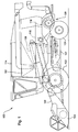
- FIGURE 1 illustrates an agricultural harvester 100 in accordance with the present invention.
- the harvester comprises a harvester vehicle 102 having a harvesting head 104 supported on a feederhouse 106 that is mounted on the front of harvester vehicle 102 on the vehicle chassis 107.
- a longitudinally extending rotor 108 is disposed to rotate within a concave 110 to separate crop material (i.e. grain) from crop residue.
- An oscillating cleaning shoe 112 is supported underneath the concave to receive crop material.
- the crop material is cleaned in the cleaning shoe and is carried upward into a grain tank 114.
- Crop residue leaving the rear end of rotor 108 is directed into a beater 116 which separates some residual crop material from the crop residue and directs that residual crop material into the cleaning shoe 112.
- Crop residue exiting the beater 116 is directed rearward into an inlet 118 of chopper 120.
- crop residue separated from the material in the cleaning shoe 112 is also directed into chopper 120.
- the crop residue exiting beater 116 typically includes cornstalks.
- the crop residue exiting the cleaning shoe typically includes chaff and other light crop residue.
- Identically arranged left and right front wheels 122 are coupled to the chassis 107 to support the front of the harvester on the ground. They are driven in rotation by hydraulic drive motors to propel the harvester.
- Identically arranged left and right rear drive wheels 124, 126 are coupled to the chassis 107 to support the rear of the harvester on the ground.
- the chassis 107 is supported on a rear axle assembly 128 that includes a steerable rear axle 130 supported on front and rear axle mounts 132, 134.
- Front and rear axle mounts 132, 134 are fixed to the bottom of the chassis 107 and support central axle member 136 for pivoting about longitudinal pivot axis 138.
- the central axle member 136 is in the form of a cross, with a forwardly extending tubular coupling 139 supported for pivoting in front axle mount 132 and a rearwardly extending tubular coupling 140 supported for pivoting in rear axle mount 134.
- Central axle member 136 also comprises right and left outer axle members 142, 144 that are fixed rigidly to, and extend to the right and to the left from, the couplings 139, 140 to form the rigid elongate central axle member on 36.
- the rear axle assembly 128 is symmetric about a vertical plane that passes longitudinally through the agricultural harvester and in particular through the longitudinal pivot axis 138. Henceforth, any discussion of one side of the rear axle assembly is true for the other side as well.
- Rear axle assembly 128 further includes right and left extendible axle members 146, 148 that are slidably supported in right and left outer axle members 142, 144, respectively, to be slid in and out by hydraulic actuators 150, 152 here shown as hydraulic cylinders (on the right side) and hydraulic actuators 154, 156, here shown as hydraulic cylinders (on the left side).
- the hydraulic actuators are disposed on each side of the outer axle members and are coupled at their inner ends to their respective outer axle member and at their outer ends to right and left and left steering knuckles 158, 160 that in turn are pivotally mounted to steering knuckle mounts on the outer ends of the extendible axle members.
- the extendible axle members can be extended from or retracted into the outer axle members by extending or retracting the hydraulic cylinders.
- the steering knuckles are pivotally coupled to the ends of the extendible axle members and can be steered to the left or right by extending one of the hydraulic actuators more or less than the other of the hydraulic actuators.
- the right and left steering knuckles 158, 160 support right and left hydraulic motors 162, 164 on lower and upper, right and left steering knuckle mounts 176, 178, 180, 182 that are coupled to and drive right and left planetary gearboxes 166, 168.
- Right and left output shafts from the planetary gearboxes drive right and left wheel hubs 170, 172, in rotation.
- Each of the wheel hubs has a flange 174 to which the rear wheels are attached.
- the hydraulic motors drive the wheels in rotation. Since they are mounted to the steering knuckles, the motors and the wheels can be extended or steered to the right and to the left by selectively extending and retracting the hydraulic actuators.
- the right outer axle member 142 is comprised of an elongate tubular structure 200 having a constant cross sectional profile over its length that supports the right extendible axle member 146 over substantially the entire length of the right extendible axle member when the right extendible axle member is inserted completely into the outer axle member.
- Inside planar top surfaces 202, 204 support V-shaped planar bearings 208, 210.
- Planar bottom surface 212 supports two elongate triangular adjustment members 214, 216, which in turn support V-shaped bearings 218, 220.
- Elongate tubular structure 200 has a peaked top surface 222. This peaked arrangement helps prevent plant matter from collecting on top of the axle. By keeping the top of elongate tubular structure 200 clean, less material falls long to the exposed upper surface of extendable axle member 146, and therefore less material contaminates the sliding bearing surfaces of V-shaped planar bearings 208, 210.
- Spaced apart rectangular slots 224, 226 are configured to receive guide members 228, 230 that are fixed to the top of V-shaped planar bearings 208, 210.
- Removable fasteners 232, 234 fix guide members 228, 230 to a central web 236, 238 of V-shaped planar bearings 208, 210 to extend upwardly therefrom.
- the outer and upper surfaces 240, 242 of V-shaped planar bearings 208, 210 abut the inside top surfaces 202, 204 of elongate tubular structure 200.
- Inside top surfaces 202,204 are disposed at a 90° angle to each other.
- Upper surfaces 240, 242 are disposed at a 90° angle to each other and are coplanar with inside top surfaces 202, 204, respectively.
- each of V-shaped planar bearings 208, 210 are planar and are disposed at a 90° angle to each other. They are also parallel to and spaced equidistantly from outer and upper surfaces 240, 242, respectively.
- Inner surfaces 248, 250 are configured to slidingly engage two upper and outer surfaces 252, 254 of right side extendable axle member 146. Upper and outer surfaces 252, 254 are also disposed at a 90° angle to each other.
- V-shaped bearings 208, 210 are held in place with respect to elongate tubular structure 200 by guide members 228, 230.
- right extendable axle member 146 is extended and retracted with respect to elongate tubular structure 200 by hydraulic cylinders 150, 152, surfaces 252, 254 function as bearings and slide against inner surfaces 248, 250.
- V-shaped bearings 208, 210 are disposed one behind the other longitudinally along the inside length of elongate tubular structure 200. In the preferred arrangement illustrated here, two V-shaped bearings 208, 210 are provided to support right extendable axle member 146 within elongate tubular structure 200. In an alternative arrangement, more V-shaped bearings could be provided to support the extendable axle member 146 over greater length when the extendable axle member 146 is completely retracted within elongate tubular member 200.
- the two elongate triangular adjustment members 214, 216 are disposed inside and rest upon the planar bottom surface 212 of elongate tubular structure 200. They are not fixed to the planar bottom surface 212, but can be translated in a direction perpendicular to the longitudinal extent of elongate tubular member 200, toward and away from the lower portion of extendable axle member 146.
- two first bolts 300 extend through a clearance aperture 302 in a first lower sidewall 304 of elongate tubular structure 200.
- Bolts 300 extend through a second clearance aperture 306 in elongate triangular adjustment member 214.
- Bolts 300 are then threadedly engaged in a threaded aperture 308 in the elongate triangular adjustment member 216.
- the threaded free end portions of bolts 300 extend completely through a third clearance aperture 310 in a second lower sidewall 312 of elongate tubular structure 200.
- Lock nuts 314 are threadedly engaged to the portion of bolts 300 that extends completely through elongate tubular structure 200, and are locked against the outer surface of second lower sidewall 312 to prevent bolts 300 from rotating with respect to elongate tubular structure 200.
- bolts 300 are under tension and hold elongate triangular adjustment member 216 against an outer lower surface of V-shaped bearings 218, 220.
- an outward force is applied by extendable axle member 146 to V-shaped bearings 218, 220, which is further communicated to elongate triangular adjustment members 214, 216, attempting to drive them apart (i.e. to drive member 214 to the left, and to drive member 216 to the right in Figure 5 ).
- the rightward force applied to elongate triangular adjustment member 216 is resisted by bolts 300, which are placed in tension by this rightward force. This rightward force is communicated through the threads of the adjustment member 216 into the threads of the bolts 300, and up the shaft of the bolts, where rightward movement is resisted by the heads 217 of bolts 300.
- Bolts 320 are identically arranged as bolts 300, and provide the identical function as bolts 300, by extending in the opposite direction as bolts 300 through a clearance hole in lower sidewall 312, through another clearance hole in elongate triangular adjustment member 216, and are threadedly engaged to elongate triangular adjustment member 214 in an identical fashion, but in a mirror image arrangement.
- Bolts 320 by their threaded engagement with elongate triangular adjustment member 214, resist outward forces against member 214, and communicate those tensile forces to the heads of bolts 320.
- Elongate triangular adjustment members 214, 216 are provided to eliminate slack between the extendable axle member 146 and elongate tubular structure 200. As the bearing surfaces 322, 324 provided on the V-shaped bearings 218, 220 begin to wear, slack is produced. This slack is eliminated by loosening the lock nuts on bolts 300, 320, then tightening bolts 300, 320. Tightening the bolts draws elongate triangular adjustment members 214, 216 inwardly toward each other in a horizontal direction across the planar bottom surface 212 of elongate tubular structure 200.
- Elongate triangular adjustment members 214, 216 have two bearing support surfaces 326, 328 that bear against bearing surfaces 330, 332. As bearing support surfaces 326, 328 are drawn together in this adjustment process, they slide inward against bearing surfaces 330, 332 from opposite sides and in opposite directions thereby forcing V-shaped bearings 218, 220 straight upward (assuming members 214, 216 are adjusted the same distance), eliminating the slack, and moving sliding bearing surfaces 322, 324 upward against the lower bearing surfaces 334, 336 of extendable axle member 146. When bolts 300, 320 are tightened an equal amount, the effect is to lift extendable axle member 146 straight upward, without bringing it closer to one side or the other of elongate tubular structure 200. It retains its fore-and-aft position in the axle assembly. This beneficially maintains the steerable rear axle dynamics and its caster and camber angles.
- V-shaped bearings 218, 220 therefore slide in the longitudinal direction (the front to rear direction) with respect to their supporting members (members 214, 216) while translating vertically with respect to the axle housing (structure 200).
- V-shaped bearings 218, 220 are pinched from both sides between members 214, 216 when the gap between members 214, 216 is narrowed and are thereby forced upward, reducing the slack.
- Surfaces 322, 324 are at a 90° angle with respect to each other and are each at 45° with respect to vertical.
- Surfaces 326, 328 are at a 90° angle with respect to each other, and are each at 45° with respect to vertical.
- Surfaces 330, 332 are at a 90° angle with respect to each other, and are each at 45° with respect to vertical.
- Surfaces 334, 336 are at a 90° angle with respect to each other, and are each at 45° with respect to vertical.
- Surfaces 322, 326, 330 and 334 are planar and parallel to each other.
- Surfaces 324, 328, 332, and 336 are planar and parallel to each other.
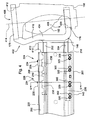
- the extendible axle member 146 is formed of an elongate portion 400 that is fixed to and formed integral with a C-frame 402, which is in turn comprised of a vertical member 404 to which an upper horizontal member 406 is fixed and to which a lower horizontal member 408 is fixed.
- Elongate telescopic portion 400 is formed integral with or is fixed permanently to C-frame 402.
- the former is preferably achieved by simultaneously casting or forging the C-frame 402 and the elongate telescopic portion 400.
- the latter is preferably achieved by welding C-frame 402 to elongate telescopic portion 400.
- Elongate telescopic portion 400 has bearing surfaces 252, 254, 334, 336, each disposed at a 45° angle with respect to vertical.
- Bearing surfaces 252, 254, 334, 336 form beveled corners of elongate telescopic portion 400.
- the surfaces are planar and extend substantially the entire length of elongate telescopic portion 400.
- Elongate telescopic portion 400 is configured to be received completely within elongate tubular structure 200 such that it is supported solely upon bearing surfaces 248, 250, 322, and 324 of V-shaped bearings 208, 210, 218, and 220.
- Bearing surfaces 248, 250, 322, and 324 are disposed at four corners of elongate tubular structure 200 and support the elongate telescopic portion 400 at four corners.
- the four bearing surfaces 248, 250, 322, and 324 support elongate telescopic portion 400 within elongate tubular structure 200 such that the bottom wall and sidewalls of elongate tubular structure 200 would do not contact elongate telescopic portion 400.
- the bottom wall, top wall, and sidewalls of elongate telescopic portion 400 do not contact elongate tubular structure 200.
- Vertical member 404 is larger in left side view (i.e. as viewed in Figure 6 : in a direction parallel to the longitudinal extent of elongate telescopic portion 400) than the elongate telescopic portion 400. Vertical member 400 cannot therefore be received in the open outer end 410 of tubular structure 200.
- elongate tubular structure 200 is constructed together with the V-shaped bearings 208, 210, 218, 220 permits a very compact telescopic portion -- compact in both the vertical and horizontal directions -- that permits the axle itself to be made light weight and smaller, such that the C-frame 402 extends forward of the forwardmost portion of elongate telescopic portion 400, the C-frame 402 extends behind the rearmost portion of elongate telescopic portion 400, the C-frame 402 extends above the uppermost portion of elongate telescopic portion 400, and the C-frame 402 extends below the lowermost portion of elongate telescopic portion 400.
- Upper horizontal member 406 has a steering knuckle mount 178.
- Lower horizontal member 408 has a steering knuckle mount 176.
- Steering knuckle mount 178 is defined by a first aperture 412 that defines a generally vertical steering axis 414.
- Steering knuckle mount 176 is defined by a second aperture 420 having a smaller diameter than the diameter of first aperture 412.
- Axis 414 passes through and is defined by the center of second aperture 420.
- Axis 414 is oriented generally vertically and preferably slightly away from vertical to provide a suitable caster angle and camber angle for the right rear wheel.
- vertical member 404 is provided with a bend 416 that permits an upper portion of vertical member 404 to extend over the top of outer end 410 of tubular structure 200.
- the position 418 of outer end 410 when elongate portion 400 is completely retracted into elongate tubular structure 200 is shown in dashed lines in Figure 4 .
- the elongate portion 400 is fixed asymmetrically to vertical member 404, such that the center of area 422 ( Fig. 6 ) of the elongate telescopic portion is disposed below the vertical midline 424 of the vertical member 404.
- elongate portion 400 is fixed to the bottom half of vertical member 404 completely below the vertical midline 424 of the vertical member 404.
- This arrangement provides a housing for the motor 162, the housing being defined by the C-frame 402 and steering knuckle 158 which substantially enclose hydraulic motor 162.
- the elongate telescopic portion 400 is rectangular, not square. It is greater in its vertical extent (height) than in its horizontal extent (width). This offsets diagonally disposed bearing surface 254, 334 and diagonally disposed bearing surface pair 252, 336.
- Each of the two diagonally offset pair of bearings 254, 334, and 252, 336 have surfaces that are opposed to each other: the surfaces lie in parallel planes, facing in opposite directions.
- the motor 162 drives the wheel on the end of extendable axle portion 146 in rotation
- one pair of diagonally opposed bearing surfaces 254, 334 resists motor-induced rotation in one direction
- the other pair of diagonally opposed bearing surfaces 252, 336 resists motor-induced rotation in the other direction.
- the forces applied to each bearing surface are normal to that bearing surface. They are distributed evenly across the entire bearing surface, and therefore can be modeled by a single force vector located at the midline of the bearing surface.
- the force vector due to motor torque applied to surface 254 is identified as "Va".
- the force vector due to motor torque applied to surface 252 is identified as “Vb”.
- the force vector due to motor torque applied to surface 334 is identified as “Vc”.
- the force vector due to motor torque applied to surface 336 is identified as “Vd”. (Fig. 7)
- the lines of action of the forces acting on diagonally opposed surfaces are offset from each other by a distance “Da” and “Db”.
- the offset distances "Da” and “Db” illustrated herein are equal since the elongate telescopic portion 400 is symmetrical.
- Each diagonally opposed pair of bearing surfaces shown in the illustrations herein is completely offset.
- a plane 426 disposed between bearing surface 254 and bearing surface 334 that extends perpendicular to the bearing surfaces and hence parallel to the forces acting on the bearing surfaces does not intersect either bearing surfaces.
- Plane 426 is illustrated herein passing through the center of area 422 of elongate telescopic portion 400, although it need not do so. Forces therefore cannot act on any portion of the bearing surface and be directly opposed along the same axis by a force applied to the diagonally opposed bearing surface. All the forces applied to diagonally opposing bearing surfaces generate a torque resisting the torque generated by motor 162.
- a force applied to any portion of the bearing surfaces 254, 334 generates a torque.
- the elongate telescopic portion 400 can resist torques applied when it accelerates in the forward direction and in the reverse direction.
- Vertical member 404 is fixed to and formed integral with the outer end of elongate telescopic portion 400 such that vertical member 402 of C-frame 402 is in an abutting relation with elongate telescopic portion 400.
- Elongate telescopic portion 400 is hollow over substantially its entire length, and is enclosed at its outer end by vertical member 404 which is fixed across this opening. This provides superior strength as compared to axles in which the C-frame is entirely eliminated and upper and lower steering knuckle mounts are formed in the top wall and bottom wall of an elongate extendable tubular portion similar to the elongate telescopic portion 400.
Landscapes
- Engineering & Computer Science (AREA)
- Mechanical Engineering (AREA)
- Life Sciences & Earth Sciences (AREA)
- Environmental Sciences (AREA)
- Chemical & Material Sciences (AREA)
- Combustion & Propulsion (AREA)
- Transportation (AREA)
- Vehicle Body Suspensions (AREA)
- Body Structure For Vehicles (AREA)
Claims (15)
- Ausziehbares Achsglied (146, 148) für eine landwirtschaftliche Erntemaschine (100), wobei die Erntemaschine ein Chassis (107) aufweist, das auf zwei angetriebenen Vorderrädern (122) und zwei angetriebenen und lenkbaren Hinterrädern (124) gestützt wird, wobei die Hinterräder (124) auf einer Hinterachsanordnung (128) gestützt werden, die ein zentrales Achsglied (136) aufweist, das so an dem Chassis gestützt wird, dass es um eine horizontale und sich in Längsrichtung erstreckende Achse schwenken kann, wobei das zentrale Achsglied (136) ein linkes und ein rechtes äußeres Achsglied (142, 144) aufweist, wobei das linke und das rechte äußere Achsglied (142, 144) jeweils dazu konfiguriert sind, das ausziehbare Achsglied (146, 148) teleskopisch aufzunehmen und zu stützen, wobei das ausziehbare Achsglied (146, 148) einen länglichen Teleskopabschnitt (400) mit einer allgemein rechteckigen Form und einer horizontalen oberen und unteren Wand sowie vertikalen Seitenwänden umfasst,
dadurch gekennzeichnet, dass die vier Seitenwände an vier abgeschrägten Ecken zusammentreffen, wobei jede der vier abgeschrägten Ecken eine Lagerfläche (252, 254, 334, 336) definiert und die vier Lagerflächen (252, 254, 334, 336) länglich, planar und in einem spitzen Winkel zu sowohl der Vertikalen als auch der Horizontalen angeordnet sind, und wobei ferner die vier Lagerflächen (252, 254, 334, 336) so angeordnet sind, dass sie im Wesentlichen die gesamte durch das ausziehbare Achsglied (146, 148) ausgeübte Last auf das äußere Achsglied (142, 144) übertragen. - Ausziehbares Achsglied (146, 148) nach Anspruch 1, wobei die vier Lagerflächen (252, 254, 334, 336) in einem rechtwinkligen oder trapezförmigen Muster angeordnet sind.
- Ausziehbares Achsglied (146, 148) nach Anspruch 1, wobei die beiden oberen Lagerflächen (252, 254) der vier Lagerflächen (252, 254, 334, 336) nach oben und nach außen vom ausziehbaren Achsglied (142, 144) weg weisen und die beiden unteren Lagerflächen (334, 336) der vier Lagerflächen (252, 254, 334, 336) nach unten und nach außen vom ausziehbaren Achsglied (142, 144) weg weisen.
- Ausziehbares Achsglied (146, 148) nach Anspruch 1, wobei die vier Lagerflächen (252, 254, 334, 336) in einem Winkel von 45 Grad bezüglich der Vertikalen und der Horizontalen angeordnet sind.
- Ausziehbares Achsglied (146, 148) nach Anspruch 4, wobei die vier Lagerflächen (252, 254, 334, 336) zwei obere Lagerflächen (252, 254) und zwei untere Lagerflächen (334, 336) umfassen, wobei eine erste obere Lagerfläche (252) direkt über einer ersten unteren Lagerfläche (334) angeordnet ist und eine zweite obere Lagerfläche (254) über einer zweiten unteren Lagerfläche (336) angeordnet ist.
- Ausziehbares Achsglied (146, 148) nach Anspruch 5, wobei jede der Lagerflächen (252, 254, 334, 336) eine Ebene definiert, die vertikal zur Lagerfläche ist und sich von ihr nach außen erstreckt, wobei die Ebene so angeordnet ist, dass der sich von jeder der Lagerflächen nach außen erstreckende Abschnitt nicht die Ebenen einer der anderen Lagerflächen schneidet.
- Ausziehbares Achsglied (146, 148) nach Anspruch 1, wobei ein äußeres Ende des ausziehbaren Achsglieds (142, 144) Achsschenkelhalter (178, 176) umfasst.
- Ausziehbares Achsglied (146, 148) nach Anspruch 7, wobei die Achsschenkelhalter (178, 176) eine Achsschenkeldrehachse (414) definieren und wobei ferner die Achse (414) zwischen vertikalen Paaren (252, 334 und 254, 336) der vier Lagerflächen (252, 254, 334, 336) angeordnet ist.
- Ausziehbares Achsglied (146, 148) nach Anspruch 8, wobei die Achsschenkeldrehachse (414) allgemein vertikal ist.
- Ausziehbares Achsglied (146, 148) nach Anspruch 1, wobei die vier Lagerflächen (252, 254, 334, 336) zwei Paare Lagerflächen (252, 336 und 254, 334) enthalten, wobei jedes Paar zwei an diagonal gegenüberliegenden Ecken des länglichen Teleskopabschnitts (400) angeordnete Lagerflächen enthält, wobei jede Lagerfläche jedes Paars parallel zur anderen Lagerfläche jedes Paars ist.
- Ausziehbares Achsglied (146, 148) nach Anspruch 1, wobei jede Lagerfläche (252, 254, 334, 336) so angeordnet ist, dass durch eine an jede Lagerfläche eines Paars diagonal gegenüberliegender Lagerflächen (252, 336 und 254, 334) senkrecht zu der Lagerfläche gleichmäßig angelegte Kraft ein Drehmoment an den länglichen Teleskopabschnitt (400) angelegt wird.
- Ausziehbares Achsglied (146, 148) nach Anspruch 1, wobei die vier Lagerflächen ein erstes Paar (252, 336) und ein zweites Paar (254, 334) Lagerflächen enthalten, wobei jede Lagerfläche des ersten Paars und des zweiten Paars diagonal gegenüberliegende Ecken des länglichen Teleskopabschnitts (400) definiert, und wobei ferner eine erste sich in Längsrichtung erstreckende Ebene, die durch eine Mitte von Bereich (422) des länglichen Teleskopabschnitts (400) verläuft und auch senkrecht zu mindestens einer der beiden Flächen (252, 336) des ersten Paars ist, so angeordnet ist, dass sich die beiden Flächen (252, 336) des ersten Paars auf gegenüberliegenden Seiten der ersten sich in Längsrichtung erstreckenden Ebene befinden.
- Ausziehbares Achsglied (146, 148) nach Anspruch 12, wobei beide Flächen (252, 336) des ersten Paars senkrecht zur ersten sich in Längsrichtung erstreckenden Ebene sind.
- Ausziehbares Achsglied (146, 148) nach Anspruch 12, wobei eine zweite sich in Längsrichtung erstreckende Ebene, die durch eine Mitte von Bereich (422) des länglichen Teleskopabschnitts verläuft und auch senkrecht zu mindestens einer der beiden Flächen (254, 334) des zweiten Paars ist, so angeordnet ist, dass sich die beiden Flächen (254, 334) des zweiten Paars auf gegenüberliegenden Seiten der zweiten sich in Längsrichtung erstreckenden Ebene befinden.
- Landwirtschaftliche Erntemaschine (100) mit einem Chassis (107), das auf zwei angetriebenen Vorderrädern (122) und zwei angetriebenen und lenkbaren Hinterrädern (124) gestützt wird, wobei die Hinterräder (124) auf einer Hinterachsanordnung (128) gestützt werden, die ein zentrales Achsglied (136) aufweist, das so an dem Chassis gestützt wird, dass es um eine horizontale und sich in Längsrichtung erstreckende Achse schwenken kann, wobei das zentrale Achsglied (136) ein linkes und ein rechtes äußeres Achsglied (142, 144) aufweist, wobei das linke und das rechte äußere Achsglied (142, 144) jeweils dazu konfiguriert sind, ein ausziehbares Achsglied (146, 148) nach einem der vorhergehenden Ansprüche teleskopisch aufzunehmen und zu stützen.
Applications Claiming Priority (1)
| Application Number | Priority Date | Filing Date | Title |
|---|---|---|---|
| US12/774,354 US8398179B2 (en) | 2010-05-05 | 2010-05-05 | Extendible axle member for the rear of an agricultural harvester |
Publications (2)
| Publication Number | Publication Date |
|---|---|
| EP2384909A1 EP2384909A1 (de) | 2011-11-09 |
| EP2384909B1 true EP2384909B1 (de) | 2013-04-03 |
Family
ID=44310890
Family Applications (1)
| Application Number | Title | Priority Date | Filing Date |
|---|---|---|---|
| EP11162226A Active EP2384909B1 (de) | 2010-05-05 | 2011-04-13 | Ein ausziehbares Achselement für das Heck einer landwirtschaftlichen Erntemaschine |
Country Status (4)
| Country | Link |
|---|---|
| US (1) | US8398179B2 (de) |
| EP (1) | EP2384909B1 (de) |
| AU (1) | AU2011202013A1 (de) |
| BR (1) | BRPI1102422A2 (de) |
Families Citing this family (14)
| Publication number | Priority date | Publication date | Assignee | Title |
|---|---|---|---|---|
| US20110042916A1 (en) * | 2009-02-11 | 2011-02-24 | Ananthakrishna Anil | Monocoque structure of an electrically powered motorized vehicle |
| US8573846B2 (en) * | 2010-05-05 | 2013-11-05 | Deere & Company | Bearing arrangement for a telescopic axle |
| MX355335B (es) | 2012-08-31 | 2018-04-13 | Monsanto Technology Llc | Sistema dinámico de sembradora con espacio entre hileras. |
| BE1021148B1 (nl) * | 2013-05-14 | 2016-01-08 | Cnh Industrial Belgium Nv | Landbouwmachine met wielen met verstelbare camber |
| US9346497B2 (en) * | 2014-04-09 | 2016-05-24 | Hagie Manufacturing Company | Variable tread width vehicle |
| US10556476B2 (en) | 2014-04-09 | 2020-02-11 | Hagie Manufacturing Company | Agricultural vehicle including ride height adjustable suspension |
| BE1022411B1 (nl) | 2014-12-18 | 2016-03-24 | Cnh Industrial Belgium Nv | As voor een oogstmachine |
| US9527536B1 (en) | 2015-08-24 | 2016-12-27 | Deere & Company | Telescopic wheel hub |
| US9718507B2 (en) * | 2015-10-29 | 2017-08-01 | Cnh Industrial America Llc | Method of steering a weight transfer axle on a combine |
| JP6754630B2 (ja) * | 2016-06-27 | 2020-09-16 | 株式会社クボタ | 車軸装置 |
| EP3651998A4 (de) | 2017-07-12 | 2021-03-31 | AxleTech International IP Holdings, LLC | Einstellbare achsanordnung für ein fahrzeug |
| US10710405B2 (en) | 2017-12-07 | 2020-07-14 | Cnh Industrial America Llc | Telescoping axle insert with contoured inner end for an agricultural product applicator |
| US10798863B2 (en) | 2017-12-27 | 2020-10-13 | Cnh Industrial America Llc | Input source and speed based control of track-width in a self-propelled agricultural product applicator |
| US11230152B1 (en) * | 2019-02-25 | 2022-01-25 | Demetrios C. Mavrofrides | Vehicle rear suspension and methods of operation |
Family Cites Families (14)
| Publication number | Priority date | Publication date | Assignee | Title |
|---|---|---|---|---|
| US2151045A (en) | 1935-10-22 | 1939-03-21 | French & Hecht Inc | Wheel mounting |
| US2750199A (en) * | 1953-07-08 | 1956-06-12 | Angus L Hart | Front wheel mounting for tractors |
| FR2249545A5 (de) * | 1973-10-25 | 1975-05-23 | Poclain Sa | |
| US4040643A (en) | 1975-10-15 | 1977-08-09 | Roberts Industries, Inc. | Adjustable vehicle axle |
| IT1236484B (it) | 1989-12-15 | 1993-03-09 | Carraro Spa | Assale sterzante a carreggiata variabile |
| US5326128A (en) * | 1991-09-09 | 1994-07-05 | Csn Manufacturing, Inc. | Variable-width torsion spring axle |
| US5489114A (en) * | 1994-09-29 | 1996-02-06 | Kidde Industries, Inc. | Tie rod extendable and retractable telescopic axle assembly |
| US5464243A (en) | 1995-01-13 | 1995-11-07 | Deere & Company | Adjustable axle with shim structure |
| US6386554B1 (en) * | 2000-02-02 | 2002-05-14 | Equipment Technologies, Inc. | Apparatus and method for operating a hydraulic suspension system of a crop sprayer |
| US6206125B1 (en) * | 2000-02-02 | 2001-03-27 | Equipment Technologies, Inc. | Apparatus and method for locking an adjustable width axle assembly of a crop sprayer |
| BR0100322A (pt) * | 2001-01-15 | 2002-09-17 | Jacto Maquinas Agricolas | Transmissão mec nica para veìculos agrìcolas de bitola variável |
| DE10247699B4 (de) * | 2002-10-12 | 2007-08-09 | Deere & Company, Moline | Lenkeinrichtung einer landwirtschaftlichen Erntemaschine |
| US7163227B1 (en) * | 2003-12-17 | 2007-01-16 | Burns Kerry C | Multi-position track width sensor for self-propelled agricultural sprayers |
| US8042817B2 (en) * | 2009-12-22 | 2011-10-25 | Agco Corporation | Adjustable height device for high clearance vehicle |
-
2010
- 2010-05-05 US US12/774,354 patent/US8398179B2/en active Active
-
2011
- 2011-04-13 EP EP11162226A patent/EP2384909B1/de active Active
- 2011-05-02 AU AU2011202013A patent/AU2011202013A1/en not_active Abandoned
- 2011-05-04 BR BRPI1102422-4A patent/BRPI1102422A2/pt not_active Application Discontinuation
Also Published As
| Publication number | Publication date |
|---|---|
| US20110273003A1 (en) | 2011-11-10 |
| US8398179B2 (en) | 2013-03-19 |
| BRPI1102422A2 (pt) | 2012-10-23 |
| AU2011202013A1 (en) | 2011-11-24 |
| EP2384909A1 (de) | 2011-11-09 |
Similar Documents
| Publication | Publication Date | Title |
|---|---|---|
| EP2384909B1 (de) | Ein ausziehbares Achselement für das Heck einer landwirtschaftlichen Erntemaschine | |
| US8205899B2 (en) | Extendible axle member for the rear of an agricultural harvester | |
| EP2384907B1 (de) | Lageranordnung für eine ausziehbare Achse | |
| US11420677B2 (en) | Mounting assembly for a steerable wheel with variable track width | |
| DE3851843T2 (de) | Aufhängesystem für kettenfahrzeuge. | |
| EP2192026B2 (de) | Landwirtschaftliche Zugmaschine | |
| US8454032B2 (en) | Self-propelled lawn mower and sulky device | |
| US6267198B1 (en) | Offset kingpin for a rear steering axle on an agricultural combine | |
| DE4340384B4 (de) | Heuwerbungsmaschine | |
| EP1894462B1 (de) | Landwirtschaftliches Trägerfahrzeug | |
| DE102019215146A1 (de) | Feldhäcksler mit einem tragenden Rahmengestell | |
| US4720233A (en) | Tractor frame for tractor-mounted implement | |
| AU2019322897B2 (en) | Assembly for converting a wheel drive harvester to track drive | |
| US20260053095A1 (en) | Header trailer system | |
| JPS59202938A (ja) | 農用トラクタ | |
| US20250256792A9 (en) | Assembly for Converting a Wheel Drive Harvester to Track Drive | |
| EP1782674B1 (de) | Mähmaschine | |
| DE2612876A1 (de) | Antriebseinheit mit zwei raedern | |
| BE1031829A1 (de) | Heckgewichtzusammenbau zur Anbringung an einem Feldhäcksler | |
| CA1263629A (en) | Tractor frame for tractor-mounted implement | |
| DE102005059698A1 (de) | Selbstfahrende landwirtschaftliche Erntemaschine mit Lenkeinrichtung | |
| DE102019215143A1 (de) | Feldhäcksler mit zweiteiligem Übergangsgehäuse |
Legal Events
| Date | Code | Title | Description |
|---|---|---|---|
| AK | Designated contracting states |
Kind code of ref document: A1 Designated state(s): AL AT BE BG CH CY CZ DE DK EE ES FI FR GB GR HR HU IE IS IT LI LT LU LV MC MK MT NL NO PL PT RO RS SE SI SK SM TR |
|
| AX | Request for extension of the european patent |
Extension state: BA ME |
|
| PUAI | Public reference made under article 153(3) epc to a published international application that has entered the european phase |
Free format text: ORIGINAL CODE: 0009012 |
|
| 17P | Request for examination filed |
Effective date: 20120509 |
|
| RIC1 | Information provided on ipc code assigned before grant |
Ipc: B62D 49/06 20060101ALI20121011BHEP Ipc: A01D 41/12 20060101ALI20121011BHEP Ipc: B60B 35/10 20060101AFI20121011BHEP |
|
| GRAP | Despatch of communication of intention to grant a patent |
Free format text: ORIGINAL CODE: EPIDOSNIGR1 |
|
| GRAS | Grant fee paid |
Free format text: ORIGINAL CODE: EPIDOSNIGR3 |
|
| GRAA | (expected) grant |
Free format text: ORIGINAL CODE: 0009210 |
|
| AK | Designated contracting states |
Kind code of ref document: B1 Designated state(s): AL AT BE BG CH CY CZ DE DK EE ES FI FR GB GR HR HU IE IS IT LI LT LU LV MC MK MT NL NO PL PT RO RS SE SI SK SM TR |
|
| REG | Reference to a national code |
Ref country code: GB Ref legal event code: FG4D |
|
| REG | Reference to a national code |
Ref country code: AT Ref legal event code: REF Ref document number: 604462 Country of ref document: AT Kind code of ref document: T Effective date: 20130415 Ref country code: CH Ref legal event code: EP |
|
| REG | Reference to a national code |
Ref country code: IE Ref legal event code: FG4D |
|
| REG | Reference to a national code |
Ref country code: DE Ref legal event code: R096 Ref document number: 602011001277 Country of ref document: DE Effective date: 20130529 |
|
| REG | Reference to a national code |
Ref country code: AT Ref legal event code: MK05 Ref document number: 604462 Country of ref document: AT Kind code of ref document: T Effective date: 20130403 |
|
| PG25 | Lapsed in a contracting state [announced via postgrant information from national office to epo] |
Ref country code: SI Free format text: LAPSE BECAUSE OF FAILURE TO SUBMIT A TRANSLATION OF THE DESCRIPTION OR TO PAY THE FEE WITHIN THE PRESCRIBED TIME-LIMIT Effective date: 20130403 |
|
| REG | Reference to a national code |
Ref country code: NL Ref legal event code: VDEP Effective date: 20130403 |
|
| REG | Reference to a national code |
Ref country code: LT Ref legal event code: MG4D |
|
| PG25 | Lapsed in a contracting state [announced via postgrant information from national office to epo] |
Ref country code: AT Free format text: LAPSE BECAUSE OF FAILURE TO SUBMIT A TRANSLATION OF THE DESCRIPTION OR TO PAY THE FEE WITHIN THE PRESCRIBED TIME-LIMIT Effective date: 20130403 Ref country code: IS Free format text: LAPSE BECAUSE OF FAILURE TO SUBMIT A TRANSLATION OF THE DESCRIPTION OR TO PAY THE FEE WITHIN THE PRESCRIBED TIME-LIMIT Effective date: 20130803 Ref country code: LT Free format text: LAPSE BECAUSE OF FAILURE TO SUBMIT A TRANSLATION OF THE DESCRIPTION OR TO PAY THE FEE WITHIN THE PRESCRIBED TIME-LIMIT Effective date: 20130403 Ref country code: PT Free format text: LAPSE BECAUSE OF FAILURE TO SUBMIT A TRANSLATION OF THE DESCRIPTION OR TO PAY THE FEE WITHIN THE PRESCRIBED TIME-LIMIT Effective date: 20130805 Ref country code: SE Free format text: LAPSE BECAUSE OF FAILURE TO SUBMIT A TRANSLATION OF THE DESCRIPTION OR TO PAY THE FEE WITHIN THE PRESCRIBED TIME-LIMIT Effective date: 20130403 Ref country code: GR Free format text: LAPSE BECAUSE OF FAILURE TO SUBMIT A TRANSLATION OF THE DESCRIPTION OR TO PAY THE FEE WITHIN THE PRESCRIBED TIME-LIMIT Effective date: 20130704 Ref country code: NL Free format text: LAPSE BECAUSE OF FAILURE TO SUBMIT A TRANSLATION OF THE DESCRIPTION OR TO PAY THE FEE WITHIN THE PRESCRIBED TIME-LIMIT Effective date: 20130403 Ref country code: ES Free format text: LAPSE BECAUSE OF FAILURE TO SUBMIT A TRANSLATION OF THE DESCRIPTION OR TO PAY THE FEE WITHIN THE PRESCRIBED TIME-LIMIT Effective date: 20130714 Ref country code: NO Free format text: LAPSE BECAUSE OF FAILURE TO SUBMIT A TRANSLATION OF THE DESCRIPTION OR TO PAY THE FEE WITHIN THE PRESCRIBED TIME-LIMIT Effective date: 20130703 Ref country code: FI Free format text: LAPSE BECAUSE OF FAILURE TO SUBMIT A TRANSLATION OF THE DESCRIPTION OR TO PAY THE FEE WITHIN THE PRESCRIBED TIME-LIMIT Effective date: 20130403 |
|
| PG25 | Lapsed in a contracting state [announced via postgrant information from national office to epo] |
Ref country code: BG Free format text: LAPSE BECAUSE OF FAILURE TO SUBMIT A TRANSLATION OF THE DESCRIPTION OR TO PAY THE FEE WITHIN THE PRESCRIBED TIME-LIMIT Effective date: 20130703 Ref country code: CY Free format text: LAPSE BECAUSE OF FAILURE TO SUBMIT A TRANSLATION OF THE DESCRIPTION OR TO PAY THE FEE WITHIN THE PRESCRIBED TIME-LIMIT Effective date: 20130403 Ref country code: HR Free format text: LAPSE BECAUSE OF FAILURE TO SUBMIT A TRANSLATION OF THE DESCRIPTION OR TO PAY THE FEE WITHIN THE PRESCRIBED TIME-LIMIT Effective date: 20130403 Ref country code: LV Free format text: LAPSE BECAUSE OF FAILURE TO SUBMIT A TRANSLATION OF THE DESCRIPTION OR TO PAY THE FEE WITHIN THE PRESCRIBED TIME-LIMIT Effective date: 20130403 Ref country code: PL Free format text: LAPSE BECAUSE OF FAILURE TO SUBMIT A TRANSLATION OF THE DESCRIPTION OR TO PAY THE FEE WITHIN THE PRESCRIBED TIME-LIMIT Effective date: 20130403 Ref country code: RS Free format text: LAPSE BECAUSE OF FAILURE TO SUBMIT A TRANSLATION OF THE DESCRIPTION OR TO PAY THE FEE WITHIN THE PRESCRIBED TIME-LIMIT Effective date: 20130403 |
|
| REG | Reference to a national code |
Ref country code: IE Ref legal event code: MM4A |
|
| PG25 | Lapsed in a contracting state [announced via postgrant information from national office to epo] |
Ref country code: EE Free format text: LAPSE BECAUSE OF FAILURE TO SUBMIT A TRANSLATION OF THE DESCRIPTION OR TO PAY THE FEE WITHIN THE PRESCRIBED TIME-LIMIT Effective date: 20130403 Ref country code: DK Free format text: LAPSE BECAUSE OF FAILURE TO SUBMIT A TRANSLATION OF THE DESCRIPTION OR TO PAY THE FEE WITHIN THE PRESCRIBED TIME-LIMIT Effective date: 20130403 Ref country code: SK Free format text: LAPSE BECAUSE OF FAILURE TO SUBMIT A TRANSLATION OF THE DESCRIPTION OR TO PAY THE FEE WITHIN THE PRESCRIBED TIME-LIMIT Effective date: 20130403 Ref country code: MC Free format text: LAPSE BECAUSE OF FAILURE TO SUBMIT A TRANSLATION OF THE DESCRIPTION OR TO PAY THE FEE WITHIN THE PRESCRIBED TIME-LIMIT Effective date: 20130403 Ref country code: CZ Free format text: LAPSE BECAUSE OF FAILURE TO SUBMIT A TRANSLATION OF THE DESCRIPTION OR TO PAY THE FEE WITHIN THE PRESCRIBED TIME-LIMIT Effective date: 20130403 |
|
| PLBE | No opposition filed within time limit |
Free format text: ORIGINAL CODE: 0009261 |
|
| STAA | Information on the status of an ep patent application or granted ep patent |
Free format text: STATUS: NO OPPOSITION FILED WITHIN TIME LIMIT |
|
| PG25 | Lapsed in a contracting state [announced via postgrant information from national office to epo] |
Ref country code: RO Free format text: LAPSE BECAUSE OF FAILURE TO SUBMIT A TRANSLATION OF THE DESCRIPTION OR TO PAY THE FEE WITHIN THE PRESCRIBED TIME-LIMIT Effective date: 20130403 |
|
| 26N | No opposition filed |
Effective date: 20140106 |
|
| REG | Reference to a national code |
Ref country code: FR Ref legal event code: ST Effective date: 20140303 |
|
| REG | Reference to a national code |
Ref country code: DE Ref legal event code: R097 Ref document number: 602011001277 Country of ref document: DE Effective date: 20140106 |
|
| PG25 | Lapsed in a contracting state [announced via postgrant information from national office to epo] |
Ref country code: IE Free format text: LAPSE BECAUSE OF NON-PAYMENT OF DUE FEES Effective date: 20130413 |
|
| PG25 | Lapsed in a contracting state [announced via postgrant information from national office to epo] |
Ref country code: FR Free format text: LAPSE BECAUSE OF NON-PAYMENT OF DUE FEES Effective date: 20130603 |
|
| PGFP | Annual fee paid to national office [announced via postgrant information from national office to epo] |
Ref country code: IT Payment date: 20140430 Year of fee payment: 4 |
|
| REG | Reference to a national code |
Ref country code: CH Ref legal event code: PL |
|
| PG25 | Lapsed in a contracting state [announced via postgrant information from national office to epo] |
Ref country code: LI Free format text: LAPSE BECAUSE OF NON-PAYMENT OF DUE FEES Effective date: 20140430 Ref country code: CH Free format text: LAPSE BECAUSE OF NON-PAYMENT OF DUE FEES Effective date: 20140430 |
|
| PG25 | Lapsed in a contracting state [announced via postgrant information from national office to epo] |
Ref country code: MT Free format text: LAPSE BECAUSE OF FAILURE TO SUBMIT A TRANSLATION OF THE DESCRIPTION OR TO PAY THE FEE WITHIN THE PRESCRIBED TIME-LIMIT Effective date: 20130403 |
|
| PG25 | Lapsed in a contracting state [announced via postgrant information from national office to epo] |
Ref country code: SM Free format text: LAPSE BECAUSE OF FAILURE TO SUBMIT A TRANSLATION OF THE DESCRIPTION OR TO PAY THE FEE WITHIN THE PRESCRIBED TIME-LIMIT Effective date: 20130403 |
|
| PG25 | Lapsed in a contracting state [announced via postgrant information from national office to epo] |
Ref country code: TR Free format text: LAPSE BECAUSE OF FAILURE TO SUBMIT A TRANSLATION OF THE DESCRIPTION OR TO PAY THE FEE WITHIN THE PRESCRIBED TIME-LIMIT Effective date: 20130403 |
|
| PG25 | Lapsed in a contracting state [announced via postgrant information from national office to epo] |
Ref country code: MK Free format text: LAPSE BECAUSE OF FAILURE TO SUBMIT A TRANSLATION OF THE DESCRIPTION OR TO PAY THE FEE WITHIN THE PRESCRIBED TIME-LIMIT Effective date: 20130403 Ref country code: LU Free format text: LAPSE BECAUSE OF NON-PAYMENT OF DUE FEES Effective date: 20130413 Ref country code: HU Free format text: LAPSE BECAUSE OF FAILURE TO SUBMIT A TRANSLATION OF THE DESCRIPTION OR TO PAY THE FEE WITHIN THE PRESCRIBED TIME-LIMIT; INVALID AB INITIO Effective date: 20110413 |
|
| GBPC | Gb: european patent ceased through non-payment of renewal fee |
Effective date: 20150413 |
|
| PG25 | Lapsed in a contracting state [announced via postgrant information from national office to epo] |
Ref country code: IT Free format text: LAPSE BECAUSE OF NON-PAYMENT OF DUE FEES Effective date: 20150413 Ref country code: GB Free format text: LAPSE BECAUSE OF NON-PAYMENT OF DUE FEES Effective date: 20150413 |
|
| PG25 | Lapsed in a contracting state [announced via postgrant information from national office to epo] |
Ref country code: AL Free format text: LAPSE BECAUSE OF FAILURE TO SUBMIT A TRANSLATION OF THE DESCRIPTION OR TO PAY THE FEE WITHIN THE PRESCRIBED TIME-LIMIT Effective date: 20130403 |
|
| PGFP | Annual fee paid to national office [announced via postgrant information from national office to epo] |
Ref country code: BE Payment date: 20240429 Year of fee payment: 14 |
|
| PGFP | Annual fee paid to national office [announced via postgrant information from national office to epo] |
Ref country code: DE Payment date: 20250319 Year of fee payment: 15 |
|
| REG | Reference to a national code |
Ref country code: BE Ref legal event code: MM Effective date: 20250430 |
|
| PG25 | Lapsed in a contracting state [announced via postgrant information from national office to epo] |
Ref country code: BE Free format text: LAPSE BECAUSE OF NON-PAYMENT OF DUE FEES Effective date: 20250430 |