EP2383775B1 - Method for obtaining a layer of AlN with substantially vertical flanks - Google Patents
Method for obtaining a layer of AlN with substantially vertical flanks Download PDFInfo
- Publication number
- EP2383775B1 EP2383775B1 EP11163944.9A EP11163944A EP2383775B1 EP 2383775 B1 EP2383775 B1 EP 2383775B1 EP 11163944 A EP11163944 A EP 11163944A EP 2383775 B1 EP2383775 B1 EP 2383775B1
- Authority
- EP
- European Patent Office
- Prior art keywords
- layer
- substrate
- aln
- mask
- etching
- Prior art date
- Legal status (The legal status is an assumption and is not a legal conclusion. Google has not performed a legal analysis and makes no representation as to the accuracy of the status listed.)
- Active
Links
Images


Classifications
-
- H—ELECTRICITY
- H10—SEMICONDUCTOR DEVICES; ELECTRIC SOLID-STATE DEVICES NOT OTHERWISE PROVIDED FOR
- H10P—GENERIC PROCESSES OR APPARATUS FOR THE MANUFACTURE OR TREATMENT OF DEVICES COVERED BY CLASS H10
- H10P50/00—Etching of wafers, substrates or parts of devices
- H10P50/20—Dry etching; Plasma etching; Reactive-ion etching
- H10P50/28—Dry etching; Plasma etching; Reactive-ion etching of insulating materials
- H10P50/282—Dry etching; Plasma etching; Reactive-ion etching of insulating materials of inorganic materials
- H10P50/283—Dry etching; Plasma etching; Reactive-ion etching of insulating materials of inorganic materials by chemical means
- H10P50/285—Dry etching; Plasma etching; Reactive-ion etching of insulating materials of inorganic materials by chemical means of materials not containing Si, e.g. PZT or Al2O3
-
- H—ELECTRICITY
- H10—SEMICONDUCTOR DEVICES; ELECTRIC SOLID-STATE DEVICES NOT OTHERWISE PROVIDED FOR
- H10N—ELECTRIC SOLID-STATE DEVICES NOT OTHERWISE PROVIDED FOR
- H10N30/00—Piezoelectric or electrostrictive devices
- H10N30/01—Manufacture or treatment
- H10N30/07—Forming of piezoelectric or electrostrictive parts or bodies on an electrical element or another base
- H10N30/074—Forming of piezoelectric or electrostrictive parts or bodies on an electrical element or another base by depositing piezoelectric or electrostrictive layers, e.g. aerosol or screen printing
- H10N30/076—Forming of piezoelectric or electrostrictive parts or bodies on an electrical element or another base by depositing piezoelectric or electrostrictive layers, e.g. aerosol or screen printing by vapour phase deposition
-
- H—ELECTRICITY
- H10—SEMICONDUCTOR DEVICES; ELECTRIC SOLID-STATE DEVICES NOT OTHERWISE PROVIDED FOR
- H10P—GENERIC PROCESSES OR APPARATUS FOR THE MANUFACTURE OR TREATMENT OF DEVICES COVERED BY CLASS H10
- H10P50/00—Etching of wafers, substrates or parts of devices
- H10P50/20—Dry etching; Plasma etching; Reactive-ion etching
- H10P50/28—Dry etching; Plasma etching; Reactive-ion etching of insulating materials
- H10P50/282—Dry etching; Plasma etching; Reactive-ion etching of insulating materials of inorganic materials
-
- H—ELECTRICITY
- H10—SEMICONDUCTOR DEVICES; ELECTRIC SOLID-STATE DEVICES NOT OTHERWISE PROVIDED FOR
- H10N—ELECTRIC SOLID-STATE DEVICES NOT OTHERWISE PROVIDED FOR
- H10N30/00—Piezoelectric or electrostrictive devices
- H10N30/01—Manufacture or treatment
- H10N30/08—Shaping or machining of piezoelectric or electrostrictive bodies
- H10N30/082—Shaping or machining of piezoelectric or electrostrictive bodies by etching, e.g. lithography
Definitions
- the invention relates to techniques for etching a material such as AlN, with a view to producing a layer of this material with one or more straight flanks, that is to say substantially perpendicular to a surface on which this layer is deposited or formed.
- substantially perpendicular means that the flank makes with said surface an angle greater than or equal to 75 °.
- This type of material is used in the production of MEMS components, for example of the type requiring a piezoelectric or dielectric layer with straight flanks.
- Such a resonator comprises a piezoelectric layer which must have one or vertical flanks, in order to prevent the propagation of parasitic waves.
- this type of material is also used in the realization of capacitive detection MEMS, which require fine and vertical "gap", or in the production of gyroscopes.
- Dry or wet etching techniques all have an isotropic character. They result in one or flanks not having the character of verticality desired: the material is indeed etched in a vertical direction, but also in a horizontal direction.
- the invention firstly relates to a method of producing an AlN layer with at least one substantially vertical or perpendicular flank with respect to a surface of a substrate, according to claim 1.
- the walk pattern defines a raised portion of the pattern relative to a lower level.
- Deposition of the AlN layer is performed on the raised portion and on the lower level.
- substantially perpendicular vertical means that the flank makes with said surface an angle greater than or equal to 75 °.
- Such a method may comprise a preliminary step of forming the topology of the substrate, by etching the surface of the substrate, so as to obtain at least the step type pattern.
- the step may have at least one lateral flank forming an angle at most equal to 15 ° relative to the perpendicular to the surface of the substrate in or on which it is made.
- the substrate comprises an underlayer, a surface of which forms, with the surface of the substrate, the walk-type pattern.
- This underlayer can be obtained by depositing a uniform layer of material, then etching at least this layer, to obtain the walk-type pattern.
- At least a portion of the underlayer and / or at least a portion of the mask layer may form an electrode.
- a method according to the invention may further comprise producing an inclined flank by etching the AlN layer.
- the etching of the AlN layer is of wet etching type.
- a method according to the invention may also make it possible to produce at least one hole with vertical edges, the diameter of the hole and the thickness of the AlN layer preferably having a diameter / thickness ratio of less than 0.5.
- the topology can result from an etching of the surface of the substrate so as to obtain at least the step type pattern.
- the step may have at least one lateral flank forming an angle at most equal to 15 ° relative to the perpendicular to the surface of the substrate in or on which it is made.
- the substrate may comprise an underlayer, a surface of which forms, with the surface of the substrate, the walk-type pattern.
- the sub-layer may be formed at least in part on a layer forming a surface topology of the support substrate.
- a layer 4 which can be continuous or connected but which is not necessarily: in the example of the Figure 1A this layer comprises a first part 4 which is separated from a second part 4 'by an opening 6 which reveals the surface 2' of the substrate 2.
- This opening is for example obtained by etching a continuous initial layer of the material of the parts 4,4 ', etching which stops on the surface 2' of the substrate 2.
- the references 12 and 14 designate the flanks respectively of the portions 4 ' and 4 of this layer, on both sides of the opening 6. Two other flanks are designated by the references 10 and 12, to the left and to the right of the Figure 1A .
- this layer 4, 4 ', as well as the topology 4a, 4'a, 4b formed in the embodiments of the Figures 5A-5D and 6A-6D is lined or surrounded by a surface 2 'of the substrate located at a lower level than the upper level or the raised portion of the layer 4, 4' or topology 4a, 4'a, 4b.
- flanks 10, 12, 14, 16 are straight, that is to say substantially perpendicular to the surface 2 'of the substrate 2 or form with the perpendicular to this surface an angle less than or equal to 15 °.
- the material of the layer 4, 4 ' is, for example, titanium (Ti) or silicon (Si), or molybdenum (Mo), or platinum (Pt), or silicon nitride (SiN or Si 3 N 4 ) or silicon oxide (SiO 2 ).
- This layer 4, 4 ' may have a thickness of the order of 200 nm, or, more generally, between 10 nm and 1 ⁇ m or between 100 nm and 300 nm.
- a layer 7 of texturing or germination which will help to orient the material 31 which will then be deposited, may have been previously formed on the surface of the substrate 2.
- a layer 31 of AlN for example of approximately thickness equal to 1 micron or, more generally, between 10 nm and 5 microns.
- a deposition technique that can be used is the PVD (Physical Vapor Deposition) technique.
- This layer 31 is uniformly deposited on the portions 4, 4 'of the previously obtained layer (also known as the underlayer or topology layer), as well as on the parts of the surface 2' of the substrate 2 which are exposed, or again at the same time on the lower level defined by the layer 4, 4 'on the surface 2' and on the upper level or on the raised part of the layer 4, 4 '(or of the topology 4a, 4'a, 4b in others Figures 5A - 6D ).
- the portions 4, 4 'of the previously obtained layer also known as the underlayer or topology layer
- edges 20, 22, 24 define with, respectively, each of the edges 10, 12, 14 of the layer 4, 4 'a plane which is substantially perpendicular to the surface 2' of the substrate 2.
- this plane may not be strictly perpendicular to the surface 2 ', but be slightly inclined relative to the perpendicular direction, for example an angle between 0 ° and 15 °.
- This mask layer 40, 40 ' has a thickness which may be for example between 10 nm and 10 ⁇ m. It can be by example molybdenum Mo or silicon nitride (SiN, Si 3 N 4 ).
- the alignment of the edges 20, 22, 24 with, respectively, each of the edges 10, 12, 14 can be obtained with an accuracy of the order of 1 ⁇ m or less than 1 ⁇ m, for example an accuracy of ⁇ 1 ⁇ m on a stepper 1X, ⁇ 150 nm for deep UV lithographs (called “deep uv”) and ⁇ 50 nm for "ebeam” type lithographs.
- This alignment will make it possible to define a high end 30 1 , 32 1 , 34 1 and a low end 30 2 , 32 2 , 34 2 of the flanks 30, 32, 34 which will be made in the layer 31.
- edges of the mask 40, 40 ' will define the upper ends 30 1 , 32 1 , 34 1 of the sidewalls to be engraved (in other words, these high ends are positioned where the edges of the mask are positioned).
- edges of the layer 4, 4 ' will define the lower ends 2 , 32 2 , 34 2 of the flanks to be etched (in other words, these low ends are positioned where the edges of this layer are positioned).
- one of the flanks of the mask 40 here the right flank 26, is not aligned with the right flank 16 of the underlayer 4.
- An etching step is then performed, as shown in FIG. figure 1D .
- This step will make it possible to etch the layer 31 of AlN material, in areas that are not protected by the mask 40, 40 '.
- This etching is continued to the surface 2 'of substrate 2, this surface 2 'reappears therefore after the etching is complete.
- each flank which extends between a high end 30 1 , 32 1 , 34 1 and a low end 30 2 , 32 2 , 34 2 and is defined by the corresponding pair of high and low end 30 1 , 32 1 , 34 1 and 30 2 , 32 2 , 34 2 .
- the etching leads to the formation of a hole 60 between two portions 31a, 31b of AIN which are located under the portions 40, 40 'of hard mask.
- this hole is the flanks 32, 34 which, as indicated above, are perpendicular to the surface 2 'of the layer 2.
- the right flank 26 of the mask layer 40 is not aligned with the right flank 16 of the growth layer 4.
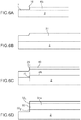
- a layer 3 is first formed, of thickness e, with a view to creating a topology in the future underlayer 4 (or, where again, topology layer).
- This layer 3 may for example be a layer for defining an electrode. It is for example SiO 2 or SiN or molybdenum (Mo) or platinum (Pt). Its thickness e is for example between 10 nm and 1 micron, or between 100 nm and 300 nm.
- a layer 4 is then deposited, the nature and thickness of which may be those already mentioned for the first embodiment.
- a layer 4 is obtained, part of which rests directly on the surface 2 'of the substrate 2, and of which another part rests on the surface 3' of the layer 3.
- the edges 13a, 13b of the layer 3 are reflected in the deposited layer 4 by flanks 10a, 10b which can be slightly inclined relative to a direction perpendicular to the surface 2 '.
- This aspect is represented in more detail in figure 3 , where it can be seen that the flank 10a defines, with a horizontal plane (reference is taken here as the surface 3 'of the layer 3), an angle ⁇ which can be of the order of 80 ° or more.
- the layer 4 has generated a step in the layer 4, of height substantially equal to the thickness e of the layer 3.
- the edges of this step are not necessarily strictly perpendicular to the surface 2 'of the substrate 2.
- the step is defined by both the lower level defined by the upper surface of the layer 4, in the areas where there is no underlying pattern 3, and the upper level or the raised portion of the same layer 4.
- a mask layer 40 is formed again, whose flanks 20, 22 are aligned - in the sense and in the manner already explained above - with the flanks 13a, 13b of the layer 3 and the flanks 10a, 10b of layer 4. This alignment will make it possible to define a high end 30 1 , 32 1 and a low end 30 2 , 32 2 of the flanks 30, 32 which will be made in the layer 31.
- edges of the mask 40 will define the upper ends 30 1 , 32 1 of the flanks to be engraved (in other words, these high ends are positioned where the edges of the mask are positioned).
- edges of the raised portion of the layer 4 will define the lower ends 2 , 32 2 of the flanks to be engraved (that is, these low ends are positioned where the edges of the raised portion of this layer are positioned) .
- This mask layer may form one or more electrodes.
- each flank which extends between a high end 30 1 , 32 1 and a low end 30 2 , 32 2 is defined by the corresponding pair of high and low end 30 1 , 32 1 and 2 , 32 2 .
- the thicknesses and materials for the layers 4, 31, 40 may be identical or similar to the thicknesses and materials indicated above, in the context of the first embodiment.
- the layer 3 it may be for example silicon dioxide (SiO 2 ), or silicon nitride (SiN), or molybdenum (Mo), or platinum (Pt) and have a thickness that can be understood as the underlayer 4, between 10 nm and 1 ⁇ m.
- the underlayer 4 is not necessarily engraved, but a topology, or step, or relief is created on the surface of this underlayer 4 by the formation, previously, of a layer underlying 3 presenting flanks which will result, during the deposition of the underlayer 4, also by flanks 10a, 10b.
- the etching of the layer 31 is then carried out in the areas not situated under the layer 40 of the mask. As before, the layer 31 is etched over its entire thickness, but the surface 4 'of the underlayer 4 is then updated.
- a portion 31a is thus obtained in AlN, with side flanks 30, 32, which are again found to be perpendicular to the horizontal surface defined here by the upper surface 4 'of the underlayer 4.
- the layer 3 it is possible to use the layer 3 to form a topology or a relief in the underlayer 4 whose edges 10a, 10b, in turn, allow to align the edges of the mask layer 40 and to define the areas in which vertical sides of the layer 31 will be obtained, after etching.
- this second embodiment it is also possible to make one or more holes such as the hole 60 of the figure 1D , with vertical flanks and with the geometric characteristics already mentioned above.
- one or more several inclined flanks, such as the flank 36 of the figure 1D are examples of the flanks, such as the flank 36 of the figure 1D .
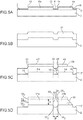
- a topology is produced, thus a surface exhibiting variations in altitude.
- Parts 4a, 4'a are thus raised (higher level) relative to the rest of the surface 2 ', which forms the lower level.
- These portions have edges 10, 12, 14 substantially perpendicular to this surface 2 '.
- the raised portion can be continuous or connected.
- These portions 4a, 4'a can be obtained by etching a substrate 2 initially uniformly plan, they can therefore be of the same material as the substrate 2.
- This layer 31 is uniformly deposited on the raised portions 4a, 4a 'of the substrate, as well as on the other parts of the surface 2' of the substrate 2 which are at a lower level.
- This alignment will make it possible to define a high end 30 1 , 32 1 , 34 1 and a low end 30 2 , 32 2 , 34 2 of the flanks 30, 32, 34 which will be made in the layer 31.
- edges of the mask 40, 40 ' will define the upper ends 30 1 , 32 1 , 34 1 of the sidewalls to be engraved (in other words, these high ends are positioned where the edges of the mask are positioned).
- edges of the raised portions 4a, 4 'a will define the low ends 2 , 32 2 , 34 2 of the flanks to be engraved (in other words, these low ends are positioned where the edges of these raised portions are positioned) .
- flanks 30, 32, 34 of the AlN layer 31 are perpendicular to the surface 2 'of the substrate 2, or their inclination with respect to this perpendicular is less than a few degrees, for example less than ⁇ 15 °.
- etching leads to the formation of a hole 60, between two portions 31a, 31b of AlN which are located under the portions 40, 40 'of hard mask.
- the right flank 26 of the mask layer 40 is not aligned with the right flank 16 of the growth layer 4.
- a topology is produced with a surface that has a step 10, the latter delimiting a portion 4b raised relative to the rest of the surface 2 '.
- This configuration can result from the etching of an initially uniformly plane substrate.
- the topology or the relief can be obtained by engraving of this same layer (case of Figures 1A-1D ), or by growth of this layer on a pre-existing topology (case of Figures 2A and 2B ), or by etching the substrate 2 (case of Figures 5A - 6D ).
- the technique presented above makes it possible to obtain straight flanks in a layer of AlN, without overgrafting.
Landscapes
- Engineering & Computer Science (AREA)
- Manufacturing & Machinery (AREA)
- Micromachines (AREA)
- Cold Cathode And The Manufacture (AREA)
- Weting (AREA)
- Led Devices (AREA)
- Piezo-Electric Or Mechanical Vibrators, Or Delay Or Filter Circuits (AREA)
- Chemical Vapour Deposition (AREA)
- Ceramic Products (AREA)
- Crystals, And After-Treatments Of Crystals (AREA)
Claims (10)
- Verfahren zur Herstellung einer AlN-Schicht mit Flanken, die im Wesentlichen vertikal bezüglich einer Oberfläche (4', 2') eines Substrats (2) sind, wobei sich jede Flanke zwischen einem unteren Ende und einem oberen Ende erstreckt, wobei die Oberfläche des Substrats eine Topologie (4, 4', 4a, 4'a, 4b) aufweist, die wenigstens ein stufenförmiges Motiv (10, 12, 14, 16) umfasst, wobei dieses Verfahren umfasst:- Aufbringen der AlN-Schicht (31) wenigstens auf das Motiv der Topologie, wobei das obere Ende der Stufe dem unteren Ende der Flanke entspricht,- Bilden, von oberhalb der AlN-Schicht, einer Maskenschicht (40, 40'), von der wenigstens ein Rand derart positioniert ist, dass das obere Ende der Flanke definiert wird,- Ätzen der AlN-Schicht (31) durch die Maske hindurch, wobei das Ätzen der AlN-Schicht vom Typ Nassätzen ist, um die Flanke zu erhalten, wobei die Steilheit der Flanke durch die Position des oberen und des unteren Endes, deren Neigung einen Winkel von höchstens gleich 15° bezüglich der Normalen zur Oberfläche (4', 2') des Substrats (2) bildet.
- Verfahren nach Anspruch 1, umfassend einen vorherigen Schritt des Bildens der Topologie (4a, 4'a, 4b) des Substrats durch Ätzen der Oberfläche (4', 2') des Substrats (2) derart, dass wenigstens das stufenförmige Motiv erhalten wird.
- Verfahren nach einem der Ansprüche 1 oder 2, wobei die Stufe wenigstens eine laterale Flanke (10, 12, 14, 16) aufweist, die einen Winkel von höchstens gleich 15° bezüglich der Normalen zur Oberfläche (4', 2') des Substrats (2) bildet, in oder auf der sie realisiert ist.
- Verfahren nach einem der Ansprüche 1 bis 3, bei dem das Substrat eine Teilschicht (4, 4') umfasst, von der eine Oberfläche zusammen mit der Oberfläche des Substrats das stufenförmige Motiv bildet.
- Verfahren nach Anspruch 4, wobei die Teilschicht (4, 4') erhalten wird:- durch Aufbringen einer gleichförmigen Materialschicht und anschließendes Ätzen wenigstens dieser Schicht, um das stufenförmige Motiv zu erhalten;- oder durch Aufbringen auf einer Schicht (3), die eine Topologie an der Oberfläche (2') des Substrats (2) bildet.
- Verfahren nach einem der Ansprüche 4 oder 5, wobei wenigstens ein Teil der Teilschicht (4, 4') eine Elektrode bildet.
- Verfahren nach einem der vorhergehenden Ansprüche, wobei wenigstens ein Teil der Maskenschicht (40, 40') eine Elektrode bildet.
- Verfahren nach einem der vorhergehenden Ansprüche, wobei die Maskenschicht (40, 40') aus Siliziumdioxid (SiO2), oder aus Molybdän (Mo), oder aus Platin (Pt) oder aus einem haftenden Harz ist.
- Verfahren nach einem der vorhergehenden Ansprüche, ferner umfassend die Realisierung einer geneigten Flanke (36) durch Ätzen der AlN-Schicht (39).
- Verfahren nach einem der vorhergehenden Ansprüche, ferner umfassend die Realisierung eines Lochs (60) mit vertikalen Rändern.
Applications Claiming Priority (1)
| Application Number | Priority Date | Filing Date | Title |
|---|---|---|---|
| FR1053360A FR2959597B1 (fr) | 2010-04-30 | 2010-04-30 | Procede pour obtenir une couche d'aln a flancs sensiblement verticaux |
Publications (3)
| Publication Number | Publication Date |
|---|---|
| EP2383775A2 EP2383775A2 (de) | 2011-11-02 |
| EP2383775A3 EP2383775A3 (de) | 2012-11-07 |
| EP2383775B1 true EP2383775B1 (de) | 2017-03-15 |
Family
ID=43503564
Family Applications (1)
| Application Number | Title | Priority Date | Filing Date |
|---|---|---|---|
| EP11163944.9A Active EP2383775B1 (de) | 2010-04-30 | 2011-04-27 | Method for obtaining a layer of AlN with substantially vertical flanks |
Country Status (4)
| Country | Link |
|---|---|
| US (1) | US8460987B2 (de) |
| EP (1) | EP2383775B1 (de) |
| JP (2) | JP2011236121A (de) |
| FR (1) | FR2959597B1 (de) |
Families Citing this family (4)
| Publication number | Priority date | Publication date | Assignee | Title |
|---|---|---|---|---|
| CN112470260B (zh) * | 2018-05-23 | 2024-05-14 | 胜高股份有限公司 | Iii族氮化物半导体基板及其制造方法 |
| US10662058B1 (en) | 2019-03-05 | 2020-05-26 | Rosemount Aerospace Inc. | Wet etch patterning of an aluminum nitride film |
| CN110931495B (zh) * | 2019-12-11 | 2021-03-19 | 长江存储科技有限责任公司 | 一种三维存储器的制作方法 |
| EP3865954B1 (de) * | 2020-02-12 | 2025-08-13 | Nivarox-FAR S.A. | Herstellungsverfahren einer monoblock-vorrichtung mit federzungen aus silizium, für uhrwerk |
Citations (1)
| Publication number | Priority date | Publication date | Assignee | Title |
|---|---|---|---|---|
| US6306313B1 (en) * | 2000-02-04 | 2001-10-23 | Agere Systems Guardian Corp. | Selective etching of thin films |
Family Cites Families (11)
| Publication number | Priority date | Publication date | Assignee | Title |
|---|---|---|---|---|
| JP3649634B2 (ja) * | 1999-02-09 | 2005-05-18 | 東芝テック株式会社 | インクジェットプリンタヘッド及びその製造方法 |
| JP2002240271A (ja) * | 2001-02-20 | 2002-08-28 | Ricoh Co Ltd | インクジェット記録ヘッド |
| JP4290151B2 (ja) * | 2004-08-31 | 2009-07-01 | キヤノン株式会社 | 圧電/電歪体素子構造体及び圧電/電歪体素子構造体の製造方法、並びに液体噴射ヘッドの製造方法 |
| US8082640B2 (en) * | 2004-08-31 | 2011-12-27 | Canon Kabushiki Kaisha | Method for manufacturing a ferroelectric member element structure |
| US7492241B2 (en) * | 2005-06-02 | 2009-02-17 | The Regents Of The University Of California | Contour-mode piezoelectric micromechanical resonators |
| US7319284B2 (en) * | 2005-09-02 | 2008-01-15 | Precision Instrument Development Center National Applied Research Laboratories | Surface acoustic wave device and method for fabricating the same |
| US20070139140A1 (en) * | 2005-12-20 | 2007-06-21 | Rao Valluri R | Frequency tuning of film bulk acoustic resonators (FBAR) |
| WO2007119643A1 (ja) * | 2006-03-31 | 2007-10-25 | Ube Industries, Ltd. | 圧電薄膜共振子、圧電薄膜デバイスおよびその製造方法 |
| JP4361102B2 (ja) * | 2007-09-12 | 2009-11-11 | 富士フイルム株式会社 | 圧電素子の製造方法 |
| JP2009124640A (ja) * | 2007-11-19 | 2009-06-04 | Hitachi Media Electoronics Co Ltd | 薄膜圧電バルク波共振器およびその製造方法、並びに薄膜圧電バルク波共振器を用いた薄膜圧電バルク波共振器フィルタ |
| KR101606780B1 (ko) * | 2008-06-30 | 2016-03-28 | 더 리젠츠 오브 더 유니버시티 오브 미시건 | 압전 mems 마이크로폰 |
-
2010
- 2010-04-30 FR FR1053360A patent/FR2959597B1/fr active Active
-
2011
- 2011-04-27 EP EP11163944.9A patent/EP2383775B1/de active Active
- 2011-04-28 JP JP2011101247A patent/JP2011236121A/ja active Pending
- 2011-04-29 US US13/097,686 patent/US8460987B2/en active Active
-
2016
- 2016-06-22 JP JP2016123234A patent/JP6207680B2/ja active Active
Patent Citations (1)
| Publication number | Priority date | Publication date | Assignee | Title |
|---|---|---|---|---|
| US6306313B1 (en) * | 2000-02-04 | 2001-10-23 | Agere Systems Guardian Corp. | Selective etching of thin films |
Also Published As
| Publication number | Publication date |
|---|---|
| EP2383775A2 (de) | 2011-11-02 |
| JP6207680B2 (ja) | 2017-10-04 |
| US8460987B2 (en) | 2013-06-11 |
| EP2383775A3 (de) | 2012-11-07 |
| US20110266594A1 (en) | 2011-11-03 |
| FR2959597B1 (fr) | 2012-10-12 |
| FR2959597A1 (fr) | 2011-11-04 |
| JP2011236121A (ja) | 2011-11-24 |
| JP2016171351A (ja) | 2016-09-23 |
Similar Documents
| Publication | Publication Date | Title |
|---|---|---|
| EP2316784B1 (de) | Hohlraumverbindungsstruktur, die einen oder mehrere aufsteigende Leiter an den Wänden des Hohlraums aufweist, und entsprechendes Herstellungsverfahren | |
| EP2960203B1 (de) | Vorrichtung mit einer membran auf der basis von unter zugbelastung stehendem germanium | |
| EP2383775B1 (de) | Method for obtaining a layer of AlN with substantially vertical flanks | |
| EP1972002A1 (de) | Vereinfachtes verfahren zum herstellen einer epitaxial gewachsenen struktur | |
| EP2769249A1 (de) | Verfahren zur herstellung einer refraktiven oder diffraktiven optischen vorrichtung | |
| EP1458095B1 (de) | Verfahren zur Herstellung eines abstimmbaren piezoelektrischen Mikroresonators | |
| EP1156499A1 (de) | Mikroelektronisches Bauteil vom Typ variabler Kondensator oder Mikroschalter | |
| EP1890958B1 (de) | Mikromechanische komponente mit aktiven elementen und verfahren zur herstellung einer komponente dieser art | |
| CH701266A2 (fr) | Pièce de micromécanique composite et son procédé de fabrication. | |
| FR2948495A1 (fr) | Composants a contact électrique traversant et procédé de fabrication ainsi que système comportant de tels composants | |
| EP3925930B1 (de) | Verfahren zur herstellung einer mikroelektronischen vorrichtung mit einer membran, die über einen hohlraum gespannt ist | |
| CH701988B1 (fr) | Procédé de fabrication d'un évidement oblique dans une couche de silicium. | |
| WO2017009564A1 (fr) | Pochoir et procédé de fabrication du pochoir | |
| EP3412625A1 (de) | Herstellungsverfahren eines mikromechanischen bauteils | |
| EP4730049A1 (de) | Verfahren zur herstellung von uhrenkomponenten aus silizium | |
| FR3046291A1 (fr) | Circuit electronique comprenant des tranchees d'isolation electrique | |
| EP2884532B1 (de) | Herstellungsverfahren eines elektrisch leitenden Organs für elektronisches Bauteil, das an einem Ende mit einem Hohlraum ausgestattet ist | |
| EP4505512A1 (de) | Substrat mit vias und zugehörige herstellungsverfahren | |
| FR3143841A1 (fr) | Procédé de préparation d’un empilement en vue d’un collage | |
| EP3939935A1 (de) | Nanometrisches elektromechanisches stellglied und sein herstellungsverfahren | |
| WO2002076881A1 (fr) | Procede de fabrication d'une structure a membrane micro-usinee | |
| EP0338636A1 (de) | Verfahren zum Herstellen von elektrischen Kontakten von kleiner Dimension auf einer Halbleiterschaltung | |
| CH713854A2 (fr) | Procédé de fabrication d'une pièce micromécanique. |
Legal Events
| Date | Code | Title | Description |
|---|---|---|---|
| AK | Designated contracting states |
Kind code of ref document: A2 Designated state(s): AL AT BE BG CH CY CZ DE DK EE ES FI FR GB GR HR HU IE IS IT LI LT LU LV MC MK MT NL NO PL PT RO RS SE SI SK SM TR |
|
| AX | Request for extension of the european patent |
Extension state: BA ME |
|
| PUAI | Public reference made under article 153(3) epc to a published international application that has entered the european phase |
Free format text: ORIGINAL CODE: 0009012 |
|
| PUAL | Search report despatched |
Free format text: ORIGINAL CODE: 0009013 |
|
| AK | Designated contracting states |
Kind code of ref document: A3 Designated state(s): AL AT BE BG CH CY CZ DE DK EE ES FI FR GB GR HR HU IE IS IT LI LT LU LV MC MK MT NL NO PL PT RO RS SE SI SK SM TR |
|
| AX | Request for extension of the european patent |
Extension state: BA ME |
|
| RIC1 | Information provided on ipc code assigned before grant |
Ipc: H01L 41/22 20060101ALI20120928BHEP Ipc: H01L 21/311 20060101AFI20120928BHEP |
|
| 17P | Request for examination filed |
Effective date: 20130503 |
|
| 17Q | First examination report despatched |
Effective date: 20141013 |
|
| GRAP | Despatch of communication of intention to grant a patent |
Free format text: ORIGINAL CODE: EPIDOSNIGR1 |
|
| INTG | Intention to grant announced |
Effective date: 20160803 |
|
| GRAS | Grant fee paid |
Free format text: ORIGINAL CODE: EPIDOSNIGR3 |
|
| STAA | Information on the status of an ep patent application or granted ep patent |
Free format text: STATUS: GRANT OF PATENT IS INTENDED |
|
| GRAJ | Information related to disapproval of communication of intention to grant by the applicant or resumption of examination proceedings by the epo deleted |
Free format text: ORIGINAL CODE: EPIDOSDIGR1 |
|
| GRAL | Information related to payment of fee for publishing/printing deleted |
Free format text: ORIGINAL CODE: EPIDOSDIGR3 |
|
| STAA | Information on the status of an ep patent application or granted ep patent |
Free format text: STATUS: EXAMINATION IS IN PROGRESS |
|
| INTC | Intention to grant announced (deleted) | ||
| GRAR | Information related to intention to grant a patent recorded |
Free format text: ORIGINAL CODE: EPIDOSNIGR71 |
|
| STAA | Information on the status of an ep patent application or granted ep patent |
Free format text: STATUS: GRANT OF PATENT IS INTENDED |
|
| GRAA | (expected) grant |
Free format text: ORIGINAL CODE: 0009210 |
|
| STAA | Information on the status of an ep patent application or granted ep patent |
Free format text: STATUS: THE PATENT HAS BEEN GRANTED |
|
| AK | Designated contracting states |
Kind code of ref document: B1 Designated state(s): AL AT BE BG CH CY CZ DE DK EE ES FI FR GB GR HR HU IE IS IT LI LT LU LV MC MK MT NL NO PL PT RO RS SE SI SK SM TR |
|
| INTG | Intention to grant announced |
Effective date: 20170206 |
|
| REG | Reference to a national code |
Ref country code: CH Ref legal event code: EP Ref country code: GB Ref legal event code: FG4D Free format text: NOT ENGLISH |
|
| REG | Reference to a national code |
Ref country code: IE Ref legal event code: FG4D Free format text: LANGUAGE OF EP DOCUMENT: FRENCH |
|
| REG | Reference to a national code |
Ref country code: AT Ref legal event code: REF Ref document number: 876351 Country of ref document: AT Kind code of ref document: T Effective date: 20170415 |
|
| REG | Reference to a national code |
Ref country code: DE Ref legal event code: R096 Ref document number: 602011035877 Country of ref document: DE |
|
| REG | Reference to a national code |
Ref country code: FR Ref legal event code: PLFP Year of fee payment: 7 |
|
| REG | Reference to a national code |
Ref country code: NL Ref legal event code: MP Effective date: 20170315 |
|
| REG | Reference to a national code |
Ref country code: LT Ref legal event code: MG4D |
|
| PG25 | Lapsed in a contracting state [announced via postgrant information from national office to epo] |
Ref country code: FI Free format text: LAPSE BECAUSE OF FAILURE TO SUBMIT A TRANSLATION OF THE DESCRIPTION OR TO PAY THE FEE WITHIN THE PRESCRIBED TIME-LIMIT Effective date: 20170315 Ref country code: NO Free format text: LAPSE BECAUSE OF FAILURE TO SUBMIT A TRANSLATION OF THE DESCRIPTION OR TO PAY THE FEE WITHIN THE PRESCRIBED TIME-LIMIT Effective date: 20170615 Ref country code: GR Free format text: LAPSE BECAUSE OF FAILURE TO SUBMIT A TRANSLATION OF THE DESCRIPTION OR TO PAY THE FEE WITHIN THE PRESCRIBED TIME-LIMIT Effective date: 20170616 Ref country code: LT Free format text: LAPSE BECAUSE OF FAILURE TO SUBMIT A TRANSLATION OF THE DESCRIPTION OR TO PAY THE FEE WITHIN THE PRESCRIBED TIME-LIMIT Effective date: 20170315 Ref country code: HR Free format text: LAPSE BECAUSE OF FAILURE TO SUBMIT A TRANSLATION OF THE DESCRIPTION OR TO PAY THE FEE WITHIN THE PRESCRIBED TIME-LIMIT Effective date: 20170315 |
|
| REG | Reference to a national code |
Ref country code: AT Ref legal event code: MK05 Ref document number: 876351 Country of ref document: AT Kind code of ref document: T Effective date: 20170315 |
|
| PG25 | Lapsed in a contracting state [announced via postgrant information from national office to epo] |
Ref country code: RS Free format text: LAPSE BECAUSE OF FAILURE TO SUBMIT A TRANSLATION OF THE DESCRIPTION OR TO PAY THE FEE WITHIN THE PRESCRIBED TIME-LIMIT Effective date: 20170315 Ref country code: SE Free format text: LAPSE BECAUSE OF FAILURE TO SUBMIT A TRANSLATION OF THE DESCRIPTION OR TO PAY THE FEE WITHIN THE PRESCRIBED TIME-LIMIT Effective date: 20170315 Ref country code: LV Free format text: LAPSE BECAUSE OF FAILURE TO SUBMIT A TRANSLATION OF THE DESCRIPTION OR TO PAY THE FEE WITHIN THE PRESCRIBED TIME-LIMIT Effective date: 20170315 Ref country code: BG Free format text: LAPSE BECAUSE OF FAILURE TO SUBMIT A TRANSLATION OF THE DESCRIPTION OR TO PAY THE FEE WITHIN THE PRESCRIBED TIME-LIMIT Effective date: 20170615 |
|
| PG25 | Lapsed in a contracting state [announced via postgrant information from national office to epo] |
Ref country code: NL Free format text: LAPSE BECAUSE OF FAILURE TO SUBMIT A TRANSLATION OF THE DESCRIPTION OR TO PAY THE FEE WITHIN THE PRESCRIBED TIME-LIMIT Effective date: 20170315 |
|
| PG25 | Lapsed in a contracting state [announced via postgrant information from national office to epo] |
Ref country code: IT Free format text: LAPSE BECAUSE OF FAILURE TO SUBMIT A TRANSLATION OF THE DESCRIPTION OR TO PAY THE FEE WITHIN THE PRESCRIBED TIME-LIMIT Effective date: 20170315 Ref country code: ES Free format text: LAPSE BECAUSE OF FAILURE TO SUBMIT A TRANSLATION OF THE DESCRIPTION OR TO PAY THE FEE WITHIN THE PRESCRIBED TIME-LIMIT Effective date: 20170315 Ref country code: CZ Free format text: LAPSE BECAUSE OF FAILURE TO SUBMIT A TRANSLATION OF THE DESCRIPTION OR TO PAY THE FEE WITHIN THE PRESCRIBED TIME-LIMIT Effective date: 20170315 Ref country code: EE Free format text: LAPSE BECAUSE OF FAILURE TO SUBMIT A TRANSLATION OF THE DESCRIPTION OR TO PAY THE FEE WITHIN THE PRESCRIBED TIME-LIMIT Effective date: 20170315 Ref country code: RO Free format text: LAPSE BECAUSE OF FAILURE TO SUBMIT A TRANSLATION OF THE DESCRIPTION OR TO PAY THE FEE WITHIN THE PRESCRIBED TIME-LIMIT Effective date: 20170315 Ref country code: AT Free format text: LAPSE BECAUSE OF FAILURE TO SUBMIT A TRANSLATION OF THE DESCRIPTION OR TO PAY THE FEE WITHIN THE PRESCRIBED TIME-LIMIT Effective date: 20170315 Ref country code: SK Free format text: LAPSE BECAUSE OF FAILURE TO SUBMIT A TRANSLATION OF THE DESCRIPTION OR TO PAY THE FEE WITHIN THE PRESCRIBED TIME-LIMIT Effective date: 20170315 |
|
| PG25 | Lapsed in a contracting state [announced via postgrant information from national office to epo] |
Ref country code: SM Free format text: LAPSE BECAUSE OF FAILURE TO SUBMIT A TRANSLATION OF THE DESCRIPTION OR TO PAY THE FEE WITHIN THE PRESCRIBED TIME-LIMIT Effective date: 20170315 Ref country code: IS Free format text: LAPSE BECAUSE OF FAILURE TO SUBMIT A TRANSLATION OF THE DESCRIPTION OR TO PAY THE FEE WITHIN THE PRESCRIBED TIME-LIMIT Effective date: 20170715 Ref country code: PT Free format text: LAPSE BECAUSE OF FAILURE TO SUBMIT A TRANSLATION OF THE DESCRIPTION OR TO PAY THE FEE WITHIN THE PRESCRIBED TIME-LIMIT Effective date: 20170717 Ref country code: PL Free format text: LAPSE BECAUSE OF FAILURE TO SUBMIT A TRANSLATION OF THE DESCRIPTION OR TO PAY THE FEE WITHIN THE PRESCRIBED TIME-LIMIT Effective date: 20170315 |
|
| REG | Reference to a national code |
Ref country code: CH Ref legal event code: PL |
|
| REG | Reference to a national code |
Ref country code: DE Ref legal event code: R097 Ref document number: 602011035877 Country of ref document: DE |
|
| PLBE | No opposition filed within time limit |
Free format text: ORIGINAL CODE: 0009261 |
|
| STAA | Information on the status of an ep patent application or granted ep patent |
Free format text: STATUS: NO OPPOSITION FILED WITHIN TIME LIMIT |
|
| REG | Reference to a national code |
Ref country code: IE Ref legal event code: MM4A |
|
| PG25 | Lapsed in a contracting state [announced via postgrant information from national office to epo] |
Ref country code: MC Free format text: LAPSE BECAUSE OF FAILURE TO SUBMIT A TRANSLATION OF THE DESCRIPTION OR TO PAY THE FEE WITHIN THE PRESCRIBED TIME-LIMIT Effective date: 20170315 Ref country code: DK Free format text: LAPSE BECAUSE OF FAILURE TO SUBMIT A TRANSLATION OF THE DESCRIPTION OR TO PAY THE FEE WITHIN THE PRESCRIBED TIME-LIMIT Effective date: 20170315 |
|
| 26N | No opposition filed |
Effective date: 20171218 |
|
| PG25 | Lapsed in a contracting state [announced via postgrant information from national office to epo] |
Ref country code: SI Free format text: LAPSE BECAUSE OF FAILURE TO SUBMIT A TRANSLATION OF THE DESCRIPTION OR TO PAY THE FEE WITHIN THE PRESCRIBED TIME-LIMIT Effective date: 20170315 Ref country code: LI Free format text: LAPSE BECAUSE OF NON-PAYMENT OF DUE FEES Effective date: 20170430 Ref country code: CH Free format text: LAPSE BECAUSE OF NON-PAYMENT OF DUE FEES Effective date: 20170430 Ref country code: LU Free format text: LAPSE BECAUSE OF NON-PAYMENT OF DUE FEES Effective date: 20170427 |
|
| REG | Reference to a national code |
Ref country code: BE Ref legal event code: MM Effective date: 20170430 |
|
| REG | Reference to a national code |
Ref country code: FR Ref legal event code: PLFP Year of fee payment: 8 |
|
| PG25 | Lapsed in a contracting state [announced via postgrant information from national office to epo] |
Ref country code: IE Free format text: LAPSE BECAUSE OF NON-PAYMENT OF DUE FEES Effective date: 20170427 |
|
| PG25 | Lapsed in a contracting state [announced via postgrant information from national office to epo] |
Ref country code: BE Free format text: LAPSE BECAUSE OF NON-PAYMENT OF DUE FEES Effective date: 20170430 |
|
| PG25 | Lapsed in a contracting state [announced via postgrant information from national office to epo] |
Ref country code: MT Free format text: LAPSE BECAUSE OF FAILURE TO SUBMIT A TRANSLATION OF THE DESCRIPTION OR TO PAY THE FEE WITHIN THE PRESCRIBED TIME-LIMIT Effective date: 20170315 |
|
| PG25 | Lapsed in a contracting state [announced via postgrant information from national office to epo] |
Ref country code: HU Free format text: LAPSE BECAUSE OF FAILURE TO SUBMIT A TRANSLATION OF THE DESCRIPTION OR TO PAY THE FEE WITHIN THE PRESCRIBED TIME-LIMIT; INVALID AB INITIO Effective date: 20110427 |
|
| PG25 | Lapsed in a contracting state [announced via postgrant information from national office to epo] |
Ref country code: CY Free format text: LAPSE BECAUSE OF NON-PAYMENT OF DUE FEES Effective date: 20170315 |
|
| PG25 | Lapsed in a contracting state [announced via postgrant information from national office to epo] |
Ref country code: MK Free format text: LAPSE BECAUSE OF FAILURE TO SUBMIT A TRANSLATION OF THE DESCRIPTION OR TO PAY THE FEE WITHIN THE PRESCRIBED TIME-LIMIT Effective date: 20170315 |
|
| PG25 | Lapsed in a contracting state [announced via postgrant information from national office to epo] |
Ref country code: TR Free format text: LAPSE BECAUSE OF FAILURE TO SUBMIT A TRANSLATION OF THE DESCRIPTION OR TO PAY THE FEE WITHIN THE PRESCRIBED TIME-LIMIT Effective date: 20170315 |
|
| PG25 | Lapsed in a contracting state [announced via postgrant information from national office to epo] |
Ref country code: AL Free format text: LAPSE BECAUSE OF FAILURE TO SUBMIT A TRANSLATION OF THE DESCRIPTION OR TO PAY THE FEE WITHIN THE PRESCRIBED TIME-LIMIT Effective date: 20170315 |
|
| P01 | Opt-out of the competence of the unified patent court (upc) registered |
Effective date: 20230830 |
|
| PGFP | Annual fee paid to national office [announced via postgrant information from national office to epo] |
Ref country code: DE Payment date: 20250417 Year of fee payment: 15 |
|
| PGFP | Annual fee paid to national office [announced via postgrant information from national office to epo] |
Ref country code: GB Payment date: 20250424 Year of fee payment: 15 |
|
| PGFP | Annual fee paid to national office [announced via postgrant information from national office to epo] |
Ref country code: FR Payment date: 20250428 Year of fee payment: 15 |